WA-TX-03-R / WA-RX-03-R Operation Guide - Circuit Design, Inc.
WA-TX-03-R / WA-RX-03-R Operation Guide - Circuit Design, Inc.
WA-TX-03-R / WA-RX-03-R Operation Guide - Circuit Design, Inc.
- No tags were found...

You also want an ePaper? Increase the reach of your titles
YUMPU automatically turns print PDFs into web optimized ePapers that Google loves.
OPERATION GUIDE<br />
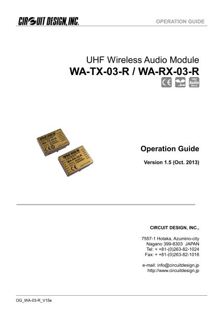
UHF Wireless Audio Module<br />
<strong>WA</strong>-<strong>TX</strong>-<strong>03</strong>-R / <strong>WA</strong>-<strong>RX</strong>-<strong>03</strong>-R<br />
<strong>Operation</strong> <strong>Guide</strong><br />
Version 1.5 (Oct. 2013)<br />
CIRCUIT DESIGN, INC.,<br />
7557-1 Hotaka, Azumino-city<br />
Nagano 399-83<strong>03</strong> JAPAN<br />
Tel: + +81-(0)263-82-1024<br />
Fax: + +81-(0)263-82-1016<br />
e-mail: info@circuitdesign.jp<br />
http://www.circuitdesign.jp<br />
OG_<strong>WA</strong>-<strong>03</strong>-R_V15e
OPERATION GUIDE<br />
CONTENTS<br />
GENERAL DESCRIPTION ................................................................3<br />
FEATURES .......................................................................................3<br />
APPLICATION ...................................................................................3<br />
SPECIFICATION ...............................................................................4<br />
TERMINAL DESCRIPTION ...............................................................5<br />
CHANNEL TABLE .............................................................................7<br />
REMARKS FOR INTEGRATION OF THE RECEIVER ANTENNA ....7<br />
CONNECTION DIAGRAM .................................................................8<br />
BLOCK DIAGRAM ............................................................................9<br />
DIMENSIONS ................................................................................. 11<br />
REGULATORY COMPLIANCE INFORMATION ..............................13<br />
DECLARATION OF CONFORMITY ................................................15<br />
CAUTIONS AND <strong>WA</strong>RNINGS..........................................................16<br />
REVISION HISTORY .......................................................................17<br />
OG_<strong>WA</strong>-<strong>03</strong>-R_V15e <strong>Circuit</strong> <strong>Design</strong>, <strong>Inc</strong>. 2
OPERATION GUIDE<br />
GENERAL DESCRIPTION<br />
The <strong>WA</strong>-<strong>TX</strong>-<strong>03</strong>-R / <strong>WA</strong>-<strong>RX</strong>-<strong>03</strong>-R are 15ch multichannel audio modules that operate<br />
in the European harmonized 863 - 865 MHz band. In addition to offering a frequency<br />
range sufficient for voice transmission, the compander noise reduction system has a<br />
wide dynamic range, enabling transmission of clear audio signals.<br />
As embedded devices, they include nearly all the parts necessary for audio<br />
transmission in a small shielding case, making it possible to develop audio<br />
transmission equipment in a short time.<br />
FEATURES<br />
‣ 863 – 865 MHz European Audio band<br />
‣ 15 channels, 125 kHz steps<br />
‣ 70 dB dynamic range with built in noise reduction system<br />
‣ 50 Hz - 13 kHz audio response<br />
‣ Low power operation<br />
‣ Adjustable mute level<br />
‣ Small size for embedding in user equipment<br />
‣ R&TTE (EN301 357) and RoHS compliant<br />
APPLICATIONS<br />
‣ Audio guiding in museums<br />
‣ Tour guide systems<br />
‣ Wireless conference systems<br />
‣ Wireless microphone systems for amateur users<br />
‣ Various audio transmissions<br />
‣ Voice monitoring<br />
OG_<strong>WA</strong>-<strong>03</strong>-R_V15e <strong>Circuit</strong> <strong>Design</strong>, <strong>Inc</strong>. 3
OPERATION GUIDE<br />
SPECIFICATION<br />
Common<br />
Items Specification Remarks<br />
Compatible standard EN 301 357 R&TTE<br />
Frequency range<br />
863 – 865 MHz<br />
Number of channels 15 125 kHz step<br />
Emission class<br />
F3E<br />
Operating distance 50 m Line-of-sight<br />
S/N ratio 70 dB or more W/IHF-A Filter<br />
Audio frequency response 50 Hz-13 kHz +/-3.5 dB<br />
T.H.D 2 % @AF 1kHz, Δf = 20kHz<br />
Emphasis<br />
50 us<br />
Operating temperature range 0 to 50 °C<br />
<strong>WA</strong>-<strong>TX</strong>-<strong>03</strong>-R (Transmitter)<br />
Items Specification Remarks<br />
Oscillation type<br />
Crystal based PLL oscillation<br />
RF power<br />
2 mW (e.r.p)<br />
Frequency stability<br />
+/- 15 kHz<br />
Noise reduction<br />
Compander<br />
Spurious emission<br />
1 uW max.<br />
Deviation 20 kHz 1 kHz @ -25 dBv<br />
AF input level - 93 to -13 dBv 1 kHz<br />
AF input impedance<br />
20 kΩ or more<br />
Maximum DC input to AF input 7 V DC max<br />
Supply voltage 4.2 to 6 V 3.6 to 7 V *1<br />
Consumption current<br />
70 mA<br />
Dimensions 36 x 26 x 8 mm Excluding protrusion<br />
Weight<br />
13 g<br />
*1 Supply voltage: 3.6 to 7V – Possible operating range without meeting full specifications<br />
<strong>WA</strong>-<strong>RX</strong>-<strong>03</strong>-R (Receiver)<br />
Items Specification Remarks<br />
Receiver type<br />
Single super heterodyne<br />
Local oscillator type<br />
Crystal based PLL oscillation<br />
IF Frequency<br />
10.7 MHz<br />
Noise reduction system<br />
Expander<br />
Receiver sensitivity 21 dBuV (- 92 dBm) S/N 55 dB<br />
Squelch sensitivity Adjustable by external VR<br />
AF output level - 10 dBv Δf = 20 kHz<br />
AF output impedance<br />
20 kΩ or less<br />
Supply voltage<br />
3 to 5 V<br />
Consumption current<br />
45 mA<br />
Dimensions 36 x 26 x 8 mm Excluding protrusion<br />
Weight<br />
13 g<br />
*0 dBv=0.775 V * The data was taken at 25 C unless otherwise specified<br />
OG_<strong>WA</strong>-<strong>03</strong>-R_V15e <strong>Circuit</strong> <strong>Design</strong>, <strong>Inc</strong>. 4
OPERATION GUIDE<br />
TERMINAL DESCRIPTION<br />
<strong>WA</strong>-<strong>TX</strong>-<strong>03</strong>-R transmitter module<br />
No. Name I/O Description Equivalent circuit<br />
1 UNA O<br />
2 SW0 I<br />
3 SW1 I<br />
4 SW2 I<br />
5 SW3 I<br />
6 NC -<br />
7 NC -<br />
8 STB I<br />
LED terminal for unavailable channels.<br />
The terminal is high when any channel<br />
outside CH 1 to 15 is selected.<br />
LED can be powered directly<br />
Transmitter channel setting terminal<br />
Select channel within 15 programmed<br />
channels<br />
Refer to “Channel table”<br />
Terminal for stand-by with power off delay<br />
Set to high to enter standby.<br />
Set to ground when transmitting.<br />
9 AF I<br />
Audio signal input terminal<br />
Audio input signal level -93 dBv to -13 dBv<br />
10 VCC I<br />
Power supply (+) terminal<br />
Voltage range is DC 4.2 to 6 V<br />
A power source without ripple noise should<br />
be used.<br />
A protection diode for reverse connection is<br />
provided in the circuit.<br />
11 ANT O<br />
Antenna terminal (RF output)<br />
50 Ω impedance<br />
12 GND I<br />
GND terminal<br />
The ground is for the power supply and<br />
antenna radial.<br />
Connect it to a wide ground plane for efficient<br />
antenna emissions and stable operation.<br />
OG_<strong>WA</strong>-<strong>03</strong>-R_V15e <strong>Circuit</strong> <strong>Design</strong>, <strong>Inc</strong>. 5
OPERATION GUIDE<br />
<strong>WA</strong>-<strong>RX</strong>-<strong>03</strong>-R receiver module<br />
CN1<br />
No. Name I/O Description Equivalent circuit<br />
1 CON I<br />
2 LED O<br />
3 UNA O<br />
4 VCC I<br />
5 AF O<br />
6 GND<br />
Terminal for adjustment of mute level.<br />
Connect a 10 to 20 kΩ VR to the terminal for<br />
mute level adjustment.<br />
The mute level is the threshold level of the<br />
received signal field strength so as not to<br />
output the received signal below the threshold<br />
level.<br />
MUTE LED terminal<br />
The terminal is high when mute is in operation.<br />
It is low when the AF signal is output, so that<br />
the LED connecting the terminal works as an<br />
AF output indicator showing the AF output<br />
status.<br />
The terminal is an open collector and is<br />
connected to a 220Ω resistor (Max 10mA).<br />
LED terminal for unavailable channels.<br />
The terminal is high when any channel other<br />
than CH 1 to 15 is selected.<br />
The LED can be powered directly<br />
Power supply (+) terminal<br />
The voltage range is DC 3.0 to 5 V<br />
A power source without ripple noise should be<br />
used.<br />
Be sure to connect it with the correct polarity.<br />
To maintain a lower voltage, a protection diode<br />
is not provided in the circuit.<br />
Audio output terminal<br />
Output impedance is 20 kΩ.<br />
Connection to a low input impedance interface<br />
will decrease the output level.<br />
Maximum output level is –10 dBv<br />
When an audio amplifier is used, if the<br />
amplified output is distorted by the MIC input,<br />
insert an attenuator.<br />
GND terminal<br />
The ground is for the power supply and<br />
antenna radial.<br />
Connect it to a wide ground plane for stable<br />
operation.<br />
7 ANT I<br />
Antenna terminal (RF input).<br />
50 Ω impedance<br />
OG_<strong>WA</strong>-<strong>03</strong>-R_V15e <strong>Circuit</strong> <strong>Design</strong>, <strong>Inc</strong>. 6
OPERATION GUIDE<br />
CN2<br />
No. Name I/O Description Equivalent circuit<br />
1 SW0 I<br />
2 SW1 I<br />
3 SW2 I<br />
4 SW3 I<br />
Receiver channel setting terminal<br />
Selects a channel within 15 programmed<br />
channels<br />
Refer to “Channel table”<br />
5 NC -<br />
6 NC -<br />
CHANNEL TABLE<br />
CH <strong>TX</strong>/<strong>RX</strong> frequency SW0 SW1 SW2 SW3<br />
0 Unavailable H H H H<br />
1 863.125 L H H H<br />
2 863.250 H L H H<br />
3 863.375 L L H H<br />
4 863.500 H H L H<br />
5 863.625 L H L H<br />
6 863.750 H L L H<br />
7 863.875 L L L H<br />
8 864.000 H H H L<br />
9 864.125 L H H L<br />
10 864.250 H L H L<br />
11 864.375 L L H L<br />
12 864.500 H H L L<br />
13 864.625 L H L L<br />
14 864.750 H L L L<br />
15 864.875 L L L L<br />
L = GND<br />
Remarks for integration of the receiver antenna<br />
Please pay due attention to the design of the antenna ground plane based on the general design theory.<br />
Locate the antenna in a place where there are no objects between <strong>TX</strong> and <strong>RX</strong> and that is visible from<br />
the transmitter antenna. If a PCB pattern line is used for connection between the antenna terminal and<br />
the antenna you choose, please secure the following pattern width.<br />
PCB thickness (mm) 0.8 1 1.2 1.6<br />
Pattern width (mm) 1.3 1.4 1.7 2.7<br />
(The example above shows a case where a G10 double-sided PCB is used.)<br />
OG_<strong>WA</strong>-<strong>03</strong>-R_V15e <strong>Circuit</strong> <strong>Design</strong>, <strong>Inc</strong>. 7
OPERATION GUIDE<br />
CONNECTION EXAMPLE<br />
(<strong>WA</strong>-<strong>RX</strong>-<strong>03</strong>-R)<br />
OG_<strong>WA</strong>-<strong>03</strong>-R_V15e<br />
<strong>Circuit</strong> <strong>Design</strong>, 8 <strong>Inc</strong>.
OPERATION GUIDE<br />
BLOCK DIAGRAM<br />
(<strong>WA</strong>-<strong>TX</strong>-<strong>03</strong>-R)<br />
OG_<strong>WA</strong>-<strong>03</strong>-R_V15e<br />
<strong>Circuit</strong> <strong>Design</strong>, 9 <strong>Inc</strong>.
OPERATION GUIDE<br />
BLOCK DIAGRAM<br />
(<strong>WA</strong>-<strong>RX</strong>-<strong>03</strong>-R)<br />
OG_<strong>WA</strong>-<strong>03</strong>-R_V15e<br />
<strong>Circuit</strong> 10 <strong>Design</strong>, <strong>Inc</strong>.
OPERATION GUIDE<br />
DIMENSION <strong>WA</strong>-<strong>TX</strong>-<strong>03</strong>-R<br />
Reference hole position (Top view)<br />
OG_<strong>WA</strong>-<strong>03</strong>-R_V15e <strong>Circuit</strong> <strong>Design</strong>, <strong>Inc</strong>. 11
OPERATION GUIDE<br />
DIMENSION<br />
<strong>WA</strong>-<strong>RX</strong>-<strong>03</strong>-R<br />
Reference hole position (Top view)<br />
OG_<strong>WA</strong>-<strong>03</strong>-R_V15e <strong>Circuit</strong> <strong>Design</strong>, <strong>Inc</strong>. 12
OPERATION GUIDE<br />
Regulatory Compliance Information<br />
Regulatory compliance of the <strong>WA</strong>-<strong>TX</strong>-<strong>03</strong>-R and the <strong>WA</strong>-<strong>RX</strong>-<strong>03</strong>-R<br />
The <strong>WA</strong>-<strong>TX</strong>-<strong>03</strong>-R and the <strong>WA</strong>-<strong>RX</strong>-<strong>03</strong>-R are designed for embedding in other equipment.<br />
(Products incorporating the <strong>WA</strong>-<strong>TX</strong>-<strong>03</strong>-R and the <strong>WA</strong>-<strong>RX</strong>-<strong>03</strong>-R are henceforward referred to as final<br />
products.)<br />
The European regulation applicable to the <strong>WA</strong>-<strong>TX</strong>-<strong>03</strong>-R and the <strong>WA</strong>-<strong>RX</strong>-<strong>03</strong>-R is the R&TTE Directive<br />
1999/5/EC.<br />
The <strong>WA</strong>-<strong>TX</strong>-<strong>03</strong>-R and the <strong>WA</strong>-<strong>RX</strong>-<strong>03</strong>-R are intended to be used for the Radio Microphones defined in the<br />
ERC/REC 70-<strong>03</strong> Annex 10 and for the Wireless Audio Applications in the ERC/REC 70-<strong>03</strong> Annex 13 (EN 301<br />
357*)<br />
The conformity assessment for the <strong>WA</strong>-<strong>TX</strong>-<strong>03</strong>-R and the <strong>WA</strong>-<strong>RX</strong>-<strong>03</strong>-R were completed in accordance with<br />
the R&TTE Directive Annex II (<strong>RX</strong>) & III (<strong>TX</strong>) procedures, and the Declaration of Conformity is attached to this<br />
manual.<br />
* NOTE: EN 301 357 defines the equipment covered by its standard and the output power limits depend on the<br />
equipment type. The <strong>WA</strong>-<strong>TX</strong>-<strong>03</strong>-R meets the output power limits allowed for all equipment types except for “invehicle<br />
cordless” and “personal cordless”. If the <strong>WA</strong>-<strong>TX</strong>-<strong>03</strong>-R is used for “in-vehicle cordless” or “personal<br />
cordless” equipment, the manufacturer is required to design the final product within the specified output power limit<br />
and to perform the conformity assessment of the final product to EN 301 357.<br />
Cautions related to regulatory compliance when embedding <strong>WA</strong>-<strong>TX</strong>-<strong>03</strong>-R/<strong>WA</strong>-<strong>RX</strong>-<strong>03</strong>-R<br />
1. Antenna for the <strong>WA</strong>-<strong>TX</strong>-<strong>03</strong>-R<br />
The <strong>WA</strong>-<strong>TX</strong>-<strong>03</strong>-R is supplied without a dedicated antenna and the user is required to provide an antenna.<br />
The conformity assessment of the <strong>WA</strong>-<strong>TX</strong>-<strong>03</strong>-R was performed using <strong>Circuit</strong> <strong>Design</strong>’s evaluation board<br />
and antenna (1/4 lambda lead antenna). We recommend that you use our standard antenna (ANT-LEA-02<br />
or ANT-RIG-02), or an antenna with equivalent characteristics and performance. For details about our<br />
evaluation boards and antennas, refer to www.circuitdesign.jp or contact us. If you use an antenna other<br />
than the recommended antenna, further radio conformity assessment may be required.<br />
2. Supply voltage of the <strong>WA</strong>-<strong>TX</strong>-<strong>03</strong>-R<br />
The <strong>WA</strong>-<strong>TX</strong>-<strong>03</strong>-R should be used within the specified voltage range (4.2 V to 6.0 V).<br />
3. Enclosure<br />
To fulfill the requirements of EMC and safety requirements, the <strong>WA</strong>-<strong>TX</strong>-<strong>03</strong>-R and the <strong>WA</strong>-<strong>RX</strong>-<strong>03</strong>-R should<br />
be mounted on the circuit boards of the final products and must be enclosed in the cases of the final<br />
products. No surface of the <strong>WA</strong>-<strong>TX</strong>-<strong>03</strong>-R and the <strong>WA</strong>-<strong>RX</strong>-<strong>03</strong>-R should be exposed.<br />
4. Cordless audio transmitter shutoff<br />
The <strong>WA</strong>-<strong>TX</strong>-<strong>03</strong>-R does not have automatic transmitter shutoff function in the module. The manufacturer of<br />
the final product is required to design the final product to have such function in accordance with EN 301<br />
357.<br />
OG_<strong>WA</strong>-<strong>03</strong>-R_V15e <strong>Circuit</strong> <strong>Design</strong>, <strong>Inc</strong>. 13
OPERATION GUIDE<br />
EMC requirements according to the R&TTE Directive Article 3.1b<br />
The ESD-test (Electro Static Discharge test) was not performed on the <strong>WA</strong>-<strong>TX</strong>-<strong>03</strong>-R and the <strong>WA</strong>-<strong>RX</strong>-<strong>03</strong>-R.<br />
The <strong>WA</strong>-<strong>TX</strong>-<strong>03</strong>-R and the <strong>WA</strong>-<strong>RX</strong>-<strong>03</strong>-R are designed for embedding in final products and rely on the<br />
enclosures of the final products to provide the necessary protection. The ESD test should be performed on the<br />
final products incorporating the <strong>WA</strong>-<strong>TX</strong>-<strong>03</strong>-R and the <strong>WA</strong>-<strong>RX</strong>-<strong>03</strong>-R.<br />
Safety requirements according to the R&TTE Directive Article 3.1a<br />
The <strong>WA</strong>-<strong>TX</strong>-<strong>03</strong>-R and the <strong>WA</strong>-<strong>RX</strong>-<strong>03</strong>-R rely on the final products to provide the electrical, mechanical, and fire<br />
enclosure requirements.<br />
The nominal supply voltage of the <strong>WA</strong>-<strong>TX</strong>-<strong>03</strong>-R is 4.2 – 6.0V and the <strong>WA</strong>-<strong>RX</strong>-<strong>03</strong>-R is 3.0 V – 5.0 VDC. The<br />
worst input currents under normal operating conditions are 70mA and 45mA respectively. The final product<br />
should be capable of supplying these power requirements.<br />
The <strong>WA</strong>-<strong>TX</strong>-<strong>03</strong>-R and the <strong>WA</strong>-<strong>RX</strong>-<strong>03</strong>-R are entirely SELV (Separated Extra Low Voltage) when the supply<br />
input from the final product is SELV, i.e. the <strong>WA</strong>-<strong>TX</strong>-<strong>03</strong>-R and the <strong>WA</strong>-<strong>RX</strong>-<strong>03</strong>-R are Class III equipment in<br />
which protection against electric shock relies on a supply from an SELV circuit and in which hazardous<br />
voltage is not generated.<br />
The <strong>WA</strong>-<strong>TX</strong>-<strong>03</strong>-R and the <strong>WA</strong>-<strong>RX</strong>-<strong>03</strong>-R should be installed in the final products so that the required creepage<br />
and clearance distances (within the final products) are maintained.<br />
Conformity assessment of the final product<br />
The manufacturer of the final product is responsible for the conformity assessment procedures of the final<br />
product in accordance with the R&TTE Directive.<br />
As to the conformity assessment of the R&TTE Directive Article 3.2 (Efficient use of the radio spectrum), the<br />
manufacturer of the final products incorporating the R&TTE assessed <strong>WA</strong>-<strong>TX</strong>-<strong>03</strong>-R and <strong>WA</strong>-<strong>RX</strong>-<strong>03</strong>-R will be<br />
exempted from its conformity assessment procedures. For details of how to use the conformity assessment of<br />
the <strong>WA</strong>-<strong>TX</strong>-<strong>03</strong>-R and the <strong>WA</strong>-<strong>RX</strong>-<strong>03</strong>-R, please consult the relevant authorities or accredited certification<br />
bodies.<br />
Notification of the final product<br />
The notification required by R&TTE Directive Article 6 (4) is not necessary if the final product is used in the<br />
harmonized frequency band and is classified as Class-1 equipment. If the final product is not used in the<br />
harmonized frequency band and is classified as Class-2 equipment, the manufacturer of the final product has<br />
a duty to notify the relevant radio regulatory authorities in the countries where the final product is sold.<br />
Exemption clause<br />
<strong>Circuit</strong> <strong>Design</strong>, <strong>Inc</strong> does not guarantee the accuracy of the above mentioned information about the conformity<br />
assessment and notification of the final product. Directives, technical standards, principles of operation and<br />
the like may be interpreted differently by the authorities in each country. Also the national laws and restrictions<br />
vary with the country. In case of doubt or uncertainty, we recommend that you check with the authorities or<br />
official certification organizations of the relevant countries.<br />
OG_<strong>WA</strong>-<strong>03</strong>-R_V15e <strong>Circuit</strong> <strong>Design</strong>, <strong>Inc</strong>. 14
OG_<strong>WA</strong>-<strong>03</strong>-R_V15e <strong>Circuit</strong> <strong>Design</strong>, <strong>Inc</strong>. 15<br />
OPERATION GUIDE
Important notice<br />
OPERATION GUIDE<br />
Customers are advised to consult with <strong>Circuit</strong> <strong>Design</strong> sales representatives before ordering.<br />
<strong>Circuit</strong> <strong>Design</strong> believes the provided information is accurate and reliable. However, <strong>Circuit</strong> <strong>Design</strong> reserves the<br />
right to make changes to this product without notice.<br />
<strong>Circuit</strong> <strong>Design</strong> products are neither designed nor intended for use in life support applications where malfunction<br />
can reasonably be expected to result in significant personal injury to the user. Any use of <strong>Circuit</strong> <strong>Design</strong><br />
products in such safety-critical applications is understood to be fully at the risk of the customer and the<br />
customer must fully indemnify <strong>Circuit</strong> <strong>Design</strong>, <strong>Inc</strong> for any damages resulting from any improper use.<br />
As the radio module communicates using electronic radio waves, there are cases where transmission will be<br />
temporarily cut off due to the surrounding environment and method of usage. The manufacturer is exempt from<br />
all responsibility relating to resulting harm to personnel or equipment and other secondary damage.<br />
The manufacturer is exempt from all responsibility relating to secondary damage resulting from the operation,<br />
performance and reliability of equipment connected to the radio module.<br />
Copyright<br />
All rights in this operation guide are owned by <strong>Circuit</strong> <strong>Design</strong>, <strong>Inc</strong>. No part of this document may be copied or<br />
distributed in part or in whole without the prior written consent of <strong>Circuit</strong> <strong>Design</strong>, <strong>Inc</strong>.<br />
Cautions<br />
Do not use the equipment within the vicinity of devices that may malfunction as a result of electronic radio<br />
waves from the radio module.<br />
Communication performance will be affected by the surrounding environment, so communication tests should<br />
be carried out before actual use.<br />
Ensure that the power supply for the radio module is within the specified rating. Short circuits and reverse<br />
connections may result in overheating and damage and must be avoided at all costs.<br />
Ensure that the power supply has been switched off before attempting any wiring work.<br />
The case is connected to the GND terminal of the internal circuit, so do not make contact between the '+' side of<br />
the power supply terminal and the case.<br />
When batteries are used as the power source, avoid short circuits, recharging, dismantling, and pressure.<br />
Failure to observe this caution may result in the outbreak of fire, overheating and damage to the equipment.<br />
Remove the batteries when the equipment is not to be used for a long period of time. Failure to observe this<br />
caution may result in battery leaks and damage to the equipment.<br />
Do not use this equipment in vehicles with the windows closed, in locations where it is subject to direct sunlight,<br />
or in locations with extremely high humidity.<br />
The radio module is neither waterproof nor splash proof. Ensure that it is not splashed with soot or water. Do not<br />
use the equipment if water or other foreign matter has entered the case.<br />
Do not drop the radio module or otherwise subject it to strong shocks.<br />
Do not subject the equipment to condensation (including moving it from cold locations to locations with a<br />
significant increase in temperature.)<br />
Do not use the equipment in locations where it is likely to be affected by acid, alkalis, organic agents or<br />
corrosive gas.<br />
Do not bend or break the antenna. Metallic objects placed in the vicinity of the antenna will have a great effect<br />
on communication performance. As far as possible, ensure that the equipment is placed well away from metallic<br />
objects.<br />
The GND for the radio module will also affect communication performance. If possible, ensure that the case<br />
GND and the circuit GND are connected to a large GND pattern.<br />
Warnings<br />
Do not take a part or modify the equipment.<br />
Do not remove the product label (the label attached to the upper surface of the module.) Using a module from<br />
which the label has been removed is prohibited.<br />
Copyright 2009, <strong>Circuit</strong> <strong>Design</strong>, <strong>Inc</strong>.<br />
OG_<strong>WA</strong>-<strong>03</strong>-R_V15e <strong>Circuit</strong> <strong>Design</strong>, <strong>Inc</strong>. 16
OPERATION GUIDE<br />
REVISION HISTORY<br />
Version Date Description Remark<br />
1.0 July 2007 The first issue<br />
1.1 Aug. 2007 Add DOC (Page 15)<br />
1.2 Feb. 2009 DOC updated, Important notice added Page 15 & 16<br />
1.3 Jan. 2010 Misdescription corrected in the Dimension drawings Page 11 & 12<br />
1.4 Oct. 2010 DOC updated Page 15<br />
1.5 Oct. 2013 Misdescription corrected in the Terminal description Page 6<br />
OG_<strong>WA</strong>-<strong>03</strong>-R_V15e <strong>Circuit</strong> <strong>Design</strong>, <strong>Inc</strong>. 17