Acom 2000A EBS modification and installation of the ... - La8eka.com
Acom 2000A EBS modification and installation of the ... - La8eka.com
Acom 2000A EBS modification and installation of the ... - La8eka.com

You also want an ePaper? Increase the reach of your titles
YUMPU automatically turns print PDFs into web optimized ePapers that Google loves.
<strong>A<strong>com</strong></strong> <strong>2000A</strong> <strong>EBS</strong> <strong>modification</strong> <strong>and</strong> <strong>installation</strong> <strong>of</strong> <strong>the</strong><br />
optional fan<br />
<strong>EBS</strong> (Electronic Bias System)<br />
MODIFICATION AND<br />
INSTALLATION OF THE OPTIONAL FAN IN<br />
THE ACOM <strong>2000A</strong><br />
In two parts:<br />
A. Installation <strong>of</strong> <strong>the</strong> optional fan<br />
B. The <strong>EBS</strong> <strong>modification</strong><br />
Warning!<br />
Do <strong>the</strong> two <strong>modification</strong>s on your own risk <strong>and</strong> be aware <strong>of</strong> <strong>the</strong><br />
warranty <strong>of</strong> your linear amplifier!<br />
If you have any doubts or questions about this, please ask your<br />
dealer or <strong>A<strong>com</strong></strong> in Bulgarye.<br />
A. INSTALLATION OF THE OPTIONAL FAN IN<br />
THE ACOM <strong>2000A</strong><br />
The fan can be mounted by <strong>the</strong> dealer or manufacturer on request, or you<br />
can deliver <strong>and</strong> install it by yourself.<br />
The fan must be sized 119x119mm <strong>and</strong> can be powered from 12VDC,<br />
24VDC, 100VAC, or 120VAC by <strong>the</strong> amplifier.
A 24VDC brushless type is normally supplied <strong>and</strong>/or installed by <strong>the</strong><br />
manufacturer as an option.<br />
The set is <strong>com</strong>pleted with 8 screws M4x16mm <strong>and</strong> appropriate nuts, <strong>and</strong><br />
washers.<br />
W A R N I N G HIGH VOLTAGE!<br />
Safety First!<br />
The amplifier works with high voltages up to 3000V which is<br />
LETHAL!<br />
For your safety pull <strong>the</strong> amplifier power plug out <strong>of</strong> <strong>the</strong> mains wall<br />
outlet <strong>and</strong><br />
WAIT AT LEAST 30 minutes EACH TIME BEFORE you remove <strong>the</strong><br />
cover <strong>of</strong> <strong>the</strong> amplifier.<br />
Disconnect all cables from <strong>the</strong> amplifier (grounding last).<br />
Do not touch any part inside while <strong>the</strong> amplifier is open because<br />
some residual voltages may still be present!
Pull <strong>the</strong> mains cord out <strong>of</strong> <strong>the</strong> wall outlet <strong>and</strong> wait about 30 minutes<br />
to let <strong>the</strong> residual charges accumulated in <strong>the</strong> high voltage circuits to<br />
discharge.
In order to mount a fan, <strong>the</strong> amplifier must be opened.<br />
Remove <strong>the</strong> top cover by removing all screws except <strong>the</strong> eight located in<br />
<strong>the</strong> tube exhaust area.<br />
Check carefully whe<strong>the</strong>r <strong>the</strong> LID CROWBAR (mounted on <strong>the</strong> middle<br />
chassis wall) does reliably short-circuit <strong>the</strong> HIGH VOLTAGE when <strong>the</strong> top<br />
cover is removed.<br />
Remove <strong>the</strong> HV power transformer. Observe <strong>the</strong> considerations from S.2-2<br />
<strong>of</strong> <strong>the</strong> OPERATING MANUAL but in reverse order.<br />
Then unscrew <strong>the</strong> four bolts <strong>and</strong> remove <strong>the</strong> air intake filter <strong>and</strong><br />
protecting grid from <strong>the</strong> rear panel.
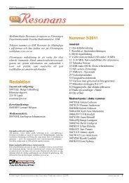
I bought <strong>the</strong> 12V Papst 4412 F/2GLLL IBL (IBL st<strong>and</strong>s for IchBinLeise)<br />
with only 16 dB(A) sound.<br />
This fan costs about 22 euro <strong>and</strong> is extremely silent!
Place <strong>the</strong> fan on <strong>the</strong> rear panel outlet. Direct its axis according to <strong>the</strong> air<br />
flow, so <strong>the</strong> fan would blow into <strong>the</strong> amplifier volume.<br />
I also bought four Noiseblocker NB-SLICS vibration absorbers to prevent<br />
tremble from <strong>the</strong> fan onto <strong>the</strong> cabinet <strong>of</strong> <strong>the</strong> <strong>A<strong>com</strong></strong> <strong>2000A</strong>, see <strong>the</strong> photo's<br />
below:
C A U T I O N!: Pay attention to <strong>the</strong> air flow direction as indicated<br />
on <strong>the</strong> fan case.<br />
The fan must suck air from <strong>the</strong> outside <strong>and</strong> force it into <strong>the</strong><br />
amplifier.<br />
Orient <strong>the</strong> leads in <strong>the</strong> shortest way to <strong>the</strong> inside.
Direct its axis with <strong>the</strong> dome facing inside <strong>the</strong> amplifier (in order not to<br />
touch <strong>the</strong> fan).<br />
Align its mounting holes with <strong>the</strong> holes <strong>of</strong> <strong>the</strong> rear panel <strong>and</strong> <strong>the</strong> fan<br />
outside.
In case that <strong>the</strong> shortest way is inconvenient, use <strong>the</strong> for this purpose<br />
provided aperture close to <strong>the</strong> fan, piercing <strong>the</strong> blanking cable gromet.
Place <strong>the</strong> metal grid on <strong>the</strong> iternal wall <strong>of</strong> <strong>the</strong> rear panel, against <strong>the</strong> fan.
Mount <strong>the</strong> air filter on <strong>the</strong> fan rear, using <strong>the</strong> remaining four M4x16mm<br />
bolts.<br />
Please note that it is very important to have <strong>the</strong> air filter installed since<br />
much more air will flow through <strong>the</strong> amplifier volume.
C A U T I O N!: Compare <strong>the</strong> type (DC or AC) <strong>and</strong> nominal voltage<br />
<strong>of</strong> <strong>the</strong> supplied fan with <strong>the</strong> indicated in Table 2-1,<br />
ACOM<strong>2000A</strong> Individual Data in your Operating Manual.<br />
If <strong>the</strong> fan is for 12V DC or 24V DC, connect it to <strong>the</strong> small PCB, located<br />
immediately below its aperture.<br />
Fan's positive lead, which is usually red, connect to <strong>the</strong> board pad<br />
indicated "+", <strong>and</strong> <strong>the</strong> negative lead - to <strong>the</strong> o<strong>the</strong>r indicated "-".<br />
If <strong>the</strong> nominal voltage <strong>of</strong> <strong>the</strong> supplied fan is different from that indicated<br />
in Table 2-1,<br />
you must open <strong>the</strong> cover below TUBE DECK; see <strong>the</strong> photo's above.
(Photo by <strong>A<strong>com</strong></strong>)
(Photo by <strong>A<strong>com</strong></strong>)
And <strong>the</strong>re, on <strong>the</strong> AIR SENSOR board, move <strong>the</strong> jumper for <strong>the</strong><br />
appropriate voltage: 12V or 24V.<br />
In my <strong>A<strong>com</strong></strong> <strong>2000A</strong> <strong>the</strong>re was no jumper as you can see on <strong>the</strong><br />
photo above!
C A U T I O N!:<br />
Where <strong>the</strong> yellow cross is signed on <strong>the</strong> photo above you have to scratch<br />
away <strong>the</strong> PCB-print with a little sharp knife.<br />
Use a multimeter to convince yourself that <strong>the</strong> PCB-print is fully scratched<br />
away.<br />
Then you can solder a bridge between <strong>the</strong> two round openings on <strong>the</strong> PCB,<br />
where you see <strong>the</strong> little yellow line on <strong>the</strong> photo above.<br />
I did it differently! You can see it on this two photo's below:
I soldered a three-pins holder on <strong>the</strong> PCB <strong>and</strong> put a jumper for 12V<br />
operation,<br />
in case ano<strong>the</strong>r fan (24V) is installed later in time.<br />
Again: do not forget to scratch away <strong>the</strong> PCB-print first!<br />
N O T E The external fan is running all <strong>the</strong> time while <strong>the</strong><br />
amplifier is ON.<br />
Using DC types is preferable since <strong>the</strong>y are controlled at two speed levels,<br />
depending on <strong>the</strong> exhaust air temperature.<br />
Running speed is accelerated above 90 degrees C (194F) <strong>and</strong> is<br />
automatically slowed down when <strong>the</strong> cooling air temperature drops below<br />
80 degrees C (176F).
Full temperature scale on <strong>the</strong> RCU is up to 130 degrees C (266F), each<br />
bar weights 10 degrees C (18F).<br />
The amplifier will work normally up to <strong>the</strong> scale end, <strong>and</strong> a ">" sign would<br />
appear if overflowed,<br />
in order to warn you about a too high temperature.<br />
A protection trips at 150 degrees C (302F) threshold.<br />
The absolute maximum plate temperature at <strong>the</strong> ceramic-to-heatsink<br />
junction is 200 degrees C (392F) as stated by <strong>the</strong> tube's producer<br />
Svetlana.<br />
If <strong>the</strong> exhaust air temperature is higher than 80 degrees C (176F) at <strong>the</strong><br />
moment you switch <strong>the</strong> amplifier <strong>of</strong>f,<br />
<strong>the</strong> tubes <strong>and</strong> external fan are instantly powered <strong>of</strong>f, but <strong>the</strong> internal<br />
blower would run long enough,<br />
until <strong>the</strong> exhaust air temperature drops below 80 degrees C (176F).<br />
A protection system monitors <strong>the</strong> air motion in <strong>the</strong> tube deck volume.<br />
This would prevent <strong>the</strong> control system <strong>of</strong> being let down if <strong>the</strong> blower<br />
stops (o<strong>the</strong>rwise it would measure a low-temperature but still-st<strong>and</strong>ing air<br />
above too hot tubes).<br />
You would get a "LOW AIRFLOW" message in such conditions in order to<br />
prevent tubes overheating.<br />
B. MODIFICATION OF THE <strong>EBS</strong> (Electronic<br />
Bias System) IN THE ACOM <strong>2000A</strong><br />
I did <strong>the</strong> <strong>modification</strong> which fully eliminates <strong>the</strong> <strong>EBS</strong> circuit.
With <strong>the</strong> addition <strong>of</strong> a capacitor only <strong>the</strong> time is increased,<br />
<strong>and</strong> with <strong>the</strong> addition <strong>of</strong> <strong>the</strong> jumper <strong>the</strong> action <strong>of</strong> <strong>the</strong> circuit for<br />
<strong>EBS</strong> is eliminated.<br />
This will connect <strong>the</strong> emitter <strong>of</strong> <strong>the</strong> transistor Q4 in order to fully<br />
block <strong>the</strong> <strong>EBS</strong> operation,<br />
i.e. <strong>the</strong> tubes will be operated with <strong>the</strong> high-level idling current<br />
always when <strong>the</strong> PTT is pressed,<br />
whe<strong>the</strong>r <strong>the</strong> RF drive is present or not.<br />
No additional capacitor will be needed in this case.
Put <strong>the</strong> <strong>A<strong>com</strong></strong> <strong>2000A</strong> upside down <strong>and</strong> remove <strong>the</strong> four screws directly<br />
behind <strong>the</strong> front panel.<br />
Put <strong>the</strong> <strong>A<strong>com</strong></strong> <strong>2000A</strong> on its feet <strong>and</strong> remove <strong>the</strong> two screws on <strong>the</strong> upper<br />
side <strong>of</strong> <strong>the</strong> front panel.
(Photo by <strong>A<strong>com</strong></strong>)
(Photo by <strong>A<strong>com</strong></strong>)
This is <strong>the</strong> Interface board in my <strong>A<strong>com</strong></strong> <strong>2000A</strong> (from August 2004)
Please look for Q4.
(Photo by <strong>A<strong>com</strong></strong>)<br />
Add a wire jumper between <strong>the</strong> via holes pointed by two yellow arrows as<br />
shown with a blue line in <strong>the</strong> picture.
First solder one side <strong>of</strong> a wire.
Then <strong>the</strong> o<strong>the</strong>r side <strong>and</strong> keep <strong>the</strong> lead (bridge) as short as possible.<br />
The <strong>EBS</strong> <strong>modification</strong> now is a fact.<br />
ATTENTION: when you use an older type <strong>A<strong>com</strong></strong> <strong>2000A</strong> (before 2002)<br />
please follow <strong>the</strong> <strong>modification</strong> as on <strong>the</strong> photo below:
(Photo by <strong>A<strong>com</strong></strong>)
Reinstall <strong>the</strong> power transformer <strong>and</strong> <strong>the</strong> cover <strong>of</strong> <strong>the</strong> amplifier.<br />
Observe <strong>the</strong> considerations from S.2-2 <strong>of</strong> <strong>the</strong> OPERATING MANUAL.<br />
In my case <strong>the</strong> <strong>EBS</strong> <strong>modification</strong> was a significantly improvement <strong>of</strong><br />
my transmitted audio!<br />
I have recordings <strong>of</strong> before <strong>and</strong> after <strong>the</strong> <strong>modification</strong>.<br />
So far I did not observe any increasement <strong>of</strong> <strong>the</strong> temperature.<br />
Please enjoy your modificated <strong>A<strong>com</strong></strong> <strong>2000A</strong>!<br />
73, Hans PA1HR.