Effect of Twisted-tape Inserts on Heat Transfer in a Tube - The Joint ...
Effect of Twisted-tape Inserts on Heat Transfer in a Tube - The Joint ...
Effect of Twisted-tape Inserts on Heat Transfer in a Tube - The Joint ...
- No tags were found...

Create successful ePaper yourself
Turn your PDF publications into a flip-book with our unique Google optimized e-Paper software.
<strong>The</strong> 2 nd Jo<strong>in</strong>t Internati<strong>on</strong>al C<strong>on</strong>ference <strong>on</strong> “Susta<strong>in</strong>able Energy and Envir<strong>on</strong>ment (SEE 2006)”<br />
A-030 (P) 21-23 November 2006, Bangkok, Thailand<br />
<str<strong>on</strong>g>Effect</str<strong>on</strong>g> <str<strong>on</strong>g>of</str<strong>on</strong>g> <str<strong>on</strong>g>Twisted</str<strong>on</strong>g>-<str<strong>on</strong>g>tape</str<strong>on</strong>g> <str<strong>on</strong>g>Inserts</str<strong>on</strong>g> <strong>on</strong> <strong>Heat</strong> <strong>Transfer</strong> <strong>in</strong> a <strong>Tube</strong><br />
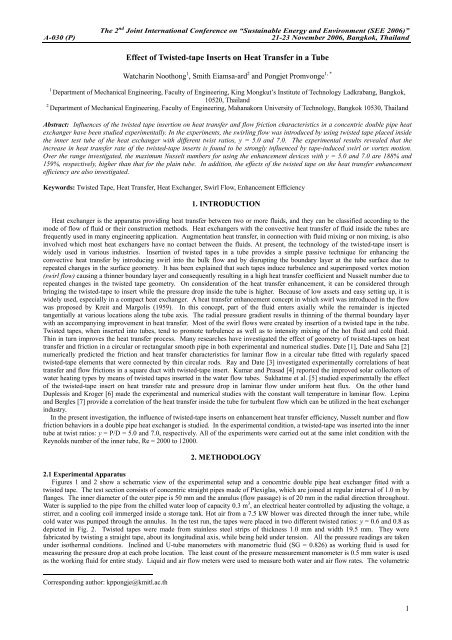
Watchar<strong>in</strong> Nooth<strong>on</strong>g 1 , Smith Eiamsa-ard 2 and P<strong>on</strong>gjet Promv<strong>on</strong>ge 1, *<br />
1<br />
Department <str<strong>on</strong>g>of</str<strong>on</strong>g> Mechanical Eng<strong>in</strong>eer<strong>in</strong>g, Faculty <str<strong>on</strong>g>of</str<strong>on</strong>g> Eng<strong>in</strong>eer<strong>in</strong>g, K<strong>in</strong>g M<strong>on</strong>gkut’s Institute <str<strong>on</strong>g>of</str<strong>on</strong>g> Technology Ladkrabang, Bangkok,<br />
10520, Thailand<br />
2<br />
Department <str<strong>on</strong>g>of</str<strong>on</strong>g> Mechanical Eng<strong>in</strong>eer<strong>in</strong>g, Faculty <str<strong>on</strong>g>of</str<strong>on</strong>g> Eng<strong>in</strong>eer<strong>in</strong>g, Mahanakorn University <str<strong>on</strong>g>of</str<strong>on</strong>g> Technology, Bangkok 10530, Thailand<br />
Abstract: Influences <str<strong>on</strong>g>of</str<strong>on</strong>g> the twisted <str<strong>on</strong>g>tape</str<strong>on</strong>g> <strong>in</strong>serti<strong>on</strong> <strong>on</strong> heat transfer and flow fricti<strong>on</strong> characteristics <strong>in</strong> a c<strong>on</strong>centric double pipe heat<br />
exchanger have been studied experimentally. In the experiments, the swirl<strong>in</strong>g flow was <strong>in</strong>troduced by us<strong>in</strong>g twisted <str<strong>on</strong>g>tape</str<strong>on</strong>g> placed <strong>in</strong>side<br />
the <strong>in</strong>ner test tube <str<strong>on</strong>g>of</str<strong>on</strong>g> the heat exchanger with different twist ratios, y = 5.0 and 7.0. <strong>The</strong> experimental results revealed that the<br />
<strong>in</strong>crease <strong>in</strong> heat transfer rate <str<strong>on</strong>g>of</str<strong>on</strong>g> the twisted-<str<strong>on</strong>g>tape</str<strong>on</strong>g> <strong>in</strong>serts is found to be str<strong>on</strong>gly <strong>in</strong>fluenced by <str<strong>on</strong>g>tape</str<strong>on</strong>g>-<strong>in</strong>duced swirl or vortex moti<strong>on</strong>.<br />
Over the range <strong>in</strong>vestigated, the maximum Nusselt numbers for us<strong>in</strong>g the enhancement devices with y = 5.0 and 7.0 are 188% and<br />
159%, respectively, higher than that for the pla<strong>in</strong> tube. In additi<strong>on</strong>, the effects <str<strong>on</strong>g>of</str<strong>on</strong>g> the twisted <str<strong>on</strong>g>tape</str<strong>on</strong>g> <strong>on</strong> the heat transfer enhancement<br />
efficiency are also <strong>in</strong>vestigated.<br />
Keywords: <str<strong>on</strong>g>Twisted</str<strong>on</strong>g> Tape, <strong>Heat</strong> <strong>Transfer</strong>, <strong>Heat</strong> Exchanger, Swirl Flow, Enhancement Efficiency<br />
1. INTRODUCTION<br />
<strong>Heat</strong> exchanger is the apparatus provid<strong>in</strong>g heat transfer between two or more fluids, and they can be classified accord<strong>in</strong>g to the<br />
mode <str<strong>on</strong>g>of</str<strong>on</strong>g> flow <str<strong>on</strong>g>of</str<strong>on</strong>g> fluid or their c<strong>on</strong>structi<strong>on</strong> methods. <strong>Heat</strong> exchangers with the c<strong>on</strong>vective heat transfer <str<strong>on</strong>g>of</str<strong>on</strong>g> fluid <strong>in</strong>side the tubes are<br />
frequently used <strong>in</strong> many eng<strong>in</strong>eer<strong>in</strong>g applicati<strong>on</strong>. Augmentati<strong>on</strong> heat transfer, <strong>in</strong> c<strong>on</strong>necti<strong>on</strong> with fluid mix<strong>in</strong>g or n<strong>on</strong> mix<strong>in</strong>g, is also<br />
<strong>in</strong>volved which most heat exchangers have no c<strong>on</strong>tact between the fluids. At present, the technology <str<strong>on</strong>g>of</str<strong>on</strong>g> the twisted-<str<strong>on</strong>g>tape</str<strong>on</strong>g> <strong>in</strong>sert is<br />
widely used <strong>in</strong> various <strong>in</strong>dustries. Inserti<strong>on</strong> <str<strong>on</strong>g>of</str<strong>on</strong>g> twisted <str<strong>on</strong>g>tape</str<strong>on</strong>g>s <strong>in</strong> a tube provides a simple passive technique for enhanc<strong>in</strong>g the<br />
c<strong>on</strong>vective heat transfer by <strong>in</strong>troduc<strong>in</strong>g swirl <strong>in</strong>to the bulk flow and by disrupt<strong>in</strong>g the boundary layer at the tube surface due to<br />
repeated changes <strong>in</strong> the surface geometry. It has been expla<strong>in</strong>ed that such <str<strong>on</strong>g>tape</str<strong>on</strong>g>s <strong>in</strong>duce turbulence and superimposed vortex moti<strong>on</strong><br />
(swirl flow) caus<strong>in</strong>g a th<strong>in</strong>ner boundary layer and c<strong>on</strong>sequently result<strong>in</strong>g <strong>in</strong> a high heat transfer coefficient and Nusselt number due to<br />
repeated changes <strong>in</strong> the twisted <str<strong>on</strong>g>tape</str<strong>on</strong>g> geometry. On c<strong>on</strong>siderati<strong>on</strong> <str<strong>on</strong>g>of</str<strong>on</strong>g> the heat transfer enhancement, it can be c<strong>on</strong>sidered through<br />
br<strong>in</strong>g<strong>in</strong>g the twisted-<str<strong>on</strong>g>tape</str<strong>on</strong>g> to <strong>in</strong>sert while the pressure drop <strong>in</strong>side the tube is higher. Because <str<strong>on</strong>g>of</str<strong>on</strong>g> low assets and easy sett<strong>in</strong>g up, it is<br />
widely used, especially <strong>in</strong> a compact heat exchanger. A heat transfer enhancement c<strong>on</strong>cept <strong>in</strong> which swirl was <strong>in</strong>troduced <strong>in</strong> the flow<br />
was proposed by Kreit and Margolis (1959). In this c<strong>on</strong>cept, part <str<strong>on</strong>g>of</str<strong>on</strong>g> the fluid enters axially while the rema<strong>in</strong>der is <strong>in</strong>jected<br />
tangentially at various locati<strong>on</strong>s al<strong>on</strong>g the tube axis. <strong>The</strong> radial pressure gradient results <strong>in</strong> th<strong>in</strong>n<strong>in</strong>g <str<strong>on</strong>g>of</str<strong>on</strong>g> the thermal boundary layer<br />
with an accompany<strong>in</strong>g improvement <strong>in</strong> heat transfer. Most <str<strong>on</strong>g>of</str<strong>on</strong>g> the swirl flows were created by <strong>in</strong>serti<strong>on</strong> <str<strong>on</strong>g>of</str<strong>on</strong>g> a twisted <str<strong>on</strong>g>tape</str<strong>on</strong>g> <strong>in</strong> the tube.<br />
<str<strong>on</strong>g>Twisted</str<strong>on</strong>g> <str<strong>on</strong>g>tape</str<strong>on</strong>g>s, when <strong>in</strong>serted <strong>in</strong>to tubes, tend to promote turbulence as well as to <strong>in</strong>tensity mix<strong>in</strong>g <str<strong>on</strong>g>of</str<strong>on</strong>g> the hot fluid and cold fluid.<br />
Th<strong>in</strong> <strong>in</strong> turn improves the heat transfer process. Many researches have <strong>in</strong>vestigated the effect <str<strong>on</strong>g>of</str<strong>on</strong>g> geometry <str<strong>on</strong>g>of</str<strong>on</strong>g> twisted-<str<strong>on</strong>g>tape</str<strong>on</strong>g>s <strong>on</strong> heat<br />
transfer and fricti<strong>on</strong> <strong>in</strong> a circular or rectangular smooth pipe <strong>in</strong> both experimental and numerical studies. Date [1], Date and Saha [2]<br />
numerically predicted the fricti<strong>on</strong> and heat transfer characteristics for lam<strong>in</strong>ar flow <strong>in</strong> a circular tube fitted with regularly spaced<br />
twisted-<str<strong>on</strong>g>tape</str<strong>on</strong>g> elements that were c<strong>on</strong>nected by th<strong>in</strong> circular rods. Ray and Date [3] <strong>in</strong>vestigated experimentally correlati<strong>on</strong>s <str<strong>on</strong>g>of</str<strong>on</strong>g> heat<br />
transfer and flow fricti<strong>on</strong>s <strong>in</strong> a square duct with twisted-<str<strong>on</strong>g>tape</str<strong>on</strong>g> <strong>in</strong>sert. Kumar and Prasad [4] reported the improved solar collectors <str<strong>on</strong>g>of</str<strong>on</strong>g><br />
water heat<strong>in</strong>g types by means <str<strong>on</strong>g>of</str<strong>on</strong>g> twisted <str<strong>on</strong>g>tape</str<strong>on</strong>g>s <strong>in</strong>serted <strong>in</strong> the water flow tubes. Sukhatme et al. [5] studied experimentally the effect<br />
<str<strong>on</strong>g>of</str<strong>on</strong>g> the twisted-<str<strong>on</strong>g>tape</str<strong>on</strong>g> <strong>in</strong>sert <strong>on</strong> heat transfer rate and pressure drop <strong>in</strong> lam<strong>in</strong>ar flow under uniform heat flux. On the other hand<br />
Duplessis and Kroger [6] made the experimental and numerical studies with the c<strong>on</strong>stant wall temperature <strong>in</strong> lam<strong>in</strong>ar flow. Lep<strong>in</strong>a<br />
and Bergles [7] provide a correlati<strong>on</strong> <str<strong>on</strong>g>of</str<strong>on</strong>g> the heat transfer <strong>in</strong>side the tube for turbulent flow which can be utilized <strong>in</strong> the heat exchanger<br />
<strong>in</strong>dustry.<br />
In the present <strong>in</strong>vestigati<strong>on</strong>, the <strong>in</strong>fluence <str<strong>on</strong>g>of</str<strong>on</strong>g> twisted-<str<strong>on</strong>g>tape</str<strong>on</strong>g> <strong>in</strong>serts <strong>on</strong> enhancement heat transfer efficiency, Nusselt number and flow<br />
fricti<strong>on</strong> behaviors <strong>in</strong> a double pipe heat exchanger is studied. In the experimental c<strong>on</strong>diti<strong>on</strong>, a twisted-<str<strong>on</strong>g>tape</str<strong>on</strong>g> was <strong>in</strong>serted <strong>in</strong>to the <strong>in</strong>ner<br />
tube at twist ratios: y = P/D = 5.0 and 7.0, respectively. All <str<strong>on</strong>g>of</str<strong>on</strong>g> the experiments were carried out at the same <strong>in</strong>let c<strong>on</strong>diti<strong>on</strong> with the<br />
Reynolds number <str<strong>on</strong>g>of</str<strong>on</strong>g> the <strong>in</strong>ner tube, Re = 2000 to 12000.<br />
2. METHODOLOGY<br />
2.1 Experimental Apparatus<br />
Figures 1 and 2 show a schematic view <str<strong>on</strong>g>of</str<strong>on</strong>g> the experimental setup and a c<strong>on</strong>centric double pipe heat exchanger fitted with a<br />
twisted <str<strong>on</strong>g>tape</str<strong>on</strong>g>. <strong>The</strong> test secti<strong>on</strong> c<strong>on</strong>sists <str<strong>on</strong>g>of</str<strong>on</strong>g> c<strong>on</strong>centric straight pipes made <str<strong>on</strong>g>of</str<strong>on</strong>g> Plexiglas, which are jo<strong>in</strong>ed at regular <strong>in</strong>terval <str<strong>on</strong>g>of</str<strong>on</strong>g> 1.0 m by<br />
flanges. <strong>The</strong> <strong>in</strong>ner diameter <str<strong>on</strong>g>of</str<strong>on</strong>g> the outer pipe is 50 mm and the annulus (flow passage) is <str<strong>on</strong>g>of</str<strong>on</strong>g> 20 mm <strong>in</strong> the radial directi<strong>on</strong> throughout.<br />
Water is supplied to the pipe from the chilled water loop <str<strong>on</strong>g>of</str<strong>on</strong>g> capacity 0.3 m 3 , an electrical heater c<strong>on</strong>trolled by adjust<strong>in</strong>g the voltage, a<br />
stirrer, and a cool<strong>in</strong>g coil immerged <strong>in</strong>side a storage tank. Hot air from a 7.5 kW blower was directed through the <strong>in</strong>ner tube, while<br />
cold water was pumped through the annulus. In the test run, the <str<strong>on</strong>g>tape</str<strong>on</strong>g>s were placed <strong>in</strong> two different twisted ratios: y = 0.6 and 0.8 as<br />
depicted <strong>in</strong> Fig. 2. <str<strong>on</strong>g>Twisted</str<strong>on</strong>g> <str<strong>on</strong>g>tape</str<strong>on</strong>g>s were made from sta<strong>in</strong>less steel strips <str<strong>on</strong>g>of</str<strong>on</strong>g> thickness 1.0 mm and width 19.5 mm. <strong>The</strong>y were<br />
fabricated by twist<strong>in</strong>g a straight <str<strong>on</strong>g>tape</str<strong>on</strong>g>, about its l<strong>on</strong>gitud<strong>in</strong>al axis, while be<strong>in</strong>g held under tensi<strong>on</strong>. All the pressure read<strong>in</strong>gs are taken<br />
under isothermal c<strong>on</strong>diti<strong>on</strong>s. Incl<strong>in</strong>ed and U-tube manometers with manometric fluid (SG = 0.826) as work<strong>in</strong>g fluid is used for<br />
measur<strong>in</strong>g the pressure drop at each probe locati<strong>on</strong>. <strong>The</strong> least count <str<strong>on</strong>g>of</str<strong>on</strong>g> the pressure measurement manometer is 0.5 mm water is used<br />
as the work<strong>in</strong>g fluid for entire study. Liquid and air flow meters were used to measure both water and air flow rates. <strong>The</strong> volumetric<br />
Corresp<strong>on</strong>d<strong>in</strong>g author: kpp<strong>on</strong>gje@kmitl.ac.th<br />
1
<strong>The</strong> 2 nd Jo<strong>in</strong>t Internati<strong>on</strong>al C<strong>on</strong>ference <strong>on</strong> “Susta<strong>in</strong>able Energy and Envir<strong>on</strong>ment (SEE 2006)”<br />
A-030 (P) 21-23 November 2006, Bangkok, Thailand<br />
flow rates <str<strong>on</strong>g>of</str<strong>on</strong>g> the hot air and cold water were adjusted by c<strong>on</strong>trol valves, situated before the <strong>in</strong>let ports. <strong>The</strong> <strong>in</strong>let air was heated by an<br />
adjustable electrical heater. Both the <strong>in</strong>let and outlet temperatures <str<strong>on</strong>g>of</str<strong>on</strong>g> the hot air and the cold water were measured by multi-channel<br />
with ir<strong>on</strong>-C<strong>on</strong>stantan thermocouple (type K). It was necessary to measure the temperature at 15 stati<strong>on</strong>s altogether at the outer<br />
surface <str<strong>on</strong>g>of</str<strong>on</strong>g> the <strong>in</strong>ner tube for f<strong>in</strong>d<strong>in</strong>g out the average Nusselt number.<br />
PC Computer<br />
Data Logger with<br />
<strong>The</strong>rmocouple type K<br />
Flow out<br />
C<strong>on</strong>centric <strong>Tube</strong> <strong>Heat</strong> Exchanger<br />
Flow <strong>in</strong><br />
(Hot air)<br />
Rotameter<br />
Flow out<br />
Rotameter<br />
Flow <strong>in</strong><br />
(Cold water)<br />
Chiller<br />
U-Manometer<br />
with Water<br />
Water<br />
Reservoir<br />
<strong>The</strong>rmostat<br />
with<br />
Electrical <strong>Heat</strong>er<br />
Centrifugal Pump<br />
Blower<br />
Fig. 1 Schematic diagrams <str<strong>on</strong>g>of</str<strong>on</strong>g> experimental apparatus<br />
2.2 Data reducti<strong>on</strong> equati<strong>on</strong>s<br />
For fluid flows <strong>in</strong> a c<strong>on</strong>centric tube heat exchanger, the heat transfer rate <str<strong>on</strong>g>of</str<strong>on</strong>g> the hot fluid (air) <strong>in</strong> the <strong>in</strong>ner tube can be expressed as:<br />
while the heat transfer <str<strong>on</strong>g>of</str<strong>on</strong>g> the cold fluid (water) for the outer tube is<br />
whereas,<br />
and<br />
Q = MC (T − T )<br />
(1)<br />
p<br />
o<br />
i<br />
Q = hA(T ~ T )<br />
(2)<br />
w −<br />
b<br />
Tb = (To<br />
+ Ti<br />
) / 2<br />
(3)<br />
∑<br />
T ~<br />
w = Tw<br />
/ 15<br />
(4)<br />
Where T w is the local wall temperature and evaluated at the outer wall surface <str<strong>on</strong>g>of</str<strong>on</strong>g> the <strong>in</strong>ner tube. It must be measured at the depth<br />
from the outer surface <str<strong>on</strong>g>of</str<strong>on</strong>g> 0.5 mm. <strong>The</strong> average wall temperatures are calculated from 15 po<strong>in</strong>ts, l<strong>in</strong>ed between the <strong>in</strong>let and exit <str<strong>on</strong>g>of</str<strong>on</strong>g><br />
the <strong>in</strong>ner tube. <strong>The</strong> average heat transfer coefficient is calculated from the energy balance are estimated as follows:<br />
h = MC (T T ) / A(T ~<br />
p o − i w − Tb<br />
)<br />
(5)<br />
<strong>The</strong> mean value <str<strong>on</strong>g>of</str<strong>on</strong>g> the Nusselt number is calculated based <strong>on</strong> the mean wall temperature w T and the local mean bulk fluid<br />
temperature.<br />
2
<strong>The</strong> 2 nd Jo<strong>in</strong>t Internati<strong>on</strong>al C<strong>on</strong>ference <strong>on</strong> “Susta<strong>in</strong>able Energy and Envir<strong>on</strong>ment (SEE 2006)”<br />
A-030 (P) 21-23 November 2006, Bangkok, Thailand<br />
hD<br />
Nu = (6)<br />
k<br />
Where, h and k are the mean heat transfer coefficient and mean thermal c<strong>on</strong>ductivity <str<strong>on</strong>g>of</str<strong>on</strong>g> the fluid, respectively, at all thermocouple<br />
locati<strong>on</strong>. <strong>The</strong> local thermal c<strong>on</strong>ductivity k <str<strong>on</strong>g>of</str<strong>on</strong>g> the fluid is calculated from the fluid properties at the local mean bulk fluid<br />
temperature. <strong>The</strong> Reynolds number is calculated based <strong>on</strong> the difference rate Q through the test secti<strong>on</strong>.<br />
Re = VD / v<br />
(7)<br />
Where v is the k<strong>in</strong>ematics viscosity <str<strong>on</strong>g>of</str<strong>on</strong>g> the work<strong>in</strong>g fluid. Fricti<strong>on</strong> factor can be written as follows:<br />
Flow out<br />
(Hot air)<br />
Dc<br />
D<br />
f =<br />
⎛<br />
⎜<br />
⎝<br />
L<br />
D<br />
∆P<br />
⎛ 2<br />
⎞ ⎞<br />
⎜<br />
V<br />
⎟ ρ ⎟<br />
⎠<br />
⎝<br />
2<br />
⎠<br />
Outer tube<br />
Inner tube<br />
Flow out<br />
(Cold water)<br />
Flow <strong>in</strong><br />
(Hot air)<br />
(8)<br />
L<br />
Flow <strong>in</strong><br />
(Cold water)<br />
Fig. 2 <strong>The</strong> <strong>in</strong>ner tube fitted with twisted <str<strong>on</strong>g>tape</str<strong>on</strong>g> at different twist ratios (y = 5.0 and 7.0)<br />
3. RESULTS AND DISCUSSION<br />
In the case <str<strong>on</strong>g>of</str<strong>on</strong>g> the twisted <str<strong>on</strong>g>tape</str<strong>on</strong>g> <strong>in</strong>serts, the means Nusselt numbers (<str<strong>on</strong>g>of</str<strong>on</strong>g> the <strong>in</strong>ner tube or hot air) <strong>in</strong>creased about 188% for y = 5.0<br />
and 159% for y = 7.0, when compared with the pla<strong>in</strong> tube. It was shown that the smaller <str<strong>on</strong>g>of</str<strong>on</strong>g> the twist ratio, the higher <strong>in</strong> mean<br />
Nusselts number as seen <strong>in</strong> Fig. 3(a). From the experimental results, it is clear that the twisted <str<strong>on</strong>g>tape</str<strong>on</strong>g> <strong>in</strong>serts caused swirl and pressure<br />
gradient <strong>in</strong> the radial directi<strong>on</strong>. <strong>The</strong> boundary layer al<strong>on</strong>g the tube wall would be th<strong>in</strong>ner with the <strong>in</strong>crease <str<strong>on</strong>g>of</str<strong>on</strong>g> radial swirl and<br />
pressure result<strong>in</strong>g <strong>in</strong>n more heat flow through the fluid. Moreover, swirl caused the flow to be turbulent, which led to even better<br />
c<strong>on</strong>vecti<strong>on</strong> heat transfer. From the figure, it is depicted that the effect <str<strong>on</strong>g>of</str<strong>on</strong>g> the twisted <str<strong>on</strong>g>tape</str<strong>on</strong>g> <strong>in</strong>serts decreased at low Reynolds numbers<br />
due to the weak swirl and low flow velocity. Thus, the <strong>in</strong>crease <strong>in</strong> Nusselt number was low at smaller Reynolds number, while it<br />
became greater at the higher Reynolds numbers. This phenomen<strong>on</strong> is related to the speed <str<strong>on</strong>g>of</str<strong>on</strong>g> the swirl-flow <str<strong>on</strong>g>of</str<strong>on</strong>g> the hot air and the<br />
results <str<strong>on</strong>g>of</str<strong>on</strong>g> the destructi<strong>on</strong> <str<strong>on</strong>g>of</str<strong>on</strong>g> the boundary layer level. Throughout the experimental results, it is obvious that the narrow twist ratio (y<br />
= 5.0) yielded the higher values <str<strong>on</strong>g>of</str<strong>on</strong>g> heat transfer than those were at the greater twist ratio (y = 7.0). This was due to the more violently<br />
swirl with the narrow twist ratio. <strong>The</strong> fricti<strong>on</strong> factor <strong>in</strong> the <strong>in</strong>ner tube varied with Reynolds number as shown <strong>in</strong> Fig. 3(b). It can be<br />
seen that the fricti<strong>on</strong>s are similar <strong>in</strong> trend for both the pla<strong>in</strong> tube and the tube fitted with twisted <str<strong>on</strong>g>tape</str<strong>on</strong>g> <strong>in</strong>serts. It was observed that the<br />
twisted <str<strong>on</strong>g>tape</str<strong>on</strong>g> <strong>in</strong>serts caused swirl<strong>in</strong>g flow <strong>in</strong>to the tube and leaded to high fricti<strong>on</strong> <str<strong>on</strong>g>of</str<strong>on</strong>g> 3.37 and 2.94 times <str<strong>on</strong>g>of</str<strong>on</strong>g> the pla<strong>in</strong> tube, for y = 5.0<br />
and 7.0, respectively <strong>in</strong> comparis<strong>on</strong> with the pla<strong>in</strong> tube. It can be seen that for the y = 5.0 gave smaller value <str<strong>on</strong>g>of</str<strong>on</strong>g> fricti<strong>on</strong> than that y =<br />
7.0 because the <strong>in</strong>tervals gave lower value <str<strong>on</strong>g>of</str<strong>on</strong>g> swirl<strong>in</strong>g flow than those <strong>in</strong> the case <str<strong>on</strong>g>of</str<strong>on</strong>g> small twist ratio.<br />
3
<strong>The</strong> 2 nd Jo<strong>in</strong>t Internati<strong>on</strong>al C<strong>on</strong>ference <strong>on</strong> “Susta<strong>in</strong>able Energy and Envir<strong>on</strong>ment (SEE 2006)”<br />
A-030 (P) 21-23 November 2006, Bangkok, Thailand<br />
120<br />
100<br />
(a)<br />
Nusselt number<br />
80<br />
60<br />
40<br />
20<br />
0<br />
0.5<br />
(b)<br />
Fricti<strong>on</strong> factor<br />
0.4<br />
0.3<br />
0.2<br />
y=6.0<br />
y=8.0<br />
Pla<strong>in</strong> tube<br />
0.1<br />
03<br />
(c)<br />
Enhancement efficiency<br />
2.5<br />
2<br />
1.5<br />
η =0.836Re 0.17 y -0.3<br />
1<br />
0 3000 6000 9000 12000 15000<br />
Reynolds number<br />
Fig. 3 Nusselts number, fricti<strong>on</strong> factor and enhancement efficiency versus Reynolds number for the tube fitted with twisted <str<strong>on</strong>g>tape</str<strong>on</strong>g> at<br />
different twist ratios (y)<br />
A useful comparis<strong>on</strong> between swirl and axial flow can be made by compar<strong>in</strong>g heat transfer coefficients at equal pump<strong>in</strong>g power,<br />
s<strong>in</strong>ce this is relevant to the operati<strong>on</strong> cost. For c<strong>on</strong>stant pump<strong>in</strong>g power;<br />
( V∆<br />
P ) p (V&<br />
∆P<br />
) t<br />
and the relati<strong>on</strong>ship between fricti<strong>on</strong> and Reynolds number can be expressed as:<br />
& = (9)<br />
3<br />
p<br />
3<br />
) t<br />
( f Re ) = ( f Re<br />
(10)<br />
4
<strong>The</strong> 2 nd Jo<strong>in</strong>t Internati<strong>on</strong>al C<strong>on</strong>ference <strong>on</strong> “Susta<strong>in</strong>able Energy and Envir<strong>on</strong>ment (SEE 2006)”<br />
A-030 (P) 21-23 November 2006, Bangkok, Thailand<br />
<strong>The</strong> enhancement efficiency (η ) at c<strong>on</strong>stant pump<strong>in</strong>g power is the ratio <str<strong>on</strong>g>of</str<strong>on</strong>g> the c<strong>on</strong>vective heat transfer coefficient <str<strong>on</strong>g>of</str<strong>on</strong>g> the tube with<br />
twisted <str<strong>on</strong>g>tape</str<strong>on</strong>g> to the pla<strong>in</strong> tube which can be written as follows:<br />
<strong>The</strong> enhancement efficiency for twisted <str<strong>on</strong>g>tape</str<strong>on</strong>g>s can be written as:<br />
ht<br />
η =<br />
(11)<br />
h<br />
p<br />
pp<br />
h<br />
0.17 −0.38<br />
η = = 0.836 Ret<br />
y<br />
(12)<br />
h<br />
t<br />
p<br />
pp<br />
Throughout the results <str<strong>on</strong>g>of</str<strong>on</strong>g> the experimentati<strong>on</strong>, it appears that use <str<strong>on</strong>g>of</str<strong>on</strong>g> the small twist ratio (y) leads to higher enhancement<br />
efficiency than that <str<strong>on</strong>g>of</str<strong>on</strong>g> the larger twisted ratio (y) as can be seen <strong>in</strong> Fig. 3(c). It can be seen that the enhancement efficiency <strong>in</strong>creases<br />
as the twisted ratio (y) decreases which generally higher at high Reynolds numbers for all twist ratios. This suggests that twisted<br />
<str<strong>on</strong>g>tape</str<strong>on</strong>g>s are feasible <strong>in</strong> terms <str<strong>on</strong>g>of</str<strong>on</strong>g> energy sav<strong>in</strong>g at higher Reynolds numbers. It is assumed that the performance improvement <strong>in</strong> the<br />
<strong>in</strong>tervals <str<strong>on</strong>g>of</str<strong>on</strong>g> Reynolds number and the sizes <str<strong>on</strong>g>of</str<strong>on</strong>g> the twisted <str<strong>on</strong>g>tape</str<strong>on</strong>g> is progressively develop<strong>in</strong>g. Thus it is possible to use the devices with<br />
the various styles <str<strong>on</strong>g>of</str<strong>on</strong>g> <str<strong>on</strong>g>tape</str<strong>on</strong>g>s <strong>in</strong>serts to reduce the pressure drop and possibly <strong>in</strong>crease the heat transfer.<br />
4. CONCLUSION<br />
Experimental <strong>in</strong>vestigati<strong>on</strong> <str<strong>on</strong>g>of</str<strong>on</strong>g> enhancement efficiency, heat transfer and fricti<strong>on</strong> factor characteristics <str<strong>on</strong>g>of</str<strong>on</strong>g> circular tube fitted with<br />
twisted <str<strong>on</strong>g>tape</str<strong>on</strong>g> <strong>in</strong>serts <str<strong>on</strong>g>of</str<strong>on</strong>g> different twist ratios has been studied. It can be observed that the swirl flow helps decrease the boundary layer<br />
thickness <str<strong>on</strong>g>of</str<strong>on</strong>g> the hot air flow and <strong>in</strong>crease residence time <str<strong>on</strong>g>of</str<strong>on</strong>g> hot air <strong>in</strong> the <strong>in</strong>ner tube. <strong>The</strong> enhancement efficiency and Nusselt number<br />
<strong>in</strong>creases with decreas<strong>in</strong>g the twist ratio and fricti<strong>on</strong> factor also <strong>in</strong>creases with decreas<strong>in</strong>g the twist ratio. <strong>The</strong> partiti<strong>on</strong><strong>in</strong>g and<br />
blockage <str<strong>on</strong>g>of</str<strong>on</strong>g> the tube flow cross-secti<strong>on</strong> by the <str<strong>on</strong>g>tape</str<strong>on</strong>g>, result<strong>in</strong>g <strong>in</strong> higher flow velocities. Sec<strong>on</strong>dary fluid moti<strong>on</strong> is generated by the<br />
<str<strong>on</strong>g>tape</str<strong>on</strong>g> twist, and the result<strong>in</strong>g twist mix<strong>in</strong>g improves the c<strong>on</strong>vecti<strong>on</strong> heat transfer.<br />
5. REFERENCES<br />
[1] Date, A.W. (1974) Predicti<strong>on</strong> <str<strong>on</strong>g>of</str<strong>on</strong>g> fully developed flow <strong>in</strong> a tube c<strong>on</strong>ta<strong>in</strong><strong>in</strong>g a twisted <str<strong>on</strong>g>tape</str<strong>on</strong>g>, Internati<strong>on</strong>al Journal <strong>Heat</strong> Mass<br />
<strong>Transfer</strong>, 17, pp. 845-859.<br />
[2] Date, A.W. and Saha, S.K. (1990) Numerical predicti<strong>on</strong> <str<strong>on</strong>g>of</str<strong>on</strong>g> lam<strong>in</strong>ar flow and heat transfer <strong>in</strong> a tube fitted with regularly spaced<br />
twisted-<str<strong>on</strong>g>tape</str<strong>on</strong>g> elements, Internati<strong>on</strong>al Journal <strong>Heat</strong> Fluid Flow, 11, pp. 346-354.<br />
[3] Ray, S. and Date, A.W. (2003) Fricti<strong>on</strong> and <strong>Heat</strong> <strong>Transfer</strong> Characteristics <str<strong>on</strong>g>of</str<strong>on</strong>g> Flow through Square Duct with <str<strong>on</strong>g>Twisted</str<strong>on</strong>g> Tape Insert,<br />
Internati<strong>on</strong>al Journal <strong>Heat</strong> and Mass <strong>Transfer</strong>, 46, pp. 889-902.<br />
[4] Kumar, A. and Prasad, B.N. (2000) Investigati<strong>on</strong> <str<strong>on</strong>g>of</str<strong>on</strong>g> twisted <str<strong>on</strong>g>tape</str<strong>on</strong>g> <strong>in</strong>serted solar water heaters-heat transfer, fricti<strong>on</strong> factor and<br />
thermal performance results, Renewable Energy Journal, 19, pp. 379-398.<br />
[5] Sukhatme, S.P., Gait<strong>on</strong>de, U.N., Shidore, C.S. and Kuncolienkar, R.S. (1987) Forced c<strong>on</strong>vecti<strong>on</strong> heat transfer to visous liqiuid<br />
<strong>in</strong> lam<strong>in</strong>ar flow <strong>in</strong> a tube with a twisted <str<strong>on</strong>g>tape</str<strong>on</strong>g>, Proced<strong>in</strong>g N<strong>in</strong>th Natl. <strong>Heat</strong> Mass <strong>Transfer</strong> C<strong>on</strong>ference, (Paper no. HMT 7-87)<br />
Indian Institute <str<strong>on</strong>g>of</str<strong>on</strong>g> Science, Bangalore, India, Part B, 1-7.<br />
[6] Duplessis, J.P. and Kroeger, D.G. (1983) Numerical predicti<strong>on</strong> <str<strong>on</strong>g>of</str<strong>on</strong>g> lam<strong>in</strong>ar flow with heat transfer <strong>in</strong> tube with a twisted <str<strong>on</strong>g>tape</str<strong>on</strong>g><br />
<strong>in</strong>sert, Proceed<strong>in</strong>g <str<strong>on</strong>g>of</str<strong>on</strong>g> the Internati<strong>on</strong>al C<strong>on</strong>ference <strong>on</strong> Numerical Methods <strong>in</strong> Lam<strong>in</strong>ar and Turbulent Flow, pp. 775-785.<br />
[7] Lep<strong>in</strong>a, R.F. and Bergles, A.E. (1969) <strong>Heat</strong> transfer and pressure drop <strong>in</strong> <str<strong>on</strong>g>tape</str<strong>on</strong>g>-generated swirl flow <str<strong>on</strong>g>of</str<strong>on</strong>g> s<strong>in</strong>gle-phase water, ASME<br />
Journal <strong>Heat</strong> <strong>Transfer</strong>, 91, pp. 434-442.<br />
5