MDC100-050101 - Anaheim Automation
MDC100-050101 - Anaheim Automation
MDC100-050101 - Anaheim Automation
- No tags were found...

Create successful ePaper yourself
Turn your PDF publications into a flip-book with our unique Google optimized e-Paper software.
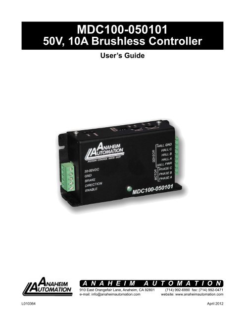
<strong>MDC100</strong>-<strong>050101</strong><br />
50V, 10A Brushless Controller<br />
User’s Guide<br />
A N A H E I M A U T O M A T I O N<br />
910 East Orangefair Lane, <strong>Anaheim</strong>, CA 92801<br />
e-mail: info@anaheimautomation.com<br />
(714) 992-6990 fax: (714) 992-0471<br />
website: www.anaheimautomation.com<br />
L010364<br />
April 2012
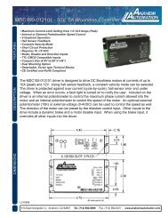
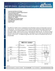
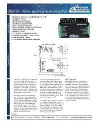
<strong>MDC100</strong>-<strong>050101</strong> Driver Features<br />
• Maximum Current Limit Setting from 1.0-10.0 Amps (peak)<br />
• Internal or External Potentiometer Speed Control<br />
• 2-Quadrant Operation<br />
• Hall Sensor Feedback<br />
• Constant Velocity Mode<br />
• Short Circuit Protection<br />
• Requires 20 - 50 VDC<br />
• Brake, Disable and Direction Inputs<br />
• TTL-CMOS Compatible Inputs<br />
• Compact Size (4.45”x2.66”x1.48”)<br />
• Dual Mounting Option<br />
• Detachable, Screw type Terminal Blocks<br />
• CE Certified and RoHS Compliant<br />
General Description<br />
The <strong>MDC100</strong>-<strong>050101</strong> driver is designed to drive DC brushless motors at currents of up to 10A (peak)<br />
and 50V. Using hall sensor feedback, a constant velocity mode can be selected. The driver is protected<br />
against over current cycle-by-cycle), hall sensor error and under voltage. When an error occurs, a fault<br />
light is turned on to notify the user. Included on the drive is an internal potentiometer to control the maximum<br />
phase current allowed into the motor and an internal potentiometer to control the speed of the motor.<br />
An optional external potentiometer (10K) or external voltage (0-4VDC) can be used to control the speed<br />
as well. The direction of the motor can be preset by the direction control input. Other inputs to the drive<br />
include a dynamic brake and a motor disable input. When using the brake input, it overrides all other<br />
inputs into the driver.<br />
Fault Protection<br />
This driver is equipped with a FAULT LED to alert the user of the following conditions.<br />
1. Invalid Sensor Input Code<br />
2. Enable Input at Logic 0<br />
3. Over Current. The driver is equipped with cycle-by-cycle current limiting or over current<br />
latch.<br />
4. Undervoltage Lockout activation at 9.1VDC for the input voltage and 4.5VDC for the<br />
Hall Sensor voltage.<br />
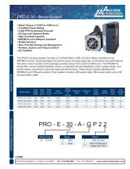
Ordering Information<br />
Part #<br />
<strong>MDC100</strong>-<strong>050101</strong><br />
PSA24V2.7A<br />
PSA40V4A<br />
PSA40V8A<br />
CBL-AA5420<br />
Description<br />
Featured BLDC driver 10A, 50V<br />
DC Power Supply 24VDC at 2.7 Amps<br />
DC Power Supply 40VDC at 4 Amps<br />
DC Power Supply 40VDC at 8 Amps<br />
Cable, 3 Pins 12in. Long, For External Pot<br />
L010364<br />
April 2012
Specifications<br />
Control Inputs: (TB2, Pins 3-5)<br />
TTL-CMOS Compatible<br />
Logic “0” = 0-0.8VDC<br />
Logic “1” = OPEN<br />
All three inputs (brake, enable and direction) are pulled up to through 40k ohm resistors.<br />
Freewheel: (TB2, Pin 5)<br />
Logic “1” (open) - Motor is Enabled<br />
Logic “0” - Motor is de-energized and will coast<br />
Direction Control: (TB2, Pin 4)<br />
Logic “1” (open) - Clockwise<br />
Logic “0” - Counterclockwise<br />
Brake: (TB2, Pin 3)<br />
Logic “1” (open) - Motor will not run and if running will decelerate rapidly<br />
Logic “0” - Motor will run<br />
Output Current Rating:<br />
Adjustable 1.0 - 10.0 amperes per phase maximum operating peak current<br />
(0.5 - 5.0 amperes per phase maximum operating continuous current)<br />
Power Requirements: (TB2, Pins 1 and 2)<br />
20VDC (min) - 50VDC (max)<br />
Operating Temperature<br />
Heat Sink: 0°-70° C<br />
Hall Sensor Power Output:<br />
6.25V @30mA maximum. Typical current draw from hall sensors in 20mA.<br />
All three Hall Sensor inputs are pulled up through 20K ohm resistors.<br />
The external speed control potentiometer must be 10K Ohms.<br />
Heating Considerations<br />
The temperature of the heat sink should never be allowed to rise above 70°C. If necessary, mount the unit<br />
to an additional heat sink or are should be blown across the heat sink to maintain suitable temperatures.<br />
L010364<br />
April 2012
Commutation Sequence<br />
Step<br />
Step<br />
1 2 3 4 5 6<br />
1 2 3 4 5 6<br />
Phase A + Z - - Z + Phase A - Z + + Z -<br />
Phase B Z + + Z - - Phase B Z - - Z + +<br />
Phase C - - Z + + Z Phase C + + Z - - Z<br />
Hall A 1 1 0 0 0 1 Hall A 1 1 0 0 0 1<br />
Hall B 0 1 1 1 0 0 Hall B 0 1 1 1 0 0<br />
Hall C 0 0 0 1 1 1 Hall C 0 0 0 1 1 1<br />
120° Hall Spacing Sequence Forward 120° Hall Spacing Sequence Reverse<br />
Step<br />
Step<br />
1 2 3 4 5 6<br />
1 2 3 4 5 6<br />
Phase A + Z - - Z + Phase A - Z + + Z -<br />
Phase B Z + + Z - - Phase B Z - - Z + +<br />
Phase C - - Z + + Z Phase C + + Z - - Z<br />
Hall A 1 1 1 0 0 0 Hall A 1 1 1 0 0 0<br />
Hall B 0 1 1 1 0 0 Hall B 0 1 1 1 0 0<br />
Hall C 0 0 1 1 1 0 Hall C 0 0 1 1 1 0<br />
60° Hall Spacing Sequence Forward 60° Hall Spacing Sequence Reverse<br />
+ = Top Transistor ON, Bottom Transistor OFF, Current flows into this wire<br />
- = Top Transistor OFF, Bottom Transistor ON, Current flows out of this wire<br />
Z = Top Transistor OFF, Bottom Transistor OFF, No current into or out of this wire (High Impedance)<br />
Motor Connection<br />
Refer to the hookup diagram for typical driver applications. When connecting a motor for the first time,<br />
connect the hall sensor wires (5 of them) to the driver. DO NOT CONNECT THE PHASES YET. Turn<br />
on power and rotate the motor by hand. If the RED FAULT LED comes on, the hall phases are incorrectly<br />
wired. If the RED FAULT LED does not come on then the hall wires are connected correctly.<br />
Power the unit down and proceed to connect the motor phases. If the motor does not run or runs<br />
erratically, power down and check the speed potentiometer and make sure the phases are connected<br />
correctly. There are six different ways to connect the phase wires, and normally only two will allow the<br />
motor to rotate, but only one is correct. If the direction of the motor is changed and the no-load current<br />
of the motor is approximately the same and the motor runs smoothly in both directions then the phase<br />
wires are correct.<br />
The wiring of the motor phases should be separated from the hall and input connections to not allow a<br />
possible source of interference.<br />
L010364<br />
April 2012
Terminal and Dip Switch Descriptions<br />
Pin # Description<br />
1 Phase A<br />
2 Phase B<br />
3 Phase C<br />
4 Hall Sensor Power<br />
5 Hall Sensor A<br />
6 Hall Sensor B<br />
7 Hall Sensor C<br />
8 Hall Sensor Ground<br />
TB1: Motor Terminals<br />
Pin # Description<br />
1 Power In (20-50VDC)<br />
2 Ground<br />
3 Brake<br />
4 Direction<br />
5 Enable<br />
TB2: Input Terminals<br />
Pin # Description<br />
1 +4.0V (Pot Top)<br />
2 Pot Wiper<br />
3 GND (Pot Bottom)<br />
JP3: 10K External Pot<br />
Jumper Functions<br />
Function JP4 JP1 JP2<br />
Constant Speed Mode (Closed Looped) Open --- ---<br />
Voltage Controlled Speed Mode (Open Loop) 1-2 --- ---<br />
60° Hall Sensor Spacing --- Open ---<br />
120° Hall Sensor Spacing --- 1-2 ---<br />
Internal Speed Control (R13) --- --- 1-2<br />
External Speed Control (JP3) --- --- 2-3<br />
Standard Product (Ready to Ship) 1-2 1-2 1-2<br />
Speed Adjust Setting<br />
There are two ways to set the speed on this drive. One is to use the on board potentiometer. The other<br />
is to use an external 10k potentiometer. To use the on board potentiometer, set jumper JP2 to position<br />
1-2 (default). To use the external 10K potentiometer, set jumper JP2 to position 2-3.<br />
The mating connector for the external 10K potentiometer is Molex part number 3-640440-3.<br />
Motor Enable<br />
The motor enable feature allows the de-energizing of the motor phases. An open input at this input<br />
causes the motor to run at the given speed, while a low at this input causes the motor to coast to a<br />
stop.<br />
Motor Brake<br />
The motor brake feature allows the stopping of a motor by shorting out the bottom drives of the three<br />
phases. A low at this input allows the motor to run, while an open input does not allow motor operation<br />
and if operating causes rapid deceleration.<br />
Motor Direction<br />
The motor direction feature allows the changing of the rotation of the motor. This input should not be<br />
changed while motion is in progress. An open input causes the motor to turn in the CW direction, while<br />
a low at this input causes the motor to turn in the CCW direction.<br />
L010364<br />
April 2012
Jumper/Potentiometer Location<br />
Typical Hookup Drawing<br />
L010364<br />
April 2012
Dimensions<br />
L010364<br />
April 2012
COPYRIGHT<br />
Copyright 2007 by <strong>Anaheim</strong> <strong>Automation</strong>. All rights reserved. No part of this publication may be reproduced,<br />
transmitted, transcribed, stored in a retrieval system, or translated into any language, in any form or by<br />
any means, electronic, mechanical, magnetic, optical, chemical, manual, or otherwise, without the prior<br />
written permission of <strong>Anaheim</strong> <strong>Automation</strong>, 910 E. Orangefair Lane, <strong>Anaheim</strong>, CA 92801.<br />
DISCLAIMER<br />
Though every effort has been made to supply complete and accurate information in this manual, the<br />
contents are subject to change without notice or obligation to inform the buyer. In no event will <strong>Anaheim</strong><br />
<strong>Automation</strong> be liable for direct, indirect, special, incidental, or consequential damages arising out<br />
of the use or inability to use the product or documentation.<br />
<strong>Anaheim</strong> <strong>Automation</strong>’s general policy does not recommend the use of its’ products in life support applications<br />
wherein a failure or malfunction of the product may directly threaten life or injury. Per <strong>Anaheim</strong> <strong>Automation</strong>’s<br />
Terms and Conditions, the user of <strong>Anaheim</strong> <strong>Automation</strong> products in life support applications assumes all<br />
risks of such use and indemnifies <strong>Anaheim</strong> <strong>Automation</strong> against all damages.<br />
LIMITED WARRANTY<br />
All <strong>Anaheim</strong> <strong>Automation</strong> products are warranted against defects in workmanship, materials and construction,<br />
when used under Normal Operating Conditions and when used in accordance with specifications. This<br />
warranty shall be in effect for a period of twelve months from the date of purchase or eighteen months<br />
from the date of manufacture, whichever comes first. Warranty provisions may be voided if products<br />
are subjected to physical modifications, damage, abuse, or misuse.<br />
<strong>Anaheim</strong> <strong>Automation</strong> will repair or replace at its’ option, any product which has been found to be defective<br />
and is within the warranty period, provided that the item is shipped freight prepaid, with previous authorization<br />
(RMA#) to <strong>Anaheim</strong> <strong>Automation</strong>’s plant in <strong>Anaheim</strong>, California.<br />
TECHNICAL SUPPORT<br />
If you should require technical support or if you have problems using any of the equipment covered by this<br />
manual, please read the manual completely to see if it will answer the questions you have. If you need<br />
assistance beyond what this manual can provide, contact your Local Distributor where you purchased the<br />
unit, or contact the factory direct.<br />
ANAHEIM AUTOMATION<br />
L010364<br />
April 2012