Mode de montage USDHC4 13 - Metaloterm
Mode de montage USDHC4 13 - Metaloterm
Mode de montage USDHC4 13 - Metaloterm

You also want an ePaper? Increase the reach of your titles
YUMPU automatically turns print PDFs into web optimized ePapers that Google loves.
<strong>Metaloterm</strong> ® USDHC 4 <strong>13</strong><br />
Montagehandleiding / Installation instructions / <strong>Mo<strong>de</strong></strong> <strong>de</strong> <strong>montage</strong><br />
NL EN FR<br />
Algemene voorschriften<br />
• Deafstandvankanalenendoorvoerentotbrandbaar<br />
materiaalmoetoveralminimaal50mmbedragen.<br />
• Alle elementen van zowel het luchttoevoer- als<br />
rookgasafvoersysteemmoetenminimaal30mmin<br />
elkaar steken en d.m.v. klemban<strong>de</strong>n of rvs<br />
parkers tegen losschieten geborgd wor<strong>de</strong>n.<br />
Toestelgebon<strong>de</strong>n voorschriften<br />
• Naast <strong>de</strong> bovenstaan<strong>de</strong> algemene voorschriften,<br />
zijn er toestelgebon<strong>de</strong>n voorschriften. Het<br />
betreft hier voornamelijk <strong>de</strong> toegestane<br />
minimum en maximum kanaallengte waarbij<br />
het toestel nog veilig functioneert.<br />
• Sommigetoestellenmetachteraansluitingkunnen<br />
rechtstreeks op <strong>de</strong> geveldoorvoer aangesloten<br />
wor<strong>de</strong>n. (zie <strong>de</strong> toestelgebon<strong>de</strong>n voorschriften)<br />
• An<strong>de</strong>retoestellenwor<strong>de</strong>naan<strong>de</strong>bovenzij<strong>de</strong>d.m.v.<br />
een speciaal aansluitstuk of rechtstreeks<br />
d.m.v. een concentrisch kanaal aangesloten op<br />
<strong>de</strong> geveldoorvoer.<br />
• De toestelgebon<strong>de</strong>n voorschriften kunt u<br />
opvragen bij <strong>de</strong> toestelfabrikant.<br />
Keuze van het uitmondingsgebied<br />
• Derookgasmondkan200°Cwor<strong>de</strong>n.Hetisdaarom<br />
belangrijkhetuitmondingsgebiedzotekiezen,dat<br />
mogelijk contact tussen rookgasmond en<br />
personen verme<strong>de</strong>n wordt.<br />
• De rookgassen kunnen bij dit type toestel oplopen<br />
tot ca. 400°C. Uitmon<strong>de</strong>n on<strong>de</strong>r overstekken en<br />
luifels kan gevaar opleveren door ophoping van<br />
hete verbrandingsgassen en is daarom niet<br />
toegestaan.<br />
• Voor uitmondingen in <strong>de</strong> nabijheid van een<br />
erfscheiding of ventilatieopening verwijzen wij<br />
naar <strong>de</strong> nationale voorschriften op dit gebied.<br />
(NL: NEN2757)<br />
Montagevoorbeel<strong>de</strong>n<br />
De on<strong>de</strong>rstaan<strong>de</strong> voorbeel<strong>de</strong>n zijn van algemene<br />
aard. De toestelfabrikant kan afwijken<strong>de</strong> bepalingen<br />
voorschrijven, <strong>de</strong>ze bepalingen hebben voorrang<br />
boven <strong>de</strong> algemene. Aan <strong>de</strong>ze voorbeel<strong>de</strong>n<br />
kunnen geen rechten ontleend wor<strong>de</strong>n.<br />
General instructions<br />
• Theminimumdistanceoffluesandterminalstoall<br />
combustible materials must be at least 50 mm.<br />
• Allpartsoftheairinletaswellasthegasfluemust,<br />
whenassembled,haveanoverlapofatleast30mm<br />
and then should be secured by means of a<br />
locking band or stainless steel parkers.<br />
Appliance-related instructions<br />
• Apart from the general instructions above, there<br />
are specific instructions in connection with the<br />
type of stove. This will contain the minimum and<br />
maximum allowed length of the flue system in<br />
relation to the safe working of the stove.<br />
• Certain types of stoves can be connected at the<br />
rear directly to the wall terminal. (see the<br />
specific instructions of the stove).<br />
• Other types of stoves are connected at the top,<br />
through an adapter or directly, to the concentric<br />
flue and then to the wall terminal.<br />
• Specific instructions related to the stove can<br />
be obtained from the stove manufacturer.<br />
Choosing the outlet area<br />
• The terminal can reach temperatures up to<br />
200°C. Therefore ensure that the location of<br />
the terminal prevents any direct contact<br />
between persons and the terminal.<br />
• The flue gases can reach temperatures up to<br />
400°C. Terminals that are located un<strong>de</strong>r<br />
screens or balconies can pose a threat due to<br />
the accumulation of hot gases, and therefore<br />
are not permitted.<br />
• In case of terminals that are close to neighbouring<br />
buildings or to ventilation openings we refer to<br />
the national or local regulations.<br />
Installation instructions<br />
The examples on the next pages are of general<br />
nature. Specific instructions issued by the stove<br />
manufacturer may differ; if so then the specific<br />
instructions will replace these general examples.<br />
The examples are for instructive use only, the manufacturer<br />
cannot be held liable for any damage<br />
that may arise from incorrect applications.<br />
Total Solutions in Flue Systems<br />
Prescriptions générales<br />
• Ladistanceminimale<strong>de</strong>sconduitsd’évacuation<strong>de</strong>s<br />
fuméeset<strong>de</strong>sterminauxparrapportauxmatériaux<br />
combustiblesdoitêtred’aumoins50mm.<br />
• Unrecouvrement<strong>de</strong>30mmauniveau<strong>de</strong>semboîtementsdoitêtreobservé,aprèsassemblage,entre<br />
chaqueélémentdusystèmeMETALOTERM ® US.<br />
Lesemboîtementsserontrenforcésparunebri<strong>de</strong><br />
<strong>de</strong>sécuritéouencoreàl’ai<strong>de</strong><strong>de</strong>visparkerinox.<br />
Prescriptions pour l’appareil<br />
• En complément <strong>de</strong>s instructions générales, les instructionsparticulières<strong>de</strong>raccor<strong>de</strong>mentsontfourniesavecl’insert.Ellesindiquentleslongueursmini<br />
et maxi du système d’évacuation <strong>de</strong>s fumées,<br />
afin d’assurer le bon fonctionnement <strong>de</strong> l’insert.<br />
• Certains modèles d’insert peuvent être raccordés<br />
directement à l’arrière <strong>de</strong> l’appareil avec le<br />
terminal horizontal <strong>USDHC4</strong> <strong>13</strong> (voir les<br />
instructions particulières <strong>de</strong> l’insert).<br />
• D’autres modèles sont raccordés sur le <strong>de</strong>ssus <strong>de</strong><br />
l’appareil, soit directement avec le système<br />
METALOTERM ® US, soit au moyen d’un adaptateur,<br />
via le terminal horizontal <strong>USDHC4</strong> <strong>13</strong>.<br />
• Les instructions particulières concernant<br />
l’insert sont disponibles auprès du fabricant.<br />
Choix <strong>de</strong> la zone <strong>de</strong> sortie<br />
• Le terminal peut atteindre <strong>de</strong>s températures <strong>de</strong><br />
200°C.Ilconvientdonc<strong>de</strong>s’assurerquelepublicne<br />
soit pas en contact direct avec le terminal.<br />
La température <strong>de</strong>s fumées atteignant jusqu’à<br />
400°C, la pose <strong>de</strong> terminaux sous une partie <strong>de</strong><br />
construction pouvant faire écran (balcon par<br />
exemple) est interdite, l’accumulation <strong>de</strong>s<br />
fumées représentant un danger.<br />
• Dans le cas <strong>de</strong> terminaux installés à proximité<br />
<strong>de</strong> bâtiments ou encore d’orifices <strong>de</strong> ventilation,<br />
il faut se référer aux réglementations<br />
locales et nationales.<br />
Conseils <strong>de</strong> pose<br />
• Les conseils <strong>de</strong> pose ci-après sont d’ordre général.<br />
Les instructions particulières données par le<br />
fabricant <strong>de</strong> l’insert peuvent différer <strong>de</strong>s conseils<br />
généraux, auquel cas il faudra tenir compte <strong>de</strong>s<br />
instructions particulières.<br />
• Les conseils <strong>de</strong> pose sont une ai<strong>de</strong> à la mise<br />
en place <strong>de</strong>s conduits. En aucun cas le fabricant<br />
ne pourra être tenu responsable <strong>de</strong>s dégâts<br />
éventuels occasionnées.
�<br />
�<br />
�<br />
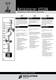
Fig. 1<br />
Fig. 2<br />
�<br />
� �<br />
�<br />
Ontop B.V.<br />
Postbus <strong>13</strong>5, 4330 AC Mid<strong>de</strong>lburg<br />
Ou<strong>de</strong>Veerseweg23,4332SHMid<strong>de</strong>lburg<br />
Ne<strong>de</strong>rland<br />
Tel.: +31 (0)118 689 900<br />
Fax: +31 (0)118 689 999<br />
E-mail: info.nl@metaloterm.com<br />
�<br />
NL EN FR<br />
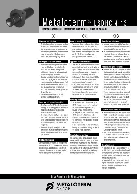
Doorvoer door onbrandbaar materiaal<br />
Zie fig. 1<br />
1. Monteer indien voorgeschreven een aansluitstuk<br />
(1) op het toestel. Type en co<strong>de</strong> volgens opgave<br />
van <strong>de</strong> fabrikant of in overleg met onze af<strong>de</strong>ling<br />
Verkoop.<br />
2.Plaats hierop een concentrisch kanaal (2)<br />
US 100/50/25 <strong>13</strong>. Let op <strong>de</strong> minimale en<br />
� �<br />
�<br />
maximale kanaallengte zoals voorgeschreven<br />
door <strong>de</strong> fabrikant.<br />
3.Plaats daarna een concentrische bocht (3)<br />
USB 90 <strong>13</strong> en bepaal plaats doorvoer.<br />
4.Gat in gevel maken zodanig dat <strong>de</strong> luchttoevoerhuls<br />
naar buiten afwatert. Hoek: 1 tot 3 gra<strong>de</strong>n of<br />
hellingspercentage: 2 tot 5 %.<br />
5.Lengte geveldoorvoer bepalen en indien nodig<br />
inkorten. Het inkorten van <strong>de</strong> luchttoevoerhuls<br />
(0,5 mm) gaat goed met een blikschaar. Het<br />
inkorten van <strong>de</strong> rookgasbuis (0,6 mm) gaat<br />
goed met een ijzerzaag. Slijpen wordt afgera<strong>de</strong>n<br />
i.v.m. het verbran<strong>de</strong>n van het rvs. Bramen en<br />
zaagsel verwij<strong>de</strong>ren.<br />
6.De geveldoorvoer (4) <strong>USDHC4</strong> <strong>13</strong> vanaf buiten<br />
door <strong>de</strong> gevel steken, met <strong>de</strong> punt met het logo<br />
rechtsboven op <strong>de</strong> concentrische bocht aansluiten<br />
en aan <strong>de</strong> gevel bevestigen. (Let op <strong>de</strong><br />
afwatering naar buiten van <strong>de</strong> luchttoevoerhuls.)<br />
7. Indien gewenst kan het gat aan <strong>de</strong> binnenzij<strong>de</strong> van<br />
<strong>de</strong> muur afgewerkt wor<strong>de</strong>n met een muurplaat<br />
(5) USMPG <strong>13</strong>. Deze is als optie te bestellen.<br />
Doorvoer door brandbaar materiaal<br />
In alle gevallen dient <strong>de</strong> doorvoer rondom 50 mm<br />
verwij<strong>de</strong>rd te zijn en te blijven van brandbaar<br />
materiaal. Praktisch kan dit op twee manieren<br />
uitgewerkt wor<strong>de</strong>n (zie fig. 2):<br />
1. Mantelbuis (1) van onbrandbaar materiaal<br />
diameter 300 mm gebruiken.<br />
2.Koker (2) van onbrandbaar materiaal maken, vierkant<br />
300 mm. Fabrikaat: Promatec 12 of Nobranda.<br />
In bei<strong>de</strong> gevallen centreerplaten (3) USCP <strong>13</strong><br />
of grote muurplaat USMPG <strong>13</strong> gebruiken voor<br />
centrering en afwerking.<br />
Ontop Abgastechnik GmbH<br />
Postfach <strong>13</strong>40, 51657 Wiehl<br />
Albert-Einstein-Straße 8, 51674 Wiehl<br />
Deutschland<br />
Telefon: +49 (0)22 61 7 08 –0<br />
Fax: +49 (0)22 61 7 08 90 / 7 08 95<br />
E-mail: info.<strong>de</strong>@metaloterm.com<br />
www.metaloterm.com<br />
Through non-combustible material<br />
See fig. 1<br />
1. Install,whenprescribed,anadapter(1)onthestove.<br />
Type and part number of the adapter according<br />
to the stove-manufacturers instructions or<br />
advised by our sales <strong>de</strong>partment.<br />
2.Connect the concentric flue (2), part no.<br />
US 100/50/25 <strong>13</strong>. Please respect the minimum<br />
and maximum length of the flue, as indicated by<br />
the stove manufacturer.<br />
3.Then connect an elbow (3) part no. USB 90 <strong>13</strong>, and<br />
mark the place of the terminal on the wall.<br />
4.Drill a hole in the wall and make sure that the air<br />
inlet is on a slight angle, thus allowing moisture<br />
to drain to the outsi<strong>de</strong>. Recommen<strong>de</strong>d angle<br />
1 - 3 <strong>de</strong>grees or 2 - 5% slope.<br />
5.Determine the required length of the terminal, and<br />
cut it when necessary. Cutting the air inlet<br />
(outer wall, 0.5 mm) is best done with a pair of<br />
tinner’s shears. Cutting the flue pipe (inner wall,<br />
0.6 mm) is best done with a metal saw. We do<br />
not recommend grinding off the pipes, because<br />
of the possible burning of the stainless steel.<br />
Remove burrs and sawdust.<br />
6.Connecttheterminal(4)fromtheoutsi<strong>de</strong>,andmake<br />
sure that the Ontop logo is at the upperright si<strong>de</strong> of<br />
the flue when connecting to the elbow. Fix at the<br />
outsi<strong>de</strong> wall. (Ensure the angle of the air inlet).<br />
7. Optionally, if required, the hole at the insi<strong>de</strong> of the<br />
wall can be covered with the wall cover (5),<br />
USMPG <strong>13</strong>. This part must be or<strong>de</strong>red seperately.<br />
Through combustible material<br />
In all circumstances the terminal must have a<br />
minimum distance of 50 mm to all combustible<br />
material. This can be realised in 2 different ways<br />
(see fig. 2):<br />
1. Use an extra tube (1) of non-combustible<br />
material, with a diameter of 300 mm.<br />
2.Install a square casing (2) of non combustible<br />
material, dimensions 300 x 300 mm.<br />
On inner and outer si<strong>de</strong> of the wall use a pair of<br />
centerplates (3), part number USCP <strong>13</strong> or large<br />
wall cover USMPG <strong>13</strong>, to center the terminal and<br />
to cover the hole.<br />
<strong>Metaloterm</strong> France S.A.R.L.<br />
18, rue <strong>de</strong>s Campanules<br />
77185 LOGNES<br />
France<br />
Téléphone: +33 (0)1 64 62 12 30<br />
Fax: +33 (0)1 64 62 11 08<br />
E-mail: info.fr@metaloterm.com<br />
<strong>Metaloterm</strong> Ontop Abgastechnik<br />
Erlenstraße 11a<br />
3612 Steffisburg<br />
die Schweiz<br />
Telefon: +41 (0)33 437 07 23<br />
Fax: +41 (0)33 437 07 26<br />
E-mail: info.ch@metaloterm.com<br />
Passage d’une faça<strong>de</strong> ininflammable<br />
Voir fig. 1<br />
1. Installer, lorsqu’il est prescrit, l’adaptateur (1) sur<br />
l’insert.Vouspouvezcontacterlefabricantouencore<br />
notre service commercial pour connaître le type<br />
et la référence <strong>de</strong> l’adaptateur.<br />
2.Raccor<strong>de</strong>rleconduitconcentriqueMETALOTERM ® US<br />
(2), avec les éléments US 100/50/25 <strong>13</strong>. Respecter<br />
les longueurs mini et maxi du système<br />
METALOTERM ® US, comme indiqué par le fabricant.<br />
3.Assembler le cou<strong>de</strong> 90° USB 90 <strong>13</strong> (3), et tracer<br />
au mur l’emplacement du terminal.<br />
4.Percer un trou dans le mur, en s’assurant que le<br />
terminal peut être mis en place avec une pente <strong>de</strong><br />
1 à 3 ° vers l’extérieur (afin <strong>de</strong> drainer l’humidité<br />
contenue dans l’air comburant vers l’extérieur).<br />
5.Déterminer la longueur requise du terminal, en la<br />
coupant si nécessaire, <strong>de</strong> la façon suivante:<br />
*Cisaille à métaux pour la paroi extérieure<br />
(épaisseur 0,5 mm)<br />
*Scie à métaux pour la paroi intérieure<br />
(épaisseur 0,6 mm)<br />
Nous déconseillons l’utilisation d’une disqueuse<br />
pour couper le terminal, l’échauffement<br />
provoqué étant trop important pour garantir la<br />
bonne tenue du matériel.<br />
6.Raccor<strong>de</strong>r le terminal <strong>USDHC4</strong> <strong>13</strong> (4) par<br />
l’extérieur et vérifier que le logo doit être<br />
positionné en haut à droite avant <strong>de</strong> l’assembler<br />
au cou<strong>de</strong> 90° (3). Ensuite, fixer l’ensemble sur<br />
le mur, en veillant à respecter la pente <strong>de</strong> 1 à 3°<br />
pour le terminal horizontal.<br />
7. Si besoin, la plaque <strong>de</strong> finition USMPG <strong>13</strong> (5)<br />
permet <strong>de</strong> couvrir l’espace entre le terminal et<br />
la réservation faite dans le mur, du côté intérieur.<br />
Cet article est en option et doit être commandé<br />
en plus du terminal <strong>USDHC4</strong> <strong>13</strong> (4).<br />
Passage d’une faça<strong>de</strong> inflammable<br />
Dans tous les cas <strong>de</strong> figure, la distance entre le<br />
terminal <strong>USDHC4</strong> <strong>13</strong> (4) et les matériaux combustibles<br />
ne doit pas être inférieure à 50 mm.<br />
Ceci peut se faire <strong>de</strong> 2 façons (voir fig.2) :<br />
1. Installer un tube en matériaux incombustible<br />
Ø 300 mm.<br />
2.Installer une cage rectangulaire en matériaux<br />
incombustible <strong>de</strong> dimensions 300 x 300 mm.<br />
Sur les parois intérieure et extérieure du mur,<br />
utiliser une paire <strong>de</strong> plaques <strong>de</strong> centrage USCP <strong>13</strong><br />
(3), ou plaque <strong>de</strong> finition large USMPG <strong>13</strong>, pour<br />
centrer le terminal et recouvrir l’espace entre<br />
celuici et la réservation faite dans le mur.<br />
Ontop Polska Sp. z o.o.<br />
ul. Rumiankowa 20<br />
87 - <strong>13</strong>4 Stary Toruń<br />
Polska<br />
Tel.: +48 (0)56 678 98 60<br />
GSM: +48 (0)602 157 467<br />
Fax: +48 (0)56 674 34 65<br />
E-mail: mgr@metaloterm.com<br />
<strong>USDHC4</strong><strong>montage</strong>_A<strong>13</strong>_<strong>13</strong><br />
juni 2008