Installation and Operation Guide - US Sunlight Corp
Installation and Operation Guide - US Sunlight Corp
Installation and Operation Guide - US Sunlight Corp

You also want an ePaper? Increase the reach of your titles
YUMPU automatically turns print PDFs into web optimized ePapers that Google loves.
<strong>Installation</strong> <strong>and</strong><br />
<strong>Operation</strong> <strong>Guide</strong><br />
Table of Contents<br />
1. What is included in this package<br />
2. Tools required<br />
3. <strong>Installation</strong> instructions<br />
4. Solar Controller settings <strong>and</strong> operation<br />
Tools Required<br />
- Philips Screwdriver<br />
Pre-Install Check<br />
A<br />
B<br />
D<br />
Tel: 877-50-<strong>US</strong>SUN<br />
www.ussunlight.com<br />
support@ussunlight.com<br />
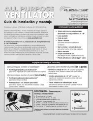
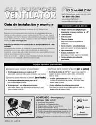
A Solar Controller Module<br />
B 4 - Mounting Screws<br />
C 2 - 8’ Cables<br />
D AC Power Adapter<br />
Please read the instructions before proceeding with installation. If your Solar Attic Fan has already been installed, please<br />
make sure the Solar Fan is working properly before installing the Solar Controller .<br />
Installing Solar Controller<br />
<br />
What is Included in the Box<br />
If your Solar Controller came bundled with an attic fan, install the fan first following the instructions included for that<br />
model fan. When the installation of the fan is complete, install Solar Controller. Note that Solar Controller is designed to<br />
work with U.S. <strong>Sunlight</strong> Solar Attic ventilation products. DO NOT ATTEMPT to connect Solar Controller to other solar fans.<br />
Solar Controller can be installed with or without the use of house electricity:<br />
St<strong>and</strong>ard <strong>Installation</strong><br />
When implementing the st<strong>and</strong>ard installation, Solar Controller will run only on power generated by the solar panel <strong>and</strong> will<br />
provide these functions:<br />
1. Reads attic temperature <strong>and</strong> relative humidity <strong>and</strong> displays them on the Controller Module.<br />
2. Option to engage or disengage the electronic humidistat <strong>and</strong> thermostat. Humidistat- Turns the fan on, providing<br />
solar power is available, at or above 75% humidity <strong>and</strong> off at or below 65% humdity. Thermostat - Turns the fan on,<br />
providing solar power is available, at or above 80oF <strong>and</strong> off at or below 77oF.<br />
(Note: These functions will be active only when the sun is available to generate electricity from the solar panel)<br />
<strong>Installation</strong> with use of House Electricity<br />
Installing Solar Controller with the AC Power Adapter will provide these additional benefits:<br />
4. Extends fan operation into the evening hours<br />
5. Allows fan to operate when no sun is available<br />
6. Intelligently limits the amount of house electricity to be used for adequate ventilation<br />
C<br />
Copyright 2012 <strong>US</strong> <strong>Sunlight</strong> <strong>Corp</strong>, Inc. SC5-M C01 ver 2
fig. 2b<br />
fig. 2a<br />
St<strong>and</strong>ard <strong>Installation</strong><br />
1. Bring the complete Solar Controller Module Kit to the attic.<br />
2. Install the Controller Module on a nearby rafter close to the underside of the roof with the<br />
provided mounting screws. (fig 2a & 2b) The Controller Module has vents on either side of the<br />
housing that allow the temperature <strong>and</strong> humidity sensors to work, so it is important to locate<br />
the Controller Box with at least 1 inch of space between it <strong>and</strong> the underside of the roof.<br />
(fig 3 & 4) For best results, locate the Controller Module near the fan opening as shown.<br />
Mounting within 2 to 3 feet of the motor is recommended. (fig 5)<br />
3. Unplug the 2 wire leads (red <strong>and</strong> black) from the<br />
motor. (fig 6) If your fan came with a thermal switch,<br />
unplug the wire coming in from the solar panel to the<br />
switch. (fig 7) The Controller Module will be replacing<br />
the function of this switch. You will not need the<br />
thermal switch <strong>and</strong> it can be discarded.<br />
fig. 8 fig. 9<br />
5. Take the other 8’ cable <strong>and</strong> connect the female leads to the solar connectors<br />
on the Controller Module (red to red <strong>and</strong> black to black) <strong>and</strong> connect the<br />
male leads into the female leads coming from the solar panel. (fig 10)<br />
WARNING: Fan will begin running as soon as sun hits the solar<br />
panel - keep fingers clear of the fan blades.<br />
6. The cable connectors have been designed to prevent incorrect connection. You<br />
will need to confirm the red wires are connected to the red wires <strong>and</strong> the black<br />
wires to the black wires, as shown. (fig 11)<br />
7. Provided there is sunlight to the solar panel, the LCD display is now activated<br />
<strong>and</strong> will read the current attic temperature <strong>and</strong> relative humidity. When the Solar<br />
Controller logic detects the fan in operation, the fan <strong>and</strong> solar LEDs will light up<br />
accordingly. This will take approximately 30 seconds.<br />
fig. 12a<br />
fig. 12b<br />
fig. 3 fig. 4 fig. 5<br />
fig. 6<br />
fig. 7<br />
4. Take one 8’ cable (included) <strong>and</strong> plug the<br />
female leads into the motor (red to red <strong>and</strong><br />
black to black) (fig 8) <strong>and</strong> connect the male<br />
leads to the fan connectors on the Controller<br />
Module. (fig 9) Note: It is important to connect<br />
the Controller Module to the motor<br />
BEFORE connecting to the solar panel.<br />
fig. 10<br />
fig. 11<br />
8. Use the included tie wraps <strong>and</strong> 1/4” or 1/2” coaxial staples, available<br />
from your local hardware store or builders’ supply, to secure the<br />
wiring harness to the rafter. (fig 12a & 12b)<br />
Solar Controller is now installed <strong>and</strong> running with power generated by the solar panel.
<strong>Installation</strong> with Use of Optional House Electricity<br />
To utilize the house electricity option with Solar Controller, connect the Controller Module to an AC outlet with the included<br />
AC Power Adapter. You may want to consult an electrician to decide on the best method for your situation. The AC<br />
Power Adapter works on a st<strong>and</strong>ard 110V outlet.<br />
DO NOT <strong>US</strong>E AN EXTENSION CORD FOR THIS CONNECTION.<br />
1. Complete steps 1~10 in the st<strong>and</strong>ard installation.<br />
2. Temporarily disconnect wiring to the solar connectors at the Controller Module.<br />
3. The AC Power Adapter comes with 4.5 ft. of cord. Verify the power source (outlet) is located<br />
within that distance. (fig 13)<br />
4. Connect the AC Power Adapter to the House Power/DC 12V port on the Controller Module as<br />
shown. (fig 14)<br />
5. Plug the AC Power Adapter into the power source (outlet). (fig 15) The Controller Module<br />
will display attic temperature <strong>and</strong> relative humidity in a few seconds.<br />
6. If necessary, use 1/4” or 1/2” coaxial staples to secure the wire to the rafter. (fig 16)<br />
7. Reconnect the wiring in step 2 to the solar connectors at the Controller Module.<br />
fig. 14<br />
fig. 13<br />
fig. 15 fig. 16<br />
Solar Controller will now utilize the solar panel <strong>and</strong> house electricity to optimize fan operation.<br />
Primary Power Source<br />
Power Source<br />
1. Whenever available, solar power is the default power source. On a typical day with proper sunlight, the fan will<br />
operate until sunset.<br />
2. If solar power is not available, the fan will not operate unless the Solar Controller is installed with the AC Power<br />
Adapter connected to house electricity. The fan will continue operation in the following pre-set mode for 6 hours:<br />
i. ON for 8 minutes <strong>and</strong> OFF for 22 minutes in a 30-minute period. This is the most effective air circulation<br />
frequency to keep the attic temperature close to the outside temperature<br />
ii. The fan will run for a maximum of 6 hours on intermittent house electricity.<br />
iii. The fan will run on solar power whenever solar power becomes available again.<br />
iv. After 6 hours of running on intermittent house electricity, the fan will be turned off for up to 12 hours, then<br />
turned back on, assuming solar power is not available during this period of time.<br />
Solar Fan with Solar Controller<br />
WITHOUT AC Adapter connected<br />
Solar Fan with Solar Controller<br />
WITH AC Adapter connected<br />
Daytime - with sufficient solar power Solar power Solar power<br />
Evening after sunset No power available Intermittent house electricity for 6 hours<br />
Addition of the Solar Controller Remote<br />
1. Provides convenient readout of fan status, attic temperature <strong>and</strong> attic humidity.<br />
2. Remotely manage fan’s operating logic by engaging or disengaging the thermal switch.<br />
3. One remote can monitor up to 3 fans.<br />
Additional Information<br />
Please visit our website at www.ussunlight.com for additional product information <strong>and</strong> FAQs. Or<br />
call 1-877-50-<strong>US</strong>SUN <strong>and</strong> one of our Customer Service Representatives will be able to help you.
W A R R A N T Y<br />
Manufacturer’s Limited Warranty<br />
U. S. <strong>Sunlight</strong> <strong>Corp</strong>. (“Manufacturer”) warrants that certain of its product components are free from defects of workmanship <strong>and</strong>/or materials<br />
for a period of time commencing on the date of original purchase <strong>and</strong> continuing as noted hereafter: (a) Solar Controller unit for a period of<br />
one (1) year (b) Solar Controller remote for a period of one (1) year.<br />
Disclaimer<br />
Except as expressly set forth herein, all Manufacturer’s products, including components thereof, are sold “AS IS” without warranty of<br />
merchantability, �tness for intended purpose, or other warranty, express or implied. In no event shall Manufacturer be liable for the loss of<br />
pro�ts, indirect, special, incidental, consequential or other similar damages, including but not limited to any claim or dem<strong>and</strong> arising out of the<br />
installation, furnishing, or functioning of a product or use by purchaser or any third party. The warranty terms <strong>and</strong> conditions detailed above<br />
do not extend to misuse, neglect, abuse, alteration, exposure to extreme weather conditions, lightning strikes, physical damage to any<br />
product, or damages caused by transportation or installation of any product. Manufacturer explicitly does not warrant any labor, shipping, or<br />
service fees incurred by purchaser for the replacement, repair, or exchange of any product or product components claimed under the above<br />
warranty terms <strong>and</strong> conditions.<br />
Warranty Claims<br />
Warranty claims shall be submitted in writing to Manufacturer at its principal place of business. Claims shall include a copy of the original<br />
purchase invoice, purchaser’s name, address, telephone number, <strong>and</strong> e-mail address, <strong>and</strong> such other particulars as are necessary to<br />
describe the claimed defect. If requested by Manufacturer, purchaser shall ship the claimed defective component(s) to Manufacturer’s<br />
principal place of business, FOB destination, freight prepaid, for evaluation. As to any product component determined by Manufacturer to<br />
contain a defect covered by its warranty, Manufacturer reserves the right, at its discretion, to repair or replace the defective component, or<br />
rebate a portion of the purchase price prorated based on the balance of the warranty term.<br />
General<br />
This limited warranty contains all of the terms <strong>and</strong> conditions of Manufacturer’s warranty of the purchased product <strong>and</strong> its components. No<br />
representation, arrangement, or agreement not appearing herein shall be binding on Manufacturer. This limited warranty is issued in <strong>and</strong> shall<br />
be governed by the laws of the State of California.<br />
� CUT HERE<br />
R E G I S T R A T I O N<br />
WE WOULD LOVE TO HEAR FROM YOU!<br />
To register please visit our website: www.ussunlight.com<br />
or simply �ll out this form <strong>and</strong> mail to:<br />
923 Tahoe Blvd. Suite 110 | Incline Village, Nevada 89451<br />
Name ________________________________________________________Phone________________________________________<br />
Address ___________________________________________________________________________________________________<br />
City __________________________________________________________ State ______________ Zip _____________________<br />
Email _____________________________________________________ Would you like to be included in our newsletter? Y or N<br />
Product Name __________________________________________ Date of Purchase ___________________________________<br />
Purchased From ______________________ Name of Installer _____________________________________________ (self )<br />
Phone # of Installer ___________________ How satis�ed are you with the install? Not Satis�ed Somewhat Very<br />
Comments ____________________________________________________________________________________________