Servo Valves - Yuken Hidrolik Türkiye
Servo Valves - Yuken Hidrolik Türkiye
Servo Valves - Yuken Hidrolik Türkiye

You also want an ePaper? Increase the reach of your titles
YUMPU automatically turns print PDFs into web optimized ePapers that Google loves.
I<br />
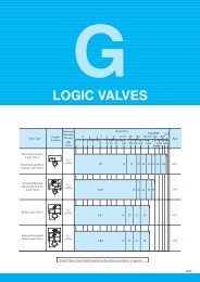
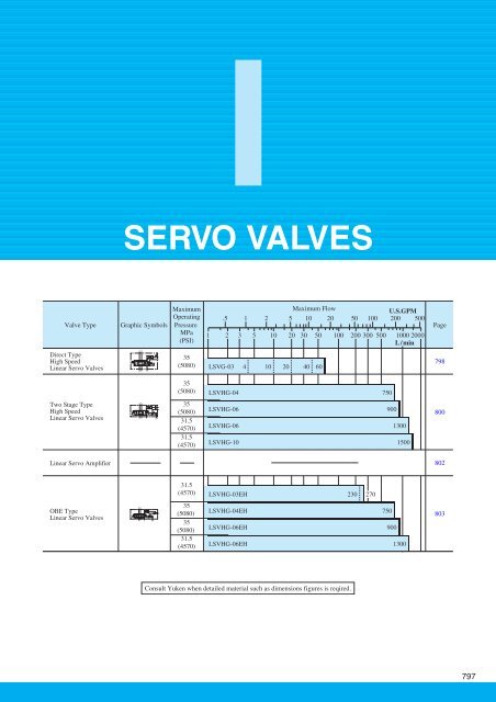
SERVO VALVES<br />
Valve Type<br />
Graphic Symbols<br />
Maximum<br />
Operating<br />
Pressure<br />
MPa<br />
(PSI)<br />
Maximum Flow<br />
U.S.GPM<br />
.5 1 2 5 10 20 50 100 200 500<br />
1 2 3 5 10 20 30 50 100 200 300 500 1000 2000<br />
L/min<br />
Page<br />
Direct Type<br />
High Speed<br />
Linear <strong>Servo</strong> <strong>Valves</strong><br />
A B<br />
PT<br />
Y<br />
35<br />
(5080)<br />
LSVG-03 4 10 20 40 60<br />
798<br />
35<br />
(5080)<br />
LSVHG-04 750<br />
Two Stage Type<br />
High Speed<br />
Linear <strong>Servo</strong> <strong>Valves</strong><br />
A B<br />
P T<br />
Y<br />
DR<br />
35<br />
(5080)<br />
31.5<br />
(4570)<br />
31.5<br />
(4570)<br />
LSVHG-06 900<br />
LSVHG-06 1300<br />
LSVHG-10 1500<br />
800<br />
Linear <strong>Servo</strong> Amplifier<br />
802<br />
31.5<br />
(4570)<br />
LSVHG-03EH 230 270<br />
OBE Type<br />
Linear <strong>Servo</strong> <strong>Valves</strong><br />
A B<br />
P T<br />
Y<br />
DR<br />
35<br />
(5080)<br />
35<br />
(5080)<br />
31.5<br />
(4570)<br />
LSVHG-04EH 750<br />
LSVHG-06EH 900<br />
LSVHG-06EH 1300<br />
803<br />
Consult <strong>Yuken</strong> when detailed material such as dimensions figures is reqired.<br />
797
High Speed Linear <strong>Servo</strong> <strong>Valves</strong><br />
High-speed linear servo valves have outstanding features of high response and exceptional contamination resistance.<br />
These features are achieved by the compact and powerful linear motor which directly drives the spool and gives electric<br />
feedback of the spool position. These valves have garnered an excellent reputation since their launch by <strong>Yuken</strong> in 2001.<br />
Direct type LSVG-03 and two stage type LSVHG-04/06/10(which use the LSVG-03 as a pilot) are available.<br />
Direct Type High Speed Linear <strong>Servo</strong> <strong>Valves</strong><br />
High accuracy<br />
These valves have a low hysteresis of 0.1 % or less, achieving high accuracy.<br />
They allow the main unit to operate with much higher repeatability.<br />
High response characteristics<br />
The valves provide significantly high levels of step and frequency responses,<br />
which are typically used as measures of response characteristics; the step<br />
response is 2 ms (0 100 %)*, and the frequency response is 450 Hz/- 90°<br />
(± 25 % amplitude)*. Thus, the valves ensure that the main unit can achieve<br />
unprecedented high response.<br />
(*: Representative values)<br />
Excellent vibration-proof characteristics<br />
With a simple structure, the valves offer high vibration resistance.<br />
Excellent contamination resistance<br />
The valves are also featured by excellent contamination resistance since they<br />
have a simple structure that directly connects the linear motor moving coil,<br />
the spool, and the position sensor. Compared to conventional servo valves for<br />
which the permissible contamination level is up to NAS 1638 class 7, the<br />
direct type linear servo valves can accept the contamination level of up to<br />
NAS 1638 class 10. These valves can contribute to greatly reducing the cost<br />
of fluid management.<br />
Graphic Symbol<br />
AB<br />
Model Number Deignation<br />
PT<br />
Y<br />
F- LSVG -03 -40 -R -10<br />
Special Seals<br />
Series<br />
Number<br />
Valve<br />
Size<br />
Rated Flow<br />
@∆P = 7 MPa<br />
(@∆P = 1020 PSI)<br />
Cable Departure<br />
Direction<br />
Design<br />
Number<br />
F<br />
Special Seals<br />
for Phosphate<br />
Ester Type<br />
Fluid (Omit if<br />
not required).<br />
LSVG:<br />
Direct Type<br />
High Speed<br />
Linear <strong>Servo</strong><br />
<strong>Valves</strong><br />
03<br />
4= 4 L/mi n ( 1.06 U. S. GP M)<br />
10=10 L/mi n ( 2.64 U. S. GP M)<br />
20=20 L/mi n ( 5.28 U. S. GP M)<br />
40=40 L/mi n (10.57 U. S. GP M)<br />
60=60 L/mi n (15.85 U. S. GP M)<br />
(Viewed from the<br />
linear motor side)<br />
None:<br />
Upper (Standard)<br />
R: Right<br />
L: Left<br />
10<br />
798<br />
Direct Type High Speed Linear <strong>Servo</strong> <strong>Valves</strong>
SERVO VALVES<br />
Specifications<br />
The specifications below are for use with a 48 VDC type exclusive amplifier; for use with a 24 VDC type amplifier,<br />
see the values in parentheses { }.<br />
Description<br />
Model Numbers<br />
Rated Flow @∆P = 7 MPa (1020 PSI) (1)<br />
Max. Operating Pressure<br />
Proof Pres. at Return Port<br />
Drain Port (Y) Permissible Back Pres. (2)<br />
Null Leakage @Ps = 14 MPa (2030 PSI)<br />
32 mm 2 /s (150 SSU)<br />
Hysteresis<br />
Step Response (0 100 %, Typical) (3)<br />
Frequency Response Gain: - 3 dB<br />
(± 25 % Amplitude,<br />
Typical) (3)<br />
Phase: - 90°<br />
Vibration Proof (4)<br />
Protection<br />
Ambient Temperature<br />
Spool Type<br />
Spool Stroke to Stops<br />
Linear Motor Current<br />
Specification Coil Resistance<br />
Mass<br />
Applicable <strong>Servo</strong> Amplifier<br />
LSVG-03-4/10/20/40<br />
4, 10, 20, 40 L/min<br />
(1.06, 2.64, 5.28, 10.57 U. S. GPM)<br />
35 MPa (5080 PSI)<br />
35 MPa (5080 PSI)<br />
0.05 MPa (7 PSI)<br />
2 ms {3 ms}<br />
1.7 L/min (.45 U.S. GPM) or less<br />
0.1 % or less<br />
LSVG-03-60<br />
60 L/min<br />
(15.85 U. S. GPM)<br />
3 ms {4 ms}<br />
350 Hz {300 Hz}<br />
330 Hz {240 Hz}<br />
450 Hz {370 Hz}<br />
410 Hz {330 Hz}<br />
Frequency: 10 - 60 Hz, Amplitude: 4 mm (.157 in.), Acceleration: 7.8 - 282 m/s 2 (25.6 to 925 ft./s 2 )<br />
Frequency: 61 - 2000 Hz, Amplitude: 4 - 0.0038 mm (.157 - .00015 in.), Acceleration: 294 m/s 2 (965 ft./s 2 )<br />
IP 64<br />
- 15 to + 60 °C (5 to 140°F)<br />
Neutral / Zero Lap<br />
± 0.5 mm (± .0197 inches)<br />
± 7.5 mm (± .0295 inches)<br />
2 A [Max. 6 A]<br />
4.5 Ω [at 20 °C (68 °F)]<br />
5 kg (11.0 lbs.)<br />
AMLS-A-D* - * -10<br />
AMLS-B-D* - * -10<br />
Note: (1) Use the valves so that the relationship between the valve pressure difference and the flow rate, as specified below in “Range of Flow Control”<br />
is met.<br />
(2) Back pressure at the drain port (Y) should be 0.05 MPa (7 PSI) or less and not be a negative pressure.<br />
(3) This value is measured for each valve; it may differ depending on the actual circuit.<br />
(4) There are restrictions on the mounting position; consult <strong>Yuken</strong> for details.<br />
Range of Flow Control<br />
Control Method: 4-Way Valve<br />
AB<br />
Control Method: 3-Way Valve<br />
A<br />
I<br />
Controlled Flow<br />
L/min<br />
100<br />
50<br />
30<br />
20<br />
10<br />
5<br />
3<br />
2<br />
PT<br />
Y<br />
Controlled Flow<br />
L/min<br />
100<br />
50<br />
30<br />
20<br />
10<br />
5<br />
3<br />
2<br />
PT<br />
Y<br />
LSVG-03-40-<br />
LSVG-03-20-<br />
LSVG-03-10-<br />
LSVG-03-4-<br />
LSVG-03-60-<br />
LSVG-03-40-<br />
LSVG-03-20-<br />
LSVG-03-10-<br />
LSVG-03-4-<br />
LSVG-03-60-<br />
Direct Type<br />
High Speed Linear <strong>Servo</strong> <strong>Valves</strong><br />
1<br />
1 2 3 5 10 20 35<br />
Pressure Difference MPa<br />
1<br />
1 2 3 5 10 20 35<br />
Pressure Difference MPa<br />
Direct Type High Speed Linear <strong>Servo</strong> <strong>Valves</strong><br />
799
Two Stage Type High Speed Linear <strong>Servo</strong> <strong>Valves</strong><br />
Two stage type linear servo valves are a type of high-flow servo valve<br />
that has a direct type high-speed linear servo valve in its pilot stage to<br />
drive the main spool.<br />
These valves control the positions of the pilot and main spools with<br />
electrical feedback, achieving high accuracy and response.<br />
High flow<br />
The valves consist of two stages to provide a high flow rate [Rated<br />
flow at ∆P = 7 MPa (1020 PSI): 750 to 1500 L/min (198 to 396<br />
U.S.GPM)].<br />
High accuracy<br />
The valves have a low hysteresis of 0.1 % or less, achieving high<br />
accuracy. They allow the main unit to operate with much higher<br />
repeatability.<br />
High response characteristics<br />
The valves provide significantly high levels of step and frequency<br />
responses, which are typically used as measures of response<br />
characteristics; the step response is 8 ms (0 100 %), and the frequency<br />
response is 100 Hz/- 90° (± 25 % amplitude) (Representative values<br />
for LSVHG-10-1500). Thus, the valves ensure the achievement of<br />
unprecedented high response.<br />
A B<br />
Graphic Symbols<br />
A B<br />
Excellent contamination resistance<br />
As is the case with the direct type linear servo valves, the permissible<br />
level of fluid contamination for these valves is up to NAS 1638 class<br />
10.<br />
P T<br />
Int. Pilot – Ext. Drain<br />
A B<br />
Y<br />
DR<br />
P T<br />
DR<br />
Int. Pilot – Int. Drain<br />
A B<br />
Model Number Deignation<br />
P T<br />
Y<br />
Ext. Pilot – Ext. Drain<br />
Note) The symbols above indicate<br />
the spool types "2" and "2P".<br />
The graphic symbol of the<br />
spool type "40" is shown on<br />
the right (external pilot/<br />
internal drain type).<br />
X<br />
DR<br />
P T X DR<br />
Ext. Pilot – Int. Drain<br />
A B<br />
P T<br />
X<br />
DR<br />
F- LSVHG -06 -900 -2P -E T -R -10<br />
Special<br />
Seals<br />
Series<br />
Number<br />
Valve<br />
Size<br />
Rated Flow<br />
@∆P = 7 MPa<br />
(@∆P = 1020 PSI)<br />
Spool<br />
Type<br />
Pilot<br />
Connection<br />
Drain<br />
Connection<br />
Cable<br />
Departure<br />
Direction<br />
Design<br />
Number<br />
F:<br />
Special Seals<br />
for Phosphate<br />
Ester Type<br />
Fluid (Omit if<br />
not required).<br />
LSVHG:<br />
Two Stage Type<br />
High Speed<br />
Linear <strong>Servo</strong><br />
<strong>Valves</strong><br />
04<br />
06<br />
10<br />
750: 750 L/min<br />
(198 U. S. GPM)<br />
900: 900 L/min<br />
(238 U. S. GPM)<br />
1300: 1300 L/min<br />
(343 U. S. GPM)<br />
1500: 1500 L/min<br />
(396 U. S. GPM)<br />
2: 10 % Overlap<br />
40: Open Centre<br />
A, B & T<br />
2P: Zero Lap<br />
(Dual Flow Gain)<br />
None:<br />
Internal<br />
Pilot<br />
E:<br />
External<br />
Pilot<br />
None:<br />
External<br />
Pilot<br />
T:<br />
Internal<br />
Pilot<br />
(Viewed from<br />
the linear<br />
motor side)<br />
None:<br />
Upper (Standard)<br />
R: Right<br />
L: Left<br />
10<br />
10<br />
10<br />
800<br />
Two Stage Type High Speed Linear <strong>Servo</strong> <strong>Valves</strong>
SERVO VALVES<br />
Specifications<br />
The specifications below are for use with a DC 48 V type exclusive amplifier; for use with a DC 24 V type amplifier,<br />
see the values in parentheses { }.<br />
Description<br />
Rated Flow<br />
Max. Operating Pressure<br />
Model Numbers<br />
∆P = 7 MPa (1020 PSI)<br />
(4-Way Valve)<br />
∆P = 0.5 MPa (73 PSI)<br />
(Per Land)<br />
Proof Pres.<br />
External Drain<br />
at Return Port Internal Drain (1)<br />
Drain Port (DR Port) Permissible<br />
Back Pressure (2)<br />
Pilot Pressure (3)<br />
Pilot Flow Rate (4)<br />
Max. Leakage<br />
Ps = Pp = 14 MPa<br />
(2030 PSI)<br />
@ Visocity:<br />
32 mm 2 /s<br />
(150 SSU)<br />
Hysteresis<br />
L/min (U. S. GPM)<br />
Pilot Valve<br />
- 2 -<br />
Main Spool<br />
- 40 -<br />
Valve Type<br />
- 2P -<br />
LSVHG-04-750<br />
750 L/min<br />
{198 U. S. GPM}<br />
283 L/min<br />
{74.8 U. S. GPM}<br />
35 MPa<br />
(5080 PSI)<br />
31.5 MPa<br />
(4570 PSI)<br />
27 (7.1) or more<br />
{22 (5.8)} or more<br />
0.8 L/min<br />
(.21 U. S. GPM)<br />
1.6 L/min<br />
(.42 U. S. GPM)<br />
6.8 L/min<br />
(1.80 U. S. GPM)<br />
LSVHG-06-900<br />
0.1 % or less<br />
LSVHG-06-1300<br />
900 L/min<br />
{238 U. S. GPM}<br />
1300 L/min<br />
{343 U. S. GPM}<br />
340 L/min<br />
490 L/min<br />
{89.8 U. S. GPM} {129 U. S. GPM}<br />
35 MPa<br />
31.5 MPa<br />
(5080 PSI) (4570 PSI)<br />
35 MPa<br />
25 MPa<br />
(5080 PSI) (3630 PSI)<br />
0.05 MPa (7 PSI)<br />
1.5 - 35 MPa<br />
(220 - 5080 PSI)<br />
30 (7.9) or more 34 (9.0) or more<br />
{24 (6.3)} or more {27 (7.1)} or more<br />
1.7 L/min (.45 U.S. GPM)<br />
0.9 L/min<br />
(.24 U. S. GPM)<br />
1.8 L/min<br />
(.48 U. S. GPM)<br />
7 L/min<br />
(1.85 U. S. GPM)<br />
1 L/min<br />
(.26 U. S. GPM)<br />
2 L/min<br />
(.53 U. S. GPM)<br />
8 L/min<br />
(2.11 U. S. GPM)<br />
LSVHG-10-1500<br />
1500 L/min<br />
{396 U. S. GPM}<br />
600 L/min<br />
{159 U. S. GPM}<br />
31.5 MPa<br />
(4570 PSI)<br />
21 MPa<br />
(3050 PSI)<br />
1.5 - 25 MPa<br />
(220 - 3630 PSI)<br />
30 (7.9) or more<br />
{30 (7.9)} or more<br />
3 L/min<br />
(.79 U. S. GPM)<br />
6 L/min<br />
(1.59 U. S. GPM)<br />
10 L/min<br />
(2.64 U. S. GPM)<br />
Step Response (0 100 %, Typical) (5)<br />
8 ms {10 ms} 8 ms {10 ms} 10 ms {13 ms}<br />
8 ms {8 ms}<br />
Frequency Response<br />
(± 25 % Amplitude,<br />
Typical) (5)<br />
Vibration Proof (6)<br />
Protection<br />
Gain: - 3 dB<br />
Phase: - 90°<br />
150 Hz {140 Hz} 160 Hz {130 Hz} 150 Hz {110 Hz}<br />
160 Hz {150 Hz}<br />
110 Hz {100 Hz} 105 Hz {100 Hz} 100 Hz {100 Hz} 100 Hz {100 Hz}<br />
Frequency: 10 - 60 Hz, Amplitude: 4 mm (.157 in.), Acceleration: 7.8 - 282 m/s 2 (25.6 to 925 ft./s 2 )<br />
Frequency: 61 - 2000 Hz, Amplitude: 4 - 0.0038 mm (.157 - .00015 in.), Acceleration: 294 m/s 2 (965 ft./s 2 )<br />
IP 64<br />
I<br />
Ambient Temperature<br />
Spool Stroke to Stops<br />
Spool End Area<br />
Linear Motor<br />
Specification<br />
Mass<br />
Applicable <strong>Servo</strong> Amplifier<br />
Current<br />
Coil Resistance<br />
± 5 mm<br />
(± .197 in.)<br />
7.1 cm 2<br />
(.011 Sq. in.)<br />
AMLS-C2-D* - * -10<br />
- 15 to + 60 °C (5 to 140°F)<br />
± 5 mm<br />
± 7 mm<br />
(± .197 in.) (± .276 in.)<br />
8 cm 2<br />
8 cm 2<br />
(.012 Sq. in.) (.012 Sq. in.)<br />
2 A [Max. 6 A]<br />
4.5 Ω [at 20 °C (68 °F)]<br />
AMLS-C-D* - * -10<br />
AMLS-D-D* - * -10<br />
± 5 mm<br />
(± .197 in.)<br />
8 cm 2<br />
(.012 Sq. in.)<br />
12 kg (26.5 lbs.) 20 kg (44.1 lbs.) 21 kg (46.3 lbs.) 54 kg (119 lbs.)<br />
AMLS-C-D* - * -10<br />
Note: (1) Pressure at the return port should be at actual supply pressure or less.<br />
(2) Back pressure at the drain port should be 0.05 MPa (7 PSI) or less and not be a negative pressure.<br />
(3) Supply pressure for the pilot valve should be 1.5 to 35 MPa (220 to 5080 PSI) {1.5 to 25 MPa (220 to 3630 PSI) for LSVHG-10} and should<br />
also be 60 % of actual supply pressure or more.<br />
(4) The pilot flow is calculated based on 14 MPa (2030 PSI) of pilot pressure and the above step response.<br />
(5) This value is measured for each valve based on 14 MPa (2030 PSI) of pilot pressure; it may differ depending on the actual circuit/operation<br />
conditions.<br />
(6) There are restrictions on the mounting position; consult <strong>Yuken</strong> for details.<br />
Two Stage Type<br />
High Speed Linear <strong>Servo</strong> <strong>Valves</strong><br />
Two Stage Type High Speed Linear <strong>Servo</strong> <strong>Valves</strong><br />
801
Linear <strong>Servo</strong> Amplifier<br />
This amplifier is used to drive LSVG/LSVHG series high speed linear servo valves. With an<br />
optimal design for the servo valves, the amplifier can maximize the valve performance.<br />
Specifications<br />
Model Numbers<br />
Description<br />
Power Supply<br />
Rated Output Current<br />
Input / Output Signal<br />
AMLS-* -D48/D24-A1-<br />
AMLS-* -D48/D24-B1-<br />
AMLS-* -D48/D24-C1-<br />
Control Input / Output Signal<br />
Ambient Temperature<br />
Ambient Humidity<br />
Mass<br />
AMLS-* -D48- * -10 AMLS- * -D24- * -10<br />
DC 48 V ± 2.4 V (200 VA or more) DC 24 V ± 1.2 V (75 VA or more)<br />
Continuous ± 2 A (4 A Peak)<br />
Continuous ± 2 A (3 A Peak)<br />
Output Signal = Spool Travel Monitoring<br />
Voltage Signal ± 10 V (Ri = 100 kΩ, RL > = 10 kΩ)<br />
Current Signal 4 - 20 mA (Ri = 200 Ω, RL > = 100 - 500 kΩ)<br />
Current Signal ± 10 mA (Ri = 200 Ω, RL > = 100 - 500 kΩ)<br />
a) <strong>Servo</strong> “ON” Input/Alarm Reset Input:<br />
Photocoupler Input Voltage: + 15 VDC to + 28 V, Input Impedance: 2.2 kΩ<br />
b) Overcurrent Output (Curr.AL.)/Deviation Alarm Output (CRTL.AL.):<br />
Photocoupler Output Voltage: Max. 50 VDC, Current: Max. 30 mA<br />
0 - 50 °C (32 – 122°F)<br />
20 - 90 %RH (No Condensation)<br />
1.8 kg (4.0 lbs.)<br />
Model Number Deignation<br />
AMLS -A -D48 -A1 -10<br />
Series<br />
Number<br />
Applicabele Valve Type<br />
Supply Voltage<br />
Input Signal/Spool Travel<br />
Monitoring<br />
Design<br />
Number<br />
AMLS:<br />
Linear <strong>Servo</strong><br />
Amplifier<br />
A: LSVG-03-4/10/20/40<br />
B: LSVG-03-60<br />
C: LSVHG-06-900 &<br />
LSVHG-10-1500<br />
C2: LSVHG-04-750<br />
D: LSVHG-06-1300<br />
D48: 48 VDC<br />
D24: 24 VDC<br />
A1: Voltage Signal ± 10 V<br />
B1: Current Signal 4 to 20 mA<br />
C1: Current Signal ± 10 mA<br />
10<br />
I/O Signal Characteristics<br />
Output Signal (Spool Travel Monitoring)<br />
+10 mA 20 mA +10 V<br />
0 mA 12 mA 0 V<br />
-10 mA 4 mA -10 V<br />
-10 V<br />
4 mA<br />
-10 mA<br />
A B<br />
P T<br />
A B<br />
P T<br />
0 V<br />
12 mA<br />
0 mA<br />
Input Signal<br />
+10 V<br />
20 mA<br />
+10 mA<br />
802<br />
Linear <strong>Servo</strong> Amplifier
SERVO VALVES<br />
OBE (On-Board Electronics) Type Linear <strong>Servo</strong> <strong>Valves</strong><br />
On-board electronics type linear servo valves have been developed based on high-speed linear servo valves, but with a<br />
focus on downsizing the pilot valve. The integration of the exclusive amplifier and the linear servo valve create a high<br />
performance valve in a compact package which greatly improves user-friendliness.<br />
High accurate, simple and convenient — Ideal on-board electronics type linear servo valves<br />
Convenient<br />
Fault diagnosis is esy to conduct with the alarm indication when the command<br />
signal and the spool position differ due to abnormality in the system.<br />
Colour<br />
Description of Alarm Indicator<br />
Simple<br />
Highly accurate hydraulic control can be<br />
obtained only by supplying 24 V DC power<br />
and inputting a command signal.<br />
Green<br />
Red<br />
Yellow<br />
Indication of power supply (Normal operation)<br />
Deviation alarm for the pilot vlve<br />
Deviation alarm for the main vlve<br />
High Accuracy<br />
Closed loop control by the combination of the position sensors for the polot<br />
valve and the main valve in the compact amplifiers ensures excellent linearity,<br />
hysteresis and stability on control.<br />
A B<br />
Graphic Symbols<br />
A B<br />
P T<br />
Int. Pilot – Ext. Drain<br />
AB<br />
Y<br />
DR<br />
P T<br />
DR<br />
Int. Pilot – Int. Drain<br />
AB<br />
Model Number Deignation<br />
F- LSVHG -06 EH -900 -2P -E T -A 1 -20<br />
Special<br />
Seals<br />
F:<br />
Special<br />
Seals for<br />
Phosphate<br />
Ester Type<br />
Fluid<br />
(Omit if<br />
not<br />
required).<br />
Series<br />
Number<br />
LSVHG:<br />
Two Stage<br />
Type<br />
Linear<br />
<strong>Servo</strong><br />
<strong>Valves</strong><br />
P T Y X DR<br />
P T X DR<br />
Ext. Pilot – Ext. Drain<br />
Note) The symbols above indicate<br />
the spool types "2" and "2P".<br />
The graphic symbol of the<br />
spool type "40" is shown on<br />
the right (external pilot/<br />
internal drain type).<br />
Valve<br />
Size<br />
03<br />
04<br />
06<br />
Rated Flow<br />
Amp.<br />
@∆P = 7 MPa<br />
Type<br />
(@∆P = 1020 PSI)<br />
EH:<br />
OBE<br />
Type<br />
Ext. Pilot – Int. Drain<br />
AB<br />
P T<br />
230:<br />
230 L/min<br />
(60.8 U. S. GPM)<br />
270:<br />
270 L/min<br />
(71.3 U. S. GPM)<br />
750:<br />
750 L/min<br />
(198 U. S. GPM)<br />
900:<br />
900 L/min<br />
(238 U. S. GPM)<br />
1300:<br />
1300 L/min<br />
(343 U. S. GPM)<br />
X<br />
DR<br />
Spool<br />
Type<br />
2L: 2 % Overlap<br />
(Linear Flow Gain)<br />
2: 10 % Overlap<br />
40: Open Centre<br />
A, B & T<br />
2P: Zero Lap<br />
(Dual Flow Gain)<br />
Pilot<br />
Connection<br />
None:<br />
Internal<br />
Pilot<br />
E:<br />
External<br />
Pilot<br />
Drain<br />
Connection<br />
None:<br />
External<br />
Drain<br />
T:<br />
Internal<br />
Drain<br />
Input<br />
Signal/Spool<br />
Travel<br />
Monitoring<br />
A:<br />
Voltage<br />
Signal<br />
± 10 V<br />
B:<br />
Current<br />
Signal<br />
4 to 20 mA<br />
C:<br />
Current<br />
Signal<br />
± 10 mA<br />
Connector Design<br />
Type Number<br />
1:<br />
6 + PE<br />
Pole<br />
2:<br />
11 + PE<br />
Pole<br />
20<br />
20<br />
20<br />
I<br />
OBE Type<br />
Linear <strong>Servo</strong> <strong>Valves</strong><br />
OBE Type Linear <strong>Servo</strong> <strong>Valves</strong><br />
803
Specifications<br />
Description<br />
Rated Flow<br />
Max. Operating Pressure<br />
Proof Pres.<br />
at Return<br />
Port (1)<br />
Model Numbers<br />
∆P = 7 MPa (1020 PSI)<br />
(4-Way Valve)<br />
∆P = 0.5 MPa (73 PSI)<br />
(Per Land)<br />
External<br />
Drain<br />
Internal<br />
Port "T" & "Y"<br />
Drain<br />
Drain Port (DR Port) Permissible<br />
Back Pressure. (2)<br />
Pilot Pressure (3)<br />
Pilot Flow Rate (4)<br />
Port "T"<br />
Port "Y"<br />
L/min (U. S. GPM)<br />
LSVHG-03EH<br />
-230-2L<br />
LSVHG-03EH<br />
-270-*<br />
LSVHG-04EH<br />
-750-*<br />
LSVHG-06EH<br />
-900-*<br />
230 L/min 270 L/min 750 L/min 900 L/min<br />
{60.8 U. S. GPM} {71.3 U. S. GPM} {198 U. S. GPM} {238 U. S. GPM}<br />
87 L/min 102 L/min 283 L/min 340 L/min<br />
{23 U. S. GPM} {26.9 U. S. GPM} {74.8 U. S. GPM} {89.8 U. S. GPM}<br />
31.5 MPa (5)<br />
35 MPa 35 MPa<br />
(4570 PSI)<br />
(5080 PSI) (5080 PSI)<br />
21 MPa (5)<br />
31.5 MPa 35 MPa<br />
(3050 PSI)<br />
(4570 PSI) (5080 PSI)<br />
21 MPa (5)<br />
21 MPa<br />
(3050 PSI)<br />
(3050 PSI)<br />
21 MPa (5)<br />
21 MPa<br />
(3050 PSI)<br />
(3050 PSI)<br />
9 (2.4) or more<br />
0.05 MPa (7 PSI)<br />
1.5 - 21 MPa<br />
(220 - 3050 PSI)<br />
20 (5.3) or more<br />
22 (5.8) or more<br />
LSVHG-06EH<br />
-1300-*<br />
1300 L/min<br />
{343 U. S. GPM}<br />
490 L/min<br />
{129 U. S. GPM}<br />
31.5 MPa<br />
(4570 PSI)<br />
25 MPa<br />
(3630 PSI)<br />
23 (6.1) or more<br />
Pilot Valve<br />
0.8 L/min (.21 U.S. GPM) 1.2 L/min (.32 U.S. GPM)<br />
Max. Leakage<br />
1.6 L/min<br />
- 2L -<br />
Ps = Pp = 14 MPa<br />
(.42 U. S. GPM)<br />
— — — —<br />
(2030 PSI)<br />
0.5 L/min 0.8 L/min 0.9 L/min 1 L/min<br />
- 2 - —<br />
@ Visocity: Main Spool<br />
(.13 U. S. GPM) (.21 U. S. GPM) (.24 U. S. GPM) (.26 U. S. GPM)<br />
32 mm 2 /s Valve Type<br />
1 L/min 1.6 L/min 1.8 L/min 2 L/min<br />
(150 SSU)<br />
- 40 - —<br />
(.26 U. S. GPM) (.42 U. S. GPM) (.48 U. S. GPM) (.53 U. S. GPM)<br />
- 2P - —<br />
5.6 L/min 6.8 L/min 7 L/min 8 L/min<br />
(1.48 U. S. GPM) (1.8 U. S. GPM) (1.85 U. S. GPM) (2.11 U. S. GPM)<br />
Hysteresis<br />
0.1 % or less<br />
Step Response (0 100 %, Typical) (6) 8 ms 7 ms<br />
11 ms<br />
11 ms<br />
15 ms<br />
Frequency Response<br />
(± 25 % Amplitude,<br />
Gain: - 3 dB 120 Hz 125 Hz 100 Hz 100 Hz 75 Hz<br />
Typical) (6)<br />
Phase: - 90° 110 Hz 110 Hz 90 Hz<br />
90 Hz<br />
70 Hz<br />
Vibration Proof (7)<br />
100 m/s 2<br />
Protection<br />
IP 65<br />
Ambient Temperature<br />
Spool Stroke to Stops<br />
Spool End Area<br />
Linear Motor<br />
Specification<br />
Current<br />
Coil Resistance<br />
± 4 mm<br />
(± .157 in.)<br />
3 cm 2<br />
(.0047 Sq. in.)<br />
± 3.5 mm<br />
(± .138 in.)<br />
0 to + 50 °C (32 to 122 °F)<br />
± 5 mm<br />
(± .197 in.)<br />
7 cm 2<br />
(.010 Sq. in.)<br />
Max. 2.1 A<br />
9.6 Ω [at 20 °C (68 °F)]<br />
± 5 mm<br />
(± .197 in.)<br />
8 cm 2<br />
(.012 Sq. in.)<br />
± 7 mm<br />
(± .276 in.)<br />
8 cm 2<br />
(.012 Sq. in.)<br />
Mass<br />
8.5 kg (18.7 lbs.) 14 kg (30.9 lbs.) 20 kg (44.1 lbs.)<br />
20 kg (44.1 lbs.)<br />
Electric Connection<br />
6 + PE / 11 + PE Connector<br />
Note: (1) Pressure at the return port should be at actual supply pressure or less.<br />
(2) Back pressure at the drain port should be 0.05 MPa (7 PSI) or less and not be a negative pressure.<br />
(3) Supply pressure for the pilot valve should be 1.5 to 21 MPa (220 to 3050 PSI) and should also be 60 % of actual supply pressure or more.<br />
(4) The pilot flow is calculated based on 14 MPa (2030 PSI) of pilot pressure and the above step response.<br />
(5) To use the external pilot types with supply pressure of 21 MPa (3050 PSI) or more, pressure at the port T/Y should be 7 MPa (1020 PSI) or<br />
less.<br />
(6) This value is measured for each valve based on 14 MPa (2030 PSI) of pilot pressure; it may differ depending on the actual circuit/operation<br />
conditions.<br />
(7) There are restrictions on the mounting position; refer to the instructions for use.<br />
804<br />
OBE Type Linear <strong>Servo</strong> <strong>Valves</strong>