Z-11Pro Automatic Antenna Tuner - LDG Electronics
Z-11Pro Automatic Antenna Tuner - LDG Electronics
Z-11Pro Automatic Antenna Tuner - LDG Electronics

Create successful ePaper yourself
Turn your PDF publications into a flip-book with our unique Google optimized e-Paper software.
Z-<strong>11Pro</strong><br />
<strong>Automatic</strong> <strong>Antenna</strong> <strong>Tuner</strong><br />
Manual Version 1.1<br />
<strong>LDG</strong> <strong>Electronics</strong><br />
1445 Parran Road, PO Box 48<br />
St. Leonard MD 20685-2903 USA<br />
Phone: 410-586-2177<br />
Fax: 410-586-8475<br />
ldg@ldgelectronics.com<br />
www.ldgelectronics.com<br />
Copyright © <strong>LDG</strong> <strong>Electronics</strong> 2006. All rights reserved.
Introduction 3<br />
Jumpstart, or “Real Hams Don’t Read Manuals!” 3<br />
Specifications 4<br />
An Important Word About Power Levels 4<br />
Getting To Know Your Z-<strong>11Pro</strong> 5<br />
Installation 6<br />
Installing An Internal Battery 7<br />
Overview and Setup 10<br />
Firmware Version Readout 11<br />
EEPROM Reset 11<br />
Tuning 11<br />
Advanced Operation 14<br />
Application Notes 15<br />
Mobile Operation 16<br />
When To Use Auto Mode 16<br />
MARS/CAP Coverage 16<br />
Theory Of Operation 17<br />
Some Basic Ideas About Impedance 17<br />
Transmitters, Transmission Lines, <strong>Antenna</strong>s and Impedance 17<br />
The <strong>LDG</strong> Z-<strong>11Pro</strong> 18<br />
A Word About Tuning Etiquette 20<br />
Care and Maintenance 20<br />
Technical Support 20<br />
Warranty and Service 20<br />
Firmware Upgrades 20<br />
2
Introduction<br />
Congratulations on selecting the <strong>LDG</strong> Z-<strong>11Pro</strong> tuner. The Z-<strong>11Pro</strong> provides fully automatic, anymode<br />
antenna tuning across the entire HF range plus 6 meters at power levels to 125 watts. It will<br />
tune dipoles, verticals, Yagis or virtually any coax-fed antenna. It will match an amazing range of<br />
antennas and impedances, far greater than some other tuners you may have considered. The Z-<br />
<strong>11Pro</strong> is designed with battery-powered operation in mind; it uses little power while tuning, and<br />
with its latching relays, uses essentially no power in standby.<br />
While resembling earlier <strong>LDG</strong> tuners in overall layout and function, the Z-<strong>11Pro</strong> represents a<br />
quantum leap in features and performance. Enhanced tuning algorithms provide much faster,<br />
precise and consistent tuning. <strong>Automatic</strong> tuning is now available during transmission, even SSB,<br />
and user-settable options are accessible from the front panel. The LEDs show SWR and readouts<br />
of internal states and settings. <strong>LDG</strong>'s exclusive 3-D memory provides virtually instant memory<br />
tuning for up to four different antennas.<br />
<strong>LDG</strong> pioneered the automatic, wide-range switched-L tuner in 1995. From its laboratories near<br />
the nation’s capitol, <strong>LDG</strong> continues to define the state of the art in this field with innovative<br />
automatic tuners and related products for every amateur need.<br />
Jumpstart, or “Real Hams Don’t Read Manuals!”<br />
Ok, but at least read this one section before you transmit:<br />
1. Connect the antenna jack on your transceiver to the "TX" jack on your Z-<strong>11Pro</strong> tuner<br />
using the 50 Ohm coaxial cable jumper.<br />
2. Connect your 50 Ohm antenna coax lead to the "Ant" jack on the back of your Z-<br />
<strong>11Pro</strong>.<br />
3. Connect your Z-<strong>11Pro</strong> to a source of 8 - 16 volts DC @ 250mA via the 2.5 by 5.5 mm<br />
power jack on the back (center positive).<br />
4. Power up your transceiver and select the desired operating frequency.<br />
5. Begin transmitting, any mode 1 .<br />
6. Wait for the tuning cycle to end.<br />
7. You’re now ready to operate.<br />
Observe safety warning (page 4) and installation warning (page 6)<br />
1 If using SSB mode, simply speak into the microphone. You can tune while transmitting up to 125 watts if<br />
your transceiver has a “roll-back circuit” to protect it from high SWR. If it does not have a roll-back circuit,<br />
limit power when tuning to 25 watts to avoid damage to your transmitter, transceiver and/or tuner.<br />
3
Specifications<br />
• 0 to 125 watts SSB and CW peak power, 100 watts digital<br />
• Easy to read LEDs indicate SWR and status<br />
• 8000 "3-D" memories for instantaneous frequency or band changing<br />
• Tuning time: 0.1 to 4 seconds full tune, < 0.1 second memory tune<br />
• Built in frequency counter for memory operation<br />
• Frequency coverage: 1.8 to 54.0 MHz.<br />
• Tunes 6 to 1000 ohm loads (16 to 150 ohms on 6M), 6 to 4000 ohms with<br />
optional 4:1 Balun (<strong>LDG</strong> RBA-4:1)<br />
• For Dipoles, Verticals, Vs, Beams or and Coax Fed <strong>Antenna</strong><br />
• Optional external Balun allows tuning of random length, long wire or ladder line<br />
fed antennas<br />
• Interfaces for Icom and Yaesu included<br />
• Power requirements: 8 to 16 volts DC at 300 mA max during tuning, 25 uA idle<br />
• Enclosure: 7.5 x 5.75 x 1.75 inches<br />
• Weight: 1.5 pounds (no internal batteries)<br />
An Important Word About Power Levels<br />
The Z-<strong>11Pro</strong> is rated at 125 watts maximum power input at most. Many ham transmitters and<br />
transceivers, and virtually all amplifiers, output well over 125 watts. Power levels significantly<br />
exceeding specifications will definitely damage or destroy your Z-<strong>11Pro</strong>. If your tuner fails<br />
during overload, it could damage your transmitter or transceiver. Be sure to observe the specified<br />
power limitations.<br />
IMPORTANT SAFETY WARNING<br />
Never install antennas or transmission lines over or near<br />
power lines. You can be seriously injured or killed if any part<br />
of the antenna, support or transmission line touches a power<br />
line. Always follow this antenna safety rule: the distance to<br />
the nearest power line should be at least twice the length of<br />
the longest antenna, transmission line or support dimension.<br />
4
Getting To Know Your Z-<strong>11Pro</strong><br />
Your Z-<strong>11Pro</strong> is a quality, precision instrument that will give you many years of outstanding<br />
service; take a few minutes to get to know it.<br />
• Your Z-<strong>11Pro</strong> can be used with any transceiver or transmitter with coax output operating in<br />
the HF range at no more than 125 watts peak output. You can set the unit to tune<br />
automatically whenever the SWR exceeds a set value, or you can set it to tune semiautomatically<br />
when you start a tuning cycle by pressing the Tune button.<br />
The front panel presents six pushbutton controls, and four LEDs:<br />
• Func: Selects alternate functions for other buttons (see section on Operation)<br />
• C Up: Manually increase capacitance<br />
• C Dn: Manually decrease capacitance<br />
• L Up: Manually increase inductance<br />
• L Dn: Manually decrease inductance<br />
• Tune: Initiates either a memory or full tuning cycle, places the tuner in "bypass" mode, and<br />
manually stores tuning parameters<br />
• LEDs<br />
1.5: Green<br />
2.0: Yellow<br />
>3.0: Red<br />
Tune: Red<br />
Your Z-<strong>11Pro</strong> has no power switch. It automatically powers up whenever RF is present or a<br />
button is pressed, and after tuning, automatically enters a “deep sleep” state in which it draws<br />
only 25 microamps, effectively off. The tuner will automatically "wake up" the next time you<br />
start a tuning cycle, a button is pressed or when an automatic tuning cycle is needed. The latching<br />
relays hold the tuned configuration indefinitely, even while DC power is completely removed.<br />
Tuning memories are stored indefinitely in EEPROM memory.<br />
5
The Z-<strong>11Pro</strong> has a total of 8,000 3-D frequency memories. There are 2,000 memories for each of<br />
four separate antennas. When you transmit on or near a previously tuned frequency, you can use<br />
“Memory Tune” to reset the tuner in only a fraction of a second. The process of storing tuning<br />
settings in memory is completely automatic; your Z-<strong>11Pro</strong> “learns” as you use it, adapting itself<br />
to all of the bands and frequencies you use.<br />
On the back panel, there are five connectors:<br />
• RF input (marked “TX”, standard SO-239 connector)<br />
• <strong>Antenna</strong> connector (marked "Ant", standard SO-239 connector)<br />
• DC power in (2.5 by 5.5 mm power jack marked "Power", center positive)<br />
• Stereo 1/8” jack marked "Radio" for connecting a control cable to a compatible<br />
transceiver<br />
• Ground connector (wing nut)<br />
Installation<br />
Your Z-<strong>11Pro</strong> tuner is intended for indoor use only; it is not water resistant. If you use it outdoors<br />
(Field Day, for example) you must protect it from rain. The Z-<strong>11Pro</strong> is designed for use with<br />
coax-fed antennas. If you wish to use it with longwires or antennas fed with a balanced<br />
transmission line (e.g., ladder line), an external balun is required; either the <strong>LDG</strong> RBA-4:1 or<br />
RBA-1:1 is ideal, depending on the antenna and transmission line used.<br />
Always turn your radio off before plugging or unplugging anything. Your radio may be damaged<br />
if you connect or disconnect a cable with the unit powered up. Note that some radios do not<br />
power down the tuner even when the radio is turned off. To be safe, unplug the tuner's power<br />
connector before plugging or unplugging anything else.<br />
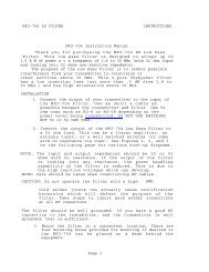
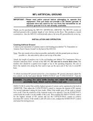
Connect the HF antenna jack on your transmitter or transceiver to the TX jack on the back of your<br />
Z-<strong>11Pro</strong> tuner using the coax jumper with standard PL-259 plugs. Attach your antenna lead-in<br />
coax to the Ant jack on the back of your Z-<strong>11Pro</strong> tuner.<br />
6
Your AT-100Pro can interface directly with many popular transceivers. For Icom radios, it will<br />
enable their “Tune” button to start a tuning cycle and provide power to the tuner.<br />
For Icom radios that are AH-3 or AH-4 compatible, connect the white molex connector into the<br />
radio’s tuner port. The power and radio plugs then connect to the tuner. The tuning process can<br />
start by either pressing the tune button on the tuner or the radio.<br />
For Yaesu FT-897 and 857, use the Y-ACC cable and plug the red end marked “Radio” into the<br />
radio’s ACC port. Connect the black end marked “<strong>Tuner</strong>” into the tuner’s interface jack. The radio<br />
does not supply power to the tuner. The tune button on the tuner is used for starting the tune<br />
process.<br />
If you are not using an interface cable to a radio capable of powering the tuner, connect your Z-<br />
<strong>11Pro</strong> to a source of DC power capable of providing 8 – 16 volts DC at 300 mA, using the<br />
provided 2.5x5.5mm coaxial cable (center positive). If your radio is powered by 12 VDC, you<br />
can use the same power supply for the Z-<strong>11Pro</strong>, providing the power supply can source the extra<br />
300 mA required by the tuner during a tuning cycle. Note that the Yaesu interface cable does not<br />
power the radio.<br />
Grounding your tuner will enhance its performance and safety. <strong>LDG</strong> recommends that you<br />
connect your tuner to a suitable ground; a dedicated ground rod connected to buried radials is<br />
preferred, but a single ground rod or a cold water pipe can provide a serviceable ground. <strong>LDG</strong><br />
strongly recommends that you use a properly installed, high quality lightning arrestor on all<br />
antenna cables.<br />
Z-<strong>11Pro</strong> <strong>Tuner</strong><br />
Ant<br />
TX<br />
To <strong>Antenna</strong><br />
<strong>LDG</strong><br />
<strong>Electronics</strong><br />
Ground<br />
Radio<br />
Power<br />
Interface<br />
Cable<br />
Ground Post<br />
<strong>Antenna</strong><br />
Transceiver<br />
Rear Panel<br />
(Typical)<br />
<strong>Tuner</strong><br />
P t<br />
DC Power<br />
Installing An Internal Battery<br />
Your Z-<strong>11Pro</strong> uses so little power it will run off many configurations of batteries, providing<br />
portable operation independent of AC power supplies. You can plug your Z-<strong>11Pro</strong> into an<br />
external battery pack, but even better, you can install a battery inside your Z-<strong>11Pro</strong>, making it<br />
self-powered! Adapting your Z-<strong>11Pro</strong> to battery power involves only a few minor modifications.<br />
7
Many battery options present themselves. Remember, your Z-<strong>11Pro</strong> will work well with as little<br />
as 8 volts. Let's assume that you'll make 20 tunes per day: 15 memory tunes and 5 full tunes.<br />
That amounts to 2 mAh per day 2 . Here are some estimates of battery life for various<br />
combinations of cells:<br />
Qty Type mAh Days Notes<br />
Three AA Lithium 2100 1050 (these are 3.6 volts each)<br />
Eight AAA NiMH 850 425<br />
Eight AAA Alkaline 1150 575<br />
Eight AA NiMH 2000 1000<br />
Eight AA Alkaline 2850 1425 (almost 4 years!)<br />
Note that these estimates do not account for self-discharge in NiMH batteries. Choose NiMH for<br />
more frequent or heavy use, Alkaline or Lithium for long shelf life. Lithium batteries are more<br />
expensive, but are quite a bit lighter than Alkalines of the same size, and you only need three 3.6<br />
volt Lithium cells instead of eight Alkalines. This makes them an attractive option for portable<br />
operation, adding minimal weight.<br />
Also note that while a single 9V battery is within the voltage specification, it does not produce<br />
enough current to properly power a Z-<strong>11Pro</strong>.<br />
Suitable battery holders are readily available. Radio Shack (www.radioshack.com) sells holders<br />
for 4 and 8 cells. Mouser (www.mouser.com) and Digikey (www.digikey.com) sell holders for 2,<br />
3, 4, 6 or 8 cells.<br />
To install a battery or battery pack inside, disconnect your Z-<strong>11Pro</strong>. Open the case by removing<br />
the four screws (two on each side) and carefully lifting the top clear. You'll find room inside for<br />
the battery or battery pack on top of the relays; use double-sided foam tape to attach it there.<br />
There are two terminals on the Printed Circuit board for battery power. They are round lands with<br />
holes, immediately behind the DC power jack. The one directly behind the jack is for the Positive<br />
lead from the battery connector or holder (usually Red), the one offset slightly toward the center<br />
of the circuit board is for the Negative lead (usually Black; see the detail inset in the photo<br />
below). Carefully solder the leads into place, taking care to avoid solder "bridges" to other parts<br />
of the PC board. If you are using AA or AAA batteries in a holder, put a length of tape over them<br />
to keep them securely in their holder.<br />
2 The tuner draws 250 mA average while tuning and virtually no current while idle. Memory tunes take 0.1<br />
seconds, full tunes 3 seconds on average. Your battery life will depend on how you operate, how often you<br />
tune, and whether you use full or memory tuning.<br />
8
Replace the cover, being careful not to pinch or short the wires. You can use your Z-<strong>11Pro</strong> on<br />
external power even when batteries are installed, but the external power supply will not charge<br />
the batteries. You will need to remove any rechargeable batteries from the Z-<strong>11Pro</strong> and charge<br />
them in an external charger when needed.<br />
Modern batteries aren't very likely to leak, but why take the chance If you won't be using your<br />
Z-<strong>11Pro</strong> for a month or more, remove all batteries and store them separately.<br />
9
Operation<br />
Overview and Setup<br />
All functions are controlled through the six front panel buttons. Functions are generally invoked<br />
when a button is released, although in some cases you will hold a button down for a short time.<br />
Some commands are indicated by the length of time you hold a button before releasing it. There<br />
are three lengths of press: short (less than 0.4 seconds), medium (0.5 – 2.9 seconds) and long<br />
(more than 3 seconds). This sounds a lot more complicated than it really is; this interface will<br />
quickly become familiar and easy. The LEDs provide timing cues:<br />
No LEDs lit: short press<br />
Outer LEDs lit: medium press<br />
Inner LEDs lit: long press<br />
Four special functions are invoked with the Func button; the second function of these four<br />
buttons is indicated below each on the front panel. For these functions, press and release the<br />
Func button; the LEDs will scroll to the right to indicate Func mode. Then, press and release a<br />
button to invoke its second function. If you don't press another button within 3 seconds, the LEDs<br />
will scroll back to the left, indicating that the tuner has exited Func mode. You also use the<br />
Func button to check the settings. Press and hold the Func button while pressing the second<br />
button; the status of that function will be displayed on the LEDs.<br />
Tuning Modes: Your Z-<strong>11Pro</strong> features two distinct tuning modes: Auto and Semi. In Auto mode,<br />
a tuning cycle will automatically begin whenever the SWR exceeds a threshold value; the default<br />
SWR threshold is 2.0, but you can set it to any SWR value between 1.5 and 3.0 (see below). In<br />
Semi mode a tuning cycle will begin only when you press and release the Tune button while<br />
transmitting, regardless of SWR. The default mode is Auto.<br />
To toggle between Auto and Semi modes, press and release the Func button then press and<br />
release the C Dn button. The two inner LEDs will flash to indicate Auto mode, the two outer<br />
LEDs to indicate Semi-Auto mode. To check the setting, press and hold the Func button, then<br />
press and release the C Dn button.<br />
Outer LEDs flash: Semi mode<br />
Inner LEDs flash: Auto mode<br />
Auto Tune Threshold: You can set the SWR threshold at which an automatic tuning cycle will<br />
begin. Press and release the Func button, then press and release the L Dn button. The first press<br />
of these buttons shows the current SWR threshold setting:<br />
Green = 1.5<br />
Green + Yellow = 1.7<br />
Yellow = 2.0<br />
Yellow + Red = 2.5<br />
Red = 3.0<br />
Repeat this button combination to cycle through the choices (lowest to highest, then wrap<br />
around). As soon as the selection is changed, the tuner is ready for operation.<br />
10
High/Low Impedance Toggle:<br />
You can manually set your Z-<strong>11Pro</strong> for Hi-Z or Lo-Z antennas. Press and release the Func<br />
button, then press and release the L Up button. Each such button sequence will toggle between<br />
High and Low. The Yellow LED indicates Low, the Red >3.0 LED High. Pressing L Up while<br />
holding Func will show the present setting. This function is rarely needed; it is available for the<br />
more advanced user to temporarily set the tuner to an L-C or C-L configuration. In any case, the<br />
setting is automatically configured the next time an Auto or Semi-Auto tuning cycle is run.<br />
Low Impedance<br />
High Impedance<br />
Firmware Version Readout<br />
You can read out the firmware version by pressing Func + C Up + L Up all at the same time.<br />
The green LED flashes the whole part of the number, the yellow LED flashes briefly to indicate<br />
the decimal point, then the red LED flashes the decimal part of the number. Example: Version 2.3<br />
would be indicated by Green-Green-Yellow-Red-Red-Red 3 .<br />
EEPROM Reset<br />
You can clear all tuning memories and tuner settings by pressing Func + C Dn + Tune. All<br />
LEDs light, then go off in sequence right to left. Use this command with caution, as it erases all<br />
tuning memories and settings, and restores factory defaults. Tin other words, there is no "Are you<br />
sure" step; Memory will be cleared as soon as you press these three buttons together.<br />
Tuning<br />
Auto and Semi modes<br />
In Auto mode (see section on selection Auto or Semi mode) the tuner will begin a tuning cycle<br />
whenever the SWR exceeds the value you set (see section on setting Auto Tune Threshold). In<br />
Semi mode, a tuning cycle begins only when you start one by pressing the Tune button,<br />
regardless of SWR. You can also start a Semi tuning cycle while the tuner is in Auto mode. Your<br />
personal operating practices will determine which mode is best for you. The default mode is Auto<br />
(see Application Notes for more on when to use Auto mode).<br />
Auto mode tuning works well while you are transmitting in SSB, AM, CW or any digital mode.<br />
Recent advances in <strong>LDG</strong>'s tuning algorithms allow your Z-<strong>11Pro</strong> to tune effectively even with a<br />
varying RF signal. This means that as you change frequencies, modes, antennas or bands, you<br />
don't have to make a separate tuning transmission; just start talking or keying and your Z-<strong>11Pro</strong><br />
will match up in as little as 0.1 seconds.<br />
Memories<br />
This is pretty amazing, so lash yourself to the mast: your Z-<strong>11Pro</strong> has 8,000 3-D frequency<br />
memories. These are "Continuous Q Matched" memories from 1.8 MHz to 54 MHz; there are<br />
more memories on lower frequencies where antenna Q is usually higher, and fewer memories on<br />
higher frequencies); there are four memories per frequency They store the tuning parameters for<br />
each frequency as you tune; that's 2,000 memories for each of four different antennas. You can<br />
use a wide variety of antennas, connecting them as needed. Just think of it; you could be using a<br />
Yagi, Quad, Loop, and Dipole and each of them will have 2,000 dedicated memories. When you<br />
transmit on or near a memorized frequency again, the tuner finds the best match for that antenna<br />
3 This is only an example; your tuner may have a different firmware version.<br />
11
and sets those parameters in a fraction of a second, much faster than a full tuning cycle. 3-D<br />
memory is an exclusive <strong>LDG</strong> technology, available only in <strong>LDG</strong> tuners.<br />
When you tune using Semi mode, you can select between a Memory tune and a Full tune. If you<br />
select Memory tune and there is no appropriate memory data, the tuner will automatically begin a<br />
full tuning cycle. Tuning parameters are stored in EEPROM memory, and are retained<br />
indefinitely, even if power is removed. In Auto mode, Memory tune is used.<br />
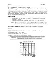
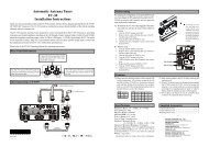
Using your Z-<strong>11Pro</strong> with the DTS-4 Intelligent <strong>Antenna</strong> Switch<br />
3-D memories make switching among various antennas a breeze. Using <strong>LDG</strong>'s DTS-4 Intelligent<br />
Desktop <strong>Antenna</strong> Switch, you can instantly connect up to four separate antennas with the press of<br />
a button. Your Z-<strong>11Pro</strong> will search it's 3-D memory bank for stored settings for each antenna and<br />
for the present frequency, and reset to them in less than 0.1 seconds. Working together, your Z-<br />
<strong>11Pro</strong> and DTS-4 Intelligent <strong>Antenna</strong> Switch makes switching and matching up to four antennas<br />
automatic and virtually instantaneous.<br />
The small size of the DTS-4R remote control for the DTS-4 Intelligent <strong>Antenna</strong> Switch makes it<br />
especially appropriate for use with the compact Z-<strong>11Pro</strong>. The information on the next page shows<br />
how these two groundbreaking <strong>LDG</strong> products can be used together.<br />
Yagi<br />
You can connect up to four antennas to the DTS-4 Intelligent<br />
<strong>Antenna</strong> Switch, and then connect to your transceiver via the<br />
Z-<strong>11Pro</strong> tuner. Instant switching, automatic safety<br />
grounding, and 3-D memory tuning make changing antennas<br />
nearly instantaneous.<br />
Quad<br />
DTS-4<br />
Intelligent<br />
Switch<br />
Z-<strong>11Pro</strong><br />
<strong>Tuner</strong><br />
Transceiver<br />
The Z-<strong>11Pro</strong> with the DTS-4R remote control, connected to<br />
the DTS-4 Intelligent <strong>Antenna</strong> Switch, ready to rock and<br />
roll. You can instantly switch between any of four antennas,<br />
and the Z-<strong>11Pro</strong> will recall separate saved tuner settings for<br />
each antenna in less than 0.1 seconds.<br />
Dipole<br />
Vertical<br />
12
Full tuning cycle (long press)<br />
Set your transmitter or transceiver to SSB, AM, FM, CW or Packet mode, and a power level of no<br />
more than 125 watts if your radio has a power rollback circuit. If your radio lacks a rollback<br />
circuit (see your owner’s manual), set the power level to no more than 25 watts.<br />
Press the PTT switch on the microphone (close key on CW) to transmit a carrier, or simply begin<br />
talking on SSB or AM. While transmitting, press and hold the Tune button on the front of your<br />
Z-<strong>11Pro</strong> for at least 3 seconds (two inner LEDs lit).<br />
Release the Tune button; a Semi-Auto tuning cycle will begin. The Tune LED will light and you<br />
will hear the relays in your Z-<strong>11Pro</strong> as they switch in and out seeking a match; they make a pretty<br />
loud buzzing noise. The tuning cycle will end in a few seconds with the LEDs indicating the final<br />
match. At the end of a full tuning cycle, the LEDs will scan inward from both ends to indicate a<br />
successful tune to an SWR of less than 1.5 4 , and will then indicate the final achieved SWR.<br />
Unkey your transmitter or transceiver and reset to your desired power if you changed for tuning −<br />
you’re ready to operate. The new tuning parameters are stored for the present operating<br />
frequency, replacing the oldest of the five parameters that were previously stored for that<br />
frequency, if any.<br />
If you try to run a full tuning cycle when the SWR is already below the Auto tune threshold, the<br />
LEDs will blink twice to indicate you already have a match, and no tuning cycle will begin. If<br />
insufficient RF is present, all LEDs blink three times, and no tuning cycle will begin.<br />
Memory tuning cycle (medium press)<br />
If you are tuning near a frequency at which you have already completed a tuning cycle, you can<br />
reset the tuner very quickly by using a Memory Tuning Cycle. Key your transmitter as described<br />
above, and press and hold the Tune button for .5 to 2.9 seconds (two outer LEDs lit), then release.<br />
The tuner will automatically check for a saved tuning setting, and if present, will restore that<br />
setting in less than 0.1 seconds. If no tuned setting is saved near the present frequency, the tuner<br />
will begin a full tuning cycle, saving the result when finished for future operation on that<br />
frequency. In this way, your Z-<strong>11Pro</strong> “learns”; the longer you use it, the more closely it adapts<br />
itself to the bands and frequencies you use. If insufficient RF is present, all LEDs blink three<br />
times, and no tuning cycle will begin. You will probably use Memory Tuning most of the time; it<br />
takes advantage of any stored tuning settings, but automatically defaults to a Full Tuning cycle if<br />
no stored data is available<br />
Bypass/Recall mode (short press)<br />
To place your Z-<strong>11Pro</strong> in bypass mode, press the Tune button less than a half-second. The tuner<br />
will switch to bypass, and all LEDs will flash three times to confirm bypass mode. In bypass<br />
mode, RF from your transmitter goes directly to the antenna with no matching. A second short<br />
press recalls the last tuned setting; all LEDs flash once. Repeated button presses will toggle<br />
between bypass and recall; repeat as necessary. Bypass followed by Func then Tune will clear<br />
the present memory. Bypass mode is not saved when you power down. On the next power up, the<br />
tuner will reset the last tuned settings. You can, if you wish, press Func then Tune to save the<br />
bypass setting, erasing the oldest of the four memories for the present frequency.<br />
4 <strong>LDG</strong>'s chief engineer, a fan of Snoopy in the Peanuts comic strip, calls this the "Happy Dance".<br />
13
SWR indication<br />
During a tuning cycle, the LEDs indicate the present SWR. It will vary considerably as the Z-<br />
<strong>11Pro</strong> seeks a match. You have to watch closely though, as it happens fast!<br />
"Sleep" mode<br />
When any tuning cycle ends, the tuner automatically enters a “deep sleep” state in which it draws<br />
only 25 microamps. The tuner will automatically “wake up” the next time you start a tuning<br />
cycle, a button is pressed or when an automatic tuning cycle is required, if this option is selected.<br />
Advanced Operation<br />
Manual adjustments<br />
In rare cases, it may be desirable to manually adjust the match after a tuning cycle. This will<br />
happen most often with antennas that are far from resonance at the operating frequency. The C<br />
Up, C Dn, L Up and L Dn buttons increase and decrease capacitance and inductance,<br />
respectively. To change these values, press repeatedly or hold any of these buttons. Then, key<br />
your transmitter to observe the achieved SWR on the SWR meter.<br />
You can also manually change C and L as you transmit, observing the SWR on the LEDs. When<br />
you reach the limits of these adjustments, the LEDs blink: the inner LEDs indicate the high limit,<br />
outer LEDs low.<br />
Frankly, you won't use these manual adjustments much. Your Z-<strong>11Pro</strong> is very, very good at<br />
finding a match. These functions are included only to provide you with the maximum utility and<br />
flexibility.<br />
After manually adjusting the match, you can store the tuning parameters for the present<br />
frequency; press and release Func, then press and release Tune. The parameters are stored for<br />
later recall, replacing any the oldest of four saved parameters for that frequency.<br />
14
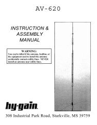
Function Button Strokes LED Indications<br />
Toggle<br />
Auto / Semi<br />
Modes<br />
Auto Tune<br />
Threshold<br />
Hi-Lo Z<br />
Select<br />
Full Tune<br />
Cycle<br />
Memory Tuning<br />
Cycle<br />
Bypass/Restore<br />
Firmware Version<br />
Readout<br />
Func then C Dn<br />
Func then L Dn<br />
Func then L Up<br />
Tune (long press)<br />
Tune (Medium press)<br />
Tune (Short press)<br />
Func + C Up + L Up<br />
(Together)<br />
Example: 2.3<br />
Auto<br />
Semi<br />
All LEDs Flash<br />
Bypass: 3 flashes<br />
Restore: 1 flash<br />
Memory Reset<br />
Func + C Dn + Tune<br />
(Together)<br />
Z-<strong>11Pro</strong> Command Reference<br />
15
Application Notes<br />
Mobile Operation<br />
Your Z-<strong>11Pro</strong> is perfectly suited to mobile operation. You can install it under the dash along with<br />
your transceiver, or remotely in the trunk. The only requirements are that the tuner remain dry,<br />
and that you provide a fused source of DC power in accordance with the specifications. The Z-<br />
<strong>11Pro</strong> does not include an internal fuse; you must provide one in the DC line. <strong>LDG</strong> recommends<br />
a 2 Amp "fast blow" fuse. Make sure the tuner is well grounded to the car body.<br />
To install the unit under the dash, you can "homebrew" a bracket (<strong>LDG</strong> does not provide one).<br />
You can also use Velcro tape, although the adhesive tends to soften in hot weather. In the trunk,<br />
Velcro works well to secure the unit to the trunk floor. Simply run coax from your transceiver to<br />
the tuner, run a fused DC line to the tuner and connect your mobile antenna. Set the tuner to<br />
<strong>Automatic</strong> mode, and you're ready to go. The tuner will adjust the match as needed whenever you<br />
transmit on a new band or frequency. You can observe the progress of the match on your rig's<br />
SWR meter or on the Z-<strong>11Pro</strong>'s LEDs (not while driving; keep your eyes on the road!). When the<br />
reading stops changing, the tuner has finished tuning. Most of the time this will happen very<br />
quickly as the Z-<strong>11Pro</strong> tunes from memory in a fraction of a second.<br />
<strong>Tuner</strong><br />
2A<br />
Xcvr<br />
DC<br />
When To Use Auto Mode<br />
Auto mode is most useful when you are often changing frequencies and bands (a contest, for<br />
instance). With memory operation, Auto mode will retune almost instantly whenever you transmit<br />
on a new frequency. On the other hand, if your antenna SWR is relatively flat across the band of<br />
frequencies you're using, retuning might not be necessary, and semi-automatic mode would be<br />
preferable.<br />
MARS/CAP Coverage<br />
Your Z-<strong>11Pro</strong> provides continuous tuning over its specified range, not just in the ham bands. This<br />
makes it useful for MARS or CAP operation, or any other legal HF operation.<br />
16
Theory Of Operation<br />
Some Basic Ideas About Impedance<br />
The theory underlying antennas and transmission lines is fairly complex, and in fact employs a<br />
mathematical notation called “complex numbers” that have “real” and “imaginary” parts. It is<br />
beyond the scope of this manual to present a tutorial on this subject 5 , but a little background will<br />
help you understand what your Z-<strong>11Pro</strong> is doing, and how it does it.<br />
In simple DC circuits, the wire resists the current flow, converting some of it into heat. The<br />
relationship between voltage, current and resistance is described by the elegant and well-known<br />
“Ohm’s Law”, named for Georg Simon Ohm of Germany, who first discovered it in 1826. In RF<br />
circuits, an analogous but far more complicated relationship exists.<br />
RF circuits also resist the flow of electricity. However, the presence of capacitive and inductive<br />
elements causes the voltage in the circuit to lead or lag the current, respectively. In RF circuits<br />
this resistance to the flow of electricity is called “impedance”, and can include all three elements:<br />
resistive, capacitive, and inductive.<br />
Capacitive<br />
Reactance<br />
Inductive<br />
Reactance<br />
The output circuit of your transmitter consists of inductors and capacitors, usually in a<br />
series/parallel configuration called a “pi network”. The transmission line can be thought of as a<br />
long string of capacitors and inductors in series/parallel, and the antenna is a kind of resonant<br />
circuit. At any given RF frequency, each of these can exhibit resistance and impedance in the<br />
form of capacitive or inductive “reactance”.<br />
Transmitters, Transmission Lines, <strong>Antenna</strong>s and Impedance<br />
The output circuit of your transmitter, the transmission line, and the antenna all have a<br />
characteristic impedance. For reasons too complicated to go into here, the standard impedance is<br />
about 50 ohms resistive, with zero capacitive and inductive components. When all three parts of<br />
the system have the same impedance, the system is said to be “matched”, and maximum transfer<br />
of power from the transmitter to the antenna occurs. While the transmitter output circuit and<br />
transmission line are of fixed, carefully designed impedance, the antenna presents a 50 ohm, nonreactive<br />
load only at its natural resonant frequencies. At other frequencies, it will exhibit<br />
capacitive or inductive reactance, causing it to have an impedance other than 50 ohms.<br />
When the impedance of the antenna is different from that of the transmitter and transmission line,<br />
a “mismatch” is said to exist. In this case, some of the RF energy from the transmitter is reflected<br />
from the antenna back down the transmission line, and into the transmitter. If this reflected<br />
energy is strong enough it can damage the transmitter’s output circuits.<br />
The ratio of transmitted to reflected energy is called the “standing wave ratio”, or SWR. An SWR<br />
of 1 (sometimes written 1:1) indicates a perfect match. As more energy is reflected, the SWR<br />
5 For a very complete explanation of this subject, see any edition of the ARRL Handbook for Radio<br />
Communications (previously the Handbook For Radio Amateurs).<br />
17
ises to 2, 3 or higher. As a general rule, modern solid state transmitters must operate with an<br />
SWR of 2 or less. Tube exciters are somewhat more tolerant of high SWR. If your 50 ohm<br />
antenna is resonant at your operating frequency, it will show an SWR close to 1. However, this is<br />
usually not the case; operators often need to transmit at frequencies other than resonance,<br />
resulting in a reactive antenna and a higher SWR.<br />
1+<br />
R / F<br />
SWR = where F = Forward power (watts), R = Reflected power (watts)<br />
1−<br />
R / F<br />
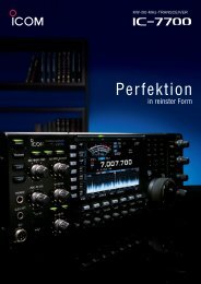
SWR is measured using a device called an “SWR bridge”, inserted in the transmission line<br />
between the transmitter and antenna. This circuit measures forward and reverse power from<br />
which SWR may be calculated (some meters calculate SWR for you). More advanced units can<br />
measure forward and reverse power simultaneously, and show these values and SWR at the same<br />
time.<br />
An antenna tuner is a device used to cancel out the effects of antenna reactance. <strong>Tuner</strong>s add<br />
capacitance to cancel out inductive reactance in the antenna, and vice versa. Simple tuners use<br />
variable capacitors and inductors; the operator adjusts them by hand while observing reflected<br />
power on the SWR meter until a minimum SWR is reached. Your <strong>LDG</strong> Z-<strong>11Pro</strong> automates this<br />
process.<br />
No tuner will fix a bad antenna. If your antenna is far from resonance, the inefficiencies inherent<br />
in such operation are inescapable; it’s simple physics. Much of your transmitted power may be<br />
dissipated in the tuner as heat, never reaching the antenna at all. A tuner simply “fools” your<br />
transmitter into behaving as though the antenna were resonant, avoiding any damage that might<br />
otherwise be caused by high reflected power. Your antenna should always be as close to<br />
resonance as practical.<br />
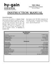
Reflected Power (Watts)<br />
Forward Power (Watts)<br />
20 30 40 50 60 70 80 90 100<br />
2 1.92 1.70 1.58 1.50 1.45 1.41 1.38 1.35 1.33<br />
4 2.62 2.15 1.92 1.79 1.70 1.63 1.58 1.53 1.50<br />
6 3.42 2.62 2.26 2.06 1.92 1.83 1.75 1.70 1.65<br />
8 4.44 3.14 2.62 2.33 2.15 2.02 1.92 1.85 1.79<br />
10 5.83 3.73 3.00 2.62 2.38 2.22 2.09 2.00 1.92<br />
12 7.87 4.44 3.42 2.92 2.62 2.41 2.26 2.15 2.06<br />
14 11.24 5.31 3.90 3.25 2.87 2.62 2.44 2.30 2.20<br />
16 17.94 6.42 4.44 3.60 3.14 2.83 2.62 2.46 2.33<br />
18 37.97 7.87 5.08 4.00 3.42 3.06 2.80 2.62 2.47<br />
20 - 9.90 5.83 4.44 3.73 3.30 3.00 2.78 2.62<br />
22 - 12.92 6.74 4.94 4.07 3.55 3.21 2.96 2.77<br />
24 - 17.94 7.87 5.51 4.44 3.83 3.42 3.14 2.92<br />
26 - 27.96 9.32 6.17 4.85 4.12 3.65 3.32 3.08<br />
28 - 57.98 11.24 6.95 5.31 4.44 3.90 3.52 3.25<br />
30 - - 13.93 7.87 5.83 4.79 4.16 3.73 3.42<br />
32 - - 17.94 9.00 6.42 5.18 4.44 3.95 3.60<br />
34 - - 24.63 10.40 7.09 5.60 4.75 4.19 3.80<br />
36 - - 37.97 12.20 7.87 6.07 5.08 4.44 4.00<br />
38 - - 77.99 14.60 8.80 6.60 5.44 4.71 4.21<br />
40 - - - 17.94 9.90 7.19 5.83 5.00 4.44<br />
42 - - - 22.96 11.24 7.87 6.26 5.31 4.68<br />
44 - - - 31.30 12.92 8.65 6.74 5.65 4.94<br />
46 - - - 47.98 15.08 9.56 7.27 6.02 5.22<br />
48 - - - 97.99 17.94 10.63 7.87 6.42 5.51<br />
50 - - - - 21.95 11.92 8.55 6.85 5.83<br />
SWR Lookup Table<br />
Find SWR at intersection of<br />
forward power column and<br />
reflected power row.<br />
18
The <strong>LDG</strong> Z-<strong>11Pro</strong><br />
In 1995 <strong>LDG</strong> pioneered a new type of automatic antenna tuner. The <strong>LDG</strong> design uses banks of<br />
fixed capacitors and inductors, switched in and out of the circuit by relays under microprocessor<br />
control. A built-in SWR sensor provides feedback while the microprocessor searches the<br />
capacitor and inductor banks, seeking the lowest possible SWR. The tuner is a “Switched L”<br />
network consisting of series inductors and parallel capacitors. <strong>LDG</strong> chose the L network for it’s<br />
minimum number of parts and its ability to tune unbalanced loads, such as coax-fed dipoles,<br />
verticals, Yagis or virtually any coax-fed antenna. The inductors are switched in and out of the<br />
circuit by relays controlled by the microprocessor. An additional relay switches between high and<br />
low impedance ranges.<br />
The capacitors are connected to ground with the inductor relays. Another relay switches the entire<br />
capacitor bank to the input or output side of the inductor. This switching allows the Z-<strong>11Pro</strong> to<br />
automatically handle loads that are greater than 50 ohms (high setting) and less than 50 (low<br />
setting).<br />
The SWR sensor is a variation of the Bruene circuit. This SWR measuring technique is used in<br />
most dual-meter and direct-reading SWR meters. Slight modifications were made to the circuit to<br />
provide voltages (instead of currents) for the analog-to-digital converters (ADCs) that provide<br />
signals proportional to the forward and reverse power levels. The single-lead primary through the<br />
center of the sensor transformer provides RF current sampling. Diodes rectify the sample and<br />
provide a DC voltage proportional to RF power. Variable resistors calibrate the FORWARD and<br />
REVERSE power levels. Once adjusted, the forward and reverse power sensors produce a<br />
calibrated DC voltage proportional to the forward and reverse RF power levels. These two<br />
voltages are read by the ADCs in the microprocessor. Once in a digital format, they are used to<br />
calculate SWR in real time.<br />
The relays operate from DC supplied by the power input jack. The total current drawn by the Z-<br />
<strong>11Pro</strong> depends primarily on the number of energized relays, with the maximum current drain<br />
being approximately 300 mA, but only during the few seconds a tuning cycle is running. At all<br />
other times, the tuner is in a “deep sleep” mode drawing only a few milliamps. The last tuned<br />
setting is automatically reset on the next power-up.<br />
The microprocessor’s oscillator runs at 20 MHz. The main tuning routine takes about 75 cycles to<br />
make a tuner adjustment and take a new SWR measurement, or 7 milliseconds per tuner<br />
adjustment. If running at maximum speed, the microprocessor can try all inductor-capacitor<br />
combinations in under 3 seconds. Unfortunately, the mechanical relays can’t react as quickly as<br />
the microprocessor, and the tuning speed must be slowed down to compensate for relay settling<br />
time.<br />
The tuning routine includes an algorithm to minimize the number of tuner adjustments. The<br />
routine first de-energizes the high/low impedance relay if necessary, then individually steps<br />
through the inductors to find a coarse match. With the best inductor selected, the tuner then steps<br />
through the individual capacitors to find the best coarse match. If no match is found, the routine<br />
repeats the coarse tuning with the high/low impedance relay energized. The routine then fine<br />
tunes the capacitors and inductors. The program checks LC combination to see if a 1.5 or lower<br />
SWR can be obtained, and stops when it finds a good match.<br />
The microprocessor runs a fine tune routine just after the tuner finds a match at an SWR of 1.5 or<br />
less. This routine tries to get the SWR as low as possible (not just 1.5); it takes about a half<br />
19
second to run. There is also a quick tune mode. If the SWR is below 2.0 when you press the tune<br />
button to start a tuning cycle, the tuner will first try a memory tune routine to see if it can achieve<br />
a low SWR without a complete re-tune. This also takes about a half second to run. If it does not<br />
find a good match, then it runs a full tuning routine.<br />
A Word About Tuning Etiquette<br />
Be sure to use a vacant frequency to tune. With today’s crowded ham bands, this is often difficult.<br />
However, do your best to avoid interfering with other hams as you tune. Your Z-<strong>11Pro</strong>’s very<br />
short tuning cycle, often only a fraction of a second, minimizes the impact of your tuning<br />
transmissions. Tune at reduced power whenever possible; one or two watts is plenty.<br />
Care and Maintenance<br />
Your Z-<strong>11Pro</strong> tuner is essentially maintenance-free; just be sure to observe the power limits<br />
discussed in this manual. The outer case may be cleaned as needed with a soft cloth slightly<br />
dampened in household cleaning solution. As with any modern electronic device, your Z-<strong>11Pro</strong><br />
can be damaged by temperature extremes, water, impact or static discharge. <strong>LDG</strong> strongly<br />
recommends that you use a good quality, properly installed lightning arrestor in the antenna lead.<br />
Technical Support<br />
We are happy to help you with your product. For detailed tech support, submit our Tech Support<br />
form on our web site under Support/Manuals, then Tech Support. You can find us at<br />
www.ldgelectronics.com.<br />
Warranty and Service<br />
Your product is warranted against defects in parts or workmanship for two years from purchase.<br />
The warranty does not cover damage due to abuse or exceeding specifications. This warranty<br />
applies to the original purchaser only; it is not transferable. A copy of the receipt showing the<br />
purchaser’s name and the date of purchase must accompany units returned for warranty service.<br />
All returns must be shipped to us pre-paid; we will not accept units with postage due. Please fill<br />
out and print the return form from our web site under Support/Manual, then Tech Support-<br />
Warranty.<br />
If you need to return your unit to us for service, package it carefully, keeping in mind that we will<br />
re-use your packaging to return the unit to you. Include a full description of the problem, along<br />
with your name, address and a phone number or e-mail address on the web form. Repairs average<br />
about 3 to 6 weeks.<br />
We will be glad to service your unit after the warranty period has ended. We will notify you of<br />
repair charges by phone or e-mail, and bill you after repairs are completed.<br />
Firmware Upgrades<br />
From time to time <strong>LDG</strong> may release upgraded firmware for the Z-<strong>11Pro</strong>, refining operation and<br />
adding features. Your Z-<strong>11Pro</strong> is not field programmable. You will have to remove the present<br />
chip and replace it with the upgrade chip. Upgrades are expected to cost about $10-$20, and will<br />
be announced on our web site when available.<br />
20