FT-857D OM - Yaesu UK Ltd
FT-857D OM - Yaesu UK Ltd
FT-857D OM - Yaesu UK Ltd
- No tags were found...

You also want an ePaper? Increase the reach of your titles
YUMPU automatically turns print PDFs into web optimized ePapers that Google loves.
SPECIFICATIONSGeneralFrequency Range:Emission Modes:Receive: 0.1-56 MHz, 76-108 MHz, 118-164 MHz,420-470 MHzTransmit: 160 - 6 Meters (USA: includes 60 meters),2 Meters,70 Centimeters (Amateur bands only)A1 (CW), A3 (AM), A3J (LSB/USB), F3 (FM),F1 (9600 bps packet), F2 (1200 bps packet)10 Hz (CW/SSB), 100 Hz (AM/FM/WFM)50 Ohms, Unbalanced14 ºF to 140 ºF (–10 °C to +60 °C)Synthesizer Steps (Min.):Antenna Impedance:Operating Temp. Range:Frequency Stability: ±4 ppm from 1 min. to 60 min after power on.@25 °C: 1 ppm/hour±0.5 ppm/1 hour @25 °C, after warmup(with optional TCXO-9)Supply Voltage:Current Consumption:Case Size (W x H x D):Weight (Approx.):Normal: 13.8 VDC ±15 %, Negative GroundSquelched: 550 mA (Approx.)Receive: 1 ATransmit: 22 A6.1” x 2.0” x 9.2” (155 x 52 x 233 mm)4.6 lb. (2.1 kg)TransmitterRF Power Output: SSB/CW/FM AM Carrier(@13.8 V DC) 160- 6 M: 100 W 25 W2 M: 50 W 12.5 W70 CM: 20 W 5 WModulation Types: SSB: Balanced Modulator,AM: Early Stage (Low Level),FM: Variable ReactanceFM Maximum Deviation: ±5 kHz (FM-N: ±2.5 kHz)Spurious Radiation: –50 dB (1.8-29.7 MHz)–60 dB (50/144/430 MHz)Carrier Suppression: >40 dBOpp. Sideband Suppression: >50 dBSSB Frequency Response: 400 Hz-2600 Hz (–6 dB)Microphone Impedance: 200-10k Ohms (Nominal: 600 Ohms)2 <strong>FT</strong>-<strong>857D</strong> Operating Manual
SPECIFICATIONSReceiverCircuit Type:Double-Conversion Superheterodyne (SSB/CW/AM/FM)Superheterodyne (WFM)Intermediate Frequencies: 1st: 68.33 MHz (SSB/CW/AM/FM); 10.7 MHz (WFM)2nd: 455 kHzSensitivity: SSB/CW AM FM100 kHz-1.8 MHz – 32 µV –1.8 MHz-28 MHz 0.2 µV 2 µV –28 MHz-30 MHz 0.2 µV 2 µV 0.5 µV50 MHz-54 MHz 0.125 µV 1 µV 0.2 µV144/430 MHz 0.125 µV – 0.2 µV(SSB/CW/AM = 10 dB S/N, FM = 12 dB SINAD)Squelch Sensitivity: SSB/CW/AM FM100 kHz-1.8 MHz – –1.8 MHz-28 MHz 2.5 µV –28 MHz-30 MHz 2.5 µV 0.32 µV50 MHz-54 MHz 1 µV 0.16 µV144/430 MHz 0.5 µV 0.16 µVImage Rejection:HF/50 MHz: 70 dB,144/430 MHz: 60 dBIF Rejection:60 dBSelectivity (–6/–60 dB): SSB/CW: 2.2 kHz/4.5 kHzAM: 6 kHz/20 kHzFM: 15 kHz/30 kHzFM-N: 9 kHz/25 kHzSSB (optional YF-122S installed): 2.3 kHz/4.7 kHz (–66 dB)CW (option YF-122C installed): 500 Hz/2.0 kHzCW (option YF-122CN installed): 300 Hz/1.0 kHzAF Output:2.5 W (@4 Ohms, 10% THD or less)AF Output Impedance: 4-16 OhmsSpecifications are subject to change without notice, and are guaranteed within the amateurbands only.<strong>FT</strong>-<strong>857D</strong> Operating Manual3
ACCESSORIES & OPTIONSSUPPLIED ACCESSORIESHand Microphone MH-31A8J ............................................................................................. 1Mobile Mounting Bracket MMB-82 .................................................................................. 1Control Cable...................................................................................................................... 1DC Power Cord .................................................................................................................. 1Operating Manual ............................................................................................................... 1Warranty Card ..................................................................................................................... 1FP-1030AYF-122SYF-122CYF-122CNTCXO-9MD-200A8XMH-36E8JMH-59A8JYSK-857FC-30ATAS-100ATAS-120ATAS-25ATBK-100VL-1000CT-62CT-39ACT-58AVAILABLE OPTIONSExternal AC Power Supply (25A)Collins SSB Filter (2.3 kHz/4.7 kHz: –6 dB/–66 dB)Collins CW Filter (500 Hz/2 kHz: –6 dB/–60 dB)Collins CW Filter (300 Hz/1 kHz: –6 dB/–60 dB)TCXO Unit (±0.5 ppm)Desktop MicrophoneDTMF MicrophoneRemote Control MicrophoneSeparation KitExternal Automatic Antenna TunerActive-Tuning Antenna SystemActive-Tuning Antenna SystemActive-Tuning Antenna SystemVHF/UHF Antenna Base/Counterpoise KitSolid-State Linear AmplifierCAT Interface CablePacket CableBAND DATA Cable4 <strong>FT</strong>-<strong>857D</strong> Operating Manual
INSTALLATIONThis chapter describes the installation procedure for integrating the <strong>FT</strong>-<strong>857D</strong> into a typicalamateur radio station. It is presumed that you possess technical knowledge and conceptualunderstanding consistent with your status as a licensed radio amateur. Please take someextra time to make certain that the important safety and technical requirements detailed inthis chapter are followed closely.PRELIMINARY INSPECTIONInspect the transceiver visually immediately upon opening the packing carton. Confirm thatall controls and switches work freely, and inspect the cabinet for any damage. Gently shakethe transceiver to verify that no internal components have been shaken loose due to roughhandling during shipping.If any evidence of damage is discovered, document it thoroughly and contact the shippingcompany (or your local dealer, if the unit was purchased over-the-counter) so as to getinstructions regarding the prompt resolution of the damage situation. Be certain to save theshipping carton, especially if there are any punctures or other evidence of damage incurredduring shipping; if it is necessary to return the unit for service or replacement, use the originalpacking materials but put the entire package inside another packing carton, so as topreserve the evidence of shipping damage for insurance purposes.INSTALLATION TIPSTo ensure long life of the components, be certain to provide adequate ventilation around thecabinet of the <strong>FT</strong>-<strong>857D</strong>.Do not install the transceiver on top of another heat-generating device (such as a powersupply or amplifier), and do not place equipment, books, or papers on top of the <strong>FT</strong>-<strong>857D</strong>.Avoid heating vents and window locations that could expose the transceiver to excessivedirect sunlight, especially in hot climates. The <strong>FT</strong>-<strong>857D</strong> should not be used in an environmentwhere the ambient temperature exceeds 140º F (+60 °C).<strong>FT</strong>-<strong>857D</strong> Operating Manual5
INSTALLATIONSAFETY INFORMATIONThe <strong>FT</strong>-<strong>857D</strong> is an electrical apparatus, as well as a generator of RF (Radio Frequency)energy, and you should exercise all safety precautions as are appropriate for this type ofdevice. These safety tips apply to any device installed in a well-designed amateur radiostation.Never allow unsupervised children to play in the vicinity of your transceiver or antennainstallation.Be certain to wrap any wire or cable splices thoroughly with insulating electricaltape, to prevent short circuits.Do not route cables or wires through door jambs or other locations where, throughwear and tear, they may become frayed and shorted to ground or to each other.Do not stand in front of a directional antenna while you are transmitting into thatantenna. Do not install a directional antenna in any location where humans or petsmay be walking in the main directional lobe of the antenna’s radiation pattern.In mobile installations, it is preferable to mount your antenna on top of the roof of thevehicle, if feasible, so as to utilize the car body as a counterpoise for the antenna andraise the radiation pattern as far away from passengers as possible.During vehicular operation when stopped (in a parking lot, for example), make it apractice to switch to Low power if there are people walking nearby.Never wear dual-earmuff headphones while driving a vehicle.Do not attempt to drive your vehicle while making a telephone call on an autopatchusing the DTMF microphone. Pull over to the side of the road, whether dialing manually.6 <strong>FT</strong>-<strong>857D</strong> Operating Manual
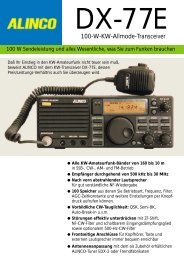
POWERONOFF0 5 10 15 20 0 5 20 30 40VCONTINUOUS CURRENT 25AAOVERLOADINSTALLATIONPOWER CONNECTIONSThe DC power connector for the <strong>FT</strong>-<strong>857D</strong> must only be connected to a DC source providing13.8 Volts DC (±15%), and capable of at least 22 Amperes of current. Always observeproper polarity when making DC connections:The Red DC power lead connects to the Positive (+) DC terminal; and the Black DC powerlead connects to the Negative (–) DC terminal.In mobile installations, noise pickup may be minimized by connecting the DC cable directlyto your vehicle’s battery, rather than to the ignition switch or “accessory” circuitry. Directconnection to the battery also provides the best voltage stability.To HF/50 MHz AntennaTo 144 MHz/430 MHz AntennaCigarette Lighter PlugFuse Box12V BatteryFUSE: 25AREDBLACKTo HF/50 MHz AntennaTo 144 MHz/430 MHz AntennaSupplied DC CableFP-1030AFUSE: 25AREDBLACKSupplied DC Cable8 <strong>FT</strong>-<strong>857D</strong> Operating Manual
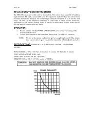
GROUNDINGINSTALLATIONBase Station Earth GroundingTypically, the ground connection consists of one or more copper-clad steel rods, driven intothe ground. If multiple ground rods are used, they should be configured in a “V” configuration,and bonded together at the apex of the “V” which is nearest the station location. Use aheavy, braided cable (such as the discarded shield from type RG-213 coaxial cable) andstrong cable clamps to secure the braided cables to the ground rods. Be sure to weatherproofthe connections to ensure many years of reliable service. Use the same type of heavy, braidedcable for the connections to the station ground bus (described below).Do not use gas line pipes in an attempt to provide a ground connection! To do so creates aserious risk of explosion!!Inside the station, a common ground bus consisting of a copper pipe of at least 1” (25 mm)diameter should be used. An alternative station ground bus may consist of a wide copperplate (single-sided circuit board material is ideal) secured to the bottom of the operatingdesk. Grounding connections from individual devices such as transceivers, power supplies,and data communications devices should be made directly to the ground bus using a heavy,braided cable.Do not make ground connections from one electrical device to another, and thence to theground bus. This so-called “Daisy Chain” grounding technique may nullify any attempt ateffective radio frequency grounding. See the drawings below for examples of proper andimproper ground connections.Improper Ground ConnectionProper Ground ConnectionTransceiverLinearAmplifierPowerSupplyTransceiverLinearAmplifierPowerSupply"Daisy Chain"<strong>FT</strong>-<strong>857D</strong> Operating Manual11
INSTALLATIONANTENNA CONSIDERATIONSThe antenna systems connected to your <strong>FT</strong>-<strong>857D</strong> transceiver are, of course, critically importantin ensuring successful communications. The <strong>FT</strong>-<strong>857D</strong> is designed for use with anyantenna system providing a 50 Ω resistive impedance at the desired operating frequency.While minor excursions from the 50 Ω specification are of no consequence, the poweramplifier’s protection circuitry will begin to reduce the power output of there is more than a50% divergence from the specified impedance (less than 33 Ω or greater than 75 Ω, correspondingto a Standing Wave Ratio (SWR) of 1.5:1).Two antenna jacks are provided on the rear panel of the <strong>FT</strong>-<strong>857D</strong>. The “HF/50 MHz ANT”jack is used for HF and 50 MHz, while the “144/430 MHz ANT” jack is used for 144 MHzand 430 MHz.Guidelines for successful base and mobile station installations are shown below.Mobile Antenna InstallationsMobile antennas for the HF bands, with the possible exception of those designed for 28MHz, display very high “Q” due to the fact that they must be physically shortened, thenresonated using a loading coil. Additional system bandwidth may be realized using the <strong>Yaesu</strong>FC-30 Automatic Antenna Tuner, which will present a 50 Ω impedance to your transceiveron the 1.8 ~ 50 MHz bands so long as the SWR on the coaxial line connected to the FC-30is below 3:1.On the VHF and UHF bands, coaxial line losses increase so rapidly in the presence of SWRthat we recommend that all impedance matching to 50 Ω be performed at the antennafeedpoint.<strong>Yaesu</strong>’s Active-Tuned Antenna System (ATAS-100/-120) is a unique HF/VHF/UHF mobileantenna system, which provides automatic tuning when used with the <strong>FT</strong>-<strong>857D</strong>. Seepage 68 for full details on the ATAS-100/-120.For VHF/UHF weak-signal (CW/SSB) operation, remember that the antenna polarizationstandard for these modes is horizontal, not vertical, so you must use a loop or otherwisehorizontally-polarized antenna so as to avoid cross-polarization loss of signal strength (whichcan be 20 dB or more!). On HF, signals propagated via the ionosphere develop mixed polarizations,so antenna selection may be made strictly on mechanical considerations; verticalantennas are almost always utilized on HF for this reason.In mobile (and portable) installations, when vertical antennas are used, remember that thegrounding of the base area of the antenna is critically important to proper operation. Sincemost HF vertical antennas emulate a quarter-wavelength “monopole” antenna, the “missinghalf” of the dipole antenna consists of a counterpoise of radial ground system. In a vehicle,if mounting the antenna to a door or hatch, it is recommended that you bond the door to the12 <strong>FT</strong>-<strong>857D</strong> Operating Manual
ANTENNA CONSIDERATIONSrest of the vehicle’s body, using a heavy braid bonded securely at both ends, to ensure that asmuch counterpoise as possible is secured. In portable operation, be sure to lay out radials (orotherwise construct a n image plane for the vertical monopole); it is not adequate simply toconnect a vertical radiating element to the rear panel Antenna jack of this transceiver, withoutproviding a suitable counterpoise.Base Station Antenna InstallationsWhen installing a “balanced” antenna such as a Yagi or dipole, remember that the <strong>FT</strong>-<strong>857D</strong>is designed for use with an (unbalanced) coaxial feedline. Always use a balun or other balancingdevice so as to ensure proper antenna system performance.Use high-quality 50 Ω coaxial cable for the lead-in to your <strong>FT</strong>-<strong>857D</strong> transceiver. All effortsat providing an efficient antenna system will be wasted if poor quality, lossy coaxial cable isused. Losses in coaxial lines increase as the frequency increases, so a coaxial line with 0.5dB of loss at 7 MHz may have 6 dB of loss at 432 MHz (thereby consuming 75% of yourtransceiver’s power output!). As a general rule, smaller-diameter coaxial cables tend to havehigher losses than larger-diameter cables, although the precise differences depend on thecable construction, materials, and the quality of the connectors used with the cable. See thecable manufacturer’s specifications for details.For reference, the chart below shows approximate loss figures for typically- available coaxialcables frequently used in HF installations.Loss in dB per 30 m (100 feet) for Selected 50-ohm Coaxial CablesCABLE TYPERG-58ARG-58 FoamRG-8XRG-8A, RG-213RG-8 FoamBelden 99137/8” “Hardline”1.8 MHZ0.550.540.390.270.220.18< 0.1LOSS28 MHZ2.602.001.851.250.880.690.25INSTALLATION432 MHZ>108.07.05.93.72.91.3Loss figures are approximate; consult cable manufacturer’s catalogsfor complete specifications.Always locate antennas such that they can never come in contact with outdoor power lines inthe event of a catastrophic support or power-pole structural failure. Ground your antennas’support structure(s) adequately, so as to dissipate energy absorbed during a lightning strike.Install appropriate lightning arrestors in the antenna coaxial cables (and rotator cables, ifrotary antennas are used).In the event of an approaching electrical storm, disconnect all antenna lead-in, rotator cables,and power cables completely from your station if the storm is not immediately in your area.<strong>FT</strong>-<strong>857D</strong> Operating Manual13
INSTALLATIONANTENNA CONSIDERATIONSDo not allow disconnected cables to touch the case of your <strong>FT</strong>-<strong>857D</strong> transceiver or accessories,as lightning can easily jump from the cable to the circuitry of your transceiver via thecase, causing irreparable damage. If a lightning storm is in progress in your immediate area,do not attempt to disconnect the cables, as you could be killed instantly if lightning shouldstrike your antenna structure or a nearby power line.If a vertical antenna is utilized, be certain that humans and/or pets and farm animals are keptaway both from the radiating element (to prevent electrical shock and RF exposure danger)and the ground system (in the event of an electrical storm). The buried radials of a groundmountedvertical antenna can carry lethal voltages outward from the center of the antenna inthe event of a direct lightning strike.RF FIELD EXPOSUREThis transceiver is capable of power output in excess of 50 Watts, so customers in the UnitedStates may be required to demonstrate compliance with Federal Communications Commission(FCC) regulations concerning maximum permissible exposure to radio frequency energy.Compliance is based on the actual power output used, feedline loss, antenna type andheight, and other factors which can only be evaluated as a system.Information regarding these regulations may be available from your Dealer, your local radioclub, from the FCC directly (press releases and other information can be found on the FCC’ssite on the World Wide Web at ), or from the American Radio RelayLeague, Inc. (225 Main St., Newington CT 06111 or ).Although there is negligible radio frequency (RF) leakage from the <strong>FT</strong>-<strong>857D</strong> transceiveritself, its antenna system should be located as far away from humans and animals as practicable,so as to avoid the possibility of shock due to accidental contact with the antenna orexcessive long-term exposure to RF energy. During mobile operation, do not transmit ifsomeone is standing adjacent to your antenna, and use the lowest power possible.Never stand in front of an antenna (during testing or operation) when RF power is applied,especially in the case of 430 MHz directional arrays. The 20 Watt power output supplied bythe <strong>FT</strong>-<strong>857D</strong>, combined with the directivity of a beam antenna, can cause immediate heatingof human or animal tissues, and may cause other undesirable medical effects.14 <strong>FT</strong>-<strong>857D</strong> Operating Manual
INSTALLATIONELECTR<strong>OM</strong>AGNETIC C<strong>OM</strong>PATIBILITYIf this transceiver is used with, or in the vicinity of, a computer or computer-driven accessories,you may need to experiment with grounding and/or Radio Frequency Interference (RFI)suppression devices (such as ferrite cores) to minimize interference to your communicationscaused by energy from the computer. Computer-generated RFI is usually a result of inadequateshielding of the computer’s cabinet or I/O and peripheral connections. While computerequipment may “comply” with RF emission standards, this does not ensure that sensitiveAmateur Radio receivers like the <strong>FT</strong>-<strong>857D</strong> will not experience interference from thedevice!Be certain to use only shielded cables for TNC-to-Transceiver connections. You may needto install AC line filters on the power cord(s) of the suspected equipment, and decouplingferrite toroidal chokes may be required on interconnecting patch/data cables. As a last resort,you can try installing additional shielding within the computer’s case, using appropriateconductive mesh or conductive shielding tape. Especially check “RF holes” where plasticis used for cabinet front panels.For further information, consult amateur radio reference guides and publications relating toRFI suppression techniques.HEAT AND VENTILATIONTo ensure long life of the components, be certain to provide adequate ventilation around thecabinet of the <strong>FT</strong>-<strong>857D</strong>. The cooling system of the transceiver must be free to draw cool airin from the side of the transceiver and expel warm air from the rear of the transceiver.Do not install the transceiver on top of another heat-generating device (such as a linearamplifier), and do not place equipment, books, or papers on top of the transceiver. Place thetransceiver on a hard, flat, stable surface. Avoid heating vents and window locations thatcould expose the transceiver to excessive direct sunlight, especially in hot climates.Heat Water & Moisture Dust Ventilation<strong>FT</strong>-<strong>857D</strong> Operating Manual15
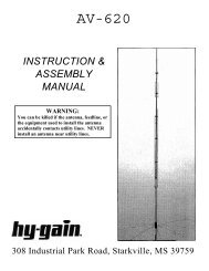
INSTALLATIONLINEAR AMPLIFIER INTERFACINGThe <strong>FT</strong>-<strong>857D</strong> provides the switching and drive-control lines required for easy interfacing tomost all commonly-available amplifiers sold today.These include: The Antenna Jacks (“HF/50MHz” and “144/430MHz”); A T/R control line (open circuit on RX, closure to ground on TX); and A negative-going ALC jack (control voltage range: 0V to –4V DC). When interfacing to the VL-1000 Solid State 1 KW Linear Amplifier, the optional CT-58 Interface Cable provides for easy interconnection (requires that the Menu Mode No-020 [CAT/LIN/TUN] setting changes to “LINEAR”).The rear-panel CAT/LINEAR jack is an 8-pin, miniature DIN type, with the “TX GND” pinproviding a closure to ground on transmit, for T/R control of your linear amplifier. The ACCjack is a miniature stereo type, with external ALC input capability on the tip connection. Themain shaft is the ground return. The ring connection of the ACC jack, when closed to ground,places the <strong>FT</strong>-857 into the transmit mode, and sends a steady CW carrier, for amplifier (orantenna tuner) adjustment purposes.Note that some amplifiers, particularly VHF or UHF “brick” amplifiers, offer two methodsof T/R switching: application of +13V or a closure to ground.Be sure to configure your amplifier so that it switches via a closure to ground, as providedby your <strong>FT</strong>-<strong>857D</strong>’s CAT/LINEAR jack (“TX GND” pin). Alternatively, many of theseamplifiers use “RF Sensing” to control their relays; if yours is in this category, you may thenuse the T/R control line from the “TX GND”pin of the CAT/LINEAR jack for control ofyour HF linear amplifier, and RF sensing foryour VHF or UHF amplifier.To HF AntennaTo HF AntennaTo 50 MHz AntennaTo 144 / 430 MHz AntennaANT 1ANT 2ANT 1ANT 2ANT 3VL-1000REMOTEONOFFBAND DATA 1PTT 1PTT 2INPUT 1INPUT 2INPUT 1ALC 1ALC 2CONTROLDC48V INGNDBAND DATA 2CAT/LINEARCT-58 BAND DATA CableBAND-DATA 1ALC 1GNDDC 48V INCONTROLCT-58 ALC Cable16 <strong>FT</strong>-<strong>857D</strong> Operating Manual
INSTALLATIONLINEAR AMPLIFIER INTERFACINGThe “TX GND” T/R control line is a transistor “open collector” circuit, capable of handlingpositive amplifier relay coil voltages of up to +50V DC and current of up to 400 mA. If youplan on using multiple linear amplifiers for different bands, you must provide external bandswitchingof the “TX GND” relay control line from the CAT/LINEAR jack.Important Note!Do not exceed the maximum voltage or current ratings for the “TX GND” line at theCAT/LINEAR jack. This line is not compatible with negative DC voltages, nor ACvoltages of any magnitude.Most amplifier control relay systems require only low DC voltage/current switchingcapability (typically, +12V DC at 25 ~ 75 mA), and the switching transistor in the<strong>FT</strong>-<strong>857D</strong> will easily accommodate such amplifiers.CW KEY/KEYER CONNECTIONSAll commonly-available keyer paddles should work perfectly with the built-in ElectronicKeyer. The wiring configuration for the paddle is shown below.KEY GNDKEY GNDDOTDASHDOTC<strong>OM</strong>MONDASHC<strong>OM</strong>MONFor straight-key operation, only the tip and shaft connections are used.Note: Even when using a straight key, you must use a three-conductor (“stereo”) plug. If atwo-conductor plug is used, the key line will be constantly shorted to ground.When using an external electronic keyer, be absolutely certain that it is configured for “positive”keying, not “negative” or “grid block” keying. The “key-up” voltage of the <strong>FT</strong>-<strong>857D</strong>is +5V, and the “key-down” current is only about 1 mA.For CW automated keying using a personal computer, with an external memory keyer providingfor manual sending, it usually is possible to connect the keyed lines together via a“Y” connector. Check with the documentation accompanying your keyer and your contest/DX software for any cautions which need to be observed.<strong>FT</strong>-<strong>857D</strong> Operating Manual17
INSTALLATIONRECEIVER ACCESSORIES (TAPE RECORDER ETC.)Connection of a tape recorder or other such receiver accessory iseasily accomplished by using the DATA jack’s Data Out (1200 bps)terminal (Pin 5) and Ground (Pin 2). The audio output is fixed at100 mV, with an impedance of 600 Ω.ADJUSTING THE FRONT FEETThe two front feet of the transceiver allow the transceiver to be tilted upward for betterviewing. Simply fold both feet forward to raise the front of the transceiver, and fold themback against the bottom case to lower the front of the <strong>FT</strong>-<strong>857D</strong>.GNDDATADATA OUT1200bps18 <strong>FT</strong>-<strong>857D</strong> Operating Manual
INSTALLATIONNOTE<strong>FT</strong>-<strong>857D</strong> Operating Manual19
FRONT PANEL CONTROL & SWITCHESH<strong>OM</strong>EAFSELECTSQL/RFCLARFUNCAF KnobThe (inner) VOL knob adjusts the receiver audio volume level presented to the internalor external speaker. Clockwise rotation increases the volume level.SQL/RF KnobIn the USA version, this (outer) SQL/RF knob adjusts the gain of the receiver’s RF andIF stages. Using Menu Mode No-080 [SQL/RF GAIN], this control may be changed tofunction as a Squelch control, which may be used to silence background noise when nosignal is present. In the other versions, its default setting is set to “Squelch.”SELECT knobThis detented rotary switch is used for VFO frequency tuning, memory selection, andfunction selection for the [A], [B], [C] keys of the transceiver.H<strong>OM</strong>E KeyPressing this key momentarily recalls a favorite “Home” frequency memory.CLAR KeyPressing this key activates the Receiver Clarifier feature. When this feature is activated,the SELECT knob is used to set a tuning offset of up to ±9.99 kHz. The transmitter’sfrequency is not affected by the setting of the Clarifier.Press and hold in this key for one second to activate the IF Shift feature, which allowsyou to use the SELECT knob to adjust the center frequency of the IF filter’s passbandresponse.20 <strong>FT</strong>-<strong>857D</strong> Operating Manual
FRONT PANEL CONTROL & SWITCHESFUNC KeyPress this key momentarily to enable the changing of the function of the Multi Functionkeys ([A], [B], and [C]) by rotating the SELECT knob.Press and hold in this key for one second to activate the “Menu” mode.Multi Function KeysThese three keys select many of the most important operating features of the transceiver.When you press the [FUNC] key, then rotate the SELECT knob, the currentfunction of that key will appear above each of the [A], [B], and [C] keys (along thebottom of the LCD). You may scroll the display through 17 rows of functions availablefor use via the [A], [B], and [C] keys. The available features are shown in page 24.MODE(⊳)/MODE() KeyPressing either of these keys momentarily will change the operating mode. The selectionsavailable are:..... LSB USB CW CWR AM FM DIG PKT LSB .....DSP ButtonPressing this button momentarily provides instant access to Multi Function Row “p”(MFp), which contains the command key for the receiver’s Digital Signal Processingsystem. The available functions will appear as the functions displayed above the [A],[B], and [C] keys, as described previously. Pressing this key once more will returnoperation to the last-used Multi-Function Row (the one in use before the DSP row wasengaged).Press and hold in this switch for one second to activate Menu Item No-048, for adjustmentof the DSP Microphone Equalizer (see page 51 for details).POWER SwitchPress and hold in the POWER switch for one second to turn to the transceiver on or off.While the transceiver is turned on, pressing this switch momentarily will engage the“Fast Tuning” mode, to allow more rapid frequency navigation (a small “running man”icon will be observed in the bottom right-hand corner of the LCD).TX/BUSY IndicatorThis indicator glows green when the squelch opens, and turns red during transmit. DuringCW operation, this indicator will glow blue when an incoming signal is tuned to thecenter of the passband (with IF Shift off). And during FM reception, this indicator willglow blue when a signal is received with a CTCSS/DCS tone matching that to whichyour transceiver is set.<strong>FT</strong>-<strong>857D</strong> Operating Manual21
FRONT PANEL CONTROL & SWITCHESH<strong>OM</strong>EAFSELECTSQL/RFCLARFUNCBAND(DWN)/BAND(UP) KeyPressing either of these keys momentarily will cause the frequency to be moved up ordown by one frequency band. The selections available are:..... 1.8 MHz 3.5 MHz 5.0 MHz 7.0 MHz 10 MHz 14 MHz 15 MHz 18 MHz 21 MHz 24 MHz 28 MHz 50 MHz 88 MHz 108 MHz 144 MHz 430 MHz 1.8 MHz .....Recalling the 5 MHz band (U.S. model) requires different procedure. See page 38 fordetails.V/M KeyPressing this key switches frequency control between the VFO and Memory Systems.Press and hold in this key to store the contents of the VFO into the QMB (Quick MemoryBank) register.LOCK KeyPressing this key locks the front panel keys so as to prevent accidental frequency change.The LOCK key itself, though, will never be disabled.MAIN DIALThis is the main tuning dial for the transceiver. It is used both for frequency tuning aswell as “Menu” setting in the transceiver.Liquid Crystal DisplayThe Liquid Crystal Display (LCD) provides indication of the operating frequency andother aspects of transceiver status.22 <strong>FT</strong>-<strong>857D</strong> Operating Manual
FRONT PANEL CONTROL & SWITCHESMIC JackConnect the supplied MH-31A8J Hand Microphone to this jack.SP-PH SwitchIf you use earphones with this transceiver, move this switch to the “PH” position beforeinserting the earphone plug into the SP/PH Jack, to prevent injury your ears.METER JackThis 3.5-mm 2-pin jack is used for connection to an analog meter (notproduced by Vertex Standard). Please refer to the MENU, No-060 andNo-061.SP/PH JackThis 3.5-mm, 2-pin jack provides variable audio output for an externalspeaker (4 Ω ~ 16 Ω impedance) or earphones. The audio level variesSIGNAL GNDaccording to the setting of the front panel’s AF knob.Important Note: When you insert an earphone plug into this jack, the SP-PH slideswitch (located on the back side of front panel) MUST BE set to the “PH” position, toprevent the possibility of injury to your ears.CONTROL JackSIGNALGNDMAIN BODY (FRONT)CONTROL JackPHSPFRONT PANEL (BACK)<strong>FT</strong>-<strong>857D</strong> Operating Manual23
FRONT PANEL CONTROL & SWITCHESMULTI FUNCTION KEY DETAILThe [A], [B], and [C] keys select many of the mostimportant operating features of the transceiver. Whenyou press the [FUNC] key, then rotate the SELECTknob, the current function of that key will appearabove each of the [A], [B], and [C] keys (along thebottom of the LCD). You may scroll the displaythrough 17 rows of functions available for use via the[A], [B], and [C] keys.SELECT[FUNC][A][B][C]DIAL [A] [B] [C] [A] [B] [C]Multi Function Row “a” (MFa) [A/B, A=B, SPL][A] Key: A/BPress the [A](A/B) key to switch between VFO-A and VFO-B on thedisplay.[B] Key: A=BPress the [B](A=B) key to copy the contents of Main VFO to be copiedinto the Sub VFO, so that the two VFOs’ contents will be identical.[C] Key: SPLPress the [C](SPL) key to activate Split frequency operation betweenVFO-A and VFO-B.Multi Function Row “b” (MFb) [MW, SKIP, TAG][A] Key: MWPress this key momentarily to enable the “Memory Check” mode, toallow selection of an empty memory channel prior to frequency storage.Press and hold in the [A](MW) key for one second to transfer thecontents of the VFO into the selected Memory register.[B] Key: SKIPPress the [B](SKIP) key to designate the current Memory channel tobe “skipped” during scanning.[C] Key: TAGPress the [C](TAG) key to select the display type (Frequency or Alpha-numericTag) during Memory operation. Press and hold in thiskey for one second, while on a recalled channel, to open Menu No.-056, for quick programming of an Alphanumeric Tag.24 <strong>FT</strong>-<strong>857D</strong> Operating Manual
FRONT PANEL CONTROL & SWITCHES [A] [B] [C] [A] [B] [C]MULTI FUNCTION KEY DETAILMulti Function Row “c” (MFc) [STO, RCL, PROC][A] Key: STOPress the [A](STO) key to store the contents of the VFO into the QMB(Quick Memory Bank) register.[B] Key: RCLPress the [B](RCL) key to recall the QMB Memory.[C] Key: PROCPress the [C](PROC) key to activate the speech processor for SSB andAM transmission.Press and hold in the [C](PROC) key for one second to recall MenuMode No-074 [PROC LEVEL] (for setting the compression level ofthe AF Speech Processor).Multi Function Row “d” (MFd) [RPT, REV, VOX][A] Key: RPTPress the [A](RPT) key to select the direction of the uplink frequencyshift (+, – or simplex) during FM repeater operation.Press and hold in the [A](RPT) key for one second to recall MenuMode No-076 [RPT SHI<strong>FT</strong>] (for setting the shift frequency offset).[B] Key: REVPress the [B](REV) key to reverse the transmit and receive frequencieswhile working through a repeater.[C] Key: VOXPress the [C](VOX) key enable the VOX (voice-operated transmitterswitching system) in the SSB, AM, and FM modes.Press and hold in the [C](VOX) key for one second to recall MenuMode No-088 [VOX GAIN] (for setting the VOX gain level).<strong>FT</strong>-<strong>857D</strong> Operating Manual25
FRONT PANEL CONTROL & SWITCHESMulti Function Row “e” (MFe) [TON, –––, TDCH] ([ENC, DEC, TDCH])[A] Key: TON/ENCPress the [A](TON) key to activate CTCSS or DCS operation on FM.When the Split Tone feature is activated via Menu Mode No-079[SPLIT TONE], this key function changes to “ENC” for activation of [A] [B] [C] [A] [B] [C] [A] [B] [C] [A] [B] [C]MULTI FUNCTION KEY DETAILthe CTCSS Encoder or DCS Encoder. Press the [A](ENC) key to activatethe encoder.Press and hold in the [A](TON/ENC) key for one second to recall MenuMode No-083 [TONE FREQ] (for selecting the CTCSS tone frequency).[B] Key: –––/DECNormally, this key does nothing.When the Split Tone feature is activated via Menu Mode No-079[SPLIT TONE], this key function changes to “DEC” to engage the DCSor CTCSS Decoder. Press the [B](DEC) key to activate the decoder.Press and hold in the [B](DEC) key for one second to recall MenuMode No-033 [DCS CODE] (for selecting the DCS code).[C] Key: TDCHPress the [C](TDCH) key to initiate CTCSS Tone or DCS Search.Multi Function Row “f” (MFf) [ARTS, SRCH, PMS][A] Key: ARTSPress the [A](ARTS) key to initiate the Auto-Range Transponder mode.Press and hold in the [A](ARTS) key for one second to recall MenuMode No-008 [ARTS BEEP] (for selecting the ARTS “Beep” option).[B] Key: SRCHPress the [B](SRCH) key to activate the Smart Search feature.Press the [B](SRCH) key to initiate Smart Search scanning.[C] Key: PMSPress the [C](PMS) key to activate the Programmable Memory Scanfeature (programmable sub-band limits for tuning or scanning).Multi Function Row “g” (MFg) [SCN, PRI, DW][A] Key: SCNPress the [A](SCN) key to initiate Scanning (in the direction of higherfrequencies).[B] Key: PRIPress the [B](PRI) key to activate the Priority Scan feature.[C] Key: DWPress the [C](DW) key to activate the Dual Watch feature.26 <strong>FT</strong>-<strong>857D</strong> Operating Manual
FRONT PANEL CONTROL & SWITCHES [A] [B] [C] [A] [B] [C] [A] [B] [C]MULTI FUNCTION KEY DETAILMulti Function Row “m” (MFm) [IPO, ATT, NAR][A] Key: IPOPress the [A](IPO) key to bypass the receiver preamplifier, therebyactivating Intercept Point Optimization for improved overload characteristicswhile operating on the HF and 50 MHz bands.The IPO feature does not function on 144/430 MHz.[B] Key: ATTPress the [B](ATT) key to engage the receiver front-end attenuator,which will reduce all signals and noise by approximately 10 dB.The ATT feature does not function on 144/430 MHz.[C] Key: NARPress the [C](NAR) key to select the low-deviation mode for HF FMoperation on 29 MHz.Multi Function Row “n” (MFn) [CFIL,–––,–––][A] Key: CFILPress the [A](CFIL) key to select the 2.4 kHz ceramic IF filter.[B] KeyPress the [B] key to select the optional IF filter which is located on the“FIL-1” (Optional Filter 1) slot on the Main Unit.When an optional filter is not installed on the “FIL-1” slot, this keyfunction is disabled, and its label is “N/A.”[C] KeyPress the [C] key to select the optional IF filter which is located on the“FIL-2” (Optional Filter 2) slot on the Main Unit.When an optional filter is not installed on the “FIL-2” slot, this keyfunction is disabled, and its label is “N/A.”Multi Function Row “o” (MFo) [PLY1, PLY2, PLY3][A] Key: PLY1Press the [A](PLY1) key to send the CW message which is memorizedin Keyer BEACON TEXT 1.Press and hold in the [A](PLY1) key for one second to recall MenuMode No-011 [BEACON TEXT 1] (for stores the message for the Beacon).[B] Key: PLY2Press the [B](PLY2) key to send the CW message which is memorizedin Keyer BEACON TEXT 2.[C] Key: PLY3Press the [C](PLY3) key to send the CW message which is memorizedin Keyer BEACON TEXT 3.<strong>FT</strong>-<strong>857D</strong> Operating Manual29
FRONT PANEL CONTROL & SWITCHES [A] [B] [C]Multi Function Row “p” (MFp) [DNR, DNF, DBF][A] Key: DNRPress the [A](DNR) key to activate the DSP Noise Reduction system .Press and hold in the [A](DNR) key for one second to recall MenuMode No-049 [DSP NR LEVEL] (for setting the degree of DSP NoiseReduction).[B] Key: DNFPress the [B](DNF) key to activate the DSP’s Auto Notch Filter.[C] Key: DBFPress the [C](DBF) key to activate the DSP’s receiver Bandpass Filter.In the SSB, AM, FM, and AFSK modes, press and hold in the [C](DBF)key for one second to recall Menu Mode No-047 [DSP LPF CUTOFF](for adjusting the high-frequency cutoff of the DSP Bandpass Filter).Once there, rotating the SELECT knob one click counter-clockwisewill select Menu Mode No-046, for adjustment of the low-frequencycutoff frequency.In the CW mode, press and hold in the [C](DBF) key for one secondto recall Menu Item No-045 [DSP BPF WIDTH] (for setting the CWbandwidth).Multi Function Row “q” (MFq) [MONI, QSPL, ATC] (Programmable Keys)[A] Key: MONIPress the [A](MONI) key to disable the Noise Squelch.You may program the configuration of this key via Menu Item No-065 [PG A]. [A] [B] [C]MULTI FUNCTION KEY DETAIL[B] Key: QSPLPress the [B](QSPL) key to activate the “Quick Split” feature, wherebyyou will change the Sub VFO frequency to be the Main VFO frequency+ 5 kHz; you will also automatically engage the “Split VFO”feature.You may program the configuration of this key via Menu Item No-066 [PG B].[C] Key: ATCPress the [C](ATC) key to activate a 1750-Hz burst tone for 2 secondswhen pressing the PTT switch while the channel is clear.You may program the configuration of this key via Menu Item No-067 [PG C].30 <strong>FT</strong>-<strong>857D</strong> Operating Manual
FRONT PANEL CONTROL & SWITCHESLCDCTCSS/DCS Status: CTCSS Encoder Active (Split Tone “ON”): CTCSS Encoder Active (Split Tone “OFF”): CTCSS Encoder/DCS Decoder Active (Split Tone “ON”): CTCSS Encoder/Decoder (Tone Squelch) Active (Split Tone “ON”): DCS Encoder Active (Split Tone “ON”): DCS Encoder Active (Split Tone “OFF”): DCS Encoder/Decoder Active (Split Tone “ON”): DCS Encoder/CTCSS Decoder Active (Split Tone “ON”): CTCSS Encoder/Decoder (Tone Squelch) Active (Split Tone “OFF”): DCS Encoder/Decoder Active (Split Tone “OFF”)Operating Mode: Odd Split: Minus Shift: Plus ShiftAPO Active: IPO Active: ATT Active: VOX Active: Priority Active: Dual Receive Active: DSP Active: HI Temperature: HI SWR (more the 3.0)VFO-A/B orMemory Channel NumberS/PO MeterTransvert ModeSELECT knob Alternate FunctionSupply VoltageAntenna Tuner Status(See Below)Meter Status: S Meter: PO Meter: Modulation Meter: SWR Meter: ALC MeterMulti Function Key StatusOperating FrequencyAntenna Tuner Status: FC-30 Active: ATAS-100/-120 Active: Antenna Tuning Progress: ATAS-100/-120 Initializing: HI SWR (more than 3.0): ATAS-100/-120 out of tuning band: FC-30 out of tuning band: IF SHI<strong>FT</strong> Active: Clarifire Active: Key Lock “ON”/ : Fast Tuning Step<strong>FT</strong>-<strong>857D</strong> Operating Manual31
REAR PANEL CONNECTORSINPUT JackThis is the DC power supply connection for the transceiver. Use the supplied DC cableto connect this jack to the car battery or DC power supply,which must be capable of supplying at least 22 Amps @13.8 VDC. Make certain that the Red lead connects to thePositive (+) side of the power source, and that the Black BATT SENSlead connects to the Negative (–) side of the power source.This Jack also provides an Transmit Power Control terminal. If you connect pin-3 (BATTSENS) of the DC power jack to the ground, the <strong>FT</strong>-<strong>857D</strong> automatically switches to 20Watts (430 MHz: 10 Watts) of output power.CAT/LINEAR JackThis 8-pin mini-DIN jack is used for connection to the FC-30 External Automatic AntennaTuner. It is also used for interfacingto a personal computer forcontrol of the transceiver using theCAT system, and for interconnectionto the VL-1000 Linear Amplifier.TX INHRX DTX DTX GNDRESET+13.8VCAT/TUNERBAND DATA TX INHGND BAND BBAND ATX GNDBAND DLINEARBAND CGND+13.8V32 <strong>FT</strong>-<strong>857D</strong> Operating Manual
REAR PANEL CONNECTORSDATA JackThis 6-pin, mini-DIN jack accepts AFSK input from a TerminalNode Controller (TNC); it also provides fixed-levelReceiver Audio Output, Push-To-Talk (PTT), Squelch Status,and ground lines.DATA OUT9600bpsACC JackThis 3.5-mm 3-pin jack accepts external ALC (Automatic Level Control) voltage froma linear amplifier on the tip connection, and accepts a “Transmit Request” command onthe ring connection. The main shaft is the ground return.The “TX Request” connection, when shorted to ground, puts the <strong>FT</strong>-<strong>857D</strong> into the transmit mode, and sends out a steady CW carrier, forlinear amplifier or manual antenna tuner adjustment.DATADATA OUT1200bpsKEY JackThis 3.5-mm, 3-pin jack is used for connection to a CW keyer paddle or a straight key.EXT SPKR JackThis 3.5-mm, 2-pin jack provides variable audio output for an external speaker. Theaudio output impedance at this jack is 4 Ω ~ 16 Ω and the level variesaccording to the setting of the front panel’s AF control.144/430 MHz Antenna JackConnect your 144 and/or 430 MHz antenna’s 50 Ω coaxial cable to this M-type (“SO-239”) connector (European versions are equipped with a type-N connector).HF/50 MHz Antenna JackConnect your HF and/or 50 MHz antenna’s 50 Ω coaxial cable to this M-type (“SO-239”) connector.SQLGNDEXT ALCSIGNALPTTDATA INGNDTX REQGNDKEY GNDKEY GNDDOTDASHDOTC<strong>OM</strong>MONDASHC<strong>OM</strong>MON<strong>FT</strong>-<strong>857D</strong> Operating Manual33
OPERATIONHi! I’m R.F. Radio, and I’m here to guide you through the fine points of the setupand use of your new <strong>FT</strong>-<strong>857D</strong>. I know you’re anxious to get on the air, but Iencourage you to read the “Operation” section of this manual as thoroughly as possible,so you’ll get the most out of this fantastic new rig. Now. . .let’s get operating!TURNING THE TRANSCEIVER ON AND OFF To turn the transceiver on, press and hold in thePOWER switch for one second. To turn the transceiver off, again press and hold inthe POWER switch for one second.POWEROPERATING BAND SELECTIONThis transceiver covers an incredibly wide frequency range, over which a number of differentoperating modes are used. Therefore, this transceiver’s frequency coverage has beendivided into different operating bands, each of with has its own pre-set frequency steps andoperating modes. You can change the channel steps and operating mode once you get started,of course, per the next section.To change the frequency band, press either the[BAND(DWN)] or [BAND(UP)] key to move to thenext lower or higher operating band, respectively.1) Recalling the 5 MHz band (U.S. model) requiresdifferent procedure. See page 38 fordetails.2) VFOa and VFOb are independent VFOs, so they may be set to different bands. See the“Stacked VFO System” discussion on page 37 for details.MODE SELECTIONPress either the [MODE(⊳)] or [MODE()] key to move among the eight settings for theoperating modes, respectively...... LSB USB CW CWR AM FM DIG PKT LSB .....where “CWR” is “CW-Reverse,” using the oppositesideband from the “default” BFO injection sideband(in most cases, the default injection sideband is on the“USB” side); “DIG” is an AFSK-based Digital mode,set up per Menu Mode No-038 [DIG MODE]; and“PKT” represents either 1200 or 9600 bps FM packet.[MODE()][( ) MODE]34 <strong>FT</strong>-<strong>857D</strong> Operating Manual
MODE SELECTIONYou can set VFOa and VFOb to different modes in the same band, allowing you tohave a “Phone” VFO and a “CW” VFO, for example.ADJUSTING THE AUDIO VOLUME LEVELRotate the AF knob to set a comfortable listening level.When operating in the “DIG” or “PKT” modes, youmay set the AF knob to any comfortable setting, oreven all the way off, because the output from the DATAjack is a fixed-level audio signal.OPERATIONStart with the AF knob set fully counter-clockwise, especially when using FM (thebackground noise on FM can be surprisingly loud)!AFMENU QUICK STARTMany aspects of this transceiver’s configuration may be customized using the convenient“Menu” system, which allow you to configure many “set and forget” settings just the wayyou want to. A full discussion of the Menu system begins on page 94; for now, here is a briefdiscussion on how to change Menu settings:1. Press and hold in the [FUNC] key for one secondto enter the Menu mode.2. Rotate the SELECT knob to recall the Menu Itemto be changed (for example, Menu Mode No-005[AM MIC GAIN], which allows setting of the MicGain for the AM mode).3. Rotate the DIAL knob to set this feature (in thisSELECT] [FUNCDIALexample, the default setting is “50,” so rotate the DIAL knob if you want to raise orlower the Mic Gain level.4. Press and hold in the [FUNC] key for one second to save the new setting and exit tonormal operation.If you had previously pressed the [FUNC] key to enable the changing of the functionof the Multi Function keys ( [A], [B], and [C] ) by the SELECT knob, you’llneed to press it again after exiting the Menu mode.<strong>FT</strong>-<strong>857D</strong> Operating Manual35
OPERATIONADJUSTING THE RF GAIN AND SQUELCHThe SQL/RF Gain control is configured differently, SQL/RFdepending on the country to which the <strong>FT</strong>-<strong>857D</strong> hasbeen exported. In the U.S. version, the default functionof this control is “RF Gain.” The configuration ofthe SQL/RF Gain control is set via Menu Mode No-080 [SQL/RF GAIN]; see page 110 for details.If your transceiver is configured for “RF Gain” use, rotating this control fully clockwise inthe SSB/CW/Digital modes will provide best sensitivity. To reduce the receiver’s RF Gainsomewhat, rotate this control counter-clockwise slightly. You will observe an increasingnumber of bars on the S-meter as you rotate the RF Gain control counter-clockwise; thisindicates increasing AGC voltage, which is causing the front-end gain to be reduced. In theFM and Packet modes, with “RF Gain” selected, the <strong>FT</strong>-<strong>857D</strong> goes into an “Auto Squelch”mode, with the Squelch level being preset at the factory.If this control is configured for “SQL” operation, the <strong>FT</strong>-<strong>857D</strong>’s RF Gain will be set formaximum sensitivity in all modes, and the SQL/RF Gain control will function solely as aSquelch control. In this case, rotate the SQL/RF Gain control to the point where the backgroundnoise is just silenced; this will provide the best sensitivity to weak signals, whilekeeping the receiver quiet when no signal is received. The LED just above the Main DIALwill glow Green when the squelch is opened by an incoming signal or noise.SETTING THE OPERATING FREQUENCY1. In the “SSB/CW/DIG” modes, rotate the DIAL knob to set the frequency. Clockwiserotation of the DIAL increases the operating frequency.2. In the “AM/FM/PKT” modes, rotate the SELECTknob to set the frequency. Clockwise rotation ofthe SELECT knob increases the operating frequency.SELECTDIAL3. You may also use the SELECT knob to adjust the operating frequency in the “SSB/CW/DIG” modes. The SELECT knob provides faster tuning, ideal for making quick changesin frequency when you want to move across the band in a hurry. You can then use theDIAL knob to make fine frequency adjustments.The synthesizer steps for the SELECT knob may be adjusted independently by mode. UseMenu Mode No-006 [AM STEP] for AM, No-052 [FM STEP] for FM, and No-082 [SSBSTEP] for SSB/CW/DIG. See pages 97, 105, and 110 for details.If you press the SELECT knob momentarily, then rotate the SELECT knob, you can now36 <strong>FT</strong>-<strong>857D</strong> Operating Manual
SETTING THE OPERATING FREQUENCYOPERATIONchange the operating frequency in 1 MHz steps, allowing very quick frequency excursions.This can be particularly helpful on the VHF and UHF bands.In step 2 above, it was mentioned that tuning in the “AM/FM/PKT” modes is accomplishedusing the SELECT knob. By default, the DIAL is disabled in these modes; if you wish toenable the DIAL in these modes, use Menu Mode No-004 [AM&FM DIAL]; see page 97.The main DIAL synthesizer’s tuning rate (the number of steps per rotation of theDIAL) can be adjusted using Menu Mode No-035 [DIAL STEP]. See page 102 fordetails.CHANGING THE DIAL SPEEDBy default, the <strong>FT</strong>-857 begins operation in the “fine tuning” mode for the main tuning dial.However, a faster tuning rate may be selected, for quick navigation up and down the band.To engage the “Fast Tuning” mode, just press the POWER switch momentarily while thetransceiver is on. You will observe a small “ ” icon inPOWERthe bottom right-hand corner of the LCD, and as yourotate the main tuning dial you will notice that the tuningrate has increased significantly. Press the POWERswitch momentarily once more to return to the “SlowTuning” mode (the small “ ” will disappear).STACKED VFO SYSTEMPress the [FUNC] key momentarily, then rotate the SELECT knob, as needed, until MultiFunction Row “a” [A/B, A=B, SPL] appears on the display.Now press the [A](A/B) key to toggle between the “A” and “B” VFOs. There are two suchVFOs provided on each Amateur band, so you may set VFO-A to the CW sub-band, andVFO-B to the SSB sub-band, if you like. The operating mode will be preserved, along withthe frequency information, on each VFO.When changing bands on either the “A” or “B” VFO, the two VFOs do not changebands together. This facilitates split-band operation, such as on FM satellites.<strong>FT</strong>-<strong>857D</strong> Operating Manual37
OPERATIONOPERATION ON 5 MHZ BAND (U.S. VERSION ONLY)The <strong>FT</strong>-<strong>857D</strong> includes the capability for transmission and reception on the five spot frequenciesassigned to the Amateur Service in the United States. To operate on the 5 MHzband:1. Press the [M/V] key once to enter the “Memory” mode (a memory channel number “Mnnn”will appear on the display in the space previously occupied by “VFOa” or “VFOb”).2. Memory channels “M-601” through “M-605” are pre-programmed,at the factory, with the permitted frequencies in the 5MHz band, and the USB mode is automatically selected on thesechannels.If you have partitioned your memory channels into MemoryCH No.M-601M-602M-603M-604M-605FREQUENCY5.332 MHz5.348 MHz5.368 MHz5.373 MHz5.405 MHzGroups via Menu Mode No-055 [MEM GROUP], the memory channel numbers for 60-meter operation will be displayed as “Ml - 001” ~ “Ml - 005.” See page 76 for detailsregarding Memory Group operation, and page 106 for details regarding Menu Mode No-055 [MEM GROUP].3. To exit from 60-meter operatin and return to the VFO mode, just press the [M/V] key(the memory channel number will be replaced by “VFOa” or “VFOb”).The frequencies and operating mode for 5 MHz band operation are both fixed,and may not be changed.38 <strong>FT</strong>-<strong>857D</strong> Operating Manual
RECEIVER ACCESSORIESLOCKING FRONT PANEL CONTROLSThe front panel LOCK button allows you todisable the DIAL and/or the front panel controls.[ LOCK]In the transceiver’s default configuration,pressing the [LOCK] button disables just the DIAL, while the other keys and switches areunaffected. To lock out the remainder of the controls and the SELECT knob, use MenuMode No-054 [LOCK MODE]:1. Press and hold in the [FUNC] key for one second to enter the Menu mode.2. Rotate the SELECT knob to recall Menu Mode No-001 [EXT MENU], then rotate theDIAL to change the setting to “ON” to enable the extended Menu Mode.3. Rotate the SELECT knob so as to recall No-054 [LOCK MODE].4. Rotate the DIAL to select the desired configuration:DIAL: Locks DIAL knob only.FREQ: Locks front panel keys and knobs related to frequency control (such asBAND(DWN) and BAND(UP) key, [A](A/B) key., etc.).PANEL: Locks all front panel keys and knobs (except POWER and [LOCK] keys).ALL: Locks all front panel keys and knobs (except POWER and [LOCK] keys) andlocks the microphone keys.5. When you have made your selection, press and hold in the [FUNC] key for one secondto save the new setting and exit to normal operation.When the controls are locked out (small “ ” icon will appear at the bottom right-handcorner of the LCD), press the LOCK button once more to release them to normal operation.<strong>FT</strong>-<strong>857D</strong> Operating Manual39
RECEIVER ACCESSORIESCLARIFIER (RECEIVER INCREMENTAL TUNING)The Clarifier (RIT) allows you to set an offset of up to ±9.99 kHz of the receive frequencyrelative to your transmit frequency. To achieve a wider offset than this, you may use the“Split” operating mode, described later.1. Press the [CLAR] button momentarily to activate SELECTthe Clarifier function.2. Turn the SELECT knob, which allows the receiverfrequency to be varied over a range of ±9.99 kHz.3. When the receiving frequency is higher than transmitfrequency, the “ (within 1 kHz)” or “ (beyond1 kHz)” icon will appear to the right of the [CLAR]frequency display. Similarly, when the receiving frequencyis lower than transmit frequency, the “ (within 1 kHz)”or “ (beyond 1 kHz)” icon will appear to the right of thefrequency display. When the receiving frequency is equalto transmit frequency (Clarifier offset is zero) while theClarifier is activated, the “ ” icon will appear to the rightof the frequency display.4. To turn the Clarifier off, again press the [CLAR] buttonmomentarily. When you turn the Clarifier back on, theoffset previously stored will still be applied.5. To reset the Clarifier offset to zero, turn the Clarifier off,then turn the DIAL by any amount. The Clarifier will resetto zero after the first “step” of the DIAL.1) If you leave the Clarifier on, moving the DIALwill not cause the offset to be cancelled.2) You may change the knob that controls the Clarifier offsetfrom the DIAL to the SELECT knob via Menu ModeNo-021 [CLAR DIAL SEL].[TXRX (exceed 1 KHz)]40 <strong>FT</strong>-<strong>857D</strong> Operating Manual
IF SHI<strong>FT</strong>The receiver’s IF SHI<strong>FT</strong> feature is an effective interference-reduction tool, which allowsyou to shift the passband response higher or lower without changing the pitch of the incomingsignal.1. Press and hold in the [CLAR] button for one secondto activate the IF SHI<strong>FT</strong> feature. An icon, suchSELECTas “ ”, “ ” (slightly shifted to the upper side),“ ” (more shifted to the upper side), “ ”(slightlyshifted to the lower side),” or “ ” (more shifted tothe lower side)” icon will appear at the right of thefrequency display to indicate the IF SHI<strong>FT</strong>’s currentposition.[CLAR]2. Rotate the SELECT knob, as needed, to reduce or eliminatethe interference.3. To turn the IF SHI<strong>FT</strong> feature off, again press and hold inthe [CLAR] button for one second. The last setting of theIF SHI<strong>FT</strong> control will be retained until you change it again.If you wish to make a more permanent shift in the receiver’sIF passband, use Menu Mode No-015 [CAR LSB R] (for LSBmode) or No-017 [CAR USB R] (for USB mode). This allowsyou to set up a higher or lower listening pitch, if youprefer such as compared to the default passband response.See page 99.RECEIVER ACCESSORIES(more shifted to the upper side)(slightly shifted to the upper side)(slightly shifted to the lower side)(more shifted to the lower side)<strong>FT</strong>-<strong>857D</strong> Operating Manual41
RECEIVER ACCESSORIESAGC (AUT<strong>OM</strong>ATIC GAIN CONTROL)The receiver recovery time constant of the AGC system may be modified to match youroperating needs.1. Press the [FUNC] key momentarily, then rotate the SELECT knob, as needed, untilMulti Function Row “l” [NB, AGC, AUTO] appears on the display.2. Press the [C] key to toggle the AGC recovery time constant among the following selections:AUTO FAST SLOW AUTO > .....where “AUTO” represents “FAST” on CW and DIG (AFSK), and “SLOW” on the voicemodes.If you disable the AGC by pressing the [B](AGC) key (to make the parenthesesdisappear), the S-meter (which monitors AGC voltage) will cease to function.Depending on the setting of the RF Gain control, incoming signals will probably be distortedif the AGC is turned off.NOISE BLANKERThe IF Noise Blanker may be useful in reducing or eliminating some types of impulse noise,especially noise generated by automotive ignition systems.1. Press the [FUNC] key momentarily, then rotate the SELECT knob, as needed, untilMulti Function Row “l” [NB, AGC, OFF] appears on the display.2. Press the [A](NB) key to activate the Noise Blanker. The “” icon will appear at the leftside of the “NB” selection, indicating that the Noise Blanker is now on.3. To adjust the blanking level, press and hold in the [A](NB) key for one second. Thisinstantly activates Menu Mode No-063 [NB LEVEL], which allows adjustment of NoiseBlanking Level. Rotate the DIAL knob to set a higher or lower blanking level (on a scaleof 0 to 100). When done, press and hold in the [FUNC] key for one second to save thenew setting and return to normal operation.4. Press the [A](NB) key again to turn the Noise Blanker off.During very crowded band conditions, you may wish to turn the Noise Blankeroff, as its use will degrade the strong-signal-handling capability of the receiversomewhat.42 <strong>FT</strong>-<strong>857D</strong> Operating Manual
RECEIVER ACCESSORIESIPO (INTERCEPT POINT OPTIMIZATION)The IPO feature bypasses the receiver RF preamplifier, thereby eliminating the preamp’sgain. This feature is not available on the 144 MHz and 430 MHz bands.1. Press the [FUNC] key momentarily, then rotate the SELECT knob, as needed, untilMulti Function Row “m” [IPO, ATT, NAR] appears on the display.2. Press the [A](IPO) key to bypass the receiver input preamplifier. The “” icon willappear at the left side of the “IPO” selection, and the “ ” icon will appear on the display.indicating that the preamp is now disengaged from the receiver circuit.3. Press the [A](IPO) key once more to re-activate the preamp.On the bands below 14 MHz, the input preamplifier is rarely necessary, and activationof the IPO feature will provide substantial protection against intermodulationand other problems associated with strong signal input to the receiver. Rule of thumb: solong as the S-meter is moving on background noise, additional front-end gain is notnecessary.ATT (FRONT END ATTENUATOR)The Attenuator will reduce all signals (and noise) by 10 dB, and it may be used to makereception more pleasant under extremely noisy conditions. This feature is not available onthe 144 MHz and 430 MHz bands.1. Press the [FUNC] key momentarily, then rotate the SELECT knob, as needed, untilMulti Function Row “m” [IPO, ATT, NAR] appears on the display.2. Press the [B](ATT) key to activate the Attenuator. The “” icon will appear at the leftside of the “ATT” selection, and the “ ” icon will appear on the display.3. Press the [B](ATT) key once more to switch the Attenuator out of the receiver front endcircuit. Signals will again be received at a level 10 dB louder than was the case when theAttenuator was engaged.<strong>FT</strong>-<strong>857D</strong> Operating Manual43
RECEIVER ACCESSORIESDSP BANDPASS FILTER (DBF)In the SSB mode, the receiver’s selectivity may be enhanced via the DSP Bandpass Filter.1. Press the [DSP] key momentarily. This instantly activates Multi Function Row “p” [DNR,DNF, DBF].2. Press the [C](DBF) key to activate the DSP Bandpass Filter. The “” icon will appear atthe left side of the “DBF” selection, and the “ ” notation will appear at the top of thedisplay, to the right of the center. You will notice a decrease in both background noiseand interference, if any is present.3. The bandwidth of the DSP filter may be modified, to customize the bandwidth to youroperating needs. To adjust the Low-Cut and High-Cut characteristics of the DSP BandpassFilter: Press and hold in the [C](DBF) key for one second. This instantly activates MenuMode No-047 [DSP LPF CUTOFF], which allows adjustment of the High-Cut (Low-Pass) filter. Turn the DIAL, as desired, to adjust the high-frequency cutoff of the DSP BandpassFilter. Now rotate the SELECT knob one click counter-clockwise to select Menu ModeNo-046 [DSP HPF CUTOFF], which allows adjustment of the Low-Cut (High-Pass)filter. Turn the DIAL, as desired, to adjust the low-frequency cutoff of the DSP BandpassFilter. When done, press and hold in the [FUNC] key for one second to save the new setting(s)and return to normal operation.4. Press the [C](DBF) key once more to disable the DSP Bandpass Filter.44 <strong>FT</strong>-<strong>857D</strong> Operating Manual
RECEIVER ACCESSORIESDSP CW PEAKING FILTER (DBF)In the CW mode, pressing the [C](DBF) key in Multi Function Row “p” [DNR, DNF, DBF]activates a narrow-bandwidth peaking filter, which may be ideal for use under very crowdedconditions. The DSP CW Peaking Filter also is especially helpful under VHF/UHF weaksignalsituations.The center frequency of the DSP CW Peaking Filter is automatically aligned to be centeredon the response you have selected via the Menu Mode in item No-027 [CW PITCH]. Seepage 101 for details.1. To change the bandwidth of the DSP CW Peaking Filter:2. Press and hold in the [C](DBF) key for one second on the CW mode. This instantlyactivates Menu Mode No-045 [DSP BPF WIDTH], which allows selection of the bandwidthof the DSP CW Peaking Filter.3. Rotate the DIAL to select the desired bandwidth. The available values are 60 Hz, 120Hz, and 240 Hz (default value: 240 Hz).4. When you have made your selection, press and hold in the [FUNC] key for one secondto save the new setting and return to normal operation.DSP NOISE REDUCTION (DNR)The Noise Reduction feature of the DSP system may be used to enhance signal-to-noiseratio on weak signals.1. Press the [DSP] key momentarily. This instantly activates Multi Function Row “p” [DNR,DNF, DBF].2. Press the [A](DNR) key to activate the DSP Noise Reduction feature. The “” icon willappear at the left side of the “DNR” indication, and the “ ” notation will appear atthe top on the display.3. Now press and hold in the [A](DNR) key for one second. This instantly activates MenuMode No-049 [DSP NR LEVEL], which allows adjustment of the DSP Noise Reductionlevel.4. Rotate the DIAL to find the point where best signal-to-noise ratio is obtained under thecurrent noise conditions.5. Press and hold in the [FUNC] key for one second to save the new setting and exit tonormal operation.6. To turn off the DSP Noise Reduction feature, press the [A](DNR) key again.If noise is present at a level which causes indication on the S-meter, the performanceof the Noise Reduction filter may be enhanced by rotating the SQL/RF(RF Gain) control in a counter-clockwise direction so as to set the (fixed) S-meter readingat the same level as the noise peaks. This adjustment raises the AGC threshold of thereceiver.<strong>FT</strong>-<strong>857D</strong> Operating Manual45
RECEIVER ACCESSORIESDSP NOTCH FILTER (DNF)The DSP system’s Notch Filter may be helpful in removing one or more offending carrier orheterodyne signals from the audio passband.1. Press the [DSP] key momentarily. This instantly activates Multi Function Row “p” [DNR,DNF, DBF].2. Press the [B](DNF) key to activate the Notch Filter. The “” icon will appear at the leftside of the “DNF” indication, and the “ ” notation will appear at the top on thedisplay. You will notice that the audio level of the carrier signal is now being reduced.3. Press the [B](DNF) key once more to turn the Notch Filter off.Do not activate this filter in the CW mode, as incoming CW signals will be notchedout of the audio passband!AM/FM TUNING DIAL OPERATIONIn the AM and FM modes, the DIAL knob is locked out (via the setting of Menu Mode No-004 [AM&FM DIAL]) so as to allow “channelized” tuning on these modes. To adjust theoperating frequency, simply rotate the SELECT knob.If you wish to enable the DIAL for tuning in the AM and FM modes, change the setting ofMenu Mode No-004 [AM&FM DIAL]. See page 97 for details.The “channelized” mode of tuning on AM and FM automatically rounds off thefrequency to the next “logical” step when you rotate the SELECT knob one “click”in either direction. This eliminates the inconvenience of having to preset the frequency toan “even” channel.46 <strong>FT</strong>-<strong>857D</strong> Operating Manual
RECEIVER ACCESSORIESAUT<strong>OM</strong>ATIC POWER-OFF FEATUREThe APO feature helps conserve battery life by automatically turning the transceiver offafter a user-defined period of time within which there has been no dial or key activity. Theavailable selections for the time before power-off are 1 ~ 6 hours, as well as “APO Off.” Thedefault condition for the APO is OFF, and here is the procedure for activating it:1. Press and hold in the [FUNC] key for one second to enter the Menu mode.2. Rotate the SELECT knob to recall Menu Mode No-007 [APO TIME].3. Rotate the DIAL knob to select the desired time period after which the radio will automaticallyshut down.4. Press and hold in the [FUNC] key for one second to save the new setting and exit tonormal operation.Once you have programmed a time interval, the APO countdown timer will start wheneversome front panel action (tuning, transmission, etc.) is completed.When the APO is activated, the “ ” icon will appear at the center top on the LCD. If thereis no action by you within the time interval programmed, the microprocessor will shut downthe radio automatically.Just press and hold in the POWER switch for one second to turn the transceiver back onafter an APO shutdown, as usual.The APO feature will be disabled while using the Beacon or ARTS features, evenif the APO feature is set to “ON.”<strong>FT</strong>-<strong>857D</strong> Operating Manual47
TRANSMITTER OPERATIONSSB/AM TRANSMISSIONBasic Setup/Operation1. Press the [MODE(⊳)] or [MODE()] key so as to select either SSB (LSB/USB) or theAM mode. In the SSB mode, if you are operating on the 7 MHz or lower bands, selectthe LSB mode. If you are operating on the 14 MHz or higher bands, select the USBmode.2. Press the [FUNC] key momentarily, then rotate the SELECT knob, as needed, untilMulti Function Row “i” [MTR, PWR, DISP] appears on the display.3. Now press the [A](MTR) or [B] key to select the “ALC” meter function (“ALC” willappear above the [B] key). You may need to press the [A] or [B] key multiple times, asyou will be toggling through several selections.4. Press the microphone’s PTT switch, and speak into the microphone in a normal voicelevel while watching the meter. The ideal audio input level to the transmitter from themicrophone will cause a few “segments” of indication on the ALC meter. Release thePTT switch to return to receive mode.5. If the ALC meter is too high, or too low, you may need to reset the Microphone Gain: Press and hold in the [FUNC] key for one second to enter the Menu mode. Rotate the SELECT knob to recall Menu Mode No-081 [SSB MIC GAIN] (on SSB)or No-005 [AM MIC GAIN] (on AM). Close the PTT switch, and while speaking into the microphone rotate the DIAL untilthe proper ALC indication is achieved on voice peaks. When done, press and hold in the [FUNC] key for one second to save the new settingfor the Microphone Gain.1) The AM carrier level is preset to 25 Watts during alignment at the factory, andshould not require further adjustment. It is important to remember that AM transmissionrequires that power must be distributed among the carrier and voice sidebands;therefore, if excessive carrier power is used, there will be insufficient power available forthe information-carrying voice sidebands.2) The [TONE] switch on the back of the MH-31A8J microphone provides adjustment ofthe microphone’s frequency response. Setting this switch to the “2” position will roll offsome of the bass response, resulting in improved “talk power” in many instances. The“1” position is primarily used in countries like Japan, where vowel sounds are of criticalimportance in conveying information; in Western languages, consonant sounds (whichare rich in high-frequency components) are frequently more important.48 <strong>FT</strong>-<strong>857D</strong> Operating Manual
TRANSMITTER OPERATIONSSB/AM TRANSMISSIONVOX OperationThe VOX system provides automatic transmit/receive switching based on voice input to themicrophone. With the VOX system enabled, you do not need to press the PTT switch inorder to transmit.1. Press the [FUNC] key momentarily, then rotate the SELECT knob, as needed, untilMulti Function Row “d” [RPT, REV, VOX] appears on the display.2. Press the [C](VOX) key to activate the VOX circuitry. The “” icon will appear at theleft side of the “VOX” notation, and the “ ” icon will appear on the display.3. Without pressing the PTT switch, speak into the microphone in a normal voice level.When you start speaking, the transmitter should be activated automatically. When youfinish speaking, the transceiver should return to the receive mode (after a short delay).4. To cancel VOX and return to PTT operation, again press the [C](VOX) key. The “”icon and “ ” icon will disappear, signifying that the VOX system has been turned off.5. The VOX Gain may be adjusted, so as to prevent accidental transmitter activation in anoisy environment. To adjust the VOX Gain: While still in Multi Function Row “d” [RPT, REV, VOX], press and hold in the [C](VOX)key for one second. This is a “hot key” feature which will instantly recall MenuMode No-088 [VOX GAIN]. While speaking into the microphone, rotate the DIAL to the point where the transmitteris quickly activated by your voice, without causing background noise to activatethe transmitter. When you have selected the optimum setting, press and hold in the [FUNC] key forone second to save the new settings and return to normal operation.6. The “Hang-Time” of the VOX system (the transmit-receive delay after the cessation ofspeech) may also be adjusted via the Menu. The default delay is 500 ms. To set a differentdelay time: Press and hold in the [FUNC] key for one second to activate the Menu mode. Rotate the SELECT knob to recall Menu Mode No-001 [EXT MENU], then rotatethe DIAL to change the setting to “ON” to enable the extended Menu Mode. Rotate the SELECT knob to select Menu Mode No-087 [VOX DELAY]. Rotate the DIAL while saying a brief syllable like “Ah” and listening to the hangtime, so as to set the desired delay. When your adjustments are complete, press and hold in the [FUNC] key for onesecond to save the new setting and return to normal operation.The delay time for return to the receive mode is set independently on CW andvoice modes; for CW, use Menu Mode No-024 [CW DELAY] (see next chapter).<strong>FT</strong>-<strong>857D</strong> Operating Manual49
TRANSMITTER OPERATIONSSB/AM TRANSMISSIONAF Speech Processor OperationThe AF Speech Processor increases your average power output while operating on SSB andAM modes.1. Press the [FUNC] key, then rotate the SELECT knob, as necessary, to recall MultiFunction Row “c” [STO, RCL, PROC].2. Press the [C](PROC) key to activate the AF Speech Processor. The “” icon will appearat the left side of the “PROC” notation.3. Now press the PTT key (unless you have VOX enabled), and speak into the microphonein a normal voice level, as usual.4. To deactivate the AF Speech Processor, again press the [C](PROC) key.5. The Compression Level may be adjusted via the Menu, as follows: While still in Multi Function Row “c” [STO, RCL, PROC], press and hold in the[C](PROC) key for one second. This instantly recalls Menu Mode No-074 [PROCLEVEL]. Rotate the DIAL to set a new level of Compression (the default value is “50”). When you have made your selection, press and hold in the [FUNC] key for onesecond to save your new setting and return to normal operation. Make some on-the-air checks, or use a monitor receiver in your station, to ensure thatgood voice quality has been obtained via your adjustment.Excessive advancement of the Compression Level may lead to distortion. Eachoperator’s voice pattern is different, so try several settings to find the one which isbest for your voice.50 <strong>FT</strong>-<strong>857D</strong> Operating Manual
SSB/AM TRANSMISSIONDSP Microphone EqualizerIn the SSB, AM, and FM transmission modes, you may use the DSP system to change thefrequency response of the audio stage. This will allow you to roll off excessive high- and/orlow-frequency components of your voice’s audio characteristics.To set up the DSP Microphone Equalizer feature:TRANSMITTER OPERATION1. Press and hold in the [DSP] key for one second. This instantly activates Menu Mode No-048 [DSP MIC EQ].2. Rotate the DIAL to select one of the following equalization choices:OFF: Microphone Equalization OffLPF: High Cut (lower frequencies are emphasized)HPF: Low Cut (higher frequencies are emphasized)BOTH:High/Low Cut (mid-range frequencies are emphasized)3. When you have made your selection, press and hold in the [FUNC] key for one secondto save the new setting and exit to normal operation.<strong>FT</strong>-<strong>857D</strong> Operating Manual51
TRANSMITTER OPERATIONCW TRANSMISSIONOperation using Straight Key/External Keying DeviceWhen using a straight key, an external electronic keyer, or a computer-generated keyingdevice, please follow the instructions in this section.1. Insert your key’s plug into the rear-panel KEY jack.2. Press the [MODE(⊳)] or [MODE()] key, as needed, to selectone of the CW modes (CW/CWR).The “CW” mode utilizes USB-side carrier injection, while theCWR (Reverse) mode utilizes LSB-side injection.3. Press the [FUNC] key momentarily, then rotate the SELECTknob to select Multi-Function Row “j” [SPOT, BK, KYR]; pressthe [B](BK) key to engage the “break-in” system; the “” iconwill appear at the left side of the “BK” notation.KEY GNDKEY GND4. When you close the key (or activate your computer-generated keying interface by whatevermeans), the transmitter will automatically be engaged. When you have finishedsending, the receiver will return, after a brief delay (see next section).5. The CW “hang time” (the delay after the last character is sent, until the transceiverswitches to the receive mode) can be adjusted using the Menu Mode. To adjust the CWhang time: Press and hold in the [FUNC] key for one second to enter the Menu mode. Rotate the SELECT knob to Menu Mode No-024 [CW DELAY]. Rotate the DIAL to select a longer or shorter delay time (default: 250 ms). If thedelay selection is set to “FULL,” the transceiver will operate in the full break-in mode(allowing you to hear between the characters that are being sent). When you have set the desired delay, press and hold in the [FUNC] key for onesecond to save the new setting and exit to normal operation.6. To practice your CW sending (without transmitting), press the [B](BK) key to make the“” icon disappear. Now, pressing the key will cause the CW sidetone to be heard, butyour radio will not be transmitting a signal on the air.7. You can adjust the CW sidetone volume level via Menu Mode No-029 [CW SIDE TONE].To adjust the CW sidetone volume level: While still in Multi Function Row “j” [SPOT, BK, KYR], press and hold in the [B](BK)key for one second. This is a “hot key” feature which will instantly recall MenuMode No-029 [CW SIDE TONE]. Rotate the DIAL to select a new level; on the arbitrary scale of “0” ~ “100,” thedefault value is “50.” When done, press and hold in the [FUNC] key for one second to save the new settingand exit to normal operation.8. You also can adjust the CW sidetone pitch using Menu Mode No-027 [CW PITCH].52 <strong>FT</strong>-<strong>857D</strong> Operating Manual
TRANSMITTER OPERATIONCW TRANSMISSIONThis adjustment also controls the BFO offset (actual pitch of your transmitted signalrelative to your current receive frequency). To adjust the CW sidetone pitch: Press and hold in the [FUNC] key for one second to enter the Menu mode. Rotate the SELECT knob to Menu Mode No-027 [CW PITCH]. Rotate the DIAL to select a new pitch tone/BFO offset. The available offset range is400 ~ 800 Hz (default value is “700 Hz”). When done, press and hold in the [FUNC] key for one second to save the new settingand exit to normal operation.9. The <strong>FT</strong>-<strong>857D</strong> also has a “CW SPOT” feature, utilizing the sidetone. Because the sidetoneis a representation of the actual pitch of your transmitted signal, it may be used forzeroing in on another station. To activate the CW SPOT tone, just press and hold in the[H<strong>OM</strong>E] key for one second while in the CW mode.Pressing the [A](SPOT) key while in Multi Function Row “j” [SPOT, BK, KYR]will also activate the CW SPOT tone.<strong>FT</strong>-<strong>857D</strong> Operating Manual53
TRANSMITTER OPERATIONCW TRANSMISSIONUsing the Built-in Electronic KeyerThe built-in Electronic Keyer provides a convenient method of generating CW. The ElectronicKeyer includes weight and speed adjustments.1. Connect your keyer paddle’s cable to the KEY jack on the rear DOTDASHDOTpanel of the transceiver.C<strong>OM</strong>MON2. Press the [MODE(⊳)] or [MODE()] key, as needed, to selectDASHthe desired CW mode (CW/CWR).C<strong>OM</strong>MON3. Press the [FUNC] key momentarily, then rotate the SELECTknob, as needed, until Multi Function Row “j” [SPOT, BK, KYR]appears on the display.4. Press the [C](KYR) key to activate the Electronic Keyer. The“” icon will appear at the left side of the “KYR” indication.Closing the contacts on your keyer paddle will now cause CW dots and/or dashes to begenerated.5. The keyer speed may be adjusted using the Menu Mode. To adjust the Keyer speed: While still in Multi Function Row “j” [SPOT, BK, KYR], press and hold in the [C](KYR)key for one second. This is a “hot key” feature which will instantly recall MenuMode No-030 [CW SPEED]. Press the SELECT knob if you wish to select display of “cpm” (characters per minute)instead of “wpm” (words per minute). The “cpm” selection is based on the international“PARIS” standard, which stipulates five characters per word. Rotate the DIAL knob, while sending, to set the desired sending speed. When done, press and hold in the [FUNC] key for one second to save the new settingand exit to normal operation.6. The Dot:Dash weighting ratio may be adjusted via Menu Mode. To adjust the Dot:Dashweighting ratio: Press and hold in the [FUNC] key for one secondto enter the Menu mode.Dot : Dash = 1 : 3 (Default)CQ Rotate the SELECT knob to recall Menu ModeDot : 1No-001 [EXT MENU], then rotate the DIAL tochange the setting to “ON” to enable the extendedMenu Mode.Dash : 3Dot : Dash = 1 : 4.4CQ Rotate the SELECT knob to select Menu ModeDot : 1No-032 [CW WEIGHT].Dash : 4.4 Rotate the DIAL knob to set the desired weight. When done, press and hold in the [FUNC] key for one second to save the new settingand exit to normal operation.7. You may select “normal” or “reverse” paddle polarity via Menu Mode No-025 [CW54 <strong>FT</strong>-<strong>857D</strong> Operating Manual
TRANSMITTER OPERATIONCW TRANSMISSIONKEY REV]. The default setting for this feature is “NORMAL,” whereby the “Tip” connectionon the Key Plug is “Dot” and the “Ring” connection is “Dash.” To change thepaddle polarity: Press and hold in the [FUNC] key for one second to enter the Menu mode. Rotate the SELECT knob to recall Menu Mode No-001 [EXT MENU], then rotatethe DIAL to change the setting to “ON” to enable the extended Menu Mode, if needed. Rotate the SELECT knob to select Menu Mode No-025 [CW KEY REV]. Rotate the DIAL knob to select the new setting. When done, press and hold in the [FUNC] key for one second to save the new settingand exit to normal operation.Menu Mode No-025 [CW KEY REV] is most frequently utilized five minutes beforea contest, when you realize your keyer paddle is wired backwards!<strong>FT</strong>-<strong>857D</strong> Operating Manual55
TRANSMITTER OPERATIONFM TRANSMISSIONBasic Setup/Operation1. Press the [MODE(⊳)] or [MODE()] key so as to select the FM mode.2. Press the microphone’s PTT switch, and speak into the microphone in a normal voice.Release the PTT switch to return to the receive mode.3. If you get reports that your modulation level is too high or too low, you may need toadjust the FM-mode microphone gain. The procedure is similar to that used on SSB: Press the [FUNC] key momentarily, then rotate the SELECT knob, as needed, untilMulti Function Row “i” [MTR, PWR, DISP] appears on the display, then press the[A](MTR) key to select the “Deviation” meter function (“MOD” will appear abovethe [B] key).4. Press and hold in the [FUNC] key for one second to enter the Menu mode.5. Rotate the SELECT knob to recall Menu Mode No-001 [EXT MENU], then rotate theDIAL to change the setting to “ON” to enable the extended Menu Mode.6. Rotate the SELECT knob to recall Menu Mode No-051 [FM MIC GAIN].7. Rotate the DIAL to increase or decrease the setting of the FM Mic Gain, depending onthe level correction required.8. Close the PTT switch, and while speaking into the microphone observe themeter indication; the proper setting of the FM Mic Gain will produce 16“bars” of indication on voice peaks, slightly less on lower levels of speechinput.9. When done, press and hold in the [FUNC] key to save the new setting for the FM-modemicrophone gain.10. The VOX feature is operational during FM transmission. From Multi Function Row “d”[RPT, REV, VOX], press the [C](VOX) key to activate/deactivate VOX.56 <strong>FT</strong>-<strong>857D</strong> Operating Manual
TRANSMITTER OPERATIONFM TRANSMISSIONRepeater Operation1. Press the [FUNC] key momentarily, then rotate the SELECT knob, as needed, untilMulti Function Row “d” [RPT, REV, VOX] appears on the display.2. Press the [A](RPT) key to activate repeater operation. One press of the [A](RPT) keywill have set the transceiver for “Minus Shift” operation. In this situation, you will observethe “–” indicator on the display. The transmitter frequency will be shifted down bya default value so as to access the repeater input frequency. If your repeater uses a positiveshift (instead of negative), press the [A](RPT) key again; the “+” indicator willreplace the “–” indicator on the display. Set the transceiver’s receiver to the repeateroutput (downlink) frequency. Close the PTT switch and speak into the microphone. Youwill observe that the transmitted frequency has shifted according to the setting of the[A](RPT) key in the Multi Function Row “d” [RPT, REV, VOX]. Release the PTT switchto return to the Receive mode.3. If the default repeater shift is not appropriate for the majority of the repeaters your area,it may be set independently for each band. ToARS-Repeater Subbandschange the default repeater shift:2-m Press and hold in the [A](RPT) key for oneVersion A145.1 145.5 146.0 146.4 147.0 147.6 148.0second. This instantly recalls Menu Mode No-146.6 147.4145.6 145.8076 [RPT SHI<strong>FT</strong>].European Version Rotate the DIAL knob to select the desired shift70-cm440.0 445.0 450.0frequency.Version A438.20 439.45 When done, press and hold in the [FUNC] keyEuro Version 1for one second to save the new setting and exitEuro Version 2433.00 433.40to normal operation.4. If your repeater uses controlled access (using either CTCSS or DCS), press the [FUNC]key momentarily, then rotate the SELECT knob one click clockwise to cause MultiFunction Row “e” [TON, –––, TDCH] to appear on the display. Now select the appropriatetone access system: Press the [A](TON) key to activate the CTCSS tone encoder, which provides asubaudible repeater access tone. One press of the [A](TON) key will activate theCTCSS tone encoder. In this situation, you will observe the “TEN” indicator on thedisplay. If you press the [A](TON) key repeatedly, you will observe “TSQ” (CTCSSEncode/Decode), “DEN” (Digital Coded Squelch, Encode), followed by “DCS” (DigitalCoded Squelch, Encode/Decode). One additional press will disable all repeateraccesstone systems. See the next section for a discussion of DCS operation. If the default repeater access tone is not appropriate for the repeater on which you areoperating, it may be set easily:(1) Press and hold in the [A](TON) key for one second. This instantly recalls Menu<strong>FT</strong>-<strong>857D</strong> Operating Manual57
TRANSMITTER OPERATIONFM TRANSMISSIONMode No-083 [TONE FREQ].CTCSS TONE FREQUENCY (Hz)(2) Rotate the DIAL knob to select thedesired CTCSS frequency.(3) When done, press and hold in the[FUNC] key for one second to save67.082.5100.0123.069.385.4103.5127.371.988.5107.2131.874.491.5110.9136.577.094.8114.8141.379.797.4118.8146.2151.4 156.7 159.8 162.2 165.5 167.9the new setting and exit to normal171.3 173.8 177.3 179.9 183.5 186.2operation.189.9 192.8 196.6 199.5 203.5 206.55. With repeater shift activated, you can temporarilyreverse the transmit and receive frequencies210.7250.3218.1254.1225.7–229.1–233.6–241.8–by pressing the [B](REV) key in the Multi Function Row “d” [RPT, REV, VOX].The “–” icon will blink while “Reverse” shift is activated. Press the [B](REV) key againto revert to the “Normal” shift direction.6. On many transceiver versions, the Automatic Repeater Shift (ARS) feature is enabled atthe factory. This feature automatically activates the appropriate repeater shift when youare operating inside the designated 144 MHz or 430 MHz FM repeater sub-bands inyour country. If you wish to change the On/Off settings for the ARS, use Menu Mode No-002 [144MHz ARS] or Menu Mode No-003 [430MHz ARS] (see page 97).If your local repeaters need a 1750-Hz burst tone for access (typically in Europe),press and hold in the front panel’s [H<strong>OM</strong>E] key to transmit the burst tone (FMmode only).Tone Search ScanningIn operating situations where you don’t know the CTCSS tone being used by another station,you can command the radio to listen to the incoming signal and scan in search of the tonebeing used. To scan for the CTCSS tone in use:1. Press the [FUNC] key momentarily, then rotate the SELECT knob, as needed, untilMulti Function Row “e” [TON, –––, TDCH] appears on the display.2. Press the [A](TON) key to activate CTCSS Encoder/Decoder; (the “TSQ” icon will appearon the display).3. Press the [C](TDCH) key to start scanning for the incoming CTCSS tone.4. When the radio detects the correct tone, it will halt on that tone, and audio will be allowedto pass.5. The CTCSS tone detected will be stored as the “current” tone, so it may be used formemory storage purposes, and you may now exit to normal operation.58 <strong>FT</strong>-<strong>857D</strong> Operating Manual
TRANSMITTER OPERATIONFM TRANSMISSIONDCS OperationAnother form of tone access control is Digital Code Squelch, or DCS. It is a newer, moreadvanced tone system that is less susceptible to false triggering than CTCSS. A DCS Encoder/Decoderis built into your transceiver, and operation is very similar to that describedabove for CTCSS.1. Press the [FUNC] key momentarily, then rotate the SELECT knob, as needed, untilMulti Function Row “e” [TON, –––, TDCH] appears on the display.2. Press the [A](TON) key four times to activate the DCS Encoder/Decoder (the “DCS”icon will appear on the display). The receiver will remain muted until a matching DCScode is received on an incoming signal.DCS CODE3. Press and hold in the [B] key for one second.023 025 026 031 032 036 043 047 051 053This instantly recalls Menu Mode No-033 [DCS CODE].4. Rotate the DIAL to select the desired DCS054125165065131172071132174072134205073143212074145223114152225115155226116156243122162244245 246 251 252 255 261 263 265 266 271code, then press and hold in the [FUNC]274 306 311 315 325 331 332 343 346 351key for one second to save new setting and 356 364 365 371 411 412 413 423 431 432exit to normal operation.5. Press the [A](TON) key once to cancel DCSoperation (the “DCS” icon will disappear).445506627446516631452523632454526654455532662462546664464565703465606712466612723503624731DCS Search ScanningIn operating situations where you don’t know the DCS code being used by another station,you can command the radio to listen to the incoming signal and scan in search of the codebeing used.To scan for the DCS code in use:732 734 743 754 – – – – – –1. Press the [FUNC] key momentarily, then rotate the SELECT knob, as needed, untilMulti Function Row “e” [TON, –––, TDCH] appears on the display.2. Press the [A](TON) key to activate DCS (the “DCS” icon will appear on the display).3. Press the [C](TDCH) key to start scanning for the incoming DCS code.4. When the radio detects the correct DCS code, it will halt on that code, and audio will beallowed to pass.5. The DCS code detected will be stored as the “current” code, so it may be used formemory storage purposes, and you may now exit to normal operation.<strong>FT</strong>-<strong>857D</strong> Operating Manual59
TRANSMITTER OPERATIONFM TRANSMISSIONSplit Tone OperationThe <strong>FT</strong>-<strong>857D</strong> can be configured in a “Split Tone” configuration via the Menu mode.This allows you to encode a CTCSS Tone but decode a DCS code, encode and decodedifferent CTCSS Tones, encode (only) a DCS code, etc.1. Press and hold in the [FUNC] key for one second to enter the Menu mode.2. Rotate the SELECT knob to recall Menu Mode No-001 [EXT MENU], then rotate theDIAL to change the setting to “ON” to enable the extended Menu Mode.3. Rotate the SELECT knob to select Menu Mode No-079 [SPLIT TONE].4. Rotate the DIAL knob to select “ON” (to enable the Split Tone feature).5. Press and hold in the [FUNC] key for one second to save the new setting and exit tonormal operation.When the Split Tone feature is activated, the Multi Function Row “e” selection changes to[ENC, DEC, TDCH]. So, you can set the desired encoder (by pressing [A](ENC) key, repeatedly,if necessary) and decoder (by pressing the [B](DEC) key) separately.When the Split Tone feature is activated, you can see the following additional parameters.T-T: Encodes a CTCSS Tone and Decodes a CTCSS ToneT-D: Encodes a CTCSS Tone and Decodes a DCS CodeT: CTCSS Tone Encode onlyD: DCS Encode onlyD-T: Encodes a DCS Code and Decodes a CTCSS ToneD-D: Encodes a DCS Code and Decodes a DCS CodeD-D: DCS Decode onlyD-T: CTCSS Tone Decode onlySplit Tone Frequency or DCS Code Setup1. Press and hold in the [A](ENC) (if you use CTCSS) or [B](DEC) (if you use DCS) keyfor one second. This instantly recalls Menu Mode No-083 [TONE FREQ] or No-033[DCS CODE].2. Press the SELECT knob momentarily, then rotate the DIAL knob to select the “R” option.This is the tone you Receive, i.e. the “Decode” tone.3. Press the SELECT knob momentarily, then rotate the DIAL knob to select the desiredDecode CTCSS frequency (or DCS code).4. Press the SELECT knob momentarily, then rotate the DIAL knob to select the “T” option.This is the tone you Transmit, i.e. the “Encode” tone.5. Press the SELECT knob momentarily, then rotate the DIAL knob to select the desiredEncode CTCSS frequency (or DCS code).6. Press and hold in the [FUNC] key for one second to save the new setting and exit tonormal operation.60 <strong>FT</strong>-<strong>857D</strong> Operating Manual
TRANSMITTER OPERATIONFM TRANSMISSIONARTS OperationThe ARTS system uses DCS signaling to inform you when you and another ARTSequipped station are within communications range. This can be especially valuable duringsearch-and-rescue operations, as a base station can quickly use ARTS to alert a field unitthat it is out of range; the field unit can then move to a better location to re-establish communications.ARTS is easy to use:1. Press the [FUNC] key momentarily, then rotate the SELECT knob, as needed, untilMulti Function Row “f” [ARTS, SRCH, PMS] appears on the display.2. Press the [A](ARTS) key to activate ARTS operation.3. Your display will change to “out range” to indicate thebeginning of ARTS operation. Every 30 seconds, yourradio will transmit a “polling” call to the other station.When that station responds with its return ARTS pollingsignal, your display will change to “in range” to confirmreception of the response.4. To cancel ARTS operation, press the [A](ARTS) key again (the “out range” or “inrange” indication will disappear from the LCD).ARTS Alert Beep OptionsThe ARTS feature allows two kinds of alert beeps (with the additional option of turningthem off), so as to alert you to the current status of ARTS operation. Depending on yourlocation and the potential annoyance associated with frequent beeps, you may choose theBeep mode which best suits your needs. The choices are:RANGE: The beeps are issued only when the radio first confirms that you are within range,but does not re-confirm with beeps thereafter.ALL: Every time a polling transmission is received from the other station, the alert beepswill be heard.OFF: No alert beeps will be heard; you must look at the display to confirm current ARTSstatus.To set the ARTS Beep mode:1. While still in Multi Function Row “f” [ARTS, SRCH, PMS], press and hold in the[A](ARTS) key for one second. This is a “hot key” which will instantly recall MenuMode No-008 [ARTS BEEP].2. Rotate the DIAL to select the desired ARTS Beep mode (see above).3. When you have made your selection, press and hold in the [FUNC] key for one secondto save the new setting and exit to normal operation.<strong>FT</strong>-<strong>857D</strong> Operating Manual61
TRANSMITTER OPERATIONFM TRANSMISSIONCW Identifier SetupThe ARTS feature includes a CW identifier, as discussed previously. Every ten minutesduring ARTS operation, the radio can be instructed to send “DE (your callsign) K” if thisfeature is enabled. The callsign field may contain up to 10 characters.Here’s how to program the CW Identifier:1. Press and hold the [FUNC] key for one second to enter the Menu mode.2. Rotate the SELECT knob to recall Menu Mode No-001 [EXT MENU], then rotate theDIAL to change the setting to “ON” to enable the extended Menu Mode.3. Rotate the SELECT knob to select the Menu Mode No-010 [ARTS IDW].4. Press the SELECT knob momentarily to initiate callsign storage (the first characterlocation of the callsign field will be underlined.).5. Rotate the DIAL knob to select the first letter/number of your callsign, then rotate theSELECT knob one click clockwise to save the first letter/number and move to the nextentry position.6. Repeat the previous step as many times as necessary to complete your callsign.7. Press the SELECT knob momentarily to save your completed callsign and exit.8. Rotate the SELECT knob one click counter-clockwise to select the Menu Mode No-009 [ARTS ID].9. Rotate the DIAL to set the CW ID function to “ON.”10. Press and hold in the [FUNC] key for one second to save the new setting and exit tonormal operation.62 <strong>FT</strong>-<strong>857D</strong> Operating Manual
TRANSMITTER OPERATIONDIGITAL MODE OPERATION (SSB-BASED AFSK)The <strong>FT</strong>-<strong>857D</strong> provides extensive capability for digital mode operation on the HF, VHF, andUHF bands. The use of AFSK (Audio Frequency-Shifted Keying) configurations allows awide variety of different communication modes to be utilized. The Menu provides for specificdigital mode selections, which include custom BFO offsets to optimize the receive andtransmit passbands for the mode selected.Before beginning Digital operation, you need to define which Digital mode will be utilized.To do this, use Menu #38 as follows (in this example, we will set up RTTY as the Digitalmode):1. Press and hold in the [FUNC] key for one second to enter the Menu mode.2. Rotate the SELECT knob to recall Menu Mode No-001 [EXT MENU], then rotate theDIAL to change the setting to “ON” to enable the extended Menu Mode.3. Rotate the SELECT knob to select Menu Mode No-038 [DIG MODE].4. Rotate the DIAL knob to select “RTTY-L” or “RTTY-U” (see discussion below).5. Press and hold in the [FUNC] key for one second to save the new setting and exit.Use this basic technique to set up any digital mode.RTTY (Radio TeleType) OperationThe “RTTY” mode on the <strong>FT</strong>-<strong>857D</strong> is available in either LSB-side or USB-side BFO injection.Long-standing Amateur practice calls for the use of LSB-side injection, but some applicationsrequire that you use USB-side injection.1. Connect your TNC (Terminal Node Controller) or terminalmodem to the <strong>FT</strong>-857’s rear-panel DATA jack, perthe illustration. Be sure to use the “TX AUDIO” line, notan “FSK” line, for the transmit data connection to the<strong>FT</strong>-857.2. Press the [MODE(⊳)] or [MODE()] key, as needed,to select the DIG mode (the “DIG” icon will appear on thedisplay). You should now be able to tune around the band,and any RTTY signals heard should be capable of beingdecoded.3. If the optional YF-122C 500 Hz filter or YF-122CN300 Hz filter has been installed, it may be used for RTTYwork. Recall Multi Function Row “n” [CFIL, –––, –––],then press the [B](–) or [C](–) key to engage the narrowfilter.4. To set up the transmit side, be sure that the Meter is set to<strong>FT</strong>-<strong>857D</strong> Operating ManualGNDAF INAFSKOUTDATA OUTPTTPTTDATA IN63
TRANSMITTER OPERATIONDIGITAL MODE OPERATION (SSB-BASED AFSK)monitor ALC voltage. If not, press the [FUNC] key momentarily, then rotate the SE-LECT knob to select to select Multi Function Row “i” [MTR, –––, DISP], then press the[A](MTR) or [B] key so as to select metering of ALC (“ALC” icon will appear at theupper of the[B]] key).5. Press and hold in the [FUNC] key for one second to enter the Menu mode.6. Rotate the SELECT knob to recall Menu Mode No-001 [EXT MENU], then rotate theDIAL to change the setting to “ON” to enable the extended Menu Mode.7. Rotate the SELECT knob to select Menu Mode No-037 [DIG GAIN].8. Following the instructions for your TNC’s software, activate the transmitter from thecomputer keyboard; this should cause the AFSK output from the TNC to be sent to theradio. While transmitting, view the ALC meter; a few “dots” of ALC indicationshould be observed. If not, rotate the DIAL knob to adjust the AFSKlevel within the <strong>FT</strong>-<strong>857D</strong> for 16 dots of indication on the ALC meter.9. Press and hold in the [FUNC] key for one second to save the new AFSK level setting andreturn to normal operation. You are now ready for full RTTY operation.Because RTTY is a continuous-duty transmission mode, try to keep your transmissionsshort when running on battery power, so as to minimize current drain.PSK31 OperationTwo dedicated PSK31 modes are available, one each for USB-side and LSB-side injection.For BPSK work, the injection does not matter, but for QPSK the two working stations mustuse the same sideband.1. Connect the <strong>FT</strong>-<strong>857D</strong> to your computer’s sound card or interface.2. Setup for PSK31 operation is basically identical to that previously described for RTTYoperation. As before, use the “DIG” mode. However, in Menu Mode No-038 [DIG MODE],select “PSK31-L” (for LSB injection) or “PSK31-U” (for USB injection). As with RTTY,Menu #38 may be used to set the drive to the transmitter. And the YF-122C 500 Hz filteror YF-122CN 300 Hz filter may also be utilized, as described previously.“USER” Defined Digital ModesAlso provided in the <strong>FT</strong>-<strong>857D</strong> are two convenient “USER” Digital modes, one each providingUSB- and LSB-side injection, which may be used for SSTV, Fax, Pactor, and otherdigital operating modes.Here is an example involving the configuration of the USER mode for JT44 (WSJT) operationwith USB-side injection (as opposed to LSB injection, used in the default “RTTY”mode):1. Use Menu Mode No-038 [DIG MODE] to set the Digital mode to “USER-U.”64 <strong>FT</strong>-<strong>857D</strong> Operating Manual
TRANSMITTER OPERATIONDIGITAL MODE OPERATION (SSB-BASED AFSK)2. Press the [MODE(⊳)] or [MODE()] key, as needed, to select the DIG operating mode(the “DIG” icon will appear on the display).3. Now use Menu mode to configure the transceiver’s passband response. Once in theMenu mode, rotate the SELECT knob to select Menu Mode No-039 [DIG SHI<strong>FT</strong>], androtate the DIAL knob to set the desired BFO offset. (a center frequency for the receiverresponse). For WSJT use, a setting of about “+1500” will be a good starting point.4. Finally, depending on how you wish the display to respond, you may program in a correspondingdisplay shift, using Menu Mode No-036 [DIG DISP].5. Remember to press and hold in the [FUNC] key for one second when exiting the Menumode.The setup of the AFSK drive level is identical to that described previously for RTTY operation.The USER-L and USER-U Digital modes should allow you to operate on anySSB-based AFSK Digital mode. Note that the “PSK31” configurations will alsowork well for many Digital operating situations.PACKET (1200/9600 BPS FM) OPERATIONThe <strong>FT</strong>-857 is designed for operation on either 1200 bps or 9600 bps packet, and setup issimilar to that described previously for SSB-based modes. A separate Data input adjustmentis provided, allowing you to optimize the deviation on the FM Packet modes separatelyfrom the levels set for SSB-based Digital modes. The RX-Data output lines are fixed-leveloutputs, not affected by the setting of the AF Gain control.1. Connect your TNC to the <strong>FT</strong>-<strong>857D</strong>’s rear-panel DATAjack, per the illustration.2. Note that different connections are used for 1200 bps and9600 bps Packet.3. Use Menu Mode No-073 [PKT RATE] to select the desiredPacket mode.4. Once you have entered the Menu and have selected MenuMode No-073 [PKT RATE], rotate the DIAL knob to selecteither “1200bps” or “9600bps” as the Packet rate.Press and hold in the [FUNC] key for one second to saveyour setting and exit.5. Press the [MODE(⊳)] or [MODE()] key, as needed,to select the PKT operating mode (the “PKT” icon willappear on the display).GNDDATA OUT(9600bps)DATAINDATAOUTDATA OUT(1200bps)PTTPTTDATA INYou are now set up for reception on Packet. If you are oper-<strong>FT</strong>-<strong>857D</strong> Operating Manual65
TRANSMITTER OPERATIONPACKET (1200/9600 BPS FM) OPERATIONating on 1200 bps, try now to connect to another station or node; you may well find that thedrive level needs no further adjustment. If, however, you are having trouble connecting dueto insufficient or excessive drive from the TNC to the <strong>FT</strong>-<strong>857D</strong>, use Menu Mode No-071[PKT 1200] (for 1200 bps Packet) or No-072 [PKT 9600] (for 9600 bps Packet) to set thedrive. Use your terminal software’s “test” protocol to send out test tones, and adjust thedeviation by rotating the DIAL knob, which will vary the data input level to the <strong>FT</strong>-<strong>857D</strong>’smodulator. Remember to press and hold in the [FUNC] key for one second when adjustmentsare completed, so as to save the new setting for Menu Mode No-071 [PKT 1200] orNo-072 [PKT 9600].The 9600 bps Packet deviation setting is very critical to successful operation, andit can only be accomplished using a calibrated deviation meter; the optimum settingis usually ±2.75 kHz (±0.25 kHz). For 1200 bps, the optimum level is much lesscritical, with the optimum deviation being between ±2.5 kHz and ±3.5 kHz.WEATHERFAX MONITORINGMonitoring of HF WeatherFax broadcasts is easily accomplished using the <strong>FT</strong>-857.Before proceeding, be certain that the WeatherFax demodulator isproperly connected to Pins 5 and 2 of the rear panel DATA jack.1. Set the transceiver to the VFO mode, and set the operating mode DATAto “DIG,” setting Menu Mode No-038 [DIG MODE] to “PSK31-U,” as described previously.2. Now, select the operating frequency of the station transmitting the WeatherFax broadcast.Note that, in the USB mode, the frequency you should program onto the display istypically 1.90 kHz below the station’s “assigned” frequency. Thus for a WeatherFaxstation assigned to 8.682.0 MHz, tune to 8.680.1 MHz.3. When the WeatherFax broadcast begins, no further operator intervention should be neededfrom the transceiver standpoint. The audio level from the DATA jack on the rear of thetransceiver is fixed, and cannot be adjusted.4. Fine adjustments in the gray-scale and the frame alignment are accomplished using thecomputer and software connected to your WeatherFax demodulator.GNDDATA OUT66 <strong>FT</strong>-<strong>857D</strong> Operating Manual
TRANSMITTER OPERATIONTIME-OUT TIMERMost often used on FM, the transmitter’s Time-Out Timer (TOT) feature disables the transmitterafter a user-defined period of transmission. This feature may be useful in preventinga “stuck microphone” (accidental closure of the PTT switch) from causing interference toother users, and it will also force you to keep your transmissions short, thereby conservingbattery power.To activate the Time-Out Timer:1. Press and hold in the [FUNC] key for one second to enter the Menu mode.2. Rotate the SELECT knob to recall Menu Mode No-084 [TOT TIME].3. The default setting for this feature is “OFF.” Rotate the DIAL knob to set a new time-outsetting (from 1 minute to 20 minutes).4. When you have made your selection, press and hold in the [FUNC] key for one secondto save the new setting and exit to normal operation.SPLIT FREQUENCY OPERATIONThis transceiver provides convenient split-frequency operation, using VFO-A and VFO-B,for DX working and other operating situations requiring unique split frequency pairs.The example below will describe a typical split-frequency DX situation on the 20-meterband, with a DX station transmitting on 14.025 MHz, listening 10 kHz higher in the band.1. Set VFO-A to 14.035.00 MHz CW (DX station’s listening frequency).2. Press the [FUNC] key momentarily, then rotate the SELECT knob, as needed, untilMulti Function Row “a” [A/B, A=B, SPL] appears on the display.3. Press the [B](A=B) key momentarily (to set VFOs A and B to 14.035.00 MHz).4. Press the [A](A/B) key momentarily to select VFO-B, then tune the VFO-B frequency to14.025.00 MHz (DX station’s transmitting frequency).5. Press the [C](SPL) key momentarily. The transceiver will now transmit using the VFO-A frequency, and will receive using the VFO-B frequency.The “” icon will appear at the left side of the “SPL” indication, and the “SPL” icon willappear at the upper left corner of the display.6. To listen to the pile-up calling the DX station (so as to align your frequency more closelyto that of the station being worked by the DX), press the [A](A/B) key to reverse theVFOs. You will now be tuning in the vicinity of 14.035 MHz, and you can zero in on theDX station’s listening frequency by tuning in on the station in QSO with the DX. Pressthe [A](A/B) key again to return to reception on the DX station’s frequency.7. Press the [C](SPL) key once more to cancel split operation; the “” icon and “SPL”icon will disappear from the display.<strong>FT</strong>-<strong>857D</strong> Operating Manual67
TRANSMITTER OPERATIONACTIVE-TUNING ANTENNA SYSTEM (ATAS-100/-120) OPERATIONThe optional ATAS-100/-120 Active-Tuning Antenna System provides operation on a numberof HF bands (7/14/21/28 MHz) plus 50 MHz, 144 MHz, and 430 MHz. The <strong>FT</strong>-<strong>857D</strong>provides microprocessor control of the tuning mechanism in the ATAS-100/-120 for convenientautomatic tuning.Before operation can begin, you must instruct the<strong>FT</strong>-857’s microprocessor that the ATAS-100/-120 is being used. This is done using the Menu Mode:1. Press and hold in the [FUNC] key for one second to activate the Menu mode.2. Rotate the SELECT knob to recall Menu Mode No-001 [EXT MENU], then rotate theDIAL to change the setting to “ON” to enable the extended Menu Mode.3. Rotate the SELECT knob to recall Menu Mode N0-085 [TUNER/ATAS]. The defaultsetting for this Menu is “OFF.” Rotate the DIAL to change the setting to “ATAS (ALL),”if you are using the ATAS-100/-120 for all bands (you must connect an external diplexerto combine the two antenna ports so as to use the ATAS-100/-120 on all bands). Ormake the setting “ATAS (HF&50),” if you are using the ATAS-100/-120 on 7 ~ 50MHz, with a dual-band VHF/UHF antenna connected separately to the 144/430 MHzantenna port. If you are just using the ATAS-100/-120 on the HF bands only, with adual-band VHF/UHF antenna connected separately to the 144/430 MHz antenna port(no 50 MHz operation) make the setting “ATAS (HF).”4. Press and hold in the [FUNC] key for one second to save the new setting and exit tonormal operation.Automatic Tuning1. Press the [FUNC] key, then rotate the SELECT knob as needed, to recall Multi FunctionRow “k” [TUNE, DOWN, UP].2. Press the [A](TUNE) key to turn the ATAS-100/-120 on (this action only supplies voltageto the antenna at this point; re-tuning does not begin). The “ATAS” will appear on theLCD.3. Now press and hold in the [A](TUNE) key for one second to initiate ATAS-100/-120tuning. The transmitter will automatically be activated, a carrier will be sent, and theantenna’s length will be adjusted for best SWR.4. If the microprocessor determines that the antenna’s length is radically incorrect from theoptimum value, no carrier will be sent out. Instead, in the receive mode, the antenna willretract to its longest or shortest position (this may take up to one minute). While this ishappening, do not press the [A](TUNE) key again.When the ATAS-100/-120 reaches its minimum length, automatic tuning will be initiated,and the transmitter will automatically shut off when a satisfactory SWR is achieved.5. On the 144 MHz and 430 MHz bands, the ATAS-100/-120 does not require a tuningprocess. SWR will be satisfactory when the antenna is fully retracted.68 <strong>FT</strong>-<strong>857D</strong> Operating Manual
TRANSMITTER OPERATIONACTIVE-TUNING ANTENNA SYSTEM (ATAS-100/-120) OPERATION6. When you wish to conclude ATAS-100/-120 operation, press the [A](TUNE) key; the“” icon disappear surrounding the “ATAS” indication.If the ATAS-100/120 retracts to its minimum length, it will not automatically shutoff instantly; it may continue to have its motor engaged for as long as 30 secondsthereafter, until a timer expires. A clutch mechanism prevents damage to the antennawhile this is happening, and this condition is completely normal.Manual TuningIn some instances, the SWR may be slightly improved by manual adjustment of the antennaposition. This may be needed for operation on bands like 40 meters, where the “Q” of theATAS-100/-120 is high, causing a narrow resonance range.To tune the ATAS-100/-120 manually, recall Multi Function Row “k” [TUNE, DOWN, UP],then press and hold in the microphone PTT switch. With the transceiver in the “transmit”mode, press and hold in the [C](UP) key (to raise the antenna) or the [B](DOWN) key (tolower the antenna). While you hold in one of these keys, the <strong>FT</strong>-<strong>857D</strong> will generate a carrier,and you may watch the top scale of the <strong>FT</strong>-857’s meter, looking for the meter indicationto reach its minimum value. When this is reached, release the [C](UP) or [B](DOWN) key,then release the PTT key to return to the “receive” mode.R.F. Says: 1) Once automatic matching has been successfully accomplished, youmust change frequency by at least 10 kHz before attempting automatic matchingagain. Within a window of ±10 kHz from a match point, the transceiver’s microprocessorwill ignore any command to attempt automatic matching.2) Antenna tuning is accomplished using a “CW” carrier, although the mode indicationwill not change to “CW” (if you are operating on another mode) during antenna tuning.3) If you see a “HSWR” on the LCD, it may mean that there is a problem in your coaxialcable (bad connection, etc.) which is preventing successful tuning. Replace the cable, ortry adding a few feet/meters of cable (to eliminate the possibility of adverse “transformeraction” in the 50 Ω cable during the tuning process).4) If you are able to achieve an SWR of less than 2:1 via manual tuning, the <strong>FT</strong>-<strong>857D</strong> will“accept” the manual setting, and you may then re-tune automatically when changingbands. If, however, you stop manual tuning at a non-optimum setting (SWR >2:1), the<strong>FT</strong>-<strong>857D</strong> “will not permit further automatic tuning. To refresh the setting of the ATAS-100/-120, press the [B](DOWN) key until the ATAS-100/-120 fully retracts. You may thenrestart automatic tuning per the procedures described earlier.5) The <strong>FT</strong>-<strong>857D</strong> may also be used with the model ATAS-100 antenna, although the tuningspeed of the ATAS-100 will be about 20% slower than with the ATAS-120.<strong>FT</strong>-<strong>857D</strong> Operating Manual69
TRANSMITTER OPERATIONACTIVE-TUNING ANTENNA SYSTEM (ATAS-100/-120) OPERATIONATAS-100/-120 Operating TipsThe information below will help you derive the best performance possible from the ATAS-100/-120 Active-Tuning Antenna System.GroundingIt is critically important that you establish a good mechanical and RF ground connection foryour ATAS-100/-120 (as with all vertical antennas). Mobile mounts which are bolted throughthe vehicle’s roof, or otherwise mechanically affixed, will usually be satisfactory. However,magnetic mounts do not provide the RF grounding necessary for good performance, and arenot recommended for use with this antenna.Tuning ProcedureThe feedpoint impedance of the ATAS-100/-120 (resistance and reactance) will necessarilyvary over a wide range when you change bands. Occasionally, the transceiver’s microprocessorwill not initially be able to determine the proper direction for the ATAS-100/-120 totravel (inward or outward) for best SWR.To resolve this situation, the transceiver will then command the ATAS-100/-120 to retractfully to its minimum or maxmum height, and thence restart the tuning process. In this instance,the “WAIT” icon will remain on the display after you press the [A](TUNE) key. If thishappens, do not press the [A](TUNE) key repeatedly. The transceiver will remain in thereceive mode as it retracts (this may take up to one minute). Thereafter, the transmitter willbe engaged, and the ATAS-100/-120 will be automatically adjusted for best SWR. The“TUNE” icon will then disappear from the LCD, and you will be ready for operation.External WattmetersIf you wish to use an external wattmeter in conjunction with the transceiver and your ATAS-100/-120, please check the wattmeter with an Ohmmeter prior to installation. Be sure thereis a direct connection between the “In” and “Out” jacks of the wattmeter (zero resistance),and also ensure that there is a completely open circuit between the center pin and shield ofthe wattmeter’s output jack. Some wattmeters use a coil or other device which shorts thecenter pin to ground at DC, and this type of internal wattmeter circuitry will not allow thetuning function of the ATAS-100/-120 to operate.Operation on 30/17/12 MetersAlthough the ATAS-100/-120 is not specified for operation on the above bands, and optimumoperation is therefore not guaranteed, the ATAS-100/-120 generally can be tunedsuccessfully on these bands (some manual adjustment may be required). Operation of theATAS-100/-120 on these bands will not damage the antenna’s components; please feel freeto experiment on these bands, if you like.70 <strong>FT</strong>-<strong>857D</strong> Operating Manual
FC-30 AUT<strong>OM</strong>ATIC ANTENNA TUNER OPERATIONThe optional FC-30 Automatic Antenna Tuner provides automatic tuning of a coaxial lineso as to present a nominal 50 Ω impedance to the <strong>FT</strong>-<strong>857D</strong>’s HF/50 MHz antenna port.Before operation can begin, you must instruct the <strong>FT</strong>-<strong>857D</strong>’s microprocessor that the FC-30 is being used. This is done using the Menu Mode:1. Press and hold in the [FUNC] key for one second to activate the Menu mode.2. Rotate the SELECT knob to recall Menu Mode No-001 [EXT MENU], then rotate theDIAL to change the setting to “ON” to enable the extended Menu Mode.3. Rotate the SELECT knob to recall Menu Mode No-020 [CAT/LIN/TUN]. The defaultsetting for this Menu is “CAT.” Rotate the DIAL to change the setting to “TUNER.”4. Press and hold in the [FUNC] key for one second to save the new setting and exit, thenturn the transceiver off.5. Set up the FC-30 and <strong>FT</strong>-<strong>857D</strong> per the illustration,then turn on the transceiver’s power again. Do notset up the FC-30 and <strong>FT</strong>-<strong>857D</strong> before changingthe Menu Mode, item No-020 [CAT/LIN/TUN].6. Press and hold in the [FUNC] key for one secondto activate the Menu mode.7. Rotate the SELECT knob to recallMenu Mode No-085[TUNER/ATAS]. The default settingfor this Menu is “OFF.” Rotatethe DIAL to change the settingto “TUNER.”8. Press and hold in the [FUNC] keyfor one second to save the newsetting and exit.TRANSMITTER OPERATIONContral Cable(Supplied with FC-30)Operation is similar to the procedure for the ATAS-100/-120:1. Press the [FUNC] key, as needed, to recall Multi Function Row “k” [TUNE, DOWN, UP].2. Press the [A](TUNE) key to turn the FC-30 on. The “TUNE” will appear on the LCD.3. Press and hold in the [A](TUNE) key to initiate automatic tuning. The <strong>FT</strong>-857 transmitterwill be activated, a carrier signal will be sent out, and the coils and capacitors in theFC-30 will be selected/adjusted for optimum SWR. When tuning is complete, the transmissionwill cease, and you will be ready for operation on this frequency.Tuning data will be stored in the FC-30’s Memory system. See the discussion atthe nect page for details on how this works.CAT/LINEARHF/50MHz144MHz/430MHzCoaxial Cable(Supplied with FC-30)CTRLTRXANT<strong>FT</strong>-<strong>857D</strong> Operating Manual71
TRANSMITTER OPERATIONFC-30 AUT<strong>OM</strong>ATIC ANTENNA TUNER OPERATIONAntenna Tuner Memory SystemThe FC-30, working in concert with the <strong>FT</strong>-<strong>857D</strong>, can store impedance matching data in itsmicro-computer memory, so as to provide instant adjustment as you transmit in differentareas of a particular band. A total of 100 memories are provided: 11 of these are “general”memories apportioned one per band, while the remaining 89 are allocated for specific frequencydata within the various bands, with the capability to resolve new tuning data every10 kHz.A few guidelines should be noted regarding the FC-30’s memory system:Tuning data is stored when you make an active effort to store it by pressing and holding inthe [A](TUNE) key for one second. Although the tuner will automatically activate itself if itencounters more than 1.5:1 SWR, this memory will not be stored unless you have pressedthe [A](TUNE) key for one second. This allows you to store your favorite operating frequencyareas into tuner memory without tying up memory space with matching data onseldom-used frequencies.If the FC-30 cannot resolve a satisfactory match because the SWR is above 3:1 (2:1 on the50 MHz band), the tuning process will stop, and no memory data will be stored. However,you may wish to move frequency a few kHz, then press the [A](TUNE) key again for onesecond, as slight changes in the reactance may allow a match to be obtained. Then go backto the original frequency and try again.Another technique which may allow matching in some situations is to add a few feet ormeters of coaxial cable on the “antenna side” of the FC-30. This will change the impedancetransformation taking place in the coaxial cable, possibly moving the impedance presentedto the FC-30 into an acceptable range. Note that this is not changing the actual antennaSWR, but only the impedance “seen” by the FC-30’s matching circuits.If your antenna system presents an SWR of less than 1.5:1, you may wish to turn off theantenna tuner, as full transmitter power will be delivered to the antenna system withoutintervention by the FC-30.If the impedance encountered by the FC-30 exceeds 3:1, and the “HSWR” icon is illuminated,the microprocessor will not retain the tuning data for that frequency, as the FC-30presumes that you will want to adjust or repair your antenna system so as to correct the highSWR condition.72 <strong>FT</strong>-<strong>857D</strong> Operating Manual
MEMORY OPERATIONQMB (QUICK MEMORY BANK) CHANNELSThe “Quick Memory” Bank provides one-touch access to frequencies you want to store andrecall in a hurry. You may store a “QMB” channel into a “regular” memory later, if you like;use of the “regular” memories will be described later.QMB Channel Storage1. Tune in the desired frequency and set the operating mode and bandwidth. If this is an FMchannel, set up any required CTCSS/DCS and repeater shift configurations.2. Press and hold in the [V/M] key (along the right side of the DIAL knob, the upper key)until two “beeps” are heard. The second beep (heard one second after the initial beep)provides audible confirmation that the data has been stored into the QMB memory.Pressing the [A](STO) key momentarily while in Multi Function Row “c” [STO,RCL, PROC] will also store a frequency into the QMB register.QMB Channel Recall1. Press the [FUNC] key momentarily, then rotate the SELECT knob, as needed, untilMulti Function Row “c” [STO, RCL, PROC] appears on the display.2. Press the [B](RCL) key momentarily to recall the QMB memory. “QMB” will appear inthe upper left corner of the display.3. Press the [B](RCL) key once more to return to the previous frequency (either a VFOfrequency or a Memory channel).If you move the DIAL knob or SELECT knob while in the QMB mode, you canchange frequencies as if you were in a “VFO” mode. You also can change theoperating mode by pressing the [MODE(⊳)] or [MODE()] key. When either change isperformed, “MTQMB” will appear in the display, where “MT” represents “Memory Tuning.”Press the [B](RCL) key once more to return to the originally-stored QMB frequency.<strong>FT</strong>-<strong>857D</strong> Operating Manual73
MEMORY OPERATIONMEMORY OPERATION ON “REGULAR” MEMORY CHANNELSMost Memory operation will be conducted in the “regular” memory registers. There are 200memory channels available for storage and recall of important frequencies.Normal Memory Storage1. Tune in the desired frequency, and set the operating mode and bandwidth. If this is anFM channel, set up any required CTCSS/DCS and repeater shift configurations. Standard(default) repeater shifts do not require you to utilize the “split” frequency memorytechnique, described later.2. Press the [FUNC] key momentarily, then rotate the SELECT knob, as needed, untilMulti Function Row “b” [MW, SKIP, TAG] appears on the display.3. Press the [A](MW) key momentarily to enter the “Memory Check” mode, which is usedto find an unused memory channel. The Memory Channel Number notation at the upperleft corner of the LCD will blink, and the frequency stored (if any) on the current memorychannel will be shown in the display. Rotate the SELECT knob to select the channelnumber on which you wish to store the current frequency data.4. If you just want to program in the frequency data, press and hold in the [A](MW) key forone second until you hear two beeps, a second apart; the second beep confirms that thefrequency information was successfully stored. If you want to assign an Alpha-NumericTag (label) to this Memory location, see the next step.5. If you wish to assign an Alpha-Numeric Tag to this memory location, do not press andhold in the [A](MW) key in step 4; instead, press it momentarily; the display will nowshow the default Tag for the Memory Channel (“CH-nnn”), and a cursor will be blinkingbelow the “C.” Now follow this procedure;• The blinking cursor indicates that the first character is awaiting assignment of a letter,number, or symbol. Rotate the DIAL knob to select the desired first letter in theproposed Tag. Note that both upper and lower case letters are available.• Rotate the SELECT knob one click clockwise to move to the next character position.• Rotate the DIAL knob to select the desired 2 nd character, then rotate the SELECTknob one click clockwise to move on to the next position.• Continue this process until the Tag is complete. Now move quickly to the next step.• When the Tag is complete, press the [A](MW) key momentarily. This will completethe storage of the frequency and Alpha-Numeric label.74 <strong>FT</strong>-<strong>857D</strong> Operating Manual
MEMORY OPERATIONMEMORY OPERATION ON “REGULAR” MEMORY CHANNELSSplit-Frequency Memory StorageYou can also store “Split” frequencies, such as when operating on a repeater system not utilizinga “standard” offset. This procedure may also be used for DX work on 7 MHz SSB, etc.1. In the VFO mode, set the desired Receive frequency and mode.2. Press the [FUNC] key momentarily, then rotate the SELECT knob, as needed, untilMulti Function Row “b” [MW, SKIP, TAG] appears on the display.3. Press the [A](MW) key momentarily to enter the “Memory Check” mode, which is usedto find an unused memory channel. The Memory Channel Number notation at the upperleft corner of the LCD will blink, and the frequency stored (if any) on the selected memorychannel will be shown in the display. Rotate the SELECT knob to select the channel onwhich you wish to store the receive frequency data.4. Press and hold in the [A](MW) key for one second until you hear two beeps (a secondapart), which confirms that the Receive frequency data is now stored.5. Now, set the desired Transmit frequency and mode on the VFO.6. Press the [A](MW) key momentarily; do not rotate the SELECT knob!7. While the Memory Channel Number is blinking, press and hold in the PTT switch; whileholding it in, press and hold in the [A](MW) key for one second.8. The two beeps will confirm that independent Transmit frequency data is now stored. Youmay now release the PTT switch.In step 7 above, pressing the PTT switch does not activate the transmitter. It simplysends a signal to the microprocessor that an independent Transmit frequencyis being stored on the same channel as a previously-stored Receive frequency.<strong>FT</strong>-<strong>857D</strong> Operating Manual75
MEMORY OPERATIONMEMORY OPERATION ON “REGULAR” MEMORY CHANNELSMemory Channel Recall1. If you currently are in the VFO tuning mode, press the [M/V] key once to enter the“Memory” mode (a memory channel number “M-nnn” will appear on the display in thespace previously occupied by “VFOa” or “VFOb”).2. To select another memory channel, turn the SELECT knob.3. When your memory channels are partitioned into Memory Groups via Menu Mode No-055 [MEM GROUP], it is easy to change Memory Groups; press the SELECT knobmomentarily (a Group Number (“Ma” ~ “Mj” will blink), then turn the SELECT knobto step through the channels until you enter another. You may now press the SELECTknob once more to restrict memory channel access to the newly-selected Group.Menu No-057 must be set to “MHz/MEM GRP” in order to select MemoryGroups!4. Once you are operating on a memory channel, you may tune off of the originally-memorizedfrequency (as though you were in the VFO mode). Just rotate the DIAL knob; the“Memory Channel Number” will be replaced by one which indicates “MTUNE,” indicatingthat you have now shifted into the “Memory Tuning” mode. When operating theMemory Tuning mode, if you find another frequency you wish to store into anothermemory channel, just press the [A](MW) key momentarily, select a new memory channelvia the SELECT knob, then press and hold in the [A](MW) key until you hear thedouble beep.5. To exit the Memory Tuning mode, press the [M/V] key as follows:• One touch of the [M/V] key returns you to the original memory frequency.• A second touch of the [M/V] key will cause you to exit the Memory mode and returnto the VFO mode (the memory channel number will be replaced by “VFOa” or“VFOb.”1) When operating on a “Split” frequency memory, a special “–+” indication willappear on the LCD.2) If some memory channels appear to be “missing,” be sure you are not operating in the“Memory Group” mode, and in the wrong Memory Group.76 <strong>FT</strong>-<strong>857D</strong> Operating Manual
MEMORY OPERATIONMEMORY OPERATION ON “REGULAR” MEMORY CHANNELSMasking (“Hiding”) a MemoryFrequency data stored on a memory channel can be deleted, if desired, from any memorychannel except channel “1.” The deletion process is not a “hard” erasure, so if you erase achannel by mistake using this procedure, the memory channel contents can be recovered.1. Press the [FUNC] key momentarily, then rotate the SELECT knob, as needed, untilMulti Function Row “b” [MW, SKIP, TAG] appears on the display.2. Press the [A](MW) key momentarily, then rotate the SELECT knob to select the memorychannel to be deleted.3. Press the [B](MCLR) key momentarily. The frequency display field on the LCD will goblank, and the memory channel number will blink.4. Wait about five seconds; when the memory channel number stops blinking, the data willnow be “masked” and will not be available for operation.5. To restore the masked frequency data, repeat the above steps. However, if you store newfrequency information on a channel containing masked data, the masked data will beover-written and lost.6. Memory Channel 1 is used for Priority operation, and frequency information may onlybe over-written (not masked) on this channel.<strong>FT</strong>-<strong>857D</strong> Operating Manual77
MEMORY OPERATIONMEMORY OPERATION ON “H<strong>OM</strong>E” CHANNEL MEMORIESFour Special one-touch “Home” channels are available, for special frequencies you useoften. Either “simplex” or “split” frequency/mode data may be stored in the “Home” channellocations. Special “Home” channels are available for HF (any frequency between 1.8and 29.7 MHz), 50 MHz, 144 MHz, and 430 MHz.These memories may prove particularly useful for monitoring propagation beacons, providingone-touch recall of the beacon frequency for a quick check of band conditions.H<strong>OM</strong>E Channel Storage1. Tune the desired frequency, and set the operating mode. If this is an FM channel, set upany required CTCSS/DCS and repeater shift configurations.2. Press the [FUNC] key momentarily, then rotate the SELECT knob, as needed, untilMulti Function Row “b” [MW, SKIP, TAG] appears on the display.3. Press the [A](MW) key momentarily to enter the “Memory Check” mode.4. Press and hold in the [H<strong>OM</strong>E] key for one second. This stores the frequency data intothe “Home” channel location. As usual, you will hear a double beep to confirm the successfulstorage of the frequency data.5. If you wish to store a “Split” frequency pair into the “Home” channel, store the Receivefrequency as in steps 1 ~ 4 above. Now set the desired Transmit frequency. Once more,press the [A](MW) key momentarily. Press and hold in the microphone’s PTT switch;while holding the PTT switch, again press and hold in the [H<strong>OM</strong>E] key for one second.This stores the transmit frequency data into the “Home” channel location.In step (4) above, pressing and holding in the [H<strong>OM</strong>E] key stores the frequencydata, and leaves the Alpha-Numeric tag for this channel as “H<strong>OM</strong>E.” If you wishto re-label the Home channel with a different name, press the [H<strong>OM</strong>E] key momentarilyin step (4), then follow the instructions on the next page for the programming of anAlpha-Numeric Tag.H<strong>OM</strong>E Channel Recall1. Press the [H<strong>OM</strong>E] key momentarily to recall the Home Channel on the band groupwhere you currently are operating (HF, 50 MHz, 144 MHz, or 430 MHz). The “H<strong>OM</strong>E”indication will appear on the display.2. Press the [H<strong>OM</strong>E] key once more to return to the previously-used frequency (either aVFO frequency or a memory channel).78 <strong>FT</strong>-<strong>857D</strong> Operating Manual
MEMORY OPERATIONLABELING MEMORIES A<strong>FT</strong>ER PROGRAMMING CHANNEL DATAYou may wish to append an alpha-numeric “Tag” (label) to a memory or memories, to aid inrecollection of the channel’s intended use (such as a club name, etc.), some time after youhave performed the initial memory programming. This is easily accomplished using theMenu mode.1. Recall the memory channel onto which you wish to append a label.2. Press and hold in the [FUNC] key for one second to enter the Menu mode.3. Rotate the SELECT knob to recall Menu Mode No-001 [EXT MENU], then rotate theDIAL to change the setting to “ON” to enable the extended Menu Mode.4. Rotate the SELECT knob to recall Menu Mode No-056 [MEM TAG].5. Press the SELECT knob to enable the programming of the label.6. Rotate the DIAL knob to select the first character in the name you wish to store, thenrotate the SELECT knob clockwise to move to the next character. Note that both upperand lower case letters are available.7. Again rotate the DIAL knob to select the next number, letter, or symbol, then rotate theSELECT knob clockwise to move to the next character’s slot.8. Repeat step 7 as many times as necessary to complete the name tag for the memory, thenpress and hold in the [FUNC] key for one second to save the A/N (Alpha-Numeric)name entry and exit to normal operation.9. During Memory operation, press the [FUNC] key momentarily,then rotate the SELECT knob, as needed, until MultiFunction Row “b” [MW, SKIP, TAG]appears on the display.Press the [C](TAG) key momentarily to activate the[“Frequency” Display]Alpha-Numeric Tag. Repeatedly pressing this key willtoggle operation between “Frequency” display and “Tag”display.[“Tag” Display]You can recall Menu Mode No-056 [MEM TAG] instantly by pressing and holdingin the [C](TAG) key for one second.<strong>FT</strong>-<strong>857D</strong> Operating Manual79
SPECTRUM SCOPE MONITORThe Spectrum Scope Monitor allows viewing of operating activity on frequencies aboveand below your current operating frequency in the VFO mode, or viewing of memory channelactivity on the current memory group when in the Memory mode. When the SpectrumScope Monitor is activated, the display indicates the relative signal strength on channelsimmediately adjacent to the current operating frequency.Using the Spectrum Scope1. Set the transceiver to the VFO mode in the desired band, or within the desired memorygroup.2. Press the [FUNC] key momentarily, then rotate the SELECT knob, as needed, untilMulti Function Row “h” [SCOP, WID, STEP] appears on the display.3. Press the [A](SCOP) key momentarily to engage the SpectrumScope.4. When the Spectrum Scope is in operation, the relative signalstrength of stations on channels immediately adjacentto the current frequency will be indicated on the display.5. While the Spectrum Scope is activated in the VFO mode,press the [B](WID) key to change the visible bandwidth. Available selections are ±10(default), ±15, and ±63 channels. Press the [C](STEP) key to change the channel stepresolution. Available selections are shown bellow.ModeChannel Steps (kHz)CW, SSB, DIG 1.0 / 2.5 / 5.0AM 2.5 / 5.0 / 9.0 / 10.0 / 12.5 / 25.0FM, PKT 5.0 / 6.25 / 10.0 / 12.5 / 15.0 / 20.0 / 25.0 / 50.0• While the Spectrum Scope is activated, press and hold in the [B] key for one secondto change the Sweep mode. This allows you to switch between “Single Sweep” and“Continuous Sweep (default)” scanning modes.• When the Spectrum Scope mode is in the “Single Sweep” mode, press and hold inthe [A] key for one second to restart the Sweep.• While the Spectrum Scope is activated, press and hold in the [C] key for one secondto enable the “Meter Peak Hold” feature. This will show you the maximum signallevel recorded on a particular channel.6. To disable the Spectrum Scope, press the [A](SCOP) key once more.The receiver’s audio output and S-meter are disabled when using the ContinuousSweep.80 <strong>FT</strong>-<strong>857D</strong> Operating Manual
SMART SEARCH TM OPERATIONThe Smart Search feature automatically stores frequencies where activity is encounteredon the current band. When Smart Search is engaged, the transceiver quickly searchesabove your current frequency, storing active frequencies as it goes (without stopping onthem even momentarily). These frequencies are stored in a special Smart Search memorybank, consisting of 50 memories. This feature is available on the FM and AM modes.The Smart Search feature is especially helpful when traveling, as you can instantly storeactive FM repeater frequencies without having to look up the frequencies in a referencebook.1. Set the SQL knob to the point where background noise is silenced. A typical setting, foreffective Smart Search operation, will be at 12 o’clock or slightly clockwise from thisposition.2. Set the VFO to the frequency on which you wish to begin the search (the Smart Search feature is available on the VFO mode only).3. Press the [FUNC] key momentarily, then rotate the SELECT knob, as needed, untilMulti Function Row “f” [ARTS, SRCH, PMS] appears on the display.4. Now press the [B](SRCH) key momentarily; the blinking “SRCH” indicator will appearon the LCD, and the transceiver will sweep upward on the current band, loading channelson which it encounters a signal strong enough to open the squelch. All channelswhere activity is present (up to 50 channels) will be loaded into the Smart Search memories.5. Now you can turn the SELECT knob to select from the just-stored Smart Search memories.If you find frequencies you wish to store into a “regular” memory, just follow theprocedures described previously; just don’t press the [B](SRCH) key while storing thesememories, because this will disable Smart Search operation.6. To disable Smart Search operation, press the [B](SRCH) key momentarily.The Smart Search TM memories are so-called “soft” memories; they will be lost ifyou initiate a new Smart Search TM sweep of the band, or if you switch to the VFOor Memory system..<strong>FT</strong>-<strong>857D</strong> Operating Manual81
SCANNING OPERATIONSCANNING FEATURESThis transceiver contains a wide variety of scanning capabilities. Whether you are in theVFO mode or one of the memory modes, scanning operation is fundamentally identical inall configurations, but with the following differences: In the VFO mode, scanning causes the transceiver to sweep up or down the band, pausingor halting on any signal encountered; In the Memory mode, the scanner will scan the programmed memories, and can be instructedto skip certain memories during scanning; In the Programmable Memory Scan (PMS) mode, the scanner will scan the band withinuser-programmed frequency limits.SCANNING OPERATIONIn order for the <strong>FT</strong>-857 to scan automatically, the Squelch must be set so that the backgroundnoise is silenced, because the command to “Stop Scanning” driven by the samecircuit that causes the green “Busy” LED to light up (when noise or a signal is received).1. Set the SQL knob to the point where background noise is silenced. A typical setting, foreffective scanning operation, will be at 12 o’clock or slightly clockwise from this position.2. Set the transceiver into the operating configuration in which you wish to scan (VFO orMemory; PMS will be described later).3. Press the [FUNC] key momentarily, then rotate the SELECT knob, as needed, untilMulti Function Row “g” [SCN, PRI, DW] appears on the display.4. Wait at least five seconds, until the “MFg” notation disappears, then press the [A](SCN)key momentarily to start upward scan (toward higher frequencies or higher memorychannel numbers).5. Rotate the DIAL knob or SELECT knob counterclockwise to toggle the scanning directiondownward.6. The scanner will now cause the transceiver to increment in the chosen direction until asignal is detected. When a signal is encountered which opens the Squelch, it will dodifferent things, depending on the operating mode: In the FM/AM modes, the transceiver pauses on the signal and stays locked on itsfrequency for five seconds. Thereafter, scanning will resume whether or not the otherstation’s transmission has ended. While the transceiver is in the “Pause” condition,the decimal points in the frequency display area will blink. See “Scan-Resume Choices”in the next chapter for details of how to customize the resumption of scanning. In the SSB/CW modes, the scanner will slow down (but won’t stop).7. Press the PTT switch on the microphone to cancel scanning.You may also press and hold in either the [UP] or [DWN] key on the microphonefor one second to initiate upward or downward scanning, respectively, if MenuMode No-058 [MIC SCAN] is set to “ON.”82 <strong>FT</strong>-<strong>857D</strong> Operating Manual
SCANNING OPERATIONScan-Resume ChoicesScanning operation requires that you have the <strong>FT</strong>-<strong>857D</strong>’s audio squelched. The transceiverthen “assumes” that the opening of the squelch corresponds to the discovery of a signal youmay wish to listen to. Once the scan has been halted, one of three things may happen:TIME (default action): In this mode, the transceiver pauses on the signal and stays locked onits frequency for five seconds. Thereafter, scanning will resumewhether or not the other station’s transmission has ended. The pausetime is adjustable from 1 to 10 seconds via Menu Mode No-078[SCAN RESUME].BUSY:In this mode, the scanner will halt until the other station’s transmissionceases (at which point the squelch will close). One second afterthe squelch closes, scanning resumes automatically.STOP:In this mode, the scanner will find a signal, and lock on that frequencywithout resuming the scan.To choose the Scan-Resume mode:SCANNING OPERATION1. Press and hold in the [FUNC] button for one second to activate the Menu mode.2. Rotate the SELECT knob to recall Menu Mode No-001 [EXT MENU], then rotate theDIAL to change the setting to “ON” to enable the extended Menu Mode.3. Rotate the SELECT knob to select Menu Mode No-077 [SCAN MODE].4. Rotate the DIAL knob to select the desired Scan-Resume mode.5. Press and hold in the [FUNC] button for one second to exit the Menu mode.Scan Skip Programming (Memory Mode Only)Among the memories you have programmed, there may be some stations which you do notwish to scan. For example, broadcast signals (which are transmitted continuously) will causethe scanner to stop, and such channels may be skipped so as to avoid this inconvenience.To remove a channel from the scanning loop:1. Press the [FUNC] key momentarily, then rotate the SELECT knob, as needed, untilMulti Function Row “b” [MW, SKIP, TAG] appears on the display.2. Recall the memory channel to be skipped.3. Press the [B](SKIP) key momentarily. The “hyphen” inthe memory channel number will change to become a “dot;”[Memory Skip “OFF”]this shows that this channel now is not included in thescanning loop.4. Repeat steps 2 and 3 as many times as necessary to skipall the channels you do not wish to scan.[Memory Skip “ON”]<strong>FT</strong>-<strong>857D</strong> Operating Manual83
SCANNING OPERATIONSCANNING OPERATION5. Initiate memory scanning; you will observe that the channels you marked to be skippedare not included in the scanning loop.6. Press the PTT switch to stop the scan; you may now use the SELECT knob to stepthrough the channels manually - one at a time - and you will observe that the “Skipped”channels are, nonetheless, available for recall by manual means.7. You may restore a previously-skipped channel to the scanning loop by selecting thechannel manually, then pressing the [B](SKIP) key momentarily so that the “dot” changesto become a “hyphen.”It is not possible to Skip Memory Channel M-001 (the Priority Channel). See thenext chapter for details on Priority operation.84 <strong>FT</strong>-<strong>857D</strong> Operating Manual
SCANNING OPERATION“PRIORITY CHANNEL” SCANNINGThe <strong>FT</strong>-<strong>857D</strong>’s scanning features include a two-channel scanning capability which allowsyou to operate on a VFO or Memory channel, while periodically checking Memory Channel“M-001” for activity. If a station is received on Memory Channel “M-001” which is strongenough to open the Squelch, the scanner will pause on that station in accordance with theScan-Resume mode set via Menu Mode No-077 [SCAN MODE]. See page 110.Here is the procedure for activating Priority Channel Dual Watch operation:1. Rotate the SQL control until the background noise is just silenced, then store the frequencyto be the “Priority” channel into Memory Channel “M-001.”2. Set the <strong>FT</strong>-<strong>857D</strong> for operation on another memory channel, or on a VFO frequency.3. Press the [FUNC] key momentarily, then rotate the SELECT knob, as needed, untilMulti Function Row “g” [SCN, PRI, DW] appears on the display.4. Press the [B](PRI) key momentarily to start the “Priority” monitoring feature (the “ ”icon will appear at the upper of the frequency display). During Priority monitoring, thedisplayed frequency will shift to the Priority memory briefly every five seconds, whilethe receiver checks for the presence of a signal.5. When no signal appears on the Priority memory (i.e. the squelch remains closed), youcan tune, transmit and receive on the VFO, or select and operate on other memories.6. If a station you wish to talk with appears on the Priority channel, press the PTT switchmomentarily while receiving their signal (no transmission will occur) to halt Priorityscanning. Otherwise, when a signal appears on the Priority channel, Priority monitoringwill just pause on the channel. Priority monitoring will resume in accordance with theSCAN MODE Menu setting, as mentioned previously.7. To cancel Priority monitoring, again press the [B](PRI) key.<strong>FT</strong>-<strong>857D</strong> Operating Manual85
SCANNING OPERATIONPROGRAMMABLE MEMORY SCAN (PMS) OPERATIONTo limit scanning (and manual tuning) within a particular frequency range, you can use theProgrammable Memory Scanning (PMS) feature, which utilizes five special-purpose memorypairs (“M-P1L/M-P1U” through “M-P5L/M-P5U”). The PMS feature is especially useful inhelping you to observe any operating sub-band limits which apply to your Amateur licenseclass.PMS setup is simple to accomplish:1. Store the upper and lower frequency limits of the desired range into the PMS memorypair (“M-PxL” and “M-PxU”), where the “U” channel represents the Upper frequencylimit, and the “L” channel represents the Lower frequency limit.2. Press the [FUNC] key momentarily, then rotate the SELECT knob, as needed, untilMulti Function Row “f” [ARTS, SRCH, PMS] appears on the display.3. Press the [C](PMS) key. The “PMS-x” indication will appear at the upper left corner ofthe LCD, signifying that the PMS feature is engaged. Tuning and scanning (by pressingthe [A](SCN) key on the Multi Function Row “g” [SCN, PRI, DW]) are now limitedwithin the range between the selected PMS memory pair, keeping operation inside thisprogrammed range.Example: Limit tuning and scanning to the frequency range 144.30 - 148.00 MHz, to preventencroachment into the “Weak Signal” (SSB/CW) portion of the 2-meter band:1. Press the [V/M] key, as necessary, to recall the VFO mode. Tune the SELECT or DIALknob to 144.300 MHz.2. Press the [FUNC] key momentarily, then rotate the SELECT knob, as needed, untilMulti Function Row “b” [MW, SKIP, TAG] appears on the display.3. Press the [A](MW) key momentarily, then turn the SELECT knob to select memorychannel “M-P1L.”4. Press and hold in the [A](MW) key for one second to write the VFO frequency into “M-P1L.”5. Now, tune the SELECT or DIAL knob to 148.000 MHz.Press the [A](MW) key momentarily, then turn the SELECT knob to select memorychannel “M-P1U.”6. Press and hold in the [A](MW) key for one second to write the VFO frequency into “M-P1U.”7. Press the [FUNC] key momentarily, then rotate the SELECT knob one click clockwiseto recall Multi Function Row “f” [ARTS, SRCH, PMS].8. Press the [C](PMS) key momentarily. Tuning and scanning are now limited to the 144.30- 148.00 MHz range until you press the [V/M] key to return to memory or VFO operation.86 <strong>FT</strong>-<strong>857D</strong> Operating Manual
DUAL WATCH OPERATIONDual Watch is similar, in some respects, to scanning. In Dual Watch, however, the transceivermonitors (squelched) on the VFO-A frequency while periodically checking VFO-Bfor activity (or vice-versa). A typical example might be for you to set VFO-A to 50.110MHz, watching for DX stations who might call CQ on that frequency, while periodicallychecking 28.885 MHz for stations reporting band openings on 6 meters.To activate Dual Watch:SCANNING OPERATION1. Set up transmit and receive operation on VFO-A, establishing your primary monitoringfrequency. Set up the frequency to be checked periodically on VFO-B.2. Recall VFO-A, then rotate the SQL control until the background noise is just silenced.3. Press the [FUNC] key momentarily, then rotate the SELECT knob, as needed, untilMulti Function Row “g” [SCN, PRI, DW] appears on the display.4. Press the [C](DW) key momentarily to activate Dual Watch operation (the “ ” iconwill appear at the upper of the frequency display). The transceiver will continue to monitor(squelched) on the current (VFO-A) frequency, but every five seconds will switchbriefly to VFO-B frequency, looking for activity.5. If a station is detected on the VFO-B frequency, the transceiver will pause on the VFO-B frequency (the decimal point in the frequency will blink).6. Press the [C](DW) key again to cancel Dual Watch operation (the “ ” icon will disappear).Pressing the PTT switch on the microphone does not cancel Dual Watch operation.<strong>FT</strong>-<strong>857D</strong> Operating Manual87
MISCELLANEOUS SETTINGSOPERATION ON ALASKA EMERGENCY FREQUENCY:5167.5 KHZ (U.S. VERSION ONLY) SECTION97.401(d) of the regulations governing amateur radio in the United States permit emergencyamateur communications on the spot frequency of 5167.5 kHz by stations in (or within 92.6km of) the state of Alaska. This frequency is only to be used when the immediate safety ofhuman life and/or property are threatened, and is never to be used for routine communications.The <strong>FT</strong>-<strong>857D</strong> includes the capability for transmission and reception on 5167.5 kHz undersuch emergency conditions via the Menu system. To activate this feature:1. Press and hold in the [FUNC] key for one second to activate the Menu mode.2. Rotate the SELECT knob to recall Menu Mode No-001 [EXT MENU], then rotate theDIAL to change the setting to “ON” to enable the extended Menu Mode.3. Rotate the SELECT knob to select Menu Mode No-050 [EMERGENCY].4. Rtate the DIAL knob to select “ON.”5. Pess and hold in the [FUNC] key to exit the Menu mode.Emergency communication on this spot frequency is now possible:6. Press the [V/M] keys, as necessary, to enter the Memory mode, then rotate the SELECTknob to select the emergency channel “M-EMG,” which isfound between channels “M-P5U” and “M-001.”Note that the receive-mode CLARIFIER functions normallywhile using this frequency, but variation of the transmit frequency is not possible.Activation of Menu Mode No-050 [EMERGENCY] does not enable any other out-ofamateur-bandcapability on the transceiver. The full specifications of the <strong>FT</strong>-<strong>857D</strong> arenot necessarily guaranteed on this frequency, but power output and receiver sensitivityshould be fully satisfactory for the purpose of emergency communication.7. If you wish to disable operation on the Alaska Emergency Frequency, repeat the proceduredetailed above, but set Menu Mode No-050 [EMERGENCY] to “OFF” in step 3 ofthe procedure.In an emergency, note that a half-wave dipole cut for this frequency should be approximately45’3” on each leg (90’6” total length).Emergency operation on 5167.5 kHz is sharedwith the Alaska-Fixed Service. This transceiver is not authorized for operation, under theFCC’s Part 87, for aeronautical communications.88 <strong>FT</strong>-<strong>857D</strong> Operating Manual
MISCELLANEOUS SETTINGSCW TRAINING FEATUREThe <strong>FT</strong>-<strong>857D</strong> provides a CW Training feature, which sends random Morse Code five-charactergroups via the sidetone (heard in the speaker), so you can improve your CW proficiencywhether or not the bands are open.1. Press and hold in the [FUNC] key for one second to enter the Menu mode.2. Rotate the SELECT knob to recall Menu Mode No-001 [EXT MENU], then rotate theDIAL to change the setting to “ON” to enable the extended Menu Mode.3. Rotate the SELECT knob to select Menu Mode No-031 [CW TRAINING].4. Rotate the DIAL to select the Training mode:N: Numeric characters onlyA: Alphabet characters onlyAN: Numeric and Alphabet characters (Mixed)5. Press the [B](STRT) key to begin generation of the five-character code groups (CWsidetone only, does not key the transmitter).6. When the code group is completed, code, the “Answer” will appear on the display.7. Press the [B](STRT) key to generate another code group, as above.8. To disable the CW Training feature, press and hold in the [FUNC] key for one second toexit to normal operation.You may adjust the Morse speed using Menu Mode No-030 [CW SPEED].PROGRAMMING THE FRONT PANEL KEY FUNCTIONSThe Function ([A], [B], [C]) keys in Multi Function Row “q” [PG A, PG B, PG C], may eachbe assigned the function of a particular key. These may be used to create a custom set of “hotkeys” to often-used functions from other Multi Function Rows.To assign the key functions:1. Press and hold in the [FUNC] key for one second to activate the Menu mode.2. Rotate the SELECT knob to recall Menu Mode No-001 [EXT MENU], then rotate theDIAL to change the setting to “ON” to enable the extended Menu Mode.3. Rotate the SELECT knob to select the Menu Item corresponding to the key to be assigneda function (No-065: [PG A] key, No-066: [PG B] key, No-067: [PG C] key).4. Rotate the DIAL knob to select the feature or function you wish to be assigned to the key.5. When you have completed the set-up, press and hold in the [FUNC] key for one secondto exit the Menu mode.<strong>FT</strong>-<strong>857D</strong> Operating Manual89
MISCELLANEOUS SETTINGSBEACON FEATUREThe <strong>FT</strong>-<strong>857D</strong>’s unique “Beacon” feature allows you to set up the transceiver to send arepetitive message. For example, on a DX-pedition, the <strong>FT</strong>-<strong>857D</strong> beacon might be activatedon a 50 MHz frequency, to alert DXers as to possible band openings.Beacon Text Storage1. Press and hold in the [FUNC] key for one second to enter the Menu mode.2. Rotate the SELECT knob to recall Menu Mode No-001 [EXT MENU], then rotate theDIAL to change the setting to “ON” to enable the extended Menu Mode.3. Rotate the SELECT knob to select Menu Mode No-011 [BEACON TEXT 1].4. Press the SELECT knob to enable storage of the Beacon Text (the first character locationwill be underlined).5. Rotate the DIAL to select the first character (number or letter) in the Beacon Text youwish to store, then rotate the SELECT knob one click clockwise to move to the nextcharacter.6. Repeat step 5 as many times as necessary to complete the Beacon Text.• If the Beacon Text is less than 40 characters long, add the “ ” mark after the lastcharacter to terminate the text, then press the SELECT knob.• If the Beacon Text is more than 40 characters long, but less than 79, set the last (40th)character to be “ ,” press the SELECT knob, then rotate the DIAL to select “BEA-CON TEXT 2.” Now repeat step 5.• If the Beacon Text is more than 79 characters long, up to 118 characters may bestored. In this case, set the final character slot in “BEACON TEXT 2” to be “ ,”press the SELECT knob, then rotate the DIAL to select “BEACON TEXT 3.” Nowrepeat step 5.• Do not forget to install the “ ” mark after the last character, to terminate the text.7. Press and hold in the [FUNC] key for one second until you hear a double beep; thesecond beep confirms that the Beacon text was successfully stored.90 <strong>FT</strong>-<strong>857D</strong> Operating Manual
MISCELLANEOUS SETTINGSBEACON FEATUREBeacon Transmission (On the Air)1. Press and hold in the [FUNC] key for one second to enter the Menu mode.2. Rotate the SELECT knob to select Menu Mode No-012 [BEACON TIME].3. Rotate the DIAL to select the interval time (between repeats of the message) (1 ~ 255seconds).4. Press and hold in the [FUNC] key for one second to exit to normal operation.5. Press the [FUNC] key momentarily, then rotate the SELECT knob, as needed, untilMulti Function Row “o” [PLY1, PLY2, PLY3] appears on the display.6. Press the [A](PLY1) key to activate the Beacon Feature.1) When using the “beacon” feature, please disable the “VOX” feature.2) If you press [B](PLY2) or [C](PLY1), the message will be transmitted, afterwhich the transmission will halt. Operationally, these two keys function the same as atraditional CW message keyer, while the [A](PLY1) key is used as the repetitive “beacon”text.7. To stop a repeating beacon message, just press the [A](PLY1) key momentarily.8. To disable transmission from the Beacon, just repeat the above procedure, rotating theDIAL to select “OFF” in step 3 above.You may adjust the CW speed using Menu Mode No-030 [CW SPEED].You may also send the Beacon Text manually. If this is done, all three “Beacon” messagesmay be used as a traditional CW message keyer. To do this:1. Press and hold in the [FUNC] key for one second to enter the Menu mode.2. Rotate the SELECT knob to select Menu Mode No-012 [BEACON TIME].3. Rotate the DIAL to select “OFF.”4. Press and hold in the [FUNC] key for one second to exit to normal operation.5. Press the [FUNC] key momentarily, then rotate the SELECT knob, as needed, untilMulti Function Row “o” [PLY1, PLY2, PLY3] appears on the display.6. Press the [A](PLY1) key momentarily to send the “BEACON TEXT 1” message. Alternatively,pressing the [B](PLY2) or [C](PLY3) key will initiate the message at those respectivebreak points.<strong>FT</strong>-<strong>857D</strong> Operating Manual91
MISCELLANEOUS SETTINGSDISPLAY CUST<strong>OM</strong>IZATIONDisplay Lamp ModeThe <strong>FT</strong>-<strong>857D</strong> illumination lamp has four options for activation of the illumination.To set up the Lamp mode:1. Press and hold in the [FUNC] key for one second to activate the Menu mode.2. Rotate the SELECT knob to recall Menu Mode No-001 [EXT MENU], then rotate theDIAL to change the setting to “ON” to enable the extended Menu Mode.3. Rotate the SELECT knob to select Menu Mode No-044 [DISP MODE].4. Rotate the DIAL knob select the desired mode. Available selections are:OFF: Disables the LCD illumination.AUTO1: Illuminates the LCD for three seconds when any button is pressed, or if yourotate the SELECT knob.AUTO2: Illuminates the LCD continuously while the <strong>FT</strong>-857 is operating on an externalpower supply.ON: Illuminates the LCD continuously.5. When you have completed your selection, press and hold in the [FUNC] keyn for onesecond to exit the Menu mode.Display ContrastThe LCD’s contrast may be adjusted using the Menu Mode, as well.1. Press and hold in the [FUNC] key for one second to activate the Menu mode.2. Rotate the SELECT knob to select Menu Mode No-042 [DISP CONTRAST].3. Rotate the DIAL knob to adjust the contrast. As you make the adjustment, you will beable to see the effects of your changes.4. When you have completed the adjustment, press and hold in the [FUNC] key for onesecond to exit the Menu mode.Display DimmerThe LCD illumination level may also be adjusted using the Menu Mode.1. Press and hold in the [FUNC] key for one second to activate the Menu mode.2. Rotate the SELECT knob to select Menu Mode No-043 [DISP INTENSITY].3. Rotate the DIAL knob to adjust the display illumination for a comfortable brightnesslevel. As you make the adjustment, you will be able to see the effects of your changes.4. When you have completed the adjustment, press and hold in the [FUNC] key for onesecond to exit the Menu mode.92 <strong>FT</strong>-<strong>857D</strong> Operating Manual
MISCELLANEOUS SETTINGSDISPLAY CUST<strong>OM</strong>IZATIONDisplay ColorThe LCD color may be changed using the Menu Mode for different operating status conditions.For example, the display may be configured to show a different color according toARTS status, by Band, by Memory Group, by VFO/Memory/H<strong>OM</strong>E/QMB status, or maybe set to indicate different colors according to meter indication (i.e. signal strength, poweroutput, etc.). Two banks (“1” and “2”) of color combination patterns are available for allselections except “FIX.”1. Press and hold in the [FUNC] key for one second to activate the Menu mode.2. Rotate the SELECT knob to select Menu Mode No-041 [DISP COLOR].3. Press the SELECT knob momentarily, then rotate the DIAL to select the desired operatingstatus which you wish utilize. The default selections are:ARTS: The color changes depending on the “In Range” or “Out of Range” status.BAND: The color changes according to the Band in use.FIX: This is a fixed display color, with 32 selections available.MEMGRP: The color changes according to the selected Memory Group.MODE: The color changes according to the selected Mode.MTR: The color changes according to the S-meter, PWR-meter, MOD-meter, SWRmeter,or ALC-meter reading.VFO: The color changes according to the VFO/Memory/H<strong>OM</strong>E/QMB status.4. Press the SELECT knob momentarily, then rotate the DIAL to select the desired colorbank to be utilized in conjunction with the selection made in step 3.5. When you have completed your selection(s), press and hold in the [FUNC] key buttonfor one second to exit the Menu mode.<strong>FT</strong>-<strong>857D</strong> Operating Manual93
MENU OPERATIONThe Menu System allows you to customize a wide variety of transceiver performance aspectsand operating characteristics. Once you have gone through the various Menucustomization procedures initially, you will find that you will not have to resort to themfrequently during everyday operation.MENU OPERATION1. Press and hold in the [FUNC] key for one second. The Menu Item number and a title forthe Menu Mode will appear in the display. SELECT2. Rotate the SELECT knob to select the Menu Itemyou wish to work on.3. When you have chosen the desired Menu Item number,rotate the DIAL knob to change the value orcondition for the Menu Item.4. When you have made your selection, press and hold [FUNC]DIALin the [FUNC] key for one second to save the new setting and exit to the normal operation.1) In step 3 above, if you press the [H<strong>OM</strong>E] key momentarily, it will reset thesetting of that Menu Item to its factory-default value.2) In step 4 above, if you press and hold the [C] key for one second, you will exit to normaloperation without saving the new setting.3) In step 2 above, press the [A] key momentarily, The “hyphen” in the Menu channelnumber will change to become a “dot;” this indicates that this Menu item will be maskedfrom the viewable Menu list when Menu No-001 (EXT MENU) is set to “Off.”No Menu Item001 EXT MENU002 144MHz ARS003 430MHz ARS004 AM&FM DIAL005 AM MIC GAIN006 AM STEP007 APO TIME008 ARTS BEEP009 ARTS ID010 ARTS IDW011 BEACON TEXT 1012 BEACON TIME013 BEEP TONE014 BEEP VOL015 CAR LSB R016 CAR LSB T017 CAR USB R018 CAR USB T019 CAT RATEFunctionEnables/Disables the extended Menu Mode.Activates/deactivates the Automatic Repeater Shiftfeature when operating on the 144 MHz band.Activates/deactivates the Automatic Repeater Shiftfeature when operating on the 430 MHz band.Enabling/disabling the DIAL knob on the AM andFM modes.Adjusts the microphone gain level for the AMmode.Selects the tuning steps for the SELECT knob onthe AM mode.Selects the Auto Power Off time (time before powergoes off).Selects the ARTS beep mode.Enables/disables the CW identifier during ARTSoperation.Stores your callsign into the CW identifier.Stores the message for the Beacon.Selects the interval time (between message andmessage).Selects the beep frequency.Selects the beep volume level.Sets the Rx Carrier Point for LSB.Sets the Tx Carrier Point for LSBSets the Rx Carrier Point for USBSets the Tx Carrier Point for USBSets the transceiver’s circuitry for the CAT baudrate to be used.Available ValuesON/OFFON/OFFON/OFFENABLE/DISABLE0 ~ 1002.5/5/9/10/12.5/25kHzOFF/1h ~ 6hOFF/RANGE/ALLON/OFF––OFF/1 sec ~ 255sec440/880/1760 Hz0 ~ 100–300 ~ +300 Hz–300 ~ +300 Hz–300 ~ +300 Hz–300 ~ +300 Hz4800 bps/9600 bps/38400 bpsDefaultOFF11DISABLE501OFFRANGEOFFYAESU–OFF880Hz500 Hz0 Hz0 Hz0 Hz4800bps94 <strong>FT</strong>-<strong>857D</strong> Operating Manual
MENU OPERATIONNo Menu Item020 CAT/LIN/TUN021 CLAR DIAL SEL022 CW AUTO MODE023 CW BFO024 CW DELAY025 CW KEY REV026 CW PADDLE027 CW PITCH028 CW QSK029 CW SIDE TONE030 CW SPEED031 CW TRAINING032 CW WEIGHT033 DCS CODE034 DCS INV035 DIAL STEP036 DIG DISP037 DIG GAIN038 DIG MODE039 DIG SHI<strong>FT</strong>040 DIG VOX041 DISP COLOR042 DISP CONTRAST043 DISP INTENSITY044 DISP MODE045 DSP BPF WIDTH046 DSP HPF CUTOFF047 DSP LPF CUTOFF048 DSP MIC EQ049 DSP NR LEVEL050 EMERGENCY051 FM MIC GAIN052 FM STEP053 H<strong>OM</strong>E-->VFO054 LOCK MODE055 MEM GROUP056 MEM TAG057 MEM/VFO DIAL MODE058 MIC SCANFunctionSelects the device which is connected to the CAT/LINEAR jack on the rear panel.Defines the “control” knob to be used for setting ofthe clarifier offset frequency.Selects whether the KEY jack shall be “Enabled” or“Disabled” while using the SSB/FM modes.Sets the CW carrier oscillator injection side on theCW mode.Sets the receiver recovery time during pseudo-VOX CW semi-break-in operation.Sets the keyer paddle’s wiring configuration.Enables/disables CW keying by the microphone’s[UP]/[DWN] keys.Setting of the pitch of the CW sidetone, BFO offset,and CW filter center frequencies.Selects the time delay between when the PTT iskeyed and the carrier is transmitted during QSKoperation when using the internal keyer.Setting of the CW sidetone volume level.Sets the sending speed for the built-in Electronickeyer.Sends random Morse Code five-character groupsvia the sidetone.Sets the Dot:Dash ratio for the built-in electronickeyer.Setting of the DCS code.Selects “Normal” or “Inverted” DCS coding.Setting of the DIAL knob’s tuning speed.Defines the displayed frequency offset during DIG(USER-L or USER-U) mode operation.Adjusts the audio input level from terminalequipment during DIG (Digital) mode operation.Selects the mode and sideband in the DIG (Digital)mode.Defines the carrier frequency offset during DIG(USER-L or USER-U) mode operation.Sets the gain of the VOX circuitry’s input level forthe DIG mode.Selects the illumination color for each operatingstatus.Setting of the display contrast level.Setting of the display brightness level.Sets up the LCD Lamp mode.Setting of the bandwidth for the DSP CW audiofilter.Adjusts the low-cut characteristics of the DSP HPFfilter.Adjusts the high-cut characteristics of the DSP LPFfilter.Sets the DSP microphone equalization pattern.Setting of the degree of DSP Noise Reduction.Enables Tx/Rx operation on the Alaska EmergencyChannel, 5167.5 kHz.Adjusts the microphone gain level for the FMmode.Selects the tuning steps for the SELECT knob inthe FM mode.Enables/disables the moving of H<strong>OM</strong>E channeldata to the VFO.Selects the operation of the front panel’s LOCKkey.Enables/disables the memory grouping feature.Stores Alpha-Numeric “Tags” for the memorychannels.Selects the function which is engaged when youpress the SELECT knob.Enables/disables scanning access via themicrophone’s [UP]/[DWN] keys.Available ValuesCAT/LINEAR/TUNERSEL, MAINON/OFFUSB/LSB/AUTOFULL/30 ~ 3000 msecNORMAL/REVERSEELEKEY/MICKEY400 ~ 800 Hz10/15/20/25/30 ms0 ~ 1004 ~ 60 wpm (1wpm/step)/20 ~ 300 cpm (5cpm/step)N, A, AN1:2.5 ~ 1:4.5104 Standard DCS codesTn-Rn/Tn-Riv/Tiv-Rn/Tiv-RivFINE/COARSE–3000 ~ +3000 Hz0 ~ 100RTTY-L/RTTY-U/PSK31-L/RTTY-L/PSK31-U/USER-L/USER-U–3000 ~ +3000 Hz0 ~ 100–1 ~ 131 (Dim) ~ 3 (Bright)OFF/AUTO1/AUTO2/ON60/120/240 Hz100 ~ 1000 Hz1000 ~ 6000 HzOFF/LPF/HPF/BOTH1 ~ 16ON/OFF0 ~ 1005/6.25/10/12.5/15/20/25/50 kHzON/OFFDIAL/FREQ/PANEL/ALLON/OFF–CW SIDETONE,CW SPEED,MHz/MEM GRP,MIC GAIN, NB LEVEL,RF POWER, STEPON/OFFDefaultCATSELOFFUSB250 msecNORMALELEKEY700 Hz10 ms5012 wpm(60 cpm)N1:3.0023Tn-RnFINE0 Hz50RTTY-L0 Hz0FIX: 2653AUTO2240 Hz100 Hz6000 HzOFF8OFF502ONDIALOFF–MHz/MEMGRPON<strong>FT</strong>-<strong>857D</strong> Operating Manual95
MENU OPERATIONNo Menu Item059 MIC SEL060 MTR ARX SEL061 MTR ATX SEL062 MTR PEAK HOLD063 NB LEVEL064 OP FILTER 1065 PG A066 PG B067 PG C068 PG ACC069 PG P1070 PG P2071 PKT 1200072 PKT 9600073 PKT RATE074 PROC LEVEL075 RF POWER SET076 RPT SHI<strong>FT</strong>077 SCAN MODE078 SCAN RESUME079 SPLIT TONE080 SQL/RF GAIN081 SSB MIC GAIN082 SSB STEP083 TONE FREQ084 TOT TIME085 TUNER/ATAS086 TX IF FILTER087 VOX DELAY088 VOX GAIN089 XVTR A FREQ090 XVTR B FREQFunctionThe choice of the equipment which connects to theMIC jack.Select the analog meter display configuration whilethe transceiver is receiving.Selects the analog meter display configurationwhile the transceiver is transmitting.Enabling/disabling of the “peak hold” function of themeter.Setting of the blanking level for the IF NoiseBlanker.Not available at this time.Programming the [A] key (in the OperatingFunction Row “q” (MFq)) function.Programming the [B] key (in the OperatingFunction Row “q” (MFq)) function.Programming the [C] key (in the OperatingFunction Row “q” (MFq)) function.Programming the optional MH-59A8J microphone’s[ACC] button assignment.Programming the optional MH-59A8J microphone’s[P1] button assignment.Programming the optional MH-59A8J microphone’s[P2] button assignment.Adjusts the audio input level from the TNC during1200 bps Packet operation.Adjusts the audio input level from the TNC during9600 bps Packet operation.Sets the transceiver’s circuitry for the Packet baudrate to be used.Sets the compression level for the AF speechprocessor in the SSB/AM modes.Setting of the maximum power level for the currentband.Sets the magnitude of the repeater shift.Selects the desired Scan-Resume mode.Sets the delay time for scanning resumption.Enables/disables split CTCSS/DCS cording.Selects the configuration of the front panel’s SQL/RF knob.Adjusts the microphone gain level for the SSBmode.Selects the tuning steps for the SELECT knob onthe SSB mode.Setting of the CTCSS Tone Frequency.Select the Time-Out Timer time.Selects the device (FC-30 or ATAS-100/-120) to becontrolled via the front panel’s [A](TUNE) key.Selects the Transmit IF filter.Sets the “hang time” for the VOX circuitry.Sets the gain of the VOX circuitry’s input audiodetector.Allows an arbitrary frequency to be set on thedisplay, to allow direct frequency readout duringtransverter operation.Available ValuesNOR/RMT/CATSIG, CTR, VLT, N/A, FS,OFFPWR, ALC, MOD, SWR,VLT, N/A, OFFON/OFF0 ~ 100–All Multi Function,All Menu Item, MONI,Q.SPL, TCALL, ATC andUSER.0 ~ 1000 ~ 1001200/9600 (bps)0 ~ 1005 ~ 1002 ~ 100 (UHF)0.00 ~ 99.99 (MHz)TIME/BUSY/STOP1 ~ 10 (sec)ON/OFFRF-GAIN/SQL0 ~ 1001kHz/2.5kHz/5kHz50 Standard CTCSS tonesOFF/1 ~ 20 (min)OFF/ATAS(HF)/ATAS(HF&50)/ATAS(ALL)/TUNERCFIL/FIL1/FIL2100 ~ 3000 (ms)1 ~ 1000,000,00 ~ 9999,999,00(kHz)DefaultNORSIGPWRON50–MONIQ. SPLATCMONIQ. SPLTCALL50501200 bps5022TIME5 secOFF1502.5kHz88.5 HzOFFOFFCFIL500 ms50––091 XVTR SELEnables/disables/selects the antenna port to beused for Transverter operation.1: Depends on transceiver version.2: Depends on operating band and transceiver version.OFF/X VTR A/X VTR BOFF96 <strong>FT</strong>-<strong>857D</strong> Operating Manual
MENU MODE No-001 [EXT MENU]Function: Enables/Disables the extended Menu Mode.Available Values: ON/OFFDefault: OFFMENU MODE No•002 [144 MHz ARS]Function: Activates/deactivates the Automatic Repeater Shift feature when operating on the144 MHz band.Available Values: ON/OFFDefault: ON (depending on transceiver version)MENU MODE No•003 [430 MHz ARS]Function: Activates/deactivates the Automatic Repeater Shift feature when operating on the430 MHz band.Available Values: ON/OFFDefault: ON (depending on transceiver version)MENU MODE No•004 [AM&FM DIAL]Function: Enabling/disabling of the DIAL knob on the AM and FM modes.Available Values: ENABLE/DISABLEDefault: DISABLEMENU MODE No-005 [AM MIC GAIN]Function: Adjusts the microphone gain level for the AM mode.Available Values: 0 ~ 100Default: 50MENU OPERATIONMENU MODE No-006 [AM STEP]Function: Selects the tuning steps for the SELECT knob on the AM mode.Available Values: 2.5/5/9/10/12.5/25kHzDefault: 5 kHz (depending on transceiver version)MENU MODE No-007 [APO TIME]Function: Selects the Auto Power Off time (time before power goes off).Available Values: OFF/1h ~ 6hDefault: OFF<strong>FT</strong>-<strong>857D</strong> Operating Manual97
MENU OPERATIONMENU MODE No•008 [ARTS BEEP]Function: Selects the ARTS beep mode.Available Values: OFF/RANGE/ALLDefault: RANGEOFF: No alert beeps sound; you must look at the display to determine current ARTSstatus.RANGE: A high tone beep will sound when the transceiver first detects that you are withinrange, and a low beep will sound when the other station goes out of range.ALL: A high tone beep will sound every time a polling transmission is received fromthe other station, and a low beep will sound once when the other station goes outof range.MENU MODE No•009 [ARTS ID]Function: Enables/disables the CW identifier during ARTS operation.Available Values: ON/OFFDefault: OFFMENU MODE No•010 [ARTS IDW]Function: Stores your callsign into the CW identifier. Up to ten characters may be stored.The storage procedure is as follows:1. Press the SELECT knob momentarily to initiate callsign storage (the first characterlocation of the callsign will be underlined).2. Rotate the DIAL knob to select the first letter/number of your callsign, then rotate theSELECT knob one click clockwise to save the first letter/number and move to the nextentry position.3. Repeat the previous step as many times as necessary to complete your callsign.4. Press the SELECT knob to save your completed callsign and exit.Default: YAESUMENU MODE No•011 [BEACON TEXT 1]Function: Stores the message for the Beacon. Up to 40 characters may be stored. The storageprocedure is as follows:1. Press and hold in the [FUNC] key for one second to enter the Menu mode.2. Rotate the SELECT knob to select Menu Mode No-011 [BEACON TEXT 1].3. Press the SELECT knob to enable storage of the Beacon Text (the first character locationwill be underlined).4. Rotate the DIAL to select the first character (number or letter) in the Beacon Text youwish to store, then rotate the SELECT knob one click clockwise to move to the nextcharacter.5. Repeat step 4 as many times as necessary to complete the Beacon Text.6. If the Beacon Text is less than 40 characters or more than 40 characters, see page 90 fordetails.98 <strong>FT</strong>-<strong>857D</strong> Operating Manual
MENU MODE No•012 [BEACON TIME]Function: Selects the interval time (between message and message).Available Values: OFF/1 sec ~ 255 secDefault: OFFMENU MODE No•013 [BEEP TONE]Function: Selects the beep frequency.Available Values: 440/880/1760 HzDefault: 880 HzMENU MODE No-014 [BEEP VOL]Function: Selects the beep volume level.Available Values: 0 ~ 100Default: 50Press the [B] key to monitor the level during adjustment.MENU MODE No•015 [CAR LSB R]Function: Sets the Rx Carrier Point for LSB.Available Values: –300 ~ +300 HzDefault: 0 HzMENU MODE No•016 [CAR LSB T]Function: Sets the Tx Carrier Point for LSBAvailable Values: –300 ~ +300 HzDefault: 0 HzMENU MODE No•017 [CAR USB R]Function: Sets the Rx Carrier Point for USBAvailable Values: –300 ~ +300 HzDefault: 0 HzMENU MODE No•018 [CAR USB T]Function: Sets the Tx Carrier Point for USBAvailable Values: –300 ~ +300 HzDefault: 0 Hz<strong>FT</strong>-<strong>857D</strong> Operating ManualMENU OPERATIONMENU MODE No•019 [CAT RATE]Function: Sets the transceiver’s circuitry for the CAT baud rate to be used.Available Values: 4800bps/9600bps/38400bpsDefault: 4800bpsMENU MODE No•020 [CAT/LIN/TUN]Function: Selects the device which is connected to the CAT/LINEAR jack on the rear panel.Available Values: CAT/LINEAR/TUNERDefault: CAT99
MENU OPERATIONMENU MODE No•021 [CLAR DIAL SEL]Function: Defines the SELECT knob to be used for setting of the clarifier offset frequency.Available Values: SEL, MAIN (Selector/Main Dial Knobs)Default: SELMENU MODE No-022 [CW AUTO MODE]Function: Selects whether the KEY jack shall be “Enabled” or “Disabled” while using theSSB/FM modes.Available Values: ON/OFFDefault: OFFOFF: The KEY jack is enabled on the CW mode only.ON: The KEY jack is enabled on all modes (SSB mode: A1, FM mode: F2). Thus, on SSB,you can respond to a station asking for a CW QSO without having to change your <strong>FT</strong>-<strong>857D</strong>’s Mode selection, if Menu #022 is set to “ON.”MENU MODE No•023 [CW BFO]Function: Sets the CW carrier oscillator injection side on the CW mode.Available Values: USB/LSB/AUTODefault: USBUSB: Injects the CW carrier oscillator on the USB sideLSB: Injects the CW carrier oscillator on the LSB sideAUTO: Injects the CW carrier oscillator on the LSB side while operating on the 10 MHzband and below, USB side while operate on the 10 MHz band and up.MENU MODE No-024 [CW DELAY]Function: Sets the receiver recovery time during pseudo-VOX CW semi-break-in operation.Available Values: FULL/30 ~ 3000 msecDefault: 250 msecThe recovery time may be adjusted in steps of 10 msec. A longer delay may be preferable ifyou pause frequently while sending.MENU MODE No•025 [CW KEY REV]Function: Sets the keyer paddle’s wiring configuration.Available Values: NORMAL/REVERSEDefault: NORMALNORMAL: Keyer paddle polarity is normal. The “tip” plug connection produces dots, andthe “ring” plug connection produces dashes.REVERSE: Keyer paddle polarity is inverted. The “tip” paddle produces dashes, and the“ring” paddle produces dots.100 <strong>FT</strong>-<strong>857D</strong> Operating Manual
MENU MODE No•026 [CW PADDLE]Function: Enables/disables CW keying by the microphone’s [UP]/[DWN] keys.Available Values: ELEKEY/MICKEYDefault: ELEKEYWhen this Menu Item is set to “MICKEY,” press the microphone’s [UP] key to send a“dot,” and press the microphone’s [DWN] key to send a “dash” (while the built-in electronickeyer is engaged). The “ELEKEY” option is used for normal paddle operation.MENU MODE No-027 [CW PITCH]Function: Setting of the pitch of the CW sidetone, BFO offset, and CW filter center frequencies.Available Values: 400 ~ 800 HzDefault: 700 HzThe CW pitch may be adjusted in steps of 100 Hz.MENU MODE No•028 [CW QSK]Function: Selects the time delay between when the PTT is keyed and the carrier is transmittedduring QSK operation when using the internal keyer.Available Values: 10/15/20/25/30 msDefault: 10 msNote: If you select “25 (or 30) ms,” please do not attempt to set Menu [No-030 CW SPEED]to a speed faster than “50 (42) wpm,” as the delay will make it impossible to transmit.MENU MODE No-029 [CW SIDE TONE]Function: Setting of the CW sidetone volume level.Available Values: 0 ~ 100Default: 50MENU OPERATIONMENU MODE No-030 [CW SPEED]Function: Sets the sending speed for the built-in Electronic keyer.Available Values: 4wpm ~ 60 wpm (1wpm/step)/20cpm ~ 300 cpm (5cpm/step)Default: 12 wpm (60 cpm)You can set the sending speed according to either of two units of speed (wpm: words perminute; cpm: characters per minute)To switch units between “wpm” and “cpm,” just press the SELECT knob.MENU MODE No•031 [CW TRAINING]Function: Sends random Morse Code five-character groups via the sidetone.Available Values: N / A / ANDefault: NN: Numeric characters onlyA: Alphabet characters onlyAN: Numeric and Alphabet characters (Mixed)<strong>FT</strong>-<strong>857D</strong> Operating Manual101
MENU OPERATIONMENU MODE No•032 [CW WEIGHT]Function: Sets the Dot:Dash ratio for the built-in electronic keyer.Available Values: 1:2.5 ~ 1:4.5Default: 1:3.0MENU MODE No-033 [DCS CODE]Function: Setting of the DCS code.Available Values: 104 Standard DCS codesDefault: 023You can set the DSC codes for Encode and Decodeseparately.To switch between “ENCODE (T)” and “DE-CODE (D),” press the SELECT knob, then rotatethe DIAL konb.DCS CODE023 025 026 031 032 036 043 047 051 053054 065 071 072 073 074 114 115 116 122125 131 132 134 143 145 152 155 156 162165 172 174 205 212 223 225 226 243 244245 246 251 252 255 261 263 265 266 271274 306 311 315 325 331 332 343 346 351356 364 365 371 411 412 413 423 431 432445 446 452 454 455 462 464 465 466 503506 516 523 526 532 546 565 606 612 624627 631 632 654 662 664 703 712 723 731MENU MODE No•034 [DCS INV]Function: Selects “Normal” or “Inverted” DCScoding.Available Values: Tn-Rn/Tn-Riv/Tiv-Rn/Tiv-Riv (“n” = “normal, ” “iv” = “inverted”)Default: Tn-Rn732 734 743 754 – – – – – –MENU MODE No-035 [DIAL STEP]Function: Setting of the DIAL knob’s tuning speed.Available Values: FINE/COARSEDefault: FINEYou may choose between two speeds for the DIAL knob. Selecting “COARSE” doubles thetuning rate compared to the default value.FINE: 10 Hz/step @SSB/CW mode, 100 Hz/step @AM/FMCOARSE: 20 Hz/step @SSB/CW mode, 200 Hz/step @AM/FMMENU MODE No•036 [DIG DISP]Function: Defines the displayed frequency offset during DIG (USER-L or USER-U) modeoperation.Available Values: –3000 ~ +3000 HzDefault: 0 HzMENU MODE No•037 [DIG GAIN]Function: Adjusts the audio input level from terminal equipment (such as a TNC or PSK-31sound card) during DIG (Digital) mode operation.Available Values: 0 ~ 100Default: 50102 <strong>FT</strong>-<strong>857D</strong> Operating Manual
MENU MODE No•038 [DIG MODE]Function: Selects the mode and sideband (if applicable) in the DIG (Digital) mode.Available Values: RTTY-L/RTTY-U/PSK31-L/PSK31-U/USER-L/USER-UDefault: RTTY-LRTTY-L: AFSK RTTY operation on the LSB modeRTTY-U: AFSK RTTY operation on the USB modePSK31-L: PSK-31 operation on the LSB modePSK31-U:PSK-31 operation on the USB modeUSER-L: User-programmed custom operation based on LSB modeUSER-U: User-programmed custom operation based on USB modeIn the USER-L and USER-U modes, you can define the display frequency offset and carrierfrequency offset by Menu Mode No-036 [DIG DISP] and No-039 [DIG SHI<strong>FT</strong>].MENU MODE No•039 [DIG SHI<strong>FT</strong>]Function: Defines the carrier frequency offset during DIG (USER-L or USER-U) modeoperation.Available Values: –3000 ~ +3000 HzDefault: 0 HzMENU MODE No•040 [DIG VOX]Function: Sets the gain of the VOX circuitry’s input level for the DIG mode.Available Values: 0 ~ 100Default: 0Note: When you wish to use “DIG VOX,” press the [FUNC] key momentarily, then rotatethe SELECT knob, until you reach Multi Function Row “d” [RPT, REV, VOX], then pressthe [C](VOX) key. The “” icon and “ ” icon will disappear, signifying that the (SSB/AM/FM voice) VOX system has been turned off. Despite these indicators having disappeared,the Digital Mode “VOX” system will still be active, allowing audio input from a TNC orsound card to engage the transmitter.MENU MODE No-041 [DISP COLOR]Function: Selects the illumination color for each operating status.Available Values: ARTS/BAND/FIX/MEMGRP/MODE/MTR/VFODefault: FIX: 26MENU MODE No-042 [DISP CONTRAST]Function: Setting of the display contrast level.Available Values: 1 ~ 13Default: 5MENU OPERATION<strong>FT</strong>-<strong>857D</strong> Operating Manual103
MENU OPERATIONMENU MODE No-043 [DISP INTENSITY]Function: Setting of the display brightness level.Available Values: 1 (Dim) ~ 3 (Bright)Default: 3MENU MODE No•044 [DISP MODE]Function: Sets up the LCD Lamp mode.Available Values: OFF/AUTO1/AUTO2/ONDefault: AUTO2OFF: Disables the LCD illumination.AUTO1: Illuminates the LCD for three seconds when any button is pressed, or if you rotatethe SELECT knob.AUTO2: Illuminates the LCD continuously while the <strong>FT</strong>-857 is operating on an externalpower supply.ON: Illuminates the LCD continuously.MENU MODE No-045 [DSP BPF WIDTH]Function: Setting of the bandwidth for the DSP CW audio filter.Available Values: 60/120/240 HzDefault: 240MENU MODE No-046 [DSP HPF CUTOFF]Function: Adjusts the low-cut characteristics of the DSP HPF filter.Available Values: 100/160/220/280/340/400/460/520/580/640/700/760/820/880/940/1000(Hz)Default: 100This Menu Item determines the low-cut frequency of the DSP HPF filter in the SSB, AM,and FM modes. Generally, acceptable voice fidelity will be obtained only if you do not setthis parameter much above 400 Hz.MENU MODE No-047 [DSP LPF CUTOFF]Function: Adjusts the high-cut characteristics of the DSP LPF filter.Available Values:1000/1160/1320/1480/1650/1800/1970/2130/2290/2450/2610/2770/2940/3100/3260/3420/3580/3740/3900/4060/4230/4390/4550/4710/4870/5030/5190/5390/5520/5680/5840/6000 (Hz)Default: 6000This Menu Item determines the high-cut frequency of the DSP LPF filter in the SSB, AM,and FM modes. Best voice-mode interference rejection will usually be obtained with a settingof between 2130 and 2770 Hz.104 <strong>FT</strong>-<strong>857D</strong> Operating Manual
MENU MODE No-048 [DSP MIC EQ]Function: Sets the DSP microphone equalization pattern.Available Values: OFF/LPF/HPF/BOTHDefault: OFFOFF: This function is disabled.LPF: Lower frequencies are emphasized.HPF: Higher frequencies are emphasized.BOTH: Mid-range frequencies are emphasized.MENU MODE No-049 [DSP NR LEVEL]Function: Setting of the degree of DSP Noise Reduction.Available Values: 1 ~ 16Default: 8MENU MODE No•050 [EMERGENCY]: USA Version onlyFunction: Enables Tx/Rx operation on the Alaska Emergency Channel, 5167.5 kHz.Available Values: ON/OFFDefault: OFFWhen this Menu Item is set to “ON,” the spot frequency of 5167.5 kHz will be enabled. Toget to this frequency, use the SELECT knob to navigate; the Alaska Emergency Channelwill be found between the Memory channel “M-P5U” and “M-001.”Use of this frequency is restricted to amateurs operating in, or within 50 nautical miles (92.6km) of, the U.S. State of Alaska, and it is to be used for emergency communications only(involving the immediate protection of life or property).MENU MODE No•051 [FM MIC GAIN]Function: Adjusts the microphone gain level for the FM mode.Available Values: 0 ~ 100Default: 50MENU OPERATIONMENU MODE No-052 [FM STEP]Function: Selects the tuning steps for the SELECT knob in the FM mode.Available Values: 5/6.25/10/12.5/15/20/25/50 kHzDefault: Depends on operating band and transceiver version.MENU MODE No•053 [H<strong>OM</strong>E VFO]Function: Enables/disables the moving of H<strong>OM</strong>E channel data to the VFO.Available Values: ON/OFFDefault: ONRecall the H<strong>OM</strong>E channel, then rotate the DIAL or SELECT knob. The data will now havebeen copied to the current VFO, although the original H<strong>OM</strong>E contents will remain intact onthe previously-stored H<strong>OM</strong>E channel.<strong>FT</strong>-<strong>857D</strong> Operating Manual105
MENU OPERATIONMENU MODE No•054 [LOCK MODE]Function: Selects the operation of the front panel’s [LOCK] key.Available Values: DIAL/FREQ/PANEL/ALLDefault: DIALDIAL: Locks the DIAL knob only.FREQ: Locks the front panel keys and knobs related to frequency control (such as[BAND(DWN)] and [BAND(UP)] key, [A](A/B) key., etc.)PANEL: Locks all front panel keys and knobs (except POWER and [LOCK] keys)ALL: Locks all front panel keys and knobs (except POWER and [LOCK] keys) andmicrophone keys.MENU MODE No•055 [MEM GROUP]Function: Enables/disables the memory grouping feature.Available Values: OFF/ONDefault: OFFWhen this Menu Item is set to “ON,” the 200 “standard” memory channels are partitionedinto ten Memory Groups, each holding up to 20 memory channels (the Group size is fixed).MENU MODE No•056 [MEM TAG]Function: Stores Alpha-Numeric “Tags” for the memory channels.Up to eight characters may be stored. The storage procedure is as follows:1. Recall the memory channel onto which you wish to appended a label.2. Press and hold in the [FUNC] key for one second to enter the Menu mode.3. Rotate the SELECT knob to recall Menu Mode No-056 [MEM TAG].4. Press the SELECT knob to enable the programming of the label.5. Rotate the DIAL knob to select the first character (number, letter, or symbol) in the nameyou wish to store, then rotate the SELECT knob clockwise to move to the next character.6. Again rotate the DIAL knob to select the next number, letter, or symbol, then rotate theSELECT knob clockwise to move to the next character’s slot.7. Repeat step 6 as many times as necessary to complete the name tag for the memory, thenpress and hold in the [FUNC] key for one second to save the A/N (Alpha-Numeric)name entry and exit to normal operation.8. During Memory operation, press the [FUNC] key momentarily, then rotate the SELECTknob, as needed, until Multi Function Row “b” [MW, MCLR, TAG] appears on the display.Press the [C](TAG) key momentarily to activate the Alpha-Numeric Tag. Repeatedlypressing this key will toggle operation between “Frequency” display and “Tag”display.You can recall Menu Mode No-056 [MEM TAG] instantly by pressing and holding in the[C](TAG) key for one second.106 <strong>FT</strong>-<strong>857D</strong> Operating Manual
MENU OPERATIONMENU MODE No•057 [MEM/VFO DIAL MODE]Function: Selects the function which is engaged when you press the SELECT knob therebyactivating its “secondary” function).Available Values: CW SIDETONE, CW SPEED, MHz/MEM GRP, MIC GAIN, NB LEVEL,RF POWER/STEPDefault: MHz/MEM GRPMENU MODE No•058 [MIC SCAN]Function: Enables/disables scanning access via the microphone’s [UP]/[DWN] keys.Available Values: OFF/ONDefault: ONMENU MODE No•059 [MIC SEL]Function: The choice of the equipment which connects to the MIC jack.Available Values: NOR/RMT/CATDefault: NORNOR: Normal Microphone.RMT: Optional MH-59A8J Remote Microphone.CAT: CAT system: if you are using the optional FC-30 antenna tuner, you can still use theCAT system by connecting the serial Data cable to the MIC jack.MENU MODE No•060 [MTR ARX SEL]Function: Selects the analog meter display configuration while the transceiver is receiving.Available Values: SIG, CTR, VLT, N/A, FS, OFFDefault: SIGSIG: Indicates the incoming signal strength.CTR: Discriminator center meter.VLT: Indicates the battery voltage.N/A: Not available at this time.FS: Applies a calibration signal (1 mA for full scale) at the METER Jack on the transceiverbottom, for adjustment of an external meter’s calibration. This lets you adjustthe external potentiometer in your metering system so that the external meter readingis full scale.OFF: Disables the meter.<strong>FT</strong>-<strong>857D</strong> Operating Manual107
MENU OPERATIONMENU MODE No•061 [MTR ATX SEL]Function: Selects the analog meter display configuration while the transceiver is transmitting.Available Values: PWR, ALC, MOD, SWR, VLT, N/A, OFFDefault: PWRPWR: Indicates the relative transmit power.ALC: Indicates the relative Automatic Level Control voltage.MOD: Indicates the deviation level.SWR: Indicates the Standing Wave Ratio (forward:reflected).VLT: Indicates the battery voltage.N/A: Not available at this time.OFF: Disables the meter.MENU MODE No-062 [MTR PEAK HOLD]Function: Enabling/disabling of the “peak hold” function of the meter.Available Values: OFF/ONDefault: ONMENU MODE No-063 [NB LEVEL]Function: Setting of the blanking level for the IF Noise Blanker.Available Values: 0 ~ 100Default: 50MENU MODE No•064 [OP FILTER 1]Not available at this time.MENU MODE No•065 [PG A]Function: Programming the [A] key [in Operating Function Row “q” (MFq)] function.Available Values: All Multi Functions, all Menu Items (except Menu #065 through 070),MONI, Q.SPL, TCALL, ATC and USER.Default: MONIMENU MODE No•066 [PG B]Function: Programming the [B] key [in Operating Function Row “q” (MFq)] function.Available Values: All Multi Functions, all Menu Items (except Menu #065 through 070),MONI, Q.SPL, TCALL, ATC and USER.Default: Q.SPLMENU MODE No•067 [PG C]Function: Programming the [C] key [in Operating Function Row “q” (MFq)] function.Available Values: All Multi Functions, all Menu Items (except Menu #065 through 070),MONI, Q.SPL, TCALL, ATC and USER.Default: ATC108 <strong>FT</strong>-<strong>857D</strong> Operating Manual
MENU OPERATIONMENU MODE No•068 [PG ACC]Function: Programming the optional MH-59A8J microphone’s [ACC] button assignment.Available Values: All Multi Functions, all Menu Items (except Menu #065 through 070),MONI, Q.SPL, TCALL, ATC and USER.Default: MONIMENU MODE No•069 [PG P1]Function: Programming the optional MH-59A8J microphone’s [P1] button assignment.Available Values: All Multi Functions, all Menu Items (except Menu #065 through 070),MONI, Q.SPL, TCALL, ATC and USER.Default: Q.SPLMENU MODE No•070 [PG P2]Function: Programming the optional MH-59A8J microphone’s [P2] button assignment.Available Values: All Multi Functions, all Menu Items (except Menu #065 through 070),MONI, Q.SPL, TCALL, ATC and USER.Default: TCALLMENU MODE No•071 [PKT1200]Function: Adjusts the audio input level from the TNC during 1200 bps Packet operation.Available Values: 0 ~ 100Default: 50MENU MODE No•072 [PKT9600]Function: Adjusts the audio input level from the TNC during 9600 bps Packet operation.Available Values: 0 ~ 100Default: 50MENU MODE No•073 [PKT RATE]Function: Sets the transceiver’s circuitry for the Packet baud rate to be used.Available Values: 1200/9600 (bps)Default: 1200 (bps)MENU MODE No-074 [PROC LEVEL]Function: Sets the compression level for the AF speech processor in the SSB/AM modes.Available Values: 0 ~ 100Default: 50MENU MODE No-075 [RF POWER SET]Function: Setting of the maximum power level for the current band.Available Values: Depends on operating band and transceiver version.Default: Depends on operating band and transceiver version.<strong>FT</strong>-<strong>857D</strong> Operating Manual109
MENU OPERATIONMENU MODE No-076 [RPT SHI<strong>FT</strong>]Function: Sets the magnitude of the repeater shift.Available Values: 0.00 ~ 99.99 (MHz)Default: Depends on operating band and transceiver version.MENU MODE No•077 [SCAN MODE]Function: Selects the desired Scan-Resume mode.Available Values: TIME/BUSY/STOPDefault: TIMEThis Menu Item allows you to select your favorite method of scan-restart after the scannerhas stopped on an incoming signal (when the squelch opens).TIME: The scanner will hold for a fixed length of time, set via MENU MODE No-078[SCAN RESUME], then resume whether or not the other station is still transmitting.BUSY: The scanner will hold until the signal disappears, then will resume after one second.STOP: The scanner will stop when a signal is received, and will not restart.MENU MODE No•078 [SCAN RESUME]Function: Sets the delay time for scanning resumption.Available Values: 1 ~ 10 (sec)Default: 5MENU MODE No•079 [SPLIT TONE]Function: Enables/disables split CTCSS/DCS coding.Available Values: OFF/ONDefault: OFFMENU MODE No-080 [SQL/RF GAIN]Function: Selects the configuration of the front panel’s SQL/RF knob.Available Values: RF-GAIN/SQLDefault: Depends on transceiver version.MENU MODE No-081 [SSB MIC GAIN]Function: Adjusts the microphone gain level for the SSB mode.Available Values: 0 ~ 100Default: 50MENU MODE No-082 [SSB STEP]Function: Selects the tuning steps for the SELECT knob on the SSB mode.Available Values: 1 kHz/2.5 kHz/5 kHzDefault: 2.5 kHz110 <strong>FT</strong>-<strong>857D</strong> Operating Manual
MENU OPERATIONMENU MODE No-083 [TONE FREQ]Function: Setting of the CTCSS Tone Frequency.Available Values: 50 Standard CTCSS tonesDefault: 88.5 HzMENU MODE No-084 [TOT TIME]Function: Selects the Time-Out Timer time.Available Values: OFF/1 ~ 20 (min)Default: OFFMENU MODE No•085 [TUNER/ATAS]Function: Selects the device (FC-30 or ATAS-100/-120) to be controlled via the frontpanel’s [A](TUNE) key.Available Values: OFF/ATAS(HF)/ATAS(HF&50)/ATAS(ALL)/TUNERDefault: OFFOFF: The [A](TUNE) key is disabled.ATAS (HF): The [A](TUNE) key will activate the optional ATAS-100/-120 on the HFamateur bands.ATAS (HF&50): The [A](TUNE) key will activate the optional ATAS-100/-120 on the HFamateur bands and 50 MHz amateur band.ATAS (ALL): The [A](TUNE) key will activate the optional ATAS-100/-120 on the HF,VHF (6/2 m), and 430 MHz bands.TUNER: The [A](TUNE) key will activate the optional FC-30.MENU MODE No•086 [TX IF FILTER]Function: Selects the Transmit IF filter.Available Values: CFIL/FIL1/FIL2Default: CFILMENU MODE No•087 [VOX DELAY]Function: Sets the “hang time” for the VOX circuitry.Available Values: 100 ~ 3000 (ms)Default: 500 (ms)MENU MODE No-088 [VOX GAIN]Function: Sets the gain of the VOX circuitry’s input audio detector.Available Values: 1 ~ 100Default: 50CTCSS TONE FREQUENCY (Hz)67.0 69.3 71.9 74.4 77.0 79.782.5 85.4 88.5 91.5 94.8 97.4100.0 103.5 107.2 110.9 114.8 118.8123.0 127.3 131.8 136.5 141.3 146.2151.4 156.7 159.8 162.2 165.5 167.9171.3 173.8 177.3 179.9 183.5 186.2189.9 192.8 196.6 199.5 203.5 206.5210.7 218.1 225.7 229.1 233.6 241.8250.3 254.1 – – – –<strong>FT</strong>-<strong>857D</strong> Operating Manual111
MENU OPERATIONMENU MODE No•089 [XVTR A FREQ]Function: Allows an arbitrary frequency to be set on the display, to allow direct frequencyreadout during transverter operation; can also be used to account for frequency conversioninaccuracies when a known reference frequency is known.Available Values: 0,000,00 ~ 9999,999,00 (kHz)Default: Current VFO frequency.MENU MODE No•090 [XVTR B FREQ]Function: Allows an arbitrary frequency to be set on the display, to allow direct frequencyreadout during transverter operation; can also be used to account for frequency conversioninaccuracies when a known reference frequency is known.Available Values: 00,000,00 ~ 9999,999,00 (kHz)Default: Current VFO frequency.MENU MODE No•091 [XVTR SEL]Function: Enable/disable the Transverter function.Available Values: OFF/X VTR A/X VTR BDefault: OFFOFF: Disables the Transverter operation feature.X VTR A: Activates the transverter operation feature. The display frequency may be set viaMENU No-089 [XVTR A FREQ].X VTR B: Activates the second transverter operation display. The display frequency maybe set via No-090 [XVTR B FREQ].112 <strong>FT</strong>-<strong>857D</strong> Operating Manual
CAT OPERATIONThe <strong>FT</strong>-<strong>857D</strong>’s CAT System allows the transceiver to be controlled by a personal computer.This allows multiple control operations to be fully automated as a single mouse click,or it allows a third-party software package (such as contest logging software) to communicatewith the <strong>FT</strong>-<strong>857D</strong> without (redundant) operator intervention.The Optional CAT Interface Cable CT-62 is a connection cable for the <strong>FT</strong>-<strong>857D</strong> and yourcomputer. The CT-62 has a built-in level converter, allowing direct connection from the rearpanel CAT/LINEAR jack to the serial port of your computer, without the need for an externalRS-232C level converter box.Vertex Standard does not produce CAT System operating software, due to the wide varietyof personal computers, operating systems, and applications in use today.The information presented in this section will allow the programmer to understand the commandstructure and opcodes used in the <strong>FT</strong>-<strong>857D</strong>’s CAT System.CT-62 (Option)RS-232CCAT/LINEAR<strong>FT</strong>-<strong>857D</strong> Operating Manual113
CAT OPERATIONCAT Data ProtocolAll commands sent from the computer to the transceiver consist of five-byte blocks, with upto 200 ms between each byte. The last byte in each block is the instruction opcode, while thefirst four bytes of each block are arguments (either parameters for that instruction, or dummyvalues required to pad the block out to five bytes). Each byte consists of 1 start bit, 8 databits, no parity bit, and two stop bits.L.S.DParameter1Parameter2Parameter3Parameter4M.S.D.Command CAT DATA BYTE FORMAT CAT 5-BYTE C<strong>OM</strong>MAND STRUCTUREThere are 17 instruction opcodes for the <strong>FT</strong>-<strong>857D</strong>, listed in the chart on next page. Many ofthese opcodes are On/Off toggle commands for the same action (e.g. “PTT On” and “PTTOff”) Most of these commands require some parameter or parameters to be set. Irrespectiveof the number of parameters present, every Command Block sent must consist of five bytes.Accordingly, any CAT control program must construct the five-byte block by selecting theappropriate instruction opcode, organizing the parameters as needed, and providing unused“dummy” argument bytes to pad the block to its required five-byte length (the dummy bytescan contain any value). The resulting five bytes are then sent, opcode last, from the computerto the <strong>FT</strong>-<strong>857D</strong> CPU via the computer’s serial port and the transceiver’s CAT/LIN-EAR jack.All CAT data values are hexadecimalConstructing and Sending CAT CommandsExample #1: Set the VFO frequency to 439.70 MHzPer the CAT command table, the opcode for “Set Frequency” is 01. Placing the opcode intothe 5th data bit position, we then enter the frequency into the first four data bit positions:DATA 1 DATA 2 DATA 3 DATA 4 DATA 5 43 97 00 00 01ParameterCommandSend these five bytes to the transceiver, in the order shown above.Example #2: Turn the Split Mode “On”Per the CAT command table, the opcode for “Split On” is 02. Placing the opcode into the5th data bit position, we then enter dummy values into all other parameter locations:DATA 1 DATA 2 DATA 3 DATA 4 DATA 5 00 00 00 00 02Dummy DataCommand114 <strong>FT</strong>-<strong>857D</strong> Operating Manual
OPCODE C<strong>OM</strong>MAND CHARTCAT OPERATIONCommand TitleLOCK ON/OFFPTT ON/OFFSet FrequencyOperating ModeCLAR ON/OFFCLAR FrequencyVFO-A/BSPLIT ON/OFFRepeater Offset FrequencyRepeater OffsetCTCSS/DCS ModeCTCSS ToneDCS CodeRead RX StatusRead TX StatusRead Frequency & Mode StatusP1P1P1P1P1P1P1P1ParameterP2P2P2P2P3P3P3P3P3P4P4P4P4P4OpcodeCMDCMD0107CMDF581CMD09F90A0B0CE7F703NotesCMD = 00: LOCK ONCMD = 80: LOCK OFFCMD = 08: PTT ONCMD = 88: PTT OFFP1 ~ P4: Frequency Digits01, 42, 34, 56, [01] = 14.23456 MHzP1 = 00: LSB, P1 = 01: USB,P1 = 02: CW, P1 = 03: CWR,P1 = 04: AM, P1 = 08: FM,P1 = 88: FM-N, P1 = 0A: DIG,P1 = 0C: PKTCMD = 05: CLAR ONCMD = 85: CLAR OFFP1 = 00: “+” OFFSETP1 ≠ 00: “–” OFFSETP3, P4: CLAR Frequency12, 34 = 12.34 kHzToggleCMD = 02: SPLIT ONCMD = 82: SPLIT OFFP1 = 09: “–” SHI<strong>FT</strong>P1 = 49: “+” SHI<strong>FT</strong>P1 = 89: SIMPLEXP1 ~ P4: Frequency Digits05, 43, 21, 00, [F9] = 5.4321 MHzP1 = 0A: DCS ONP1 = 0B: DCS DECODER ONP1 = 0C: DCS ENCODER ONP1 = 2A: CTCSS ONP1 = 3A: CTCSS DECODER ONP1 = 4A: CTCSS ENCODER ONP1 = 8A: OFFP1 ~ P2: CTCSS Tone Frequency for TX (Note 1)P3 ~ P4: CTCSS Tone Frequency for RX (Note 1)P1 ~ P2: DCS Code for TX (Note 2)P3 ~ P4: DCS Code for RX (Note 2)(Note 3)(Note 4)(Note 5)<strong>FT</strong>-<strong>857D</strong> Operating Manual115
CAT OPERATIONNote 1: CTCSS ToneExample: Set the CTCSS Tone Frequncy to 88.5Hz (TX) and 100.0 Hz (RX)P1 P2 P3 P4 08 85 10 00 = 88.5 Hz (TX),100.0 Hz (RX)Note 2: DCS CodeExample: Set the DCS Code to 023 (TX) and371 (RX)P1 P2 P3 P4 00 23 03 71 = 023 (TX),371 (RX)Note 3: Read RX Status76543210Note 4: Read TX Status76543210Note 5: Read Frequency & Mode StatusDATA 1 DATA 2 DATA 3 DATA 4 DATA 5S Meter DataDummy DataDiscriminator Centering0: Discriminator is Centered1: Discriminator is Off-CenterSSM/CW/AM mode: 0CTCSS/DCS Code0: CTCSS/DCS Code is Matched1: CTCSS/DCS Code is Un-MatchedCTCSS/DCS OFF: 0Squelch Status0: Squelch “OFF” (Signal present)1: Squelch “OFF” (No signal)PO Meter DataDummy DataSPLIT Status0: SPLIT “ON”1: SPLIT “OFF”HI SWR Status0: HI SWR “OFF”1: HI SWR “ON”PTT Status0: PTT “ON” (TX)1: PTT “OFF” (RX)100/10MHz 10/1kHz MODE1MHz/100kHz 100/10Hz43 97 00 0000=LSB, 01=USB02=CW, 03=CWR82=CW-N, 04=AM06=WFM, 08=FM88=NFM, 0A=DIG0C=PKT116 <strong>FT</strong>-<strong>857D</strong> Operating Manual
POWER-ON MICROPROCESSOR RESET PROCEDURESSome or all transceiver settings can be reset to their factory-default states using one of thefollowing power-on routines: [V/M] + POWER on: Resets all memories and following menu settings to their factorydefaultvalues:Menu #06 (AM STEP), 33 (DCS CODE), 52 (FM STEP), 56 (MEM TAG), 76 (RPT SHI<strong>FT</strong>),82 (SSB STEP), and 83 (TONE FREQ). [FUNC] + POWER on: Resets all menu settings (except the following menu items) totheir factory-default values.Menu #06 (AM STEP), 33 (DCS CODE), 52 (FM STEP), 56 (MEM TAG), 76 (RPT SHI<strong>FT</strong>),82 (SSB STEP), and 83 (TONE FREQ). [H<strong>OM</strong>E] + POWER on: CPU master reset for all memories and menu settings.<strong>FT</strong>-<strong>857D</strong> Operating Manual117
CLONINGYou can transfer all data stored in one transceiver to another set by utilizing the handy“Cloning” feature. This requires a user-constructed cloning cable which connects the CAT/LINEAR jacks on the two transceivers, as shown below.To clone from one transceiver to another, use the following procedure:1. Insert the Clone Cable into the CAT/LINEAR jack of each transceiver.2. Turn both transceivers off, then press and hold in the [MODE(⊳)] and [MODE()]buttons on each radio while turning the power on again. The “CLONE MODE” notationwill appear on the display.3. On the “destination” radio, press the [A](RCV) key.4. Now, on the “source” radio, press the [C](SEND) key. Datawill now be transferred to the “Destination” radio fromthe “Source” radio.5. If there is a problem during the cloning process, “Error”will be blinked. Check your cable connections and try[Distination Radio]again.6. If cloning is successful, turn the “destination” radio off.Now turn the “source” radio off.[Source Radio]7. Remove the clone cable. Channel and operating data forboth radios are now identical. They both may be turnedon now for normal operation.RX DTX DRX DTX DGNDGNDCAT/LINEARCAT/LINEAR118 <strong>FT</strong>-<strong>857D</strong> Operating Manual
NOTE<strong>FT</strong>-<strong>857D</strong> Operating Manual119
MODEDSPTX/BUSYDWNBANDUPMODEDSPTX/BUSYDWNBANDUPINSTALLATION OF OPTIONAL ACCESSORIESOPTIONAL FILTERS: YF-122S, YF-122C, AND YF-122CN1. Turn the transceiver’s power off by pressing and holding in the POWER switch for onesecond, then disconnect the DC cable from the INPUT jack on the rear panel of thetransceiver.2. Referring to Figure 1, remove the seven screws affixing the top cover of the transceiverthen disconnect the speaker’s connector from the MAIN Unit.3. Refer to Figure 2 for the mounting locations for the optional filters. Position the filter sothat its connectors are aligned with the mounting pins on the board, and push it into place(these slots does not distinction for the installed filter).4. Replace the top cover and its seven screws (remember to replace the internal speaker’splug).5. Filter installation is now complete. Connect the DC cable to the INPUT jack.To use the optional filter, press the [B](2.3, 500, or 300) (in Multi Function Row “n”) toactivate the optional filter which is installed in the “FIL1” slot. Press the [C](2.3, 500, or300) key (in Multi Function Row “n”) to activate the optional filter which is installed in the“FIL2” slot.Note: If you wish to use the optional filter for transmission while operating in the SSB mode,change the setting of Menu Mode No-086 [TX IF FIL-TER] to “FIL1” or “FIL2” (the slot into which you installedthe optional YF-122SOptional Filterfilter).MAIN UNITFIL-2FIL-1Figure 1 Figure 2120 <strong>FT</strong>-<strong>857D</strong> Operating Manual
MODEDSPTX/BUSYDWNBANDUPMODEDSPTX/BUSYDWNBANDUPINSTALLATION OF OPTIONAL ACCESSORIESOPTIONAL HIGH STABILITY REFERENCE OSCILLATOR TCXO-9The TCXO-9 provides high stability over a wide range of ambient temperatures, so as toenhance digital-mode operating.1. Turn the transceiver’s power off by pressing and holding in the POWER switch for onesecond, then disconnect the DC cable from the INPUT jack on the rear panel of thetransceiver.2. Referring to Figure 1, remove the seven screws affixing the top cover of the transceiverthen disconnect the speaker’s connector from the MAIN Unit.3. Referring to Figure 2, locate the factory-installed REF UNIT on the board. Remove thefactory-installed REF UNIT from the board, then position the TCXO-9 so that its connectorsare aligned with the mounting pins on the board, and push it into place.4. Replace the top case and its seven screws (remember to replace the internal speaker’splug).5. TCXO-9 installation is now complete. Connect the DC cable to the INPUT jack.TCXO-9MAIN UNITTCXO-9Mounting LocationFigure 1 Figure 2<strong>FT</strong>-<strong>857D</strong> Operating Manual121
APPENDIXSETUP OF MEMORIES FOR LOW EARTH ORBIT (LEO) FM SATELLITE OPERATIONAlthough the <strong>FT</strong>-<strong>857D</strong> is not capable of “full duplex” operation (simultaneous transmissionand reception), its flexible memory system is ideal for configuring a set of memories forLEO satellite work.The example below is designed around the popular satellite UO-14, but the same principlesapply to operation using AO-27, and other such satellites.First, set up a table of the required operatingfrequencies. For UO-14, a typical setuptable is shown at the right:CH #1234RX FREQ435.080 MHz435.075 MHz435.070 MHz435.065 MHzTX FREQ145.9700 MHz145.9725 MHz 145.9750 MHz145.9775 MHz NOTESAOSMid Pass5 435.060 MHz 145.9800 MHz LOS Menu No-004(AM&FM DIAL) must be set to “EN-ABLE” to set these frequencies in the FM mode.AOS = Acquisition of Signal (Beginning of Pass)LOS = Loss of Signal (End of Pass)The above frequencies are nominal, andthe changing frequencies reflects the DopplerShift which occurs on such satellites,which display rapid apparent motion relativeto an earth-based observer. But if wecan accommodate a set of several frequencypairs in our memory system, frequencies that reflect the frequency relationshipsencountered during a typical pass, we will have a good chance of having our frequenciesproperly aligned when it is time for making a QSO.So we need to store the above frequency matrix into memories. Note that the receivingfrequency and transmitting frequency are on different bands. Therefore, we will use the“Split Frequency Memory” storage technique described on page 75.First, press the [FUNC] key momentarily, then rotate the SELECT knob to select MultiFunction Row “a” [A/B, A=B, SPL]. Press the [A](A/B) key, if necessary, to select VFOa.Now press the [BAND(DWN)] or [BAND(UP)] key to select the 70 cm band. Check thesetting of Menu Mode No-004 [AM&FM DIAL]. and set this to “ENABLE” to allow smallerfrequency increments to be accommodated.Set the VFOa operating frequency to 435.0800.00 MHz. Now press the [A](A/B) key inMulti Function Row “a” to select VFOb, and set VFOb to 145.970.00 MHz. Again press the[A](A/B) key to return to VFOa. Be sure that both VFOs are set to the FM mode, as well.Press the [FUNC] key momentarily, and rotate the SELECT knob one click clockwise toselect Multi Function Row “b” [MW, SKIP, TAG].Press the [A](MW) key momentarily, then rotate the SELECT knob while the memorychannel number is blinking; select memory channel M-001, then press and hold in the[A](MW) key until you hear the double beep. We have just stored the first downlink (earthstation receiving) frequency into memory.122 <strong>FT</strong>-<strong>857D</strong> Operating Manual
APPENDIXSETUP OF MEMORIES FOR LOW EARTH ORBIT (LEO) FM SATELLITE OPERATIONPress the [FUNC] key momentarily, then rotate the SELECT knob one click counter-clockwiseto re-select Multi Function Row “a” [A/B, A=B, SPL]. Press the [A](A/B) key to selectVFOb (145.970 MHz).Again press the [FUNC] key momentarily, and rotate the SELECT knob one click clockwiseto re-select Multi Function Row “b” [MW, SKIP, TAG]. Press the [A](MW) key momentarily;the “M-001” indicator will flash; press and hold in the microphone’s PTT key,and while holding it in press the [A](MW) key until you hear the double beep. You have nowstored the uplink (earth station transmitting) frequency into the same memory register as wedid previously for the downlink frequency.It’s now time to store the other frequencies in the matrix. Return to Multi Function Row “a”[A/B, A=B, SPL], and press the [A](A/B) key to return to VFOa on 435.080.00 MHz. Nowrotate the DIAL knob to set the frequency to 435.075.00 MHz. Press the [A](A/B) key againto select VFOb (145.970 MHz), and rotate the DIAL knob to set the frequency to 145.972.50MHz. Press the [A](A/B) key to return to VFOa on 435.075.00 MHz. Can’t set the frequenciesusing the DIAL. Go to Menu No-004 [AM&FM DIAL], and change its setting to “EN-ABLE.”Return to Multi Function “b” [MW, SKIP, TAG], and repeat the Split Memory storage process,selecting memory channel M-002 this time when initially storing the 435.075 MHzreceiving frequency.Now repeat this entire process three more times, filling memory channels M-003, M-004,and M-005 with the frequencies shown in the chart above.When it’s time to operate, press the [V/M] key, if necessary, to recall the Memory mode, androtate the SELECT knob to select channel M-001. This will be the first frequency pair to beutilized during the UO-14 window of workability when it rises above your local horizon.The Doppler effect will cause the nominal 435.070 MHz downlink frequency to appearhigher to you, so utilize memory channel M-001 when the satellite first rises. A few minuteslater, switch to M-002, and at mid-pass switch to M-003. As the satellite recedes, switch toM-004 and then M-005 toward the end of the pass.The SELECT knob recall of these five channels makes Doppler tracking simple; just choosethe memory channel producing the best signal! You have already programmed an uplinkfrequency corresponding to the optimum downlink frequency, so you will not need to try tomake difficult VFO adjustments during the brief satellite passes.The FM passbands used on LEO satellites are sufficiently broad that more precise frequencyadjustment is not needed.To aid in channel identification, remember that you can use Menu Mode No-056 [MEM<strong>FT</strong>-<strong>857D</strong> Operating Manual123
APPENDIXSETUP OF MEMORIES FOR LOW EARTH ORBIT (LEO) FM SATELLITE OPERATIONTAG] to label each satellite memory (for example, “UO-14a” ~ “UO-14e” for the above fivechannels).A complete set of frequencies may be stored for each LEO satellite you wish to utilize, andonce configured, the <strong>FT</strong>-<strong>857D</strong> provides a flexible and easy-to-use earth station capabilityfor these popular satellites.124 <strong>FT</strong>-<strong>857D</strong> Operating Manual
APPENDIXMH-59A8J REMOTE MICROPHONEThe optional MH-59A8J Remote Microphone provides control of the major functions of the<strong>FT</strong>-<strong>857D</strong> from the microphone’s keypad. The MH-59A8J includes a rotary control knob foradjust the operating frequency and receiver audio volume level.Before connecting the MH-59A8J, you must instruct the <strong>FT</strong>-<strong>857D</strong>’s microprocessor that theMH-59A8J is being used, using the Menu Mode:1. Press and hold in the [FUNC] key for one second to activate the Menu Mode.2. Rotate the SELECT knob to recall Menu Mode No-001 [EXT MENU], then rotate theDIAL to change the setting to “ON” to enable the extended Menu Mode.3. Rotate the SELECT knob to recall Menu Mode No-059 [MIC SEL]. The default settingfor this Menu is “NOR.” Rotate the DIAL to change the setting to “RMT.”4. Press and hold in the [FUNC] key for one second to save the new setting and exit tonormal operation.MH-59A8J Switches and ControlLOCK SwitchPressing this key locks the <strong>FT</strong>-<strong>857D</strong>’s front panel keysso as to prevent accidental frequency change.PTT SwitchPress this switch to transmit, and release it to receive.Keypad[1(DSP)] keyPressing this key provides instant access to Multi FunctionRow “p” (MFp), which contains the command keys for thereceiver’s Digital Signal Processing System (requires optionalDSP-2 Unit).This key generates the DTMF “1” tone during transmission, andfrequency entry digit “1” during Direct Keypad Frequency Entry.[2(MHz)] keyPressing this key allows tuning in 1-MHz steps of the VFO frequency.This key generates the DTMF “2” tone during transmission, and frequency entrydigit “2” during Direct Keypad Frequency Entry.[3(CLAR)] keyPressing this key momentarily activates the Receiver Clarifier (“R.I.T.”) feature.Press and hold in this key for one second to activate the IF Shift feature.This key generates the DTMF “3” tone during transmission, and frequency entrydigit “3” during Direct Keypad Frequency Entry.147ACC2580P1369DTMF MICROPHONEMH-59DP2ABC<strong>FT</strong>-<strong>857D</strong> Operating Manual125
APPENDIXMH-59A8J REMOTE MICROPHONE[4(H<strong>OM</strong>E)] keyPressing this key recalls a favorite “Home” frequencymemory.This key generates the DTMF “4” tone during transmission,and frequency entry digit “4” during DirectKeypad Frequency Entry.[5(⊳MODE)]] keyPressing this key changes the operating mode:USB LSB PKT DIG FM AM CWR CW USB .....This key generates the DTMF “5” tone during transmission,and frequency entry digit “5” during Direct Keypad FrequencyEntry.[6(MODE)] keyPressing this key changes the operating mode:USB CW CWR AM FM DIG PKT LSB USB .....This key generates the DTMF “6” tone during transmission, and frequency entrydigit “6” during Direct Keypad Frequency Entry.[7(V/M)] keyPressing this key switches frequency control between the VFO and Memory Systems.This key generates the DTMF “7” tone during transmission, and frequency entrydigit “7” during Direct Keypad Frequency Entry.[8(DWN BAND)] keyPressing this key causes the frequency to be moved down by one frequency band:1.8 MHz 430 MHz 144 MHz 108 MHz 88 MHz 50 MHz 28 MHz 24 MHz 21 MHz 18 MHz 15 MHz 14 MHz 10 MHz 7 MHz 5 MHz 3.5 MHz 1.8 MHz .....This key generates the DTMF “8” tone during transmission, and frequency entrydigit “8” during Direct Keypad Frequency Entry.[9(BAND UP)] keyPressing this key causes the frequency to be moved up by one frequency band:1.8 MHz 3.5 MHz 5 MHz 7 MHz 10 MHz 14 MHz 15 MHz 18 MHz 21 MHz 24 MHz 28 MHz 50 MHz 88 MHz 108 MHz 144 MHz 430 MHz 1.8 MHz .....This key generates the DTMF “9” tone during transmission, and frequency entrydigit “9” during Direct Keypad Frequency Entry.147ACC2580P1369DTMF MICROPHONEMH-59DP2ABC126 <strong>FT</strong>-<strong>857D</strong> Operating Manual
APPENDIXMH-59A8J REMOTE MICROPHONE[] keyThis key generates the DTMF “F ()” tone during transmission.[0(CTRL)] keyThis key generates the DTMF “0” tone during transmission, and frequency entrydigit “0” during Direct Keypad Frequency Entry.[ENT(#)] keyPress this key to enter the Direct Keypad Frequency Entry mode.Example:To enter 14.25000 MHz, press [ENT] [1] [4] [D(point)] [2] [5] [ENT]To enter 0.95000 MHz, press [ENT] [D(point)] [9] [5] [ENT]You may recall a memory channel, as well;To recall memory channel 001, press [ENT] [1] []To recall memory channel 125, press [ENT] [1] [2] [5] []This key generates the DTMF “E (#)” tone during transmission.[A] keyThis key emulates the function of the <strong>FT</strong>-<strong>857D</strong>’s front panel [A] key.This key generates the DTMF “A” tone during transmission.[B] keyThis key emulates the function of the <strong>FT</strong>-<strong>857D</strong>’s front panel [B] key.This key generates the DTMF “B” tone during transmission.[C] keyThis key emulates the function of the <strong>FT</strong>-<strong>857D</strong>’s front panel [C] key.This key generates the DTMF “C” tone during transmission.[F(D)] keyPress this key momentarily to enable the changing of the function of the Multi Functionkeys ([A], [B], and [C]) by the SELECT knob.Press and hold in this key for one second to activate the “Menu” mode.This key generates the DTMF “D” tone during transmission, and frequency entrydigit “point” during Direct Keypad Frequency Entry.[ACC] keyPress this key to disable the Noise Squelch.You may program the configuration of this key, to enable use of a different function,via Menu Mode No-068 [PG ACC].[PWR(FAST)] keyPress and hold in this key for one second to turn the transceiver on or off.While the transceiver is turned on, pressing this key momentarily will engage the“Fast Tuning” mode, to allow more rapid frequency navigation (a small “runningman” icon will be observed in the bottom right-hand corner of the LCD).<strong>FT</strong>-<strong>857D</strong> Operating Manual127
APPENDIXMH-59A8J REMOTE MICROPHONE[P1] key (Quick Split)Press this key to change the Sub VFO frequency(Main VFO frequency + 5 kHz) and automaticallyengage the ”Split” feature.You may program the configuration of this key, toenable use of a different function, via Menu ModeNo-069 [PG P1].[P2] keyPress this key to engage the 1750-Hz burst tone foraccess of a repeater requiring tone burst (typicallyin Europe).You may program the configuration of this key, toenable use of a different function, via Menu ModeNo-070 [PG P2].SEL knobThis rotary switch is used for VFO frequency tuning, memorychannel selection, and receiver audio volume level adjustment.SEL/DIAL key and IndicatorThe SEL key switches the synthesizer steps of the SEL knob between the fine tuning(same as DIAL knob step) and coarse tuning (same as SEL knob step) modes.When the “fine tuning” mode is selected, the SEL LED glows orange.Press and hold in this key for one second to enable the “VOL” feature, which allowsadjustment of the receiver audio volume level (by adjusting the SEL knob). When the“VOL” feature is engaged, the SEL LED glows green.To return to the synthesizer step-selection mode, just press the SEL key.[UP]/[DWN] keysPress (or hold in) either of these keys to tune (or scan up or down) the operating frequencyor through the memory channels. In many ways, these keys emulate the functionof the <strong>FT</strong>-<strong>857D</strong>’s DIAL knob.147ACC2580P1369DTMF MICROPHONEMH-59DP2ABC128 <strong>FT</strong>-<strong>857D</strong> Operating Manual
1. Changes or modifications to this device not expressly approved by VERTEXSTANDARD could void the user’s authorization to operate this device.2. This device complies with part 15 of the FCC Rules. Operation is subject tothe following two conditions; (1) this device may not cause harmfulinterference, and (2) this device must accept any interference includinginterference that may cause undesired operation.3. The scanning receiver in this equipment is incapable of tuning, or readilybeing altered, by the User to operate within the frequency bands allocatedto the Domestic public Cellular Telecommunications Service in Part 22.Part 15.21: Changes or modifications to this device not expressly approvedby Vertex Standard could void the user’s authorization to operate this device.DECLARATION BY MANUFACTURERThe Scanner receiver is not a digital scanner and is incapable of being convertedor modified to a digital scanner receiver by any user.WARNING: MODIFICATION OF THIS DEVICE TO RECEIVE CELLULARRADIOTELEPHONE SERVICE SIGNALS IS PROHIBITED UNDER FCC RULESAND FEDERAL LAW.
Copyright 2004VERTEX STANDARD CO., LTD.All rights reserved.No portion of this manualmay be reproducedwithout the permission ofVERTEX STANDARD CO., LTD.Printed in JapanE H 0 0 7 M 1 0 20404P-KK