Pantograph 07K06.01 - Lee Valley Tools
Pantograph 07K06.01 - Lee Valley Tools
Pantograph 07K06.01 - Lee Valley Tools

You also want an ePaper? Increase the reach of your titles
YUMPU automatically turns print PDFs into web optimized ePapers that Google loves.
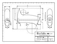
<strong>Pantograph</strong> <strong>07K06.01</strong><br />
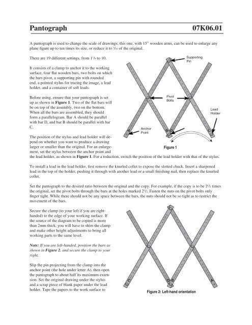
A pantograph is used to change the scale of drawings; this one, with 15” wooden arms, can be used to enlarge any<br />
plane figure up to ten times its size, or reduce it to 1 /10 of the original.<br />
There are 19 different settings, from 1 1 /9 to 10.<br />
It consists of a clamp to anchor it to the working<br />
surface, four flat wooden bars, two bolts on which<br />
the bars pivot, a supporting pin with rounded<br />
end, a pointed stylus for tracing the image, a lead<br />
holder, and a container of soft leads.<br />
Supporting<br />
Pin<br />
Before using, ensure that your pantograph is set<br />
up as shown in Figure 1. Two of the flat bars will<br />
be on top of the assembly, two on the bottom.<br />
When all the bars are assembled, they should<br />
form a parallelogram. Bar A should be parallel<br />
with bar D, and bar B should be parallel with bar<br />
C.<br />
The position of the stylus and lead holder will depend<br />
on whether you want to produce a drawing<br />
larger or smaller than the original. For an enlargement,<br />
set the stylus between the anchor point and<br />
Figure 1<br />
the lead holder, as shown in Figure 1. For a reduction, switch the position of the lead holder with that of the stylus.<br />
To install a lead in the lead holder, first remove the knurled collet to expose the slotted chuck. Insert a sharpened<br />
lead in the top of the holder, pushing it through with another lead or a small finishing nail, then replace the knurled<br />
collet.<br />
Set the pantograph to the desired ratio between the original and the copy. For example, if the copy is to be 2 1 /2 times<br />
the original, set the pivot bolts through the bars at the holes marked 2 1 /2. Fasten the nuts on the pivot bolts only<br />
finger tight. While there should not be any space between the bars, the nuts should not be so tight as to restrict the<br />
movement of the bars.<br />
Secure the clamp (to your left if you are righthanded)<br />
to the edge of your working surface. If<br />
the source of the diagram to be copied is more<br />
than 2mm thick, you will have to shim the clamp<br />
and make other height adjustments to bring all<br />
working parts to the same level.<br />
Note: If you are left-handed, position the bars as<br />
shown in Figure 2, and secure the clamp to your<br />
right.<br />
Anchor<br />
Point<br />
Pivot<br />
Bolts<br />
Lead<br />
Holder<br />
Slip the pin projecting from the clamp into the<br />
anchor point (the hole under letter A), then open<br />
the pantograph to about half its maximum extension.<br />
Set the original drawing under the stylus<br />
and a scrap piece of blank paper under the lead<br />
holder. Tape the papers to the work surface to<br />
Figure 2: Left-hand orientation
prevent them shifting as you trace. A test trace will determine if your set-up needs adjustments. Move the stylus across<br />
the original drawing, then from top to bottom, to check that there is enough room to maneuver the stylus without it getting<br />
too close to the clamp and to make sure that the lead holder not only remains on the scrap piece of paper, but that the new<br />
image doesn’t overlap the original drawing. When satisfied with the set-up, tape a fresh sheet of paper in place of the scrap<br />
paper.<br />
To control the pressure of the lead on the paper, hold the lead<br />
holder rather than the stylus as you trace. You can also hold the<br />
stylus with one hand and press gently on the lead holder with a<br />
finger on your other hand, as shown in Figure 3. To copy long<br />
straight lines you need only mark the end points on your copy,<br />
then join the marks with a ruler later.<br />
If the ratio you require is not marked on the bars, a little planning<br />
and mathematics may be necessary. Suppose, for example,<br />
that you wish to enlarge something 9 times its original size.<br />
While there are no holes marked 9 on the bars, you can enlarge<br />
a drawing 9 times by doing a two-stage enlargement. Set the<br />
pivot bolts through the bars at the holes marked 3 and trace the<br />
original drawing. Place the enlarged image under the stylus and<br />
trace it to obtain an enlargement 9 times the original.<br />
Figure 3<br />
Another example might be to enlarge a 3 /4Й picture to 8Й, a ratio of 10 2 /3. An enlargement of 4 /3 first (which is on the bar as<br />
1 1 /3) would get you to a 1Й copy, then enlarging that copy by 8 would get to the required size of 8Й.<br />
т<br />
www.leevalley.com<br />
1090 Morrison Drive<br />
Ottawa, Ontario<br />
K2H 1C2 Canada<br />
1-800-267-8761<br />
© <strong>Lee</strong> <strong>Valley</strong> <strong>Tools</strong> Ltd. 2008 customerservice@leevalley.com<br />
814 Proctor Avenue<br />
Ogdensburg, New York<br />
13669-2205 USA<br />
1-800-267-8735<br />
Printed in Canada.