Scientech S310 Manual - Artisan Scientific
Scientech S310 Manual - Artisan Scientific
Scientech S310 Manual - Artisan Scientific

Create successful ePaper yourself
Turn your PDF publications into a flip-book with our unique Google optimized e-Paper software.
<strong>Artisan</strong> Technology Group is your source for quality<br />
new and certified-used/pre-owned equipment<br />
• FAST SHIPPING AND<br />
DELIVERY<br />
• TENS OF THOUSANDS OF<br />
IN-STOCK ITEMS<br />
• EQUIPMENT DEMOS<br />
• HUNDREDS OF<br />
MANUFACTURERS<br />
SUPPORTED<br />
• LEASING/MONTHLY<br />
RENTALS<br />
• ITAR CERTIFIED<br />
SECURE ASSET SOLUTIONS<br />
SERVICE CENTER REPAIRS<br />
Experienced engineers and technicians on staff<br />
at our full-service, in-house repair center<br />
SM<br />
InstraView REMOTE INSPECTION<br />
Remotely inspect equipment before purchasing with<br />
our interactive website at www.instraview.com<br />
Contact us: (888) 88-SOURCE | sales@artisantg.com | www.artisantg.com<br />
WE BUY USED EQUIPMENT<br />
Sell your excess, underutilized, and idle used equipment<br />
We also offer credit for buy-backs and trade-ins<br />
www.artisantg.com/WeBuyEquipment<br />
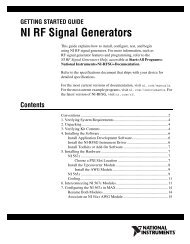
LOOKING FOR MORE INFORMATION<br />
Visit us on the web at www.artisantg.com for more<br />
information on price quotations, drivers, technical<br />
specifications, manuals, and documentation
Models <strong>S310</strong> & <strong>S310</strong>D<br />
Laser Power and Energy<br />
Meters<br />
Setup and Operating<br />
Procedures<br />
Serial Number___________________<br />
P/N 10190H<br />
5205<br />
<strong>Artisan</strong> Technology Group - Quality Instrumentation ... Guaranteed | (888) 88-SOURCE | www.artisantg.com
DETECTOR CALIBRATION DATA<br />
Calorimeter # 1:<br />
Model No:<br />
___________<br />
Serial No:<br />
___________<br />
Calibration Wavelength ___________nm or µm<br />
Output Sensitivity (S): ___________V/W<br />
Time Constant (1/e): ___________sec.<br />
Calibration Temp: ___________°C<br />
Sub. Heater Resistance (R c ): ___________ohms<br />
Sub. Heater Voltage (V h ): ___________volts<br />
Sub. Heater Wattage (W h ) ___________watts<br />
Calorimeter # 2:<br />
Model No:<br />
____________<br />
Serial No:<br />
Calibration Wavelength: nm or µm<br />
Output Sensitivity (S):<br />
V/W<br />
Time Constant (1/e):<br />
sec.<br />
Calibration Temp: °C<br />
Sub. Heater Resistance (R c ):<br />
ohms<br />
Sub. Heater Voltage (V h ):<br />
volts<br />
Sub. Heater Wattage (W h ):<br />
watts<br />
Pyroelectric Detector # 1:<br />
Model No:<br />
Serial No:<br />
Calibration Wavelength: nm or µm<br />
Output Sensitivity:<br />
V/J or __________V/mJ S_________<br />
I__________ L_________<br />
Calibration Temp: °C<br />
Pyroelectric Detector # 2:<br />
Model No:<br />
Serial No:<br />
Calibration Wavelength: nm or µm<br />
Output Sensitivity:<br />
V/J or __________V/mJ S_________<br />
I_________ L__________<br />
Calibration Temp: °C<br />
<strong>Artisan</strong> Technology Group - Quality Instrumentation ... Guaranteed | (888) 88-SOURCE | www.artisantg.com
<strong>Artisan</strong> Technology Group - Quality Instrumentation ... Guaranteed | (888) 88-SOURCE | www.artisantg.com
Thank you for choosing a <strong>Scientech</strong> laser power and energy meter. <strong>Scientech</strong>, an ISO 9000<br />
registered company, and employees are pleased to provide you with a product designed for<br />
years of reliable service. Please read this manual completely before using your<br />
indicator. This information will enable you to fully utilize the equipment and should be<br />
located nearby for reference. The indicator is intended to be used only in the manner<br />
outlined in this manual. Misuse of the equipment may cause product failure.<br />
Note: The Models <strong>S310</strong> and <strong>S310</strong>D are identical to each other in every respect except the<br />
analog meter. The <strong>S310</strong> has both an analog and digital display. The <strong>S310</strong>D has only a<br />
digital readout. All references to the <strong>S310</strong> are intended to include the <strong>S310</strong>D except<br />
where noted. Also the words "indicator" and "meter" are synonymous.<br />
TABLE OF CONTENTS<br />
Astral Calorimeter Specifications ............................................................ 1<br />
Vector Pyroelectric Detector Specifications ................................................... 2<br />
Ultra Calorimeter Specifications .............................................................. 3<br />
Model <strong>S310</strong> Specifications ......................................................................... 4<br />
Environmental Requirements ........................................................................ 5<br />
Unpacking and Setup ............................................................................... 5<br />
Analog Needle Zero Adjust (<strong>S310</strong> only) ........................................................ 5<br />
Connecting Detectors .......................................................................... 5<br />
Turn On Sequence .............................................................................. 6<br />
Front Panel Controls .............................................................................. 6<br />
Count Up (Range) Count Down (Mode) ............................................................ 6<br />
Setup ......................................................................................... 6<br />
Group Configuration for Astral Calorimeters ............................................ 7<br />
Group Configuration for Vector Pyroelectric Detectors .................................. 8<br />
Group Configuration of Ultra Series 150 Watt Detectors ................................ 9<br />
Range ........................................................................................ 11<br />
Mode ......................................................................................... 11<br />
Stats ........................................................................................ 11<br />
Select ....................................................................................... 12<br />
Cancel ....................................................................................... 12<br />
Operating Procedures ............................................................................. 13<br />
USING THE <strong>S310</strong> WITH VECTOR PYROELECTRIC DETECTORS ................................................... 13<br />
Energy Mode............................................................................. 13<br />
Average Energy Mode..................................................................... 14<br />
Average Power Mode...................................................................... 14<br />
Statistics Mode......................................................................... 14<br />
External Trigger........................................................................ 14<br />
Pyroelectric Detector Operation With Oscilloscope....................................... 15<br />
HR Battery Installation................................................................. 15<br />
Set Electrical Time Constants for Model PHF02, PHF05 and PHF09.......................... 16<br />
USING THE <strong>S310</strong> WITH ASTRAL SERIES CALORIMETERS ...................................................... 16<br />
Energy Mode (J)......................................................................... 16<br />
Power Mode (W).......................................................................... 17<br />
Statistics Mode......................................................................... 17<br />
USING THE <strong>S310</strong> WITH ULTRA SERIES DETECTORS ......................................................... 17<br />
Analog Output........................................................................... 17<br />
Determination of Power and Energy from the Analog Output Assuming 3 V Full Scale........ 18<br />
Calorimeter Operation ............................................................................ 21<br />
Calibration Using Electric Substitution Heating .............................................. 21<br />
Operation of Astral Calorimeters with a Digital Volt Meter ................................... 21<br />
Operation of Astral Calorimeters with an Analog Chart Recorder ............................... 22<br />
Damage Considerations ........................................................................ 24<br />
Remote Interface Language ........................................................................ 26<br />
Remote Interface Language Syntax ............................................................. 26<br />
Remote Interface Language Common Commands and Queries ....................................... 26<br />
IEEE488 Specific Commands............................................................... 31<br />
Factory Recalibration ............................................................................ 32<br />
Limited Warranty ................................................................................. 32<br />
Returned Goods Procedure ......................................................................... 32<br />
Schematics ....................................................................................... 33<br />
<strong>Artisan</strong> Technology Group - Quality Instrumentation ... Guaranteed | (888) 88-SOURCE | www.artisantg.com
1<br />
ASTRAL CALORIMETER SPECIFICATIONS<br />
M odel A C 2500 A C 25H D A C X 25H D A C 2501 A C X 2501 A C 25U V A C 2504<br />
Type A bsorber Surface Surface Surface V olum e V olum e V olum e V olum e<br />
Max Beam Diam eter 25 m m 25 mm 8 m m 25 mm 8 m m 25 mm 25 mm<br />
SpectralR esponse .25-35 µm .19-12 µm .4-2 µm .266-1.2 µm .4-1.2 µm .19-.36 µm .85-4.2 µm<br />
A verage Pow er (m ax)<br />
10 W<br />
A verage Pow er (m in)*<br />
1 mW<br />
Noise Level 10 µW or µJ<br />
Pow er Density (m ax) 200 W /cm ² 1.5 kW /cm ² 12 kW /cm ² N ote 1 Note 2 Note 3 Note 4<br />
Peak Pow er Density (m ax) 1 MW/cm ² 100 MW/cm ² 800 MW/cm ² N ote 5 8.5 GW /cm ² N ote 6 Note 7<br />
Single Pulse Energy (m ax)<br />
10 J<br />
Energy Density (m ax) N ote 8 Note 9 Note 10 N ote 11 N ote 12 N ote 13 N ote 14<br />
Precision < 1%<br />
A ccuracy 3%<br />
R esponse Time<br />
3 sec (if attached to a <strong>Scientech</strong> indicator and indicator is in watts mode)<br />
Dimensions DxL (in.) 3.75 x 2.2 3.75 x 2.2 3.75 x 3.82 3.75 x 2.2 3.75 x 3.82 3.75 x 2.2 3.75 x 2.2<br />
(cm ) 9.53 x 5.6 9.53 x 5.6 9.53 x 9.7 9.53 x 5.6 9.53 x 9.7 9.53 x 5.6 9.53 x 5.6<br />
Weight(lbs) 1.5 1.5 1.7 1.5 1.7 1.5 1.5<br />
(kgs) 0.68 0.68 0.77 0.68 0.77 0.68 0.68<br />
Indicator Compatibility H 310,H 310D ,H 410,H410D,<strong>S310</strong>,<strong>S310</strong>D ,D 200PC ,D200C<br />
M odel A C 5000 A C 50H D A C X 50H D A C 5001 A C X 5001 A C 50U V A C 5004<br />
Type A bsorber Surface Surface Surface V olum e V olum e V olum e V olum e<br />
Max Beam Diam eter 50 m m 50 m m 16 m m 50 m m 16 m m 50 mm 50 mm<br />
SpectralR esponse .25-35 µm .19-12 µm .4-2 µm .266-1.2 µm .4-1.2 µm .19-.36 µm .85-4.2 µm<br />
A verage Pow er (m ax)<br />
30 W<br />
A verage Pow er (m in)<br />
100 mW<br />
Noise Level<br />
1 mW or mJ<br />
Pow er Density (m ax) 200 W /cm ² 1.5 kW /cm ² 12 kW /cm ² N ote 1 Note 2 Note 3 Note 4<br />
Peak Pow er Density (m ax) 1 MW/cm ² 100 MW/cm ² 800 MW/cm ² N ote 5 8.5 GW /cm ² N ote 6 Note 7<br />
Single Pulse Energy (m ax)<br />
30 J<br />
Energy Density (m ax) N ote 8 Note 9 Note 10 N ote 11 N ote 12 N ote 13 N ote 14<br />
Precision < 1%<br />
A ccuracy 3%<br />
R esponse Time<br />
3 sec (if attached to a <strong>Scientech</strong> indicator operating in watts m ode)<br />
Dimensions DxL (in.) 4.75 x 2.3 4.75 x 2.3 4.75 x 3.92 4.75 x 2.3 4.75 x 3.92 4.75 x 2.3 4.75 x 2.3<br />
(cm ) 12.07 x 5.8 12.07 x 5.8 12.07 x 9.96 12.07 x 5.8 12.07 x 9.96 12.07 x 5.8 12.07 x 5.8<br />
Weight(lbs) 2.9 2.9 3.1 2.9 3.1 2.9 2.9<br />
(kgs) 1.3 1.3 1.4 1.3 1.4 1.3 1.3<br />
Indicator Compatibility<br />
H310,H 310D ,H 410,H 410D ,<strong>S310</strong>,<strong>S310</strong>D ,D 200PC ,D200C<br />
*C alorim eter installed in an Isoperibolenclosure<br />
Note 1: A C 2501,A C 5001 30 W /cm 2 @ 1064nm , 23 W /cm 2 @ 532nm , 8.5 W /cm 2 @ 355nm , 175m W /cm 2 @ 266nm<br />
Note 2: A C X 2501,A C X 5001 N ote 1 specs x 8 for 400nm to 1.2um<br />
Note 3: AC25UV,A C 50U V 50 W /cm 2 @ 355nm<br />
Note 4: A C 2504,A C 5004 35W /cm 2 @ 1064nm<br />
Note 5: A C 2501,A C 5001 100G W /cm 2 @ 1064nm , 78G W /cm 2 @ 532nm , 29G W /cm 2 @ 355nm , 580M W /cm 2 @ 266nm<br />
Note 6: AC25UV,A C 50U V For repetitive pulses; 101M W /cm 2 @ 355nm<br />
For single pulses; 305G W /cm 2 @ 355nm<br />
Note 7: A C 2504,A C 5004 125G W /cm 2 @ 1064nm<br />
Note 8: A C 2500,A C 5000 Max J/cm 2 = 1000 x (pulse width) 1/2 to a maximum of 200 J/cm 2 .<br />
Note 9: AC25HD,A C 50H D Max J/cm 2 = 4500 x (pulse width) 1/2 to a maximum of 14 J/cm 2 .<br />
Note 10:ACX25HD,A C X 50H D Max J/cm 2 = 36,000 x (pulse width) 1/2 to a maximum of 42.5 J/cm 2 .<br />
Note 11: A C 2501,A C 5001 For repetitive pulses:4.1 J/cm 2 @ 1064nm , 3.2 J/cm 2 @ 532nm , 1.2 J/cm 2 @ 355nm ,<br />
24m J/cm 2 @ 266nm<br />
Note 12: A C X 2501,A C X 5001<br />
Note 13: AC25UV,A C 50U V<br />
Note 14: A C 2504,A C 5004<br />
For single pulses:8 J/cm 2 @ 1064nm , 6.2 J/cm 2 @ 532nm , 2.3 J/cm 2 @ 355nm ,<br />
46m J/cm 2 @ 266nm<br />
N ote 11 specs x 8 for 400nm to 1.2um<br />
For repetitive pulses; 1.1J/cm 2 @ 355nm<br />
For single pulses; 40J/cm 2 @ 355nm<br />
For repetitive pulses; 4.8J/cm 2 @ 1064nm<br />
For single pulses; 10J/cm 2 @ 1064nm<br />
<strong>Artisan</strong> Technology Group - Quality Instrumentation ... Guaranteed | (888) 88-SOURCE | www.artisantg.com
VECTOR PYROELECTRIC DETECTOR SPECIFICATIONS<br />
M odel PH F 02 PH F 05 PH F 09 P 05 P 09<br />
Active Diam eter 2 mm 5 mm 9 mm 5 mm 9 mm<br />
Voltage Response<br />
3.0 V/mJ0.8 V/mJ<br />
S,I 15 V/mJ 2.5 V/mJ 1 V/mJ<br />
L<br />
0.15 V/mJ0.025 V/m J0.01 V/mJ<br />
ElectricalD ecay Time<br />
2.0 msec2.0 msec<br />
(RC Time Constant)<br />
S<br />
0.05 msec 0.05 msec 0.05 msec<br />
I 0.5 msec 0.5 msec 0.5 msec<br />
L 2.5 msec 2.5 msec 2.5 msec<br />
Noise EquivalentEnergy 15 nJ 35 nJ<br />
S,I 3 nJ 15 nJ 35 nJ<br />
L 150 nJ 750 nJ 3500 nJ<br />
Rep Rate (m ax)<br />
400 pps 200 pps<br />
S 4000 pps 4000 pps 4000 pps<br />
I 400 pps 400 pps 400 pps<br />
L 80 pps 80 pps 80 pps<br />
Pulse Width (m ax)<br />
50 µsec 100 µsec<br />
(For Calibrated Response)<br />
S 5 µsec 5 µsec 5 µsec<br />
I 50 µsec 50 µsec 50 µsec<br />
L 250 µsec 250 µsec 250 µsec<br />
Voltage Output(max.)<br />
4.5 V<br />
A verage Power (max) 1 W 2 W 2 W 2 W 2 W<br />
A ccuracy 7% 7% 7% 5% 5%<br />
Indicator Compatibility <strong>S310</strong>,<strong>S310</strong>D ,D 200PC ,D 200P<br />
Model P 25 PH F 25 PH D 25 PH DX 25 PHDX25UV SP 25 SPHF 25 SPHD 25<br />
Max Beam Diam eter 25 mm 25 mm 25 mm 7 mm 7mm 25 mm 25 mm 25 mm<br />
SpectralR esponse U V to mid-IR .4-2um U V to mid-IR<br />
Average Power(max) 5 W* 5 W* 5 W* 5 W* 5 W* 5 W* 5 W* 5 W*<br />
Noise EquivalentEnergy 4 µJ<br />
Energy Density (max) Note 1 Note 2 Note 3 Note 4 Note 1 Note 2<br />
Accuracy 5% 5% 8% ^ 8% ^ 8% ^ 5% 5% 8% ^<br />
OutputSensitivity 8 V/J 8 V/J 2 V/J 2 V/J 2 V/J 8 V/J 8 V/J 2 V/J<br />
Rep Rate (m ax) 100 pps 400 pps 40 pps 40 pps 40 pps 100 pps 400 pps 40 pps<br />
Pulse Duration (max) 0.2 msec 0.045 msec 0.2 msec 0.2 msec 0.2 msec 0.2 msec 0.045 msec 0.2 msec<br />
Dimensions (in.) 2.4dia.x2.3L 2.4dia.x2.3L 2.4dia.x2.3L 2.4dia.x3.9L 2.4D x3.9L 2.3x2.3x0.62.3x2.3x0.62.3x2.3x0.6<br />
(cm ) 6.1dia.x5.8L 6.1dia.x5.8L 6.1dia.x5.8L 6.1dia.x9.9L 6.1D x9.9L 5.8x5.8x1.45.8x5.8x1.45.8x5.8x1.4<br />
Weight(lbs) 0.9 0.9 0.9 1.1 1.1 0.3 0.3 0.3<br />
(kgs) 0.41 0.41 0.41 0.5 0.5 0.14 0.14 0.14<br />
IndicatorCompatibility<br />
H 310,H310D,H 410,H410D,<strong>S310</strong>,<strong>S310</strong>D,D200PC,D200P<br />
2<br />
Model P 50 PH F 50 PH D 50 PH DX 50 PHDX50UV SP 50 SPHF 50 SPHD 50<br />
Max Beam Diam eter 50 mm 50 mm 50 mm 15 mm 15 mm 50 mm 50 mm 50 mm<br />
SpectralR esponse U V to mid-IR .4-2um U V to mid-IR<br />
Average Power(max) 10 W* 10 W* 10 W* 10 W* 10 W* 10 W* 10 W* 10 W*<br />
Noise EquivalentEnergy<br />
16 µJ<br />
Energy Density (max) Note 1 Note 2 Note 3 Note 4 Note 1 Note 2<br />
Accuracy 5% 5% 8% ^ 8% ^ 8% ^ 5% 5% 8% ^<br />
OutputSensitivity<br />
2 V/J<br />
Rep Rate (m ax) 50 pps 400 pps 20 pps 20 pps 20 pps 50 pps 400 pps 20 pps<br />
Pulse Duration (max) 0.4 msec 0.045 msec 0.4 msec 0.4 msec 0.4 msec 0.4 msec 0.045 msec 0.4 msec<br />
Dimensions (in.) 3.5dia.x2.3L 3.5dia.x2.3L 3.5dia.x2.3L 3.5dia.x3.9L 3.5dia.x3.9L 3x3x0.6 3x3x0.6 3x3x0.6<br />
(cm ) 8.8dia.x5.8L 8.8dia.x5.8L 8.8dia.x5.8L 8.8dia.x9.9L 8.8diax9.9L 7.6x7.6x1.57.6x7.6x1.57.6x7.6x1.5<br />
Weight(lbs) 1.5 1.5 1.5 1.7 1.7 0.4 0.4 0.4<br />
(kgs) 0.68 0.68 0.68 0.77 0.77 0.18 0.18 0.18<br />
IndicatorCompatibility<br />
H 310,H310D,H 410,H410D,<strong>S310</strong>,<strong>S310</strong>D,D200PC,D200P<br />
*Fullillum ination ofthe sensor<br />
^Beam centered on absorber<br />
Note 1: Max J/cm 2 =316 x (pulse width) 1/2<br />
Note 2: HD models Max J/cm 2 = 4500 x (pulse width) 1/2 to a maximum of1.4 J/cm 2 .<br />
Maximum pulse width ofthe pyroelectric detectormustbe observed.<br />
Note 3: HDX m odels Max J/cm 2 = 36,000 x (pulse width) 1/2 to a maximum of12.6 J/cm 2 .<br />
Maximum pulse width ofthe pyroelectric detectormustbe observed.<br />
Note 4: HDXUV models Max J/cm 2 = 18,000 x (pulse width) 1/2 to a maximum of5.6 J/cm 2 .<br />
Maximum pulse width ofthe pyroelectric detectormustbe observed.<br />
<strong>Artisan</strong> Technology Group - Quality Instrumentation ... Guaranteed | (888) 88-SOURCE | www.artisantg.com
3<br />
ULTRA CALORIMETER SPECIFICATIONS<br />
Model UC 150 UC 150HD UC 150HD40 UC 150UV<br />
Type Absorber Surface Surface Surface Volume<br />
Max Beam Size 25 mm dia. 25 mm dia. 40 mm x 40 mm 25 mm dia.<br />
Spectral Response .25-35 µm .19-12 µm .19-12 µm .19-.36 µm<br />
Average Power (max)<br />
150 W<br />
Average Power (min)<br />
10 W<br />
Noise Level<br />
0.1 W<br />
Power Density (max) 200 W/cm² 1.5 kW/cm² 1.5 kW/cm² 50 W/cm²<br />
Peak Power Density (max) 1 MW/cm² 100 MW/cm² 100 MW/cm² 1 GW/cm²<br />
Energy Density (max) 1 J/cm²* 14 J/cm²** 14 J/cm²** 15 J/cm²<br />
Precision < 1%<br />
Accuracy 5%<br />
Response Time<br />
Sensor dependent<br />
Dimensions (in.) 4.9H x 3.4 x 4.0D<br />
(cm) 12.5H x 8.6W x 10.2D<br />
Weight (lbs) 2.7<br />
(kgs) 1.2<br />
Indicator Compatibility<br />
<strong>S310</strong>, <strong>S310</strong>D<br />
*Laser pulse duration of 1 µsec<br />
**Laser pulse duration of 10 µsec<br />
ABSORPTION OF HD ABSORBER vs WAVELENGTH<br />
100<br />
95<br />
90<br />
% ABSORPTION<br />
85<br />
80<br />
75<br />
70<br />
65<br />
CAUTION: SPECULAR REFLECTION<br />
60<br />
55<br />
50<br />
200<br />
210<br />
250<br />
300<br />
305<br />
310<br />
315<br />
325<br />
335<br />
350<br />
355<br />
360<br />
385<br />
400<br />
420<br />
440<br />
450<br />
500<br />
530<br />
545<br />
550<br />
595<br />
600<br />
610<br />
635<br />
650<br />
675<br />
850<br />
1060<br />
1300<br />
1480<br />
2000<br />
2100<br />
10600<br />
WAVELENGH [nm]<br />
NOTE: Please exercise caution when using HD detectors. They exhibit spectral reflection of between<br />
7% and 33%, of the input power, back out of the aperture. Please refer to the preceding bar graph to<br />
determine the reflectance for the wavelength you are measuring. These detectors should be treated as a partial<br />
mirror or any other type of reflective optic and the appropriate caution level observed, especially at the CO 2<br />
wavelength.<br />
<strong>Artisan</strong> Technology Group - Quality Instrumentation ... Guaranteed | (888) 88-SOURCE | www.artisantg.com
MODEL <strong>S310</strong> SPECIFICATIONS<br />
Model <strong>S310</strong> <strong>S310</strong>D<br />
Display 4 digitLCD with selectable 4 digitLCD<br />
analog meter movement<br />
Ranges (W atts & Joules FullScale)<br />
10.00 m (W atts only),100.0 m,1.000,10.00 and AUTO (W atts only)<br />
(W hen connected to 25 mm calorimeter)<br />
Ranges (W atts & Joules FullScale)<br />
300.0 m,3.000,30.00 and AUTO (W atts only)<br />
(W hen connected to 50 mm calorimeter)<br />
Ranges (W atts & Joules FullScale)<br />
3.000 m,30.00 m,300.0 m,3.000,30.00,AUTO<br />
(W hen connected to pyroelectric sensor) W ith HR Detectors > 3.000 µ*,30.00 µ*,300.0 µ ,3.000 m,30.00 m,AUTO<br />
Range (W atts FullScale) 150.0<br />
(W hen connected to Ultra calorimeter)<br />
Maximum Rep.Rate with Calorimeters (Joules Mode)<br />
Calorimeter D ependent(1 pulse every 60 to 90 sec.)<br />
Maximum Rep.Rate for Collecting Data in<br />
750 pps<br />
Statistics Mode with Pyroelectric Sensor<br />
Response Time -W atts Mode<br />
Calorimeter D ependent<br />
(W hen connected to calorimeter) 3 to 10 seconds<br />
Dimensions (H X W X D)(inches) 4.68 X 8.83 X 7.83<br />
(cm ) 11.89 X 22.43 X 19.89<br />
Power Requirem ent 120 Volt,60 Hz ± 10 % or 220 Volt,50 Hz ± 10 %<br />
Operating Tem perature 5° C to 40° C<br />
*Not available in long pulse setting on PHF02, PHF05, and PHF09<br />
CE Mark Certification: All of the detectors listed in this manual have been certified for the european CE<br />
mark except the following:<br />
1. All of the Ultra Series calorimeters: Model UC150, UC150UV, UC150HD, UC150HD40.<br />
2. All of the Vector Series slim profile pyroelectric detectors: Models: SP25, SPHF25, SPHD25,<br />
SP25YAG, SP25UV, SP25AL, SP50, SPHF50, SP50YAG, SP50UV, SP50AL.<br />
4<br />
<strong>Artisan</strong> Technology Group - Quality Instrumentation ... Guaranteed | (888) 88-SOURCE | www.artisantg.com
5<br />
ENVIRONMENTAL REQUIREMENTS<br />
This product is intended for indoor use at altitudes up to 2000 meters, Pollution Degree 2 in accordance with<br />
IEC 664 and transient overvoltages according to Installation Categories (Overvoltage Categories) II. Note that<br />
each of the above detectors will not pass the IEC 801 Publication, Part 3, Radiated Electromagnetic Field<br />
Requirements. The system, meter and detector, is designed to measure radiation within the test's radiation<br />
band. The detectors were held outside the radiated electromagnetic field during this test. It is up to the user<br />
to be aware of RF fields present during measurements and their effects if any on those measurements.<br />
UNPACKING AND SETUP<br />
The meter, detectors, and accessories are shipped in custom packing materials. All packing materials should<br />
be saved for future damage free shipments. Before making any connections, verify that the power (VAC)<br />
requirement shown on the power entry module is compatible with the actual AC power outlet to which the<br />
indicator will be connected. insert into the fuse holder. Plug the fuse holder back into the power entry<br />
module. The power requirement of the instrument is easily changed by removing the fuse holder and<br />
voltage selector which is the center portion of the power entry module. To remove, insert a screwdriver<br />
into the right side of the fuse holder and pry out. Slide the voltage selector out, flip over and re-insert into<br />
the fuse holder. Plug the fuse holder back into the power entry module.<br />
Analog Needle Zero Adjust (<strong>S310</strong> only)<br />
The black slotted button located just below the display allows screwdriver adjustment to set the analog needle<br />
to zero. This adjustment should be made before connecting the detector.<br />
Connecting Detectors<br />
Refer to the following drawing of the <strong>S310</strong> rear panel. A 3 meter mini-DIN type cable with "D" shaped<br />
connectors comes with Astral and Ultra calorimeters. A 3 meter BNC type cable comes with Vector<br />
pyroelectric detectors. The input jacks on the rear panel of the <strong>S310</strong> are labeled "Ultra", "Vector", and<br />
"Astral" for hook up of these three types of detectors. Note: Only one detector should be plugged in at any<br />
time. Note that the flat side of the DIN type cables should be oriented up when plugging in to the <strong>S310</strong>. Also<br />
included with each detector is a 1/2" diameter mounting post for installing the detector to your working<br />
surface. An optional mounting base, <strong>Scientech</strong> Model 301-019, is also available for holding the detector/post<br />
assembly upright. Astral calorimeters are sensitive to all types of thermal input. Due to handling of the<br />
calorimeter during setup and possible environmental temperature differences, thermal gradients may exist in<br />
the calorimeter. Several minutes before usage may be required to allow the calorimeter to reach thermal<br />
equilibrium. Note: When using a 25 mm Astral calororimeter for measuring average power levels below 30<br />
mW and single pulse energy levels below 30 mJ, a <strong>Scientech</strong> Model 36-0203A, Isoperibol Enclosure, is<br />
required. The isoperibol enclosure should not be used at average power levels above 30 mW, and single<br />
pulse energy levels above 100 mJ because unwanted heat build up will occur.<br />
<strong>Artisan</strong> Technology Group - Quality Instrumentation ... Guaranteed | (888) 88-SOURCE | www.artisantg.com
6<br />
<strong>S310</strong> Rear Panel<br />
<strong>S310</strong> Front Panel<br />
Turn On Sequence<br />
The <strong>S310</strong> cycles through a self-calibration sequence whenever it is turned on. The display will show all<br />
segments until completion of the self-calibration period which takes about 25 seconds. At the end of this<br />
sequence the unit will revert to its operational state in its last used configuration.<br />
FRONT PANEL CONTROLS<br />
Count Up (Range) Count Down (Mode)<br />
The RANGE and MODE buttons are used to change the numeric entry in the display when in statistics mode,<br />
average energy mode, and calibration and setup modes. The 4 digit LCD allows numeric entry from .0001 to<br />
9999. The decimal place floats to the right as you hold down the RANGE button to achieve larger values<br />
(less resolution) and to the left as you hold down the MODE button to achieve smaller values (greater<br />
resolution).<br />
Setup<br />
The SETUP button controls the process by which you configure the instrument and later recall the<br />
configuration to be used, viewed, and/or changed. Pushing the CANCEL button at any time will terminate<br />
this process with no changes. The large display will show the current value entered. The range digits will<br />
show a two character mnemonic for the current parameter. Briefly pressing the SELECT button always<br />
advances the configuration to the next step. Holding down the SELECT button places the <strong>S310</strong> in its<br />
<strong>Artisan</strong> Technology Group - Quality Instrumentation ... Guaranteed | (888) 88-SOURCE | www.artisantg.com
7<br />
operational state and implements any changes to the group configuration made up to this point. There are<br />
four setup groups which can be configured and recalled by pressing the SETUP button.<br />
To choose one of four setup groups press the SETUP button. The setup group last used (1, 2, 3, or 4) will<br />
appear in the display. To move to the next group press the SETUP button again. To select a setup group<br />
press the SELECT button when the desired group appears in the display. If the SELECT button is not pushed<br />
within a few seconds, the group number displayed will be activated (return to the current configuration for<br />
operation). The default settings for the groups are 1: Astral Calorimeter, 2: Pyroelectric detector, 3: HR<br />
Pyroelectric detector, 4: Ultra Calorimeter.<br />
To observe each element of the current settings in the group press the SELECT button after each setting. To<br />
change settings, press the SETUP button until the desired setting appears, then press the SELECT button.<br />
Group Configuration for Astral Calorimeters<br />
1. Select the desired setup group to configure by pressing the SETUP button repeatedly until the desired<br />
group number appears then press the SELECT button.<br />
2. Press the SETUP button until the calorimeter annunciator “CAL” appears in the display. Press the<br />
SELECT button to activate the calorimeter configuration program.<br />
3. The "tc" (time constant) annunciator now appears in the display. Press the count up (RANGE) and count<br />
down (MODE) buttons to change the number in the display to match the time constant number listed on<br />
the serial tag of your calorimeter. Press the SELECT button to enter the time constant value to memory.<br />
4. The "SP" (speed) annunciator now appears in the display. Press the count up (RANGE) button to speed up<br />
or count down (MODE) button to slow down the response time of the meter. Press the SELECT button<br />
when the desired number appears in the display. The following settings can be fine tuned to your<br />
preference of speed versus overshoot. We recommend these initial settings:<br />
AC2500, AC25HD, ACX25HD 103.0<br />
AC2501, ACX2501, AC25UV, AC2504 136.0<br />
AC5000, AC50HD, ACX50HD 100.0<br />
AC5001, ACX5001, AC50UV, AC5004 120.0<br />
5. The "Cd" (calorimeter delay) annunciator now appears in the display. The calorimeter delay feature<br />
prohibits the display of energy if a pulse is fired before the entered time (1 to 255 seconds) elapses. The<br />
calorimeter must reach environmental thermal equilibrium before a subsequent pulse is fired or low<br />
energy measurements will occur. To set the time delay between pulses use the count up (RANGE) and<br />
count down buttons (MODE) buttons to enter the time in seconds. Press the SELECT button after the time<br />
has been entered. The following time delays are recommended:<br />
AC2500, AC25HD<br />
AC2501, AC25HD, AC2504<br />
AC5000, AC50HD<br />
AC5001, AC50UV, AC5004<br />
60 seconds<br />
60 seconds<br />
90 seconds<br />
90 seconds<br />
6. The "At" (attenuation) annunciator now appears in the display. If no attenuator is being used in<br />
conjunction with the calorimeter, the attenuation factor in the display must be set at 1.000 since this value<br />
is a display multiplier. Attenuation multipliers from .0001 to 9999 can be entered into the displayed value.<br />
Use the count up (RANGE), count down (MODE) buttons to change the attenuation factor. Press the<br />
SELECT button to enter the attenuation factor to memory.<br />
<strong>Artisan</strong> Technology Group - Quality Instrumentation ... Guaranteed | (888) 88-SOURCE | www.artisantg.com
7. If The <strong>S310</strong> has the optional IEEE488 interface, the REMOTE annunciator will appear along with the<br />
digital interface previously selected; r232 (RS232) or IEEE (IEEE488). Press the SETUP button to toggle<br />
the interface between r232 (RS232) and IEEE (IEEE488). Press the SELECT button when the desired<br />
interface appears in the display.<br />
8. If the optional IEEE488 interface was not installed, the "br" (baud rate) annunciator for setting up the<br />
RS232 interface appears in the display along with the baud rate previously selected. To change the baud<br />
rate press SETUP button until the desired baud rate appears in the display. One of the following baud<br />
rates can be selected: 300, 1200, 2400, 9600, and 19,200. When the preferred baud rate appears in the<br />
display press the SELECT button.<br />
9. The "PA" (parity) annunciator now appears in the display. Press the SETUP button to select none, even,<br />
or odd parity. Press the SELECT button to enter the parity of choice to memory<br />
10. The "HS" (handshake) annunciator now appears in the display. Press the SETUP button until your choice<br />
of none (nOnE), on/off (onoF), or clear to send (CtS) appears in the display. Press the SELECT button<br />
when your choice is displayed to enter the handshake to memory.<br />
11. If IEEE488 has been selected, the "bA" (bus address) annunciator appears with the default bus address.<br />
Bus addresses from 0 to 30 may be selected by pressing the count up (RANGE) count down (MODE)<br />
buttons followed by the SELECT button. Once the remote interface has been setup, the group annunciator<br />
will appear. Press the SELECT button or simply wait a few seconds and the group will automatically be<br />
selected for operation.<br />
Group Configuration for Vector Pyroelectric Detectors<br />
1. Select the desired group to be configured.<br />
2. Press the SETUP button until the "PYro" annunciator appears. Immediately press the SELECT button to<br />
select the pyroelectric detector configuration program. Either the "V/J" annunciator or the "V/mJ"<br />
annunciator and a detector sensitivity number will appear in the display.<br />
3. Press the SETUP button to toggle between the V/J and V/mJ entries. The output sensitivity of the<br />
pyroelectric detector in V/J or V/mJ is listed on the serial tag of your detector. Use the count up<br />
(RANGE) and count down (MODE) buttons to enter the V/J or V/mJ value. Press the SELECT button to<br />
enter the value to memory. Do not push the SELECT button before entering the sensitivity number or the<br />
next setup stage will be entered.<br />
4. The "SP" (speed) annunciator now appears in the display. Press the SETUP button to toggle between bL<br />
(coated black detector) or hF (high frequency) detector. If the detector Model No. includes the letters<br />
“HF”, press the SELECT button when the hF annunciator appears in the display. If the detector surface<br />
is black (does not have the letters “HF” in the Model No.) press the SELECT button when the "bL"<br />
annunciator appears in the display.<br />
5. The "AUTO, SET CAL" annunciators now appear in the display (only if watts mode was selected prior to<br />
group configuration). This is the transfer calibration function. This allows you to adjust the output<br />
sensitivity of the pyroelectric detector while in operation enabling you to match the average power<br />
reading of the <strong>S310</strong> to that of the NIST certified detector. Typically a beam splitter is used with the<br />
detector to be calibrated in one beam path and the NIST certified detector in the other beam path. While<br />
using the <strong>S310</strong> with the detector to be calibrated and the NIST standard in an optical calibration, use the<br />
count up (RANGE), count down (MODE) buttons, which change the V/J or V/mJ settings, to make the<br />
8<br />
<strong>Artisan</strong> Technology Group - Quality Instrumentation ... Guaranteed | (888) 88-SOURCE | www.artisantg.com
9<br />
displayed value of the <strong>S310</strong> power reading the same as the NIST standard. Press the SELECT button<br />
when the readings match.<br />
6. The "At" (attenuation) annunciator now appears in the display. If no attenuator or correction factor is to<br />
be applied to the displayed value, the setting should be 1.000. If a multiplier is to be applied to the<br />
displayed value, use the count up (RANGE), count down (MODE) buttons to enter the multiplier value.<br />
Press the SELECT button to enter the value to memory.<br />
7. The REMOTE annunciator now appears along with the digital interface previously selected; r232 (RS232)<br />
or IEEE (IEEE488). Press the SETUP button to change the interface between r232 (RS232) and IEEE<br />
(IEEE488). Press the SELECT button when the desired interface appears in the display.<br />
8. If RS232 has been selected, the "br" (baud rate) annunciator appears in the display along with the baud<br />
rate previously selected. To change the baud rate press the SETUP button repeatedly until the desired<br />
baud rate appears in the display. One of the following baud rates can be selected: 300, 1200, 2400, 9600,<br />
and 19,200. When the preferred baud rate appears in the display press the SELECT button.<br />
9. The "PA" (parity) annunciator now appears in the display. Press the SETUP button to select none, even,<br />
or odd parity. Press the SELECT button to enter the parity choice to memory<br />
10. The "HS" (handshake) annunciator now appears in the display. Press the SETUP button until your choice<br />
of none (nOnE), on/off (onoF), or clear to send (CtS) appears in the display. Press the SELECT button<br />
when your choice is displayed to enter the handshake to memory.<br />
11. If IEEE488 has been selected, the "bA" (bus address) annunciator appears with the default bus address.<br />
Bus addresses from 0 to 30 may be selected by pressing the count up (RANGE) count down (MODE)<br />
buttons followed by the SELECT button. Once the remote interface has been setup, the group annunciator<br />
will appear. Press the SELECT button or simply wait a few seconds and the group will automatically be<br />
selected for operation.<br />
Group Configuration of Ultra Series 150 Watt Detectors<br />
1. Select the desired group to be configured.<br />
2. Press the SETUP button until the "ULtr" annunciator appears in the display. Immediately press the<br />
SELECT button to select the Ultra detector configuration program. The "SET CAL" (calibration)<br />
annunciator now appears in the display. Press the count up (RANGE) and count down (MODE) buttons to<br />
select the calibration constant (mV/W) value listed on the serial tag of your Ultra detector. Press the<br />
SELECT button to enter the calibration constant value to memory.<br />
3. The "SP" (speed) annunciator now appears in the display. Press the count up (RANGE) button to speed up<br />
or count down (MODE) button to slow down the response time of the meter. Press the SELECT button<br />
when the desired number appears in the display. We recommend initially setting the speed to 0.3. Press<br />
the SELECT button to enter the speed setting to memory.<br />
4. The "At" (attenuation) annunciator now appears in the display. If no attenuator is being used in<br />
conjunction with the detector, the attenuation factor in the display must be set at 1.000 since this value is<br />
a display multiplier. Attenuation multipliers from .0001 to 9999 can be entered into the displayed value.<br />
Use the count up (RANGE), count down (MODE) buttons to change the attenuation factor. Press the<br />
SELECT button to enter the attenuation factor to memory.<br />
<strong>Artisan</strong> Technology Group - Quality Instrumentation ... Guaranteed | (888) 88-SOURCE | www.artisantg.com
10<br />
5. The REMOTE annunciator now appears along with the digital interface previously selected; r232<br />
(RS232) or IEEE (IEEE488). Press the SETUP button to change the interface between r232 (RS232) and<br />
IEEE (IEEE488). Press the SELECT button when the desired interface appears in the display.<br />
6. If RS232 has been selected, the "br" (baud rate) annunciator appears in the display along with the baud<br />
rate previously selected. To change the baud rate press SETUP button until the desired baud rate appears<br />
in the display. One of the following baud rates can be selected: 300, 1200, 2400, 9600, and 19,200.<br />
When the preferred baud rate appears in the display press the SELECT button.<br />
7. The "PA" (parity) annunciator now appears in the display. Press the SETUP button to select none, even,<br />
or odd parity. Press the SELECT button to enter the parity choice to memory<br />
8. The "HS" (handshake) annunciator now appears in the display. Press the SETUP button until your choice<br />
of none (nOnE), on/off (onoF), or clear to send (CtS) appears in the display. Press the SELECT button<br />
when your choice is displayed to enter the handshake to memory.<br />
9. If IEEE488 has been selected, the "bA" annunciator appears with the default bus address. Bus addresses<br />
from 0 to 30 may be selected by pressing the count up (RANGE) count down (MODE) buttons followed<br />
by the SELECT button. Once the remote interface has been setup, the group annunciator will appear.<br />
Press the SELECT button or simply wait a few seconds and the group will automatically be selected for<br />
operation.<br />
<strong>Artisan</strong> Technology Group - Quality Instrumentation ... Guaranteed | (888) 88-SOURCE | www.artisantg.com
11<br />
Range<br />
The RANGE button is used to select the range most appropriate for the power or energy level to be measured.<br />
On the <strong>S310</strong> only, held down the RANGE button to toggle the analog meter on or off. The appropriate ranges<br />
will be automatically determined by the type of detector which has been programmed into the group which<br />
has been selected.<br />
1. Press the range button each time to move to the next range. Not pushing the RANGE button when the<br />
desired range appears in the display automatically activates the range after a few seconds and returns the<br />
<strong>S310</strong> to its operational state.<br />
2. To turn the analog meter on or off, press and hold the RANGE button, then release after the meter appears<br />
or disappears (<strong>S310</strong> only).<br />
Mode<br />
The MODE button allows selection of the type of measurement to be made and units of measure to be<br />
displayed; scientific notation or µ, m annunciators. The different measurement modes available are:<br />
When configured for a pyroelectric detector: Energy (J), Avg. Energy (AVG J), Power (W), and Volts (V).<br />
When configured for a calorimeter: Power (W), Energy (J).<br />
When configured for Ultra detector: Power (W) only.<br />
1. Briefly press the MODE button each time a different mode setting is wanted. Not pushing the MODE<br />
button when the desired mode appears in the display automatically activates that mode after a few<br />
seconds and returns the <strong>S310</strong> to its operational state.<br />
2. To select scientific notation or µ and m annunciators, press and hold the MODE button and release when<br />
the desired configuration appears.<br />
Stats<br />
Note: When using the PHF09 pyroelectric detector in the long pulse setting, a manual range must be<br />
selected when running statistics. The STATS button provides statistical analysis of a series of energy<br />
readings (pulses). The average energy, minimum energy, maximum energy, standard deviation, and<br />
coefficient of variation are automatically calculated after each run. Runs of up to 1000 pulses (pulse<br />
population) can be entered.<br />
1. To enter into statistics mode press the STATS button. If you are using a pyroelectric detector, the joules<br />
mode and range selected prior to statistics mode are automatically activated. The pulse population<br />
previously selected along with the STATS annunciator and flashing SET annunciator appear in the<br />
display.<br />
2. Press the count up (RANGE) and/or count down (MODE) buttons to change the display to the desired<br />
number of energy readings to be collected. You may select up to 1000 energy measurements for the pulse<br />
population. Press the SELECT button to enter the pulse population to memory. The "STATS"<br />
annunciator will flash indicating the <strong>S310</strong> is ready to start a new run.<br />
3. Press the SELECT button to begin collecting new data. The <strong>S310</strong> will automatically stop when the pulse<br />
population has been collected.<br />
<strong>Artisan</strong> Technology Group - Quality Instrumentation ... Guaranteed | (888) 88-SOURCE | www.artisantg.com
12<br />
4. The STATS button must be pressed to recall each data point: the number of pulses collected, the<br />
average energy (AVG), minimum energy (MIN), maximum energy (MAX), standard deviation (SIGMA),<br />
and coefficient of variation (CV%). After recalling the data, the flashing STATS annunciator indicates<br />
the <strong>S310</strong> is ready for a new run.<br />
5. Press the SELECT button to begin a new run, or the CANCEL button to exit statistics mode.<br />
Each time a new run begins, data from the previous run is lost. If statistical data is to be automatically<br />
registered, it must be done so through the digital interface.<br />
Select<br />
The SELECT button activates a particular mode or function. Holding down the SELECT button will revert<br />
the <strong>S310</strong> to its operational state during group setup. Any changes made during group setup prior to holding<br />
down the SELECT button will be implemented.<br />
Cancel<br />
The CANCEL button reverts the <strong>S310</strong> to its operational state during group setup. Any changes made during<br />
group setup prior to pressing the CANCEL button will not be implemented. Pressing the CANCEL button<br />
is the exit out of statistics mode and also is used to zero the display when using a calorimeter in watts<br />
mode.<br />
<strong>Artisan</strong> Technology Group - Quality Instrumentation ... Guaranteed | (888) 88-SOURCE | www.artisantg.com
13<br />
OPERATING PROCEDURES<br />
USING THE <strong>S310</strong> WITH VECTOR PYROELECTRIC DETECTORS<br />
Pyroelectric detector models P25, P50, SP25, SP50, P05, and P09 are coated with a special black absorbing<br />
material which provides a very flat spectral response over a broad wavelength band. Models PHF25, PHF50,<br />
SPHF25, SPHF50, PHF02, PHF05, and PHF09 have a partially absorbing, partially reflecting chromium<br />
coating. The relative spectral responses of these detectors are given below.<br />
RELATIVE SPECTRAL RESPONSE<br />
100<br />
HR-P<br />
PERCENT ABSORPTION<br />
90<br />
80<br />
70<br />
60<br />
50<br />
40<br />
30<br />
PHDXUV<br />
PHD, PHDX*<br />
and SPHD<br />
PHF and SPHF<br />
X<br />
P and SP<br />
HR-PHF<br />
20<br />
0.1 1 10 100<br />
*HDX Limited to 0.4 to 2.0 microns<br />
WAVELENGTH [microns]<br />
Before using your Vector joulemeter system, please review the energy density formulas given in the chart on<br />
page 2. Familiarize yourself with all of the specifications of the detector models which you are using. A<br />
damage test slide is provided with each P and PHF type detectors, but not with HD type detectors. Fire the<br />
beam at the test slide before using the detector to be sure you are operating under safe conditions.<br />
Configure One of the Four Groups for the Pyroelectric Detector to be Used (See Page 7).<br />
Energy Mode<br />
Press the MODE button (repeatedly, if need be) until the “J” annunciator appears in the display. Press the<br />
SELECT button or simply wait a few seconds and the joules mode will automatically be activated. Press the<br />
range button (repeatedly, if need be) to select desired range. AUTO range may be selected if the energy<br />
levels of repetitive pulses are to be measured. However, do not select AUTO range if you want to measure<br />
single pulse energy or pulses running at repetition rates lower than 10 Hz.<br />
The energy level of the laser pulses will be displayed on the front panel LCD. The update rate of the display<br />
is 20 Hz. Statistics mode can collect data at repetition rates of up to 300 Hz.<br />
<strong>Artisan</strong> Technology Group - Quality Instrumentation ... Guaranteed | (888) 88-SOURCE | www.artisantg.com
Average Energy Mode<br />
14<br />
The average energy mode displays a running average of a selected number of pulses from 2 to 9999. Enter<br />
into the average energy mode by pressing the MODE button until the “J AVG” annunciator appears in the<br />
display. Press the SELECT button or simply wait a few seconds and the range in the display will<br />
automatically be activated. The number of pulses to be averaged will appear in the display. To change the<br />
number, press the RANGE (count up) and/or MODE (count down) buttons. When the desired number of<br />
pulses to be averaged appears in the display, press the SELECT button. The maximum repetition rate is 300<br />
Hz.<br />
Average Power Mode<br />
The average power mode displays the average power (watts) of repetitively pulsed lasers (minimum rep rate<br />
of 10 pps). Select the appropriate range for the average power level to be measured. To enter into the<br />
average power mode press the MODE button repeatedly until the “W AVG” annunciator appears. Press the<br />
SELECT button or simply wait a few seconds and the <strong>S310</strong> will automatically enter into its operational state<br />
in the average power mode. The maximum repetition rate is 300 Hz<br />
Statistics Mode<br />
The statistics mode will collect data on a pulse population of up to 1000 pulses. At your prompting, the<br />
indicator will display the number of pulses delivered, average energy, minimum energy, maximum energy,<br />
standard deviation, and coefficient of variation. When the statistics mode is selected, the energy mode is<br />
automatically activated regardless of the mode previously selected. Select the appropriate range for the pulse<br />
energy level to be measured. If you select AUTO range, the first few pulses of a run may be missed (not<br />
counted) if the <strong>S310</strong> has to internally change ranges. Therefore, if you want the first pulse to be counted, do<br />
not select AUTO range. It is very important to select the most appropriate range. If you have selected a<br />
manual range and the laser pulse(s) has overflowed the maximum energy of the range, OF will be displayed<br />
when the data is recalled. You should then select a higher range.<br />
To enter into the statistics mode press the STATS button. The number of pulses in the last run will appear in<br />
the display. Use the RANGE (count up) and MODE (count down) buttons to change the display to the desired<br />
number of pulses (up to 1000). Press the SELECT button to enter the pulse population to memory. Press the<br />
SELECT button to begin the run. The indicator will automatically stop once the data has been collected.<br />
Pressing the STATS button recalls the data to the display. The STATS button must be pressed for each event.<br />
Once all of the data has been recalled, pressing the SELECT button starts a new run. Pressing the CANCEL<br />
button returns the indicator to the mode of operation in effect prior to statistics mode.<br />
External Trigger<br />
The automatic trigger threshold of the <strong>S310</strong> is 7 % of full scale. Energy values below 7% of full scale on any<br />
range will not be displayed unless an external trigger is used. The external trigger input is located on the rear<br />
panel of the <strong>S310</strong>. The external trigger pulse needs to have the following characteristics:<br />
1. 2.5 volts min. to 5 volts max.<br />
2. A minimum pulse width of 10 µsec. to a maximum of the laser pulse repetition rate.<br />
3. A maximum rise/fall time of 500 nsec.<br />
The trigger is generated on the rising edge of the incoming pulse.<br />
<strong>Artisan</strong> Technology Group - Quality Instrumentation ... Guaranteed | (888) 88-SOURCE | www.artisantg.com
15<br />
Viable external triggers:<br />
The following pulses will not trigger the <strong>S310</strong>:<br />
A laser pulse must be delivered 1 to 3 msec. (depending on the detector type) after an external<br />
trigger occurs or the meter will reset.<br />
Pyroelectric Detector Operation With Oscilloscope<br />
The pyroelectric detectors may be connected directly to a 1 MΩ input oscilloscope or a 50 ohm input if the<br />
detectors are the HR type (PHF02, PHF05, PHF09, P05 or P09). The peak voltage of the detector divided by<br />
the V/J or V/mJ output sensitivity = energy (joules or millijoules).<br />
HR Battery Installation<br />
A 9 volt alkaline battery comes installed with all HR Series detectors. Always select the OFF position of the<br />
power switch when the detector is not in use to spare the lifetime of the battery. Replace the battery when the<br />
low battery LED indicator lights up.<br />
Remove the two slotted 4-40 binder head screws located on the underside of the detector. Pull off the outer<br />
housing to expose the battery. Remove the used battery from the battery holder and snap in the new battery.<br />
Slide the outer housing back in to place and secure with the screws.<br />
<strong>Artisan</strong> Technology Group - Quality Instrumentation ... Guaranteed | (888) 88-SOURCE | www.artisantg.com
16<br />
Battery Installation<br />
Do not touch the delicate pyroelectric crystals in the HR Series detectors. They should only be cleaned with<br />
a stream of clean air; nitrogen or CO 2 .<br />
Set Electrical Time Constants for Model PHF02, PHF05 and PHF09<br />
The range switch located on the rear of the PHF02, PHF05, and PHF09 detectors selects one of three<br />
electrical time constants and should be set as follows:<br />
S (Short Pulses):<br />
Select for pulse durations of 5 µsec. or less. Repetition rates up to 4 kHZ<br />
can be measured.<br />
I (Intermediate Pulses): Select for pulse durations of 50 µsec. or less. Repetition rates of up to 400<br />
HZ can be measured.<br />
L (Long Pulses): Select for pulse durations of 250 µsec. or less. Repetition rates of up to 80<br />
HZ can be measured.<br />
There are no range settings on the P05 and P09 detectors which utilize a highly absorbing material on the<br />
crystal. The pulse duration considerations merely function in the determination of damage thresholds.<br />
Repetition rates up to 100 HZ using the P05 and 50 HZ using the P09 can be measured.<br />
USING THE <strong>S310</strong> WITH ASTRAL SERIES CALORIMETERS<br />
Be sure the calorimeter is appropriate for the laser measurements you intend on making. Please familiarize<br />
yourself with the operating specifications which are given on page 1 of this manual.<br />
Configure One of the Four Groups for the Astral Calorimeter to be Used (See Page 6) .<br />
Energy Mode (J)<br />
Press the RANGE button to select the desired range. Note: AUTO range does not exist in energy mode. You<br />
must select a manual range. Press the MODE button until the “J” annunciator appears in the display. Press<br />
<strong>Artisan</strong> Technology Group - Quality Instrumentation ... Guaranteed | (888) 88-SOURCE | www.artisantg.com
17<br />
the SELECT button or simply wait a few seconds and the energy mode will automatically be selected. The<br />
system is now ready to measure the energy level of individual pulses.<br />
With the calorimeter delay entered, the <strong>S310</strong> will display the "trig" annunciator and the single pulse energy<br />
after the first pulse is delivered. The "trig" annunciator will then disappear after the calorimeter delay time<br />
has elapsed prompting you to fire another pulse. Do not fire another pulse until the annunciator disappears. If<br />
you do, the <strong>S310</strong> resets the time delay and ignores the sequential pulse altogether.<br />
Power Mode (W)<br />
The speed-up circuit (differentiator) in watts mode is controlled by software and must be adjusted to<br />
accommodate the type of calorimeter being used. The response time is adjusted in the group configuration as<br />
described in the SETUP section above (see page 5). The speed-up circuit is not active in AUTO range.<br />
Press the RANGE button to select the desired range. Select the watts mode by pressing the MODE button<br />
repeatedly until the “W AVG” annunciator appears. The system is now ready to measure the power of a<br />
repetitively pulsed or CW laser.<br />
Statistics Mode<br />
The statistics mode will collect data on a pulse population of up to 1000 pulses. At your prompting, the<br />
indicator will display number of pulses delivered, average energy, minimum energy, maximum energy,<br />
standard deviation, and coefficient of variation. See STATS section for details.<br />
USING THE <strong>S310</strong> WITH ULTRA SERIES DETECTORS<br />
Be sure the Ultra detector is appropriate for the laser measurements you intend on making. Please familiarize<br />
yourself with the operating specifications which are given on page 3 of this manual.<br />
Configure One of the Four Groups for the Ultra Detector to be Used (See Page 8).<br />
The <strong>S310</strong> has only a single range and mode when used with the Ultra detector and is ready to take<br />
measurements once the system has been configured.<br />
The speed up circuit is controlled by software and can be adjusted to your preference - see page 8.<br />
Analog Output<br />
The analog output is an uncalibrated output accessible via the 50 ohm terminated BNC connector located on<br />
the indicator's rear panel. Although the analog output voltage level is uncalibrated, it is representative of the<br />
power and energy readings displayed on the <strong>S310</strong>. The analog output voltage level is approximately 3 volts<br />
full scale. For high accuracy, you must determine the relationship between the analog output voltage level<br />
and the power and energy readings on the <strong>S310</strong> display.<br />
With a calorimeter connected to the <strong>S310</strong> in watts mode, the analog output voltage readings will rise to a<br />
steady level when power is applied to the calorimeter. After the voltage readings become stable, note the<br />
analog output voltage reading and the watt reading on the <strong>S310</strong> display. All subsequent voltage readings will<br />
have the same V/W values. In the joules mode, the voltage will rise to a peak value relatively quickly<br />
(seconds) followed by a rapid return to baseline. The peak voltage is representative of the joules value.<br />
<strong>Artisan</strong> Technology Group - Quality Instrumentation ... Guaranteed | (888) 88-SOURCE | www.artisantg.com
18<br />
Again, this can be determined by noting the peak voltage value on the analog output, and the joules<br />
reading on the <strong>S310</strong> display.<br />
With a pyroelectric detector connected to the <strong>S310</strong>, determine the relationship between the peak voltage value<br />
and the energy (joules) or power (watts) reading on the <strong>S310</strong> display in the same manner.<br />
The analog output with the various detectors and operating modes should appear as follows:<br />
1. Calorimeter Watts Mode<br />
Compare voltage to wattreading displayed on the <strong>S310</strong><br />
to determine V/W constant to use when looking at the<br />
analog output<br />
2. Calorimeter Joules Mode<br />
Compare peak voltage to energy (joules)<br />
reading displayed on the <strong>S310</strong> to determine<br />
V/J constant to use when looking at the analog output.<br />
3. Pyroelectric Watts and Joules Modes<br />
Compare peak voltage to energy (joules) or power<br />
(watts) reading displayed on the <strong>S310</strong> to determine<br />
V/J or V/W constant to use when lookin at the<br />
analog output.<br />
Determination of Power and Energy from the Analog Output Assuming 3 V Full Scale<br />
<strong>Artisan</strong> Technology Group - Quality Instrumentation ... Guaranteed | (888) 88-SOURCE | www.artisantg.com
19<br />
Calorimeters<br />
In the energy (joules) mode the analog output is an amplified voltage signal proportional to the voltage<br />
generated by the calorimeter thermopile. To calculate energy (joules) from the analog output use the following<br />
equation.<br />
J = 0.3(Vpk)(TC)<br />
(S)(R)<br />
where:<br />
Vpk = peak voltage from the analog output<br />
TC<br />
S<br />
R<br />
= the calorimeter time constant from the calorimeter serial tag<br />
= the calorimeter output sensitivity as follows:<br />
0.5 V/W for 25 mm models<br />
0.1667 V/W for 50 mm models<br />
= indicator range multiplier as follows:<br />
10.0 for the 10 or 30 range<br />
100.0 for the 1 or 3 range<br />
1,000.0 for the .1 or .3 range<br />
10,000.0 for the .01 or .03 range<br />
In power (watts) mode, the analog output is nominally 3 V full scale for each range. Therefore, to calculate<br />
watts from the analog output voltage:<br />
W = V/S<br />
where:<br />
V = analog output voltage (V)<br />
S = analog output sensitivity (V/W) ≈ 3 V/range (W)<br />
(for example, on the 10 mW range, S ≈ 3 V/.010 W = 300 V/W)<br />
Pyroelectric Detector<br />
In power (watts) and energy (joules) mode, the peak voltage of a laser pulse is directly proportional to the power<br />
energy level:<br />
W = Vpk/S<br />
where:<br />
Vpk = peak voltage from the analog output<br />
S = analog output sensitivity (V/W) ≈ 3 V/range (W)<br />
(for example, on the 3 mW range, S ≈ 3 V/.003 W = 1000 V/W)<br />
where:<br />
J = Vpk/S<br />
Vpk = peak voltage from the analog output<br />
S = analog output sensitivity (V/J) ≈ 3 V/range (J)<br />
(for example, on the 3 mJ range, S ≈ 3 V/.003 J = 1000 V/J)<br />
Ultra Calorimeter<br />
<strong>Artisan</strong> Technology Group - Quality Instrumentation ... Guaranteed | (888) 88-SOURCE | www.artisantg.com
The analog output voltage is approximately 3 volts full scale. With an Ultra calorimeter the digital display<br />
will read up to 300 watts, even though the Ultra Calorimeter is only rated for 150 watts. To calculate power<br />
from the analog output voltage use the following equation.<br />
20<br />
W= V<br />
[0.0332(S)] - [3 x 10 -5 ]<br />
V = analog output voltage (V)<br />
S = Ultra sensitivity mV/W<br />
<strong>Artisan</strong> Technology Group - Quality Instrumentation ... Guaranteed | (888) 88-SOURCE | www.artisantg.com
21<br />
CALORIMETER OPERATION<br />
Astral calorimeters are powered up by the indicators. To use an Astral calorimeter alone with a volt meter or<br />
chart recorder, you must apply +/-8VDC to the mini DIN connector as shown below.<br />
Calibration Using Electric Substitution Heating<br />
The electric substitution heating option must be ordered and installed at the factory when the calorimeter is<br />
purchased. It can not be retrofitted to a calorimeter at a later time. To calibrate using electric substitution<br />
heating proceed as follows.<br />
1. Remove the screws holding the calorimeter's ID tag and remove the plate to expose the circuit board.<br />
2. Connect the calorimeter to the indicator, turn on the power and let the system equilibrate.<br />
3. Connect a DVM to the test points labeled SUB and HTR on the calorimeter circuit board.<br />
4. Measure the resistance of the substitution heater making sure to subtract the resistance of the patch cables<br />
from the total resistance measurement. Compare this resistance to R c in the calibration data in the front of<br />
the manual. The two should agree within 2%. If not contact <strong>Scientech</strong>.<br />
5. Remove the DVM. Connect a power supply to the SUB and HTR test points and connect the DVM to<br />
monitor the power supply.<br />
6. Set up the indicator in the Watts Mode and the 10W range for 25 mm calorimeters or the 3W range for 50<br />
mm calorimeters.<br />
7. Apply V h volts, stated in the calibration data you received with the calorimeter, to the substitution heater.<br />
8. If needed, adjust the calibration trimpot, R4 on the calorimeter circuit board, until W h Watts, from the<br />
calibration data, is displayed by the indicator.<br />
Operation of Astral Calorimeters with a Digital Volt Meter<br />
The calorimeters may be used with any digital volt meter (DVM) capable of reading 5 volts full scale. The<br />
voltage output of the calorimeter is available on pins 6 and 8 as shown above.<br />
1. Connect the output of the calorimeter to the DVM using the adapter cable.<br />
<strong>Artisan</strong> Technology Group - Quality Instrumentation ... Guaranteed | (888) 88-SOURCE | www.artisantg.com
22<br />
2. Select the DC volts mode.<br />
3. Direct the laser beam on to the absorbing surface of the calorimeter.<br />
4. When the display of the DVM has stabilized (about 2 minutes), calculate the laser power using the<br />
formula: W = V/S<br />
where:<br />
W = Laser power in watts<br />
V = Voltage reading of the DVM in volts<br />
S = Sensitivity of the calorimeter which is 0.5 V/W for 25 mm and 0.167 V/W for the 50 mm calorimeters.<br />
Operation of Astral Calorimeters with an Analog Chart Recorder<br />
Calorimeter Response<br />
The response of a calorimeter to a single pulse input as displayed by a chart recorder appears below.<br />
The output voltage from a chart recorder can be converted to wattage at any time by:<br />
W = V/S, W i = V i /S<br />
V = Chart recorder voltage level in mV<br />
S = Calorimeter sensitivity in mV/W<br />
The total energy (E) in the pulse can be found by integrating the instantaneous wattage over time:<br />
∞<br />
E = ∫ W(t) dt<br />
0<br />
The following methods may be used to compute the total integrated energy:<br />
<strong>Artisan</strong> Technology Group - Quality Instrumentation ... Guaranteed | (888) 88-SOURCE | www.artisantg.com
23<br />
1. Numerical Integration<br />
Finding the area under the curve in figure 7 is the equivalent procedure for determining pulse energy. Choose<br />
an appropriate time interval, dt, and perform the summation:<br />
N<br />
N<br />
E = ∑ W i xdt = (dt/S)∑ V i<br />
I=1 i=1<br />
The error caused by this procedure is:<br />
N<br />
dE = (dt/S) Σ dV i<br />
i=1<br />
The error, in theory, is only dependent upon the value of ∑dV i , that is the cumulative random error of V i . This<br />
number should approach zero if data is carefully taken. The accuracy is also increased if the time interval, dt,<br />
is minimized. Numerical integration can yield accurate results, but is a tedious task.<br />
2. Initial Voltage Interpolation<br />
A method used to eliminate the tedious numerical integration task is to project the thermal decay envelope on<br />
to the voltage axis, determine the 1/e decay time constant T, and estimate the total energy value (E):<br />
E = (V o /S) x T<br />
The change from thermal absorption to thermal transport phenomena near the peak causes difficulty in<br />
accurately projecting the envelope on to the voltage axis introducing an error, dV o . Further, the determination<br />
of the time constant T, introduces another error, dT. The total error is the sum of the two errors.<br />
dE = (V o /S)dT + (T/S)dV o<br />
The difficulty in eliminating the potential error makes this method typically less accurate than numerical<br />
integration, but much faster in application.<br />
3. Peak Voltage Estimate<br />
The peak voltage method requires using an independent determination of total energy and referencing it back<br />
to the peak voltage value, V p .<br />
For a given pulse, use the numerical integration method to obtain E. Note the peak voltage, V p . Compute the<br />
value, F<br />
F = E/V p<br />
For the next pulse compute the total energy:<br />
E = F x V p<br />
The error in using this method yields:<br />
dE = FdV p + V p dF<br />
The accuracy of this measurement depends upon the error in the original calibration, dF, and the error in the<br />
peak voltage dV p . A careful numerical integration yields a value for dF near zero. The value of dV p can be<br />
minimized by maintaining the geometry of the system (i.e. beam intensity, beam profile, wavelength and<br />
environment) during operation to be the same as during calibration. Under controlled circumstances, the<br />
peak method accuracy usually falls between the numerical integration and initial voltage interpolation<br />
methods.<br />
<strong>Artisan</strong> Technology Group - Quality Instrumentation ... Guaranteed | (888) 88-SOURCE | www.artisantg.com
Damage Considerations<br />
24<br />
1. Surface Absorbers<br />
Surface absorbing calorimeters have been found to safely withstand 200 W/cm2. This heat input is diffused<br />
across the thermopile surface so that the local surface temperature is acceptable. Experience has indicated the<br />
damage threshold for a single pulse to be 1 joule/cm2 in a 1 microsecond gaussian pulse. For the<br />
recommended operatings limits please review the energy density formulas given in the chart on page 1.<br />
Heat is produced in the thin pigment layer on the thermopile directly heating the thermopile. Lateral diffusion<br />
of heat across the thermopile is quite effective so that the hot side of the thermopile does not have gross hot<br />
spots. The structure of the thermoelectric junctions is such that each shares the heat flow in parallel and sums<br />
the thermoelectric potential in series. Thus the response is linear with the total heat flow and independent of<br />
heat distribution. The thermopile conductance is about 0.2 watts per degree Celsius and the maximum<br />
recommended power of 10 watts raises the average temperature of the absorbing surface about 50° C above<br />
ambient.<br />
2. Volume Absorbers<br />
See the detector specification chart for maximum pulse energy densities. The surface temperature will rise to<br />
100°C for the briefest instant at these fluency levels. The initial exponential temperature variation with<br />
penetration would rapidly decay as the heat flows through the absorber to the thermopile surface which<br />
remained at ambient temperature during the laser pulse.<br />
If a CW laser beam is being absorbed, a considerably different situation occurs. The continuous supply of<br />
laser power produces steady state temperature distribution from front to back and across the absorber. The<br />
absorption region is small compared to the absorber thickness so the temperature drop is substantially linear<br />
front to back. Because the absorber (glass) is a poor conductor of heat, the same laser power density will<br />
produce a much higher surface temperature than it would produce on the surface absorber. Furthermore, the<br />
glass will confine the heat laterally while the surface absorber does not. The maximum power density for the<br />
volume absorber is nearly one tenth that of the surface absorber.<br />
If a repetitively pulsed laser is supplying a steady power input the situation is even more complicated.<br />
Superimposed upon the average linear temperature drop is the pulse by pulse instantaneous temperature rise.<br />
If we ask how these various parameters of the laser input can vary we obtain a family of curves for the same<br />
glass absorber. (See figures below). For ACX2501, ACX5001 multiply the Power Density and the Energy<br />
Density by 8.<br />
<strong>Artisan</strong> Technology Group - Quality Instrumentation ... Guaranteed | (888) 88-SOURCE | www.artisantg.com
25<br />
The variation of absorptance with wavelength is depicted above. The parameter "a" is the depth of penetration<br />
1/e reduction in laser intensity.<br />
<strong>Artisan</strong> Technology Group - Quality Instrumentation ... Guaranteed | (888) 88-SOURCE | www.artisantg.com
REMOTE INTERFACE LANGUAGE<br />
26<br />
The remote interface language for the <strong>S310</strong> is compatible with Std-IEEE488.2 and it also works with the RS-<br />
232 remote interface.<br />
RS-232 Connector<br />
The RS-232 connector is a 9 pin subminiature connector on the instrument rear panel. The pinout and pin<br />
descriptions are shown below:<br />
1. Unused<br />
2. Data In (RXD)<br />
3. Data Out (TXD)<br />
4. DTR (is generated)<br />
5. Ground<br />
6. DSR (is ignored)<br />
7. RTS (is marking)<br />
8. CTS (is evaluated if requested)<br />
9. Unused<br />
RS-232 Specifications<br />
Type:<br />
EIA-RS232C<br />
Method:<br />
Half-duplex, Asynchronous<br />
Transmission: Bi-directional<br />
Format:<br />
300, 1200, 2400, 9600, 19200 baud rate selectable<br />
Data bits: 7<br />
Parity bit: Even, Odd, or None<br />
Stop bit: 1<br />
Code:<br />
ASCII<br />
Total no. of bits: 10<br />
Remote Interface Language Syntax<br />
Remote interface messages consist of zero or more commands or queries, separated by semicolons and<br />
terminated by a linefeed (IEEE488) or a carriage return (RS232). A command or query consists of a<br />
command or query header followed by zero or more arguments separated by commas. Messages must be less<br />
than 75 characters.<br />
example:<br />
cmd1 arg1;cmd2arg1,arg2;...cmdN arg1<br />
The queries RPT, SND, COL, and *OPC, and the commands COL and *OPC are intended to be placed as<br />
the last command in the message. Placing them elsewhere will not result in harm to the instrument, but it may<br />
produce results which seem unusual.<br />
Queries which have not finished will be aborted by the receipt of additional commands or queries. This will<br />
result in Query Errors in the IEEE488 interface. If a RPT, COL, or SND query is immediately followed<br />
by another command, it is likely that no data will be transmitted. If COL is followed by another command,<br />
statistics gathering will be halted unless the command *WAI appears between the two commands.<br />
Remote Interface Language Common Commands and Queries<br />
<strong>Artisan</strong> Technology Group - Quality Instrumentation ... Guaranteed | (888) 88-SOURCE | www.artisantg.com
27<br />
Most commands and queries may be used with either the RS232 interface or the IEEE488 interface. Some<br />
commands, however, work only with the IEEE488 interface. Some commands require that a password has<br />
been entered. A few commands are archaic, but were left in because no harm was done, and they may be<br />
needed again if multi-channel units are constructed again.<br />
The commands which work in both interfaces are presented first, followed by the password protected<br />
commands peculiar to the IEEE488 interface, followed finally by the archaic commands. In the descriptions<br />
which follow, the command (or query) will be presented first, followed optionally by one or more arguments,<br />
separated by commas. When the vertical bar "|" is used in an argument, it denotes the word "or", and signifies<br />
that one and only one of the items separated by bars may be inserted into the space of the argument. For<br />
example, the command: XXXA|B,C has two arguments, the first of which may be `A' or `B', and the second<br />
of which is the letter `C'. Where a space character is required by the syntax, it is represented with an underline<br />
character.<br />
Commands in this group are available from both interfaces:<br />
*IDN<br />
This query takes no arguments, and returns a comma separated collection of four strings, describing<br />
respectively the manufacturer of the instrument (<strong>Scientech</strong>, Inc.), the model number (<strong>S310</strong>), the serial<br />
number, and the firmware version number.<br />
*SAV_<br />
This is the IEEE488.2 common command for saving the instrument setup. The number may be an integer<br />
from 1 through 4. When used from either remote interface, it saves the current configuration to the numbered<br />
save area. The next time the instrument is powered up or the *RST command is issued with the same save<br />
area as the default, or the RCL command is executed for the same save area, the configuration will be restored<br />
to the values saved.<br />
SENS_PYRO|CAL|PHR|ULTRA<br />
Sets the detector type.<br />
SENS<br />
Returns the detector type (PYRO|CAL|PHR|ULTRA).<br />
RANGE_|auto<br />
Sets the range to the decimal number supplied, or to the closest legal range allowed for the current detector<br />
and configuration. If the word auto is supplied, this command activates the autorange feature if it is supported<br />
for the current detector and configuration.<br />
<strong>Artisan</strong> Technology Group - Quality Instrumentation ... Guaranteed | (888) 88-SOURCE | www.artisantg.com
28<br />
Range Cal 25mm Cal 50mm Ultra Pyro 25/50mm<br />
PHR 2,5,9mm<br />
Long Mode<br />
1 1.000 m 300.0 m 150.0 3.000 m 300.0 u<br />
2 10.00 m 300.0 m 150.0 30.00 m 300.0 u<br />
3 100.0 m 300.0 m 150.0 300.0 m 300.0 u<br />
4 1.000 3.000 150.0 3.000 3.000 m<br />
5 10.00 30.00 150.0 30.00 30.00 m<br />
PHR 2mm PHR 5mm PHR 9mm PHR 5mm PHR 9mm<br />
Range Short/Int Mode Short/Int Mode Short/Int Mode Painted Painted<br />
1 3.000 u 3.000 u 3.000 u 3.000 u 3.000 u<br />
2 30.00 u 30.00 u 30.00 u 30.00 u 30.00 u<br />
3 300.0 u 300.0 u 300.0 u 300.0 u 300.0 u<br />
4 300.0 u 3.000 m 3.000 m 3.000 m 3.000 m<br />
5 300.0 u 3.000 m 30.00 m 3.000 m 30.00 m<br />
RANGE<br />
The RANGE query returns the decimal number between 1 and the maximum range of the instrument. The<br />
meaning of the number varies, depending upon the type of detector, and the configuration of the instrument.<br />
(Generally speaking, there are 5 ranges, though not all of them are used for every detector.)<br />
SND<br />
The SND query causes the instrument to send the next reading to the remote interface.<br />
RPT<br />
This query causes the remote interface to begin sending a sequence of comma-separated readings. A new<br />
reading is sent each time one is taken by the instrument. This activity will continue until the remote interface<br />
is interrupted by a new command or query, or the instrument is turned off.<br />
COL _<br />
This command causes the instrument in energy mode to begin collecting readings for statistical analysis<br />
indicated by the response COLLECTING... This command continues until data points are<br />
collected, or until it is interrupted by another command. If it is interrupted, no statistics are computed. If it<br />
terminates normally, a carriage return and line feed occurs, and it computes values for the mean, max,<br />
standard deviation, and coefficient of variation of the data points collected. Those values may then be<br />
accessed with the queries mean, max, sigma, and cv. The individual data points may be dumped with the<br />
dump query.<br />
MEAN<br />
If statistics have been collected from the front panel, or by the COL or COL commands, this command<br />
returns the mean value of the collection. If no statistics have been collected, it returns to zero.<br />
MIN<br />
If statistics have been collected from the front panel, or by the COL or COL commands, this command<br />
returns the minimum value of the collection. If no statistics have been collected, it returns to zero.<br />
MAX<br />
If statistics have been collected from the front panel, or by the COL or COL commands, this command<br />
returns the maximum value of the collection. If no statistics have been collected, it returns to zero.<br />
<strong>Artisan</strong> Technology Group - Quality Instrumentation ... Guaranteed | (888) 88-SOURCE | www.artisantg.com
29<br />
SIGMA<br />
If statistics have been collected from the front panel, or by the COL or COL commands, this command<br />
returns the standard deviation of the collection. If no statistics have been collected it returns zero.<br />
CV<br />
If statistics have been collected from the front panel, or by the COL or COL commands, this command<br />
returns the coefficient of variation of the collection. If no statistics have been collected it returns zero.<br />
PULSES<br />
Returns the number of pulses collected in the last run.<br />
DUMP<br />
If statistics have been collected from the front panel, or by the COL or COL commands, this command<br />
returns all of the data values in the collection. If no statistics have been collected, it does nothing.<br />
BAUD_<br />
If the takes any of the values 300, 1200, 2400, 9600, or 19200; or any of their abbreviations 3, 12,<br />
24, 96, 192, this command sets the RS232 baud rate to the corresponding value.<br />
PARITY EVEN|ODD|NONE<br />
Sets the parity of the RS232 interface to even parity, odd parity, or no parity, as<br />
specified.<br />
HANDS XON|CTS|NONE<br />
Sets the handshake method of the RS232 interface to XON/XOFF,CTS, or NONE as specified.<br />
IO RS232|IEEE<br />
On units with both IEEE and RS232 interfaces, this command makes the named interface the SAVED active<br />
interface. The next time the instrument is powered up, or its configuration is restored from the configuration<br />
save set active when this command was issued, the specified interface becomes the active remote interface.<br />
*RST<br />
This is the IEEE488.2 common command by the same name. When executed from the RS232 interface, it has<br />
the effect of restoring the saved instrument configuration from the current save area. It has the additional<br />
function in the IEEE488 interface of forcing the interface into the OCIS state and the OQIS state.<br />
METER ON|OFF<br />
Activates or deactivates the analog meter.<br />
MODE VOLTS|ENERGY|AVGE|AVGP<br />
If the specified mode is valid for the detector in use, the software changes mode to the one specified.<br />
MODE<br />
Returns the instrument's operating mode. The possible responses are VOLTS, ENERGY, AVGE, and<br />
AVGP.<br />
*TST<br />
This is the IEEE488.2 common query. From either interface, it causes ROM checksum, and non-destructive<br />
RAM test to be run. If the tests succeed, this query returns zero. If the ROM test fails, a 1 is returned. If the<br />
RAM test fails, a 2 is returned.<br />
*OPC<br />
This is the IEEE488.2 common query. From either interface, it waits until no overlapping command is in<br />
progress, and then it returns a 1.<br />
<strong>Artisan</strong> Technology Group - Quality Instrumentation ... Guaranteed | (888) 88-SOURCE | www.artisantg.com
30<br />
*WAI<br />
This is the IEEE488.2 common command. From either interface, it causes the command processor to wait<br />
until any overlapping command is finished before continuing to process commands.<br />
CLR<br />
This command halts RPT, SND, or COL commands in progress. It also terminates statistics gathering<br />
started by the COL command. This command is issued internally whenever a carriage return that is not<br />
preceded by a command is typed into the RS232 interface. When the IEEE488 interface receives a linefeed<br />
terminated message with no commands, it too generates the CLR command.<br />
*RCL_<br />
This is the IEEE488.2 common command. It takes the single numeric argument [1-4], and restores the<br />
instrument configuration to that configuration stored in the corresponding save area. It also places the IEEE<br />
interface into the OCIS and OQIS states.<br />
COUNT_<br />
Sets the number of pulses making up each average in average energy mode.<br />
COUNT<br />
Returns the number of pulses making up each average in average energy mode.<br />
CALIB_<br />
Sets the calibration constant (Volts/Joule) for a pyro detector, (Volt/Watt) for an Ultra Series detector or the<br />
time constant for a calorimeter. Note: This command is context sensitive, the detector type must be set by the<br />
SENS command before this command is executed.<br />
CALIB<br />
Returns the constant for a pyro detector, or the time constant for a calorimeter. Note: This command is<br />
context sensitive, the returned value depends on the detector type set by the SENS command.<br />
ATTEN_<br />
Sets an attenuation factor for the current detector.<br />
ATTEN<br />
Returns the attenuation factor for the current detector.<br />
ZERO<br />
This command zeros the power baseline for a calorimeter.<br />
PSWD_<br />
Enables password protection commands if the password is entered correctly.<br />
PSPEED HF|BL<br />
Sets the electronic response speed according to the repetition rate capability of the pyroelectric detector type -<br />
a "black" coated absorbing crystal, or uncoated "high frequency" absorbing crystal.<br />
PSPEED<br />
Returns the pyro speed, possible responses are BL and HF.<br />
CSPEED_<br />
<strong>Artisan</strong> Technology Group - Quality Instrumentation ... Guaranteed | (888) 88-SOURCE | www.artisantg.com
31<br />
Sets the watts mode display response speed for calorimeters and Ultra Series detectors.<br />
CSPEED<br />
Returns the watts mode display response speed for calorimeters and Ultra Series detectors.<br />
CDELAY_<br />
Sets the "Calorimeter Delay" function of the meter.<br />
CDELAY<br />
Returns the "Calorimeter Delay" function of the meter.<br />
IEEE488 Specific Commands<br />
These commands may be used only from the IEEE488.2 interface. They are all members of the collection of<br />
the so-called "common Commands" described in the IEEE488.2 standard.<br />
*CLS<br />
Clears the Standard Event Status Register and forces the device into Operation Complete Command Idle<br />
state.<br />
*ESR<br />
Returns a decimal number which is the value of the Standard Event Status Register. Reading the register<br />
clears it.<br />
*ESE_<br />
Sets the bits of the Standard Event Status Enable Register to the binary representation of the decimal integer<br />
supplied.<br />
*ESE<br />
Returns a decimal number representing the contents of the Standard Event Status Enable Register.<br />
*SRE_<br />
Sets the bits of the Standard Request Enable Register to the binary representation of the decimal integer<br />
supplied.<br />
*SRE<br />
Returns a decimal number which represents the contents of the Service Request Enable Register.<br />
*OPC<br />
Sets the "Operation Complete" event bit in the Standard Event Status Enable Register when pending device<br />
operations have been completed.<br />
*STB<br />
Returns a decimal number which is the value of the IEEE488.1 status byte and the Master Summary Status<br />
message.<br />
<strong>Artisan</strong> Technology Group - Quality Instrumentation ... Guaranteed | (888) 88-SOURCE | www.artisantg.com
FACTORY RECALIBRATION<br />
<strong>Scientech</strong> recommends that a complete calibration be performed annually to verify system accuracy. Please<br />
contact our Product Service Department at (800)525-0522 or (303)444-1361 or Fax (303)444-9229 to arrange<br />
for a NIST traceable, factory calibration.<br />
32<br />
LIMITED WARRANTY<br />
All <strong>Scientech</strong> Laser Power and Energy Measurement Systems are warranted against defects in materials and<br />
workmanship for two (2) years from date of delivery. During the warranty period, <strong>Scientech</strong> will repair, or at<br />
its option replace at no charge, components that prove to be defective. The equipment must be returned,<br />
shipping prepaid, to <strong>Scientech</strong>'s product service facility. This limited warranty does not apply if the<br />
equipment is damaged by accident or misuse or as a result of service or modification by other than a<br />
<strong>Scientech</strong> service facility. The foregoing warranty is in lieu of all other warranties expressed or implied<br />
including but not limited to any implied warranty of merchantability, fitness, or adequacy for any special<br />
incidental or consequential damages whether in contract, tort, or otherwise.<br />
RETURNED GOODS PROCEDURE<br />
Should it become necessary to return any item to <strong>Scientech</strong> for any reason, please contact our Product Service<br />
Department at (800)525-0522 or (303)444-1361 or Fax (303)444-9229. When you call, please be ready to<br />
provide model number, serial number, and a description of the problem. Frequently we can provide self-help<br />
information which will eliminate the need for returning the unit(s).<br />
If equipment return is required, please pack the items in the original box and packing material. As an<br />
alternate, place the equipment in a snug-fitting box, then pack that box in a larger box with at least four inches<br />
of packing material. <strong>Scientech</strong> does not assume responsibility for underpacked items.<br />
Please include the name and phone number of the person we should contact regarding repair questions.<br />
Normally, products are repaired and shipped within 5 working days after their arrival at the product service<br />
facility. This is an average time and could vary depending on the workload.<br />
Shipping Address:<br />
<strong>Scientech</strong>, Inc.<br />
Product Service Department<br />
5649 Arapahoe Ave.<br />
Boulder, Colorado 80303<br />
U.S.A.<br />
<strong>Artisan</strong> Technology Group - Quality Instrumentation ... Guaranteed | (888) 88-SOURCE | www.artisantg.com
33<br />
SCHEMATICS<br />
<strong>Artisan</strong> Technology Group - Quality Instrumentation ... Guaranteed | (888) 88-SOURCE | www.artisantg.com
<strong>Artisan</strong> Technology Group - Quality Instrumentation ... Guaranteed | (888) 88-SOURCE | www.artisantg.com<br />
34
<strong>Artisan</strong> Technology Group - Quality Instrumentation ... Guaranteed | (888) 88-SOURCE | www.artisantg.com<br />
35
<strong>Artisan</strong> Technology Group - Quality Instrumentation ... Guaranteed | (888) 88-SOURCE | www.artisantg.com<br />
36
<strong>Artisan</strong> Technology Group - Quality Instrumentation ... Guaranteed | (888) 88-SOURCE | www.artisantg.com<br />
37
<strong>Artisan</strong> Technology Group is your source for quality<br />
new and certified-used/pre-owned equipment<br />
• FAST SHIPPING AND<br />
DELIVERY<br />
• TENS OF THOUSANDS OF<br />
IN-STOCK ITEMS<br />
• EQUIPMENT DEMOS<br />
• HUNDREDS OF<br />
MANUFACTURERS<br />
SUPPORTED<br />
• LEASING/MONTHLY<br />
RENTALS<br />
• ITAR CERTIFIED<br />
SECURE ASSET SOLUTIONS<br />
SERVICE CENTER REPAIRS<br />
Experienced engineers and technicians on staff<br />
at our full-service, in-house repair center<br />
SM<br />
InstraView REMOTE INSPECTION<br />
Remotely inspect equipment before purchasing with<br />
our interactive website at www.instraview.com<br />
Contact us: (888) 88-SOURCE | sales@artisantg.com | www.artisantg.com<br />
WE BUY USED EQUIPMENT<br />
Sell your excess, underutilized, and idle used equipment<br />
We also offer credit for buy-backs and trade-ins<br />
www.artisantg.com/WeBuyEquipment<br />
LOOKING FOR MORE INFORMATION<br />
Visit us on the web at www.artisantg.com for more<br />
information on price quotations, drivers, technical<br />
specifications, manuals, and documentation