User Manual - Q-See
User Manual - Q-See
User Manual - Q-See

Create successful ePaper yourself
Turn your PDF publications into a flip-book with our unique Google optimized e-Paper software.
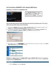
SPOT OUT<br />
The Spot Out feature allows you to send selected video channels to a separate monitor.<br />
Menus and controls will not display in this monitor. If you do not wish to use this feature then<br />
you do not have to attach this port.<br />
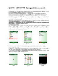
3.2 CONNECTING A PTZ CAMERA<br />
In order to operate a PTZ camera from the QSDT4PCRC, you will need to have first installed<br />
the card into a PCI slot within the computer and attached the video dongle.<br />
You will also need an RS485 to RS232 (Serial) adapter as well as having a serial port on the<br />
back of your PC.<br />
Spot Out with Multiple Cards<br />
In situations where multiple cards are<br />
installed, only one card can provide the signal<br />
to the remote monitor.<br />
Link the con2 to con1 ports on the cards,<br />
with the last card linking to the Spot Out port<br />
on the face plate.<br />
PICTURE 3-4<br />
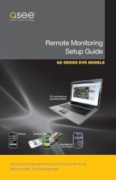
AUDIO<br />
You will only need to install the Audio dongle if you have audio-equipped cameras,<br />
microphones or other audio input devices.<br />
Use of this dongle will take up an additional<br />
I/O port on the computer.<br />
The audio connector’s pins are mapped out<br />
in Picture 3-5.<br />
PIN1 AUDIO-1 PIN2 GND<br />
PIN3 AUDIO-2 PIN4 GND<br />
PIN5 AUDIO-3 PIN6 GND<br />
PIN7 AUDIO-4 PIN8 GND<br />
J5<br />
GiL-G-8P-S3T2-E<br />
1<br />
2<br />
3<br />
4<br />
5<br />
6<br />
7<br />
8<br />
PTZ Camera<br />
RS485 to<br />
Serial Adapter<br />
1<br />
3 4<br />
PICTURE 3-7<br />
PC<br />
STEP 1. Connect the RS485 cables from the PTZ camera to the RS485-to-Serial Adapter<br />
STEP 2. Connect the Adapter to the serial port on the back of the PC<br />
STEP 3. Connect the video line from the camera to any Video In port on the DVR card<br />
(Item 4)<br />
You may now connect your camera to a power source.<br />
2<br />
CHAPTER 3 VIDEO CAPTURE CARD HARDWARE AND CONNECTIONS<br />
VIDEO<br />
The video dongle connects to the 15-pin<br />
receiver on the card. The four video inputs<br />
use BNC connectors to interface with the<br />
camera leads.<br />
Video<br />
Video<br />
Video<br />
Video<br />
Not Used<br />
Not Used<br />
Not Used<br />
Not Used<br />
PICTURE 3-5<br />
1<br />
9<br />
2<br />
10<br />
3<br />
11<br />
4<br />
12<br />
5<br />
13<br />
6<br />
14<br />
7<br />
15<br />
8<br />
Ground<br />
Please see Chapter 8 for instructions on operating the PTZ camera with the SuperDVR<br />
software.<br />
PICTURE 3-6<br />
14 15