Annexes - Marine Accident Investigation Branch
Annexes - Marine Accident Investigation Branch
Annexes - Marine Accident Investigation Branch

Create successful ePaper yourself
Turn your PDF publications into a flip-book with our unique Google optimized e-Paper software.
Survey Report no. 091909<br />
Annex A
The Test House Laboratory Report<br />
Annex B
THE TEST HOUSE (CAMBRIDGE) LTD. JOB AND REPORT REFERENCE: T90996<br />
LABORATORY REPORT<br />
EXAMINATION OF A FRACTURED<br />
AXIAL DISPLACEMENT<br />
HYDRAULIC MOTOR CYLINDER<br />
BLOCK AND ASSOCIATED<br />
ITEMS FROM THE ANCHOR<br />
WINDLASS OF<br />
MT STELLAR VOYAGER<br />
For: <strong>Marine</strong> <strong>Accident</strong> <strong>Investigation</strong> <strong>Branch</strong><br />
Mountbatten House<br />
Grosvenor Square<br />
Southampton<br />
SO15 2JU<br />
This Report Comprises:<br />
Title Page: 1<br />
Text Pages: 1 to 14<br />
Figure Sheets: 1 to 33<br />
Appendices: 1 to 3<br />
UKAS DISCLAIMER<br />
This project includes tests and examinations, some of which were completed against<br />
UKAS accredited procedures. The scope of laboratory accreditation does not, however,<br />
include the analysis of test data or the offering of professional opinions.
LABORATORY REPORT<br />
EXAMINATION OF A FRACTURED AXIAL DISPLACEMENT<br />
HYDRAULIC MOTOR CYLINDER BLOCK AND ASSOCIATED<br />
ITEMS FROM THE ANCHOR WINDLASS OF<br />
MT STELLAR VOYAGER<br />
For: <strong>Marine</strong> <strong>Accident</strong> <strong>Investigation</strong> <strong>Branch</strong><br />
Mountbatten House<br />
Grosvenor Square<br />
Southampton<br />
SO15 2JU<br />
THE TEST HOUSE (CAMBRIDGE) LTD REFERENCE: T90996<br />
RECEIPT DATE: 1 JULY 2009<br />
RECEIPT DATE (CLIENTS INSTRUCTION): 3 JULY 2009<br />
REPORT DATE: 5 August 2009<br />
1. INTRODUCTION AND BACKGROUND<br />
Instructions to examine the fractured hydraulic cylinder block and<br />
associated items were received from <strong>Marine</strong> <strong>Accident</strong> <strong>Investigation</strong><br />
<strong>Branch</strong> (MAIB).<br />
The laboratory was provided with most of the fractured hydraulic motor<br />
cylinder block, parts of its fractured outer casing, the control lense, the<br />
output shaft, shaft roller bearings, planetary gear and a brake plate set.<br />
The hydraulic motor was reported to be from the forward deck mounted<br />
anchor windlass of MT STELLAR VOYAGER, which had failed<br />
catastrophically during operation.<br />
1
The parts were jointly inspected with the Inspector of <strong>Marine</strong> <strong>Accident</strong>s<br />
at the Test House (TTH) on the evening of Friday 3 rd July 2009. During<br />
the examinations, TTH confirmed that it had the necessary laboratory<br />
facilities and staff resource to identify the critical fracture and damage<br />
mechanisms apparent in the failed parts provided. TTH, however,<br />
declared that it had no expertise in hydraulic engineering, and that any<br />
analysis or review of the motor design and hydraulic system would<br />
need to be commissioned from other suitable experts in this field.<br />
Not withstanding the earlier qualification in respect of hydraulic<br />
engineering system and design considerations, objectives of the<br />
laboratory based examinations was firstly to identify the prevailing<br />
fracture types apparent in the parts provided. Then from the<br />
fractographic evidence, the investigation was to establish the type and<br />
direction of the critical damaging fracture stresses or forces. In this<br />
latter regard, the parts of interest were examined in the metallurgical<br />
laboratory of TTH as follows.<br />
2. EXAMINATION OF THE HYDRAULIC MOTORS FRACTURED AND<br />
CLOSELY RELATED PARTS<br />
2.1 Control Lense<br />
2.1.1 Visual Inspection<br />
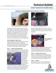
The hydraulic motors control lense appeared free from visually<br />
apparent cracking and damage (Figures 1 and 2). The cylinder block<br />
facing side at the lense (Figure 2) exhibited some service rubbing wear,<br />
none of which, however, appeared significant or material in respect of<br />
the motors failure. No evidence of cracking was apparent in any of the<br />
four inlet and outlet ports.<br />
2.2 Cylinder Block<br />
2
2.2.1 Visual Inspection<br />
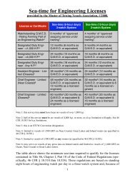
The cylinder block had comprised seven equally spaced cylinder holes<br />
on a pitch circle diameter of approximately 70mm, and a single centre<br />
pin hole. The block had fractured into a number of pieces, of which<br />
four had been recovered for examination (Figures 3, 4 and 5). The<br />
piece or pieces not recovered for examination comprised the outer and<br />
inter wall parts of two adjacent cylinders (Figure 6).<br />
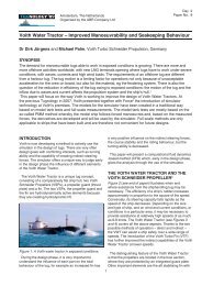
The cylinder blocks control lense mating face exhibited evidence of<br />
light service rubbing wear and what appeared to be extensive post<br />
fracture mechanical impact type damage (Figure 5).<br />
The fractures were consistently oriented in a generally longitudinal<br />
direction. They were located in both the ligaments between the<br />
cylinders and the blocks outer diameter, and at a number of inter<br />
cylinder ligament locations (Figures 7, 8, 9 and 10). The pieces<br />
exhibited evidence of multiple random post fracture impact marks,<br />
which were apparent at both the pieces fracture surfaces and the<br />
blocks outer diameter (Figures 11 and 12). No evidence of precasualty<br />
fatigue type cracking was apparent at any of the fracture<br />
surfaces.<br />
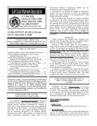
Cylinder holes at the blocks output end exhibited evidence of extensive<br />
secondary radial cracks, which were apparent both at the blocks end<br />
(Figures 13, 14 and 15) and along individual cylinder walls (Figures 16<br />
and 17). The cracking was noted to be at its most severe adjacent to<br />
the fracture sites, and appeared to have resulted from a post yield hoop<br />
stress acting upon the cylinder walls.<br />
A number of the individual cylinder walls at the blocks fractured side<br />
exhibited evidence of piston mechanical indenting damage (Figures 18,<br />
3
19 and 20), which appeared to be consistent with immediately prefracture<br />
yielding and deformation of the respective cylinder bores.<br />
Though not apparently causative or related to the fracture process, a<br />
number of the cylinder bores exhibited evidence of incipient service<br />
wear or spalling type damage (Figure 21).<br />
2.2.2 Detailed Fractographic Examination<br />
Fractured pieces of the cylinder block were cleaned and examined in<br />
detail via both an optical stereo microscope and a Scanning Electron<br />
Microscope (SEM).<br />
The cleaned fracture surfaces were seen to comprise what appeared to<br />
be a coincident series of fast brittle fractures (Figures 22, 23, 24, 25, 26<br />
and 27), as exemplified by the widespread evidence of both brittle and<br />
chevron type fracture markings. Though the fracture surfaces were<br />
seen to exhibit numerous sites of post fracture impact type damage,<br />
the more detailed examination identified no evidence of pre-existing<br />
manufacturing defects or fatigue cracking.<br />
The detailed SEM examination of the cylinder block fracture surfaces<br />
confirmed the fracture mode to be one of brittle transgranular cleavage<br />
(Figures 28, 29 and 30). Examination of the incipient cylinder wall<br />
damage (Figure 31) appeared less definitive (Figure 32) and could<br />
have resulted from either local micro cracking of the hard chromium<br />
plating, or more likely, sliding contact fatigue type surface spalling.<br />
The detailed fractographic examination served to confirm that failure of<br />
the cylinder block had resulted from a single event brittle fracture<br />
process. The examination also served to confirm that the block had<br />
been free from significant manufacturing defects, and similarly that the<br />
block body exhibited no evidence of prior fatigue cracking.<br />
4
2.2.3 Metallographic Examination<br />
A single metallographic specimen was removed from the fracture sites<br />
in one of the detached pieces from the cylinder block (Figure 33). The<br />
specimen was Bakelite mounted and prepared for examination by<br />
conventional metallographic techniques, including final polishing to a 1<br />
micron diamond finish. Examination of the prepared specimen was<br />
subsequently completed in the unetched condition and then again after<br />
etching in Nital.<br />
The prepared specimens included three fracture sites (Figure 34), all of<br />
which exhibited similar features. The fracture sites were accompanied<br />
by extensive evidence of secondary radial cracking of the cylinder walls<br />
(Figures 35 and 36), and the fracture process appeared to be<br />
essentially brittle (Figure 37).<br />
The cylinder bores were seen to have been hard chromium plated, and<br />
near surface regions of the steel block substrate exhibited very<br />
widespread evidence of sub grain strain induced twinning (Figure 38).<br />
Widespread evidence of cracking was also apparent in the chromium<br />
plating (Figure 38), which coupled with the near surface sub grain<br />
strain damage suggested that extensive hoop stress type yielding of<br />
the cylinder bores had occurred immediately prior to the terminal<br />
fracture.<br />
The cylinder blocks microstructure clear of the immediate cylinder bore<br />
regions comprised pearlite colonies in a hyper-fine ferritic matrix,<br />
consistent with that of an engineering type steel that had entered<br />
service in a normalised type condition (Figure 39).<br />
5
2.2.4 Vickers Hardness Test<br />
A Vickers hardness test was completed on the metallographic<br />
specimen after documenting of salient microstructural features, the test<br />
results of which were as follows:<br />
VPN 198, 193, 199 with an average of 197 (HV10)<br />
From the hardness data obtained, an Ultimate Tensile Strength (UTS)<br />
of circa 637 N/mm² was obtained for the block steel via hardness to<br />
tensile strength conversion tables. The estimated tensile strength<br />
accorded well with the microstructural observations.<br />
2.2.5 Tensile Test<br />
A single longitudinal tensile test specimen was removed from the<br />
opposite side of the cylinder block to that of the fracture sites. The test<br />
was completed in accordance with BSEN 10002-1:2001, with a<br />
calculated stressing rate in the pre-yield elastic region of the test of<br />
22.4 N/mm 2 /second (BSEN10002-1:2001 specified stressing rate 6 to<br />
60 N/mm 2 /second) and a total test duration from commencement of<br />
loading to specimen fracture of over 3 minutes. The certified test<br />
results are reproduced in Appendix 1, and the associated<br />
Stress/Engineering Strain and Force/Displacement graphs are shown<br />
in Appendices 2 and 3 respectively.<br />
The tensile test results were free from anomalies and in good<br />
agreement with what could have been predicted from the cylinder<br />
blocks prevailing microstructure and the hardness test results. Clearly,<br />
at tensile test type stressing rates the block steel was seen to exhibit a<br />
significant capacity for post yield ductile plastic deformation; as<br />
evidenced by the reported elongation, reduction of area and the two<br />
graphical Appendices. The block steel was also seen to exhibit a<br />
6
elatively low Yield to UTS ratio, which under most circumstances<br />
should also have facilitated significant capacity for conversion of post<br />
yield stressing into ductile plastic deformation.<br />
The tensile test data clearly formed a sharp contrast with the blocks<br />
apparent service overload performance, which was characterised by<br />
brittle behavior and a near absence of post yield plastic deformation.<br />
The steels apparent absence of embrittlement, as demonstrated by the<br />
tensile test data, and the conflicting service fracture evidence, would<br />
collectively suggest that stressing rate was significant in the service<br />
failure. In turn, this suggested that the apparently brittle fracture of the<br />
cylinder block had resulted from a very rapid or near instantaneous rate<br />
of overloading, and that stressing rate rather than embrittlement of the<br />
steel was the most probable reason fore the apparently brittle service<br />
fracture.<br />
2.3 Hydraulic Motor Pistons<br />
Though the motor had comprised seven pistons and a central pin, only<br />
three pistons had been recovered and presented for laboratory<br />
examination (Figure 40).<br />
2.3.1 Visual Inspection<br />
The three pistons appeared free from primary or significant damage.<br />
One piston was seen to have lost one and a half of its two rings and<br />
some local associated post failure impact damage to the piston crown<br />
end was also apparent (Figure 41). The three pistons also exhibited<br />
signs of incipient service related surface wear or spalling damage<br />
(Figure 42, 43 and 44).<br />
7
2.3.2 Detailed Fractographic Examination<br />
One of the pistons was cleaned, to facilitate examination of the surface<br />
damage via the SEM.<br />
The surface damage, which was apparent at both the pistons main<br />
body and between the two rings (Figures 45, 46, 47 and 48), was<br />
confirmed to have resulted from a common sliding contact fatigue<br />
spalling type mechanism. The detailed examination confirmed that the<br />
spalling resulted from very shallow sub-surface sliding contact fatigue<br />
cracks which had grown upwards to the surface and then coalesced to<br />
result in spalling. In no case had the cracks grown into the piston body,<br />
and the damage was not related to the casualty in any way. Rather,<br />
the damage was attributed to accumulated non-critical service wear.<br />
2.4 Hydraulic Motor Output Shaft<br />
The motors output shaft (Figure 49) comprised a series of eight pin<br />
pockets at one end and a spline type gear drive at its other end. The<br />
shaft also retained the inner raceway cone from the larger of the two<br />
output shaft rolling element type bearings.<br />
2.4.1 Visual Inspection<br />
The shafts pin pockets exhibited evidence of local seizure type damage<br />
and a number of end plate retaining cap-head studs had sheared off<br />
(Figure 50). The shafts gear drive end appeared generally free from<br />
service wear, and the spline damage apparent was thought to post<br />
date failure of the cylinder block (Figure 51). The local seizure damage<br />
at a number of the pin pockets was similarly consistent with post<br />
cylinder body failure type damage, and probably resulted from loss of<br />
8
oil lubrication that would have occurred during failure of the cylinder<br />
block.<br />
In the absence of any primary failure damage the shaft was not<br />
examined further.<br />
2.5 Large (First) Hydraulic Motor Output Shaft Bearing<br />
The inner raceway cone of this bearing was retained on the motors<br />
output shaft (Figure 49). Its rolling surface was in good condition and<br />
totally free from both service and casualty related damage. Only three<br />
of the tapered rollers were recovered, all of which were free from<br />
significant service wear or damage (Figure 52). The outer raceway ring<br />
was similarly free from significant service wear and damage (Figure<br />
53). The roller cage had suffered extensive deformation and tearing<br />
type damage (Figure 54) all of which was thought to represent<br />
consequential type of damage.<br />
In the absence of any primary damage, parts of the bearing were not<br />
examined further.<br />
2.6 Small (Second) Hydraulic Motor Output Shaft Bearing<br />
This second rolling element bearing was received fully assembled<br />
(Figure 55). The bearing was found to turn freely and all the rolling<br />
elements were found to be in good, damage free, serviceable<br />
condition.<br />
In the absence of any visually apparent damage the bearings parts<br />
were not examined further.<br />
9
2.7 Hydraulic Motor Casing<br />
The hydraulic motor casing had suffered a catastrophic fracture event<br />
and its remnants comprised the mounting flange end and twenty four<br />
broken pieces (Figures 56 and 57). All but one of the fractured pieces<br />
exhibited evidence of impact damage and the fracture surfaces<br />
exhibited the typical grey brittle appearance of a grey flake type cast<br />
iron (Figures 58 and 59).<br />
2.7.1 Detailed Fractographic Examination<br />
One fractured piece (Figure 58) was cleaned and examined via the<br />
SEM.<br />
The material was confirmed to be of a grey flake graphite cast iron type<br />
and as one would expect, the fracture process was entirely brittle<br />
(Figure 60).<br />
2.7.2 Metallographic Examination<br />
A single metallographic specimen was removed from a piece of the<br />
fractured casing (Figure 58). The specimen was mounted, prepared<br />
and examined as described earlier in section 2.2.3 of this report.<br />
The motor casing casting was confirmed to be of a grey flake graphite<br />
type cast iron, comprising graphite flakes in a largely pearlitic iron<br />
matrix (Figures 61 and 62).<br />
The material type identified would have exhibited near zero fracture<br />
ductility, and well explains why it had suffered such a catastrophic<br />
multiple fragment consequential fracture.<br />
10
2.8 Planetary Gear and Brake Assembly<br />
The output from the hydraulic motor drove through a brake type<br />
assembly into a planetary gear set.<br />
The brake plate pack and associated shafting appeared to have<br />
suffered very recent overheating type damage and one of the plates<br />
was seen to be physically broken (Figures 63 and 64). The planetary<br />
gears also appeared to have suffered some shaft overheating, as<br />
evidenced by bluing of one of the end plates (Figure 65). It was also<br />
noted that the gear associated with the most extreme bluing was also<br />
seized.<br />
The collective damage was again thought to be consequential in nature<br />
and no further more detailed examinations were, therefore, completed.<br />
3 SUMMARY<br />
3.1 The cylinder block of the hydraulic motor had suffered a catastrophic<br />
fracture into a number of pieces, of which only four had been recovered for<br />
examination.<br />
3.2 The evidence was consistent with the cylinder block fracturing in response<br />
to a hoop stress on the individual cylinder walls, that exceeded the block<br />
steels tensile strength.<br />
3.3 The evidence of generally longitudinal cylinder block fractures and very<br />
extensive evidence of secondary radial cracking of the cylinder walls<br />
suggested that the damaging hoop stress had resulted from over<br />
pressurisation.<br />
11
3.4 The cylinder block had been produced from an engineering type steel,<br />
which had entered service in the normalised condition. The steel was<br />
found to exhibit a tensile strength of 646 N/mm 2 and an accompanying<br />
anomaly free tensile property set that appeared demonstrably free from<br />
embrittlement.<br />
3.5 Our examinations found no evidence of pre-existing material defects or<br />
fatigue cracking in the cylinder block that could have pre-disposed the<br />
cylinder walls to premature failure.<br />
3.6 Based on its normalised type microstructure and anomaly free tensile<br />
properties, the cylinder block could have been expected to have behaved<br />
in a more ductile manner than had apparently been the case during the<br />
failure process.<br />
3.7 In the absence of detectable embrittlement of the cylinder block, the<br />
apparently brittle service performance may suggest that the rate of<br />
application of the overloading hoop stress had been very high or near<br />
instantaneous, and that a super fast stressing rate had produced the brittle<br />
fracture.<br />
3.8 The hard chromium plating of the cylinder walls and the running surface of<br />
the pistons were both seen to be exhibiting evidence of early service wear<br />
damage in the form of sliding surface spalling. The presence of the<br />
incipient damage had neither caused nor contributed to the cylinder blocks<br />
catastrophic failure.<br />
3.9 The hydraulic motors casing was confirmed to be of a grey flake graphite<br />
type cast iron, an inherently brittle material with near zero fracture ductility.<br />
The use of such a material had facilitated the consequential fracture which<br />
had resulted from either its internal impacting by fractured pieces from the<br />
cylinder block, post cylinder block fracture over pressurisation, or a near<br />
instantaneous combination of the two.<br />
12
3.10 The motors output shaft rolling element bearings were both confirmed<br />
to have been in a satisfactory wear free condition immediately prior to the<br />
failure.<br />
3.11 The Brake and planetary gear both exhibited evidence of damage, but<br />
this was again thought to be of a consequential nature and type.<br />
4 CONCLUSIONS, DISCUSSION AND RECOMMENDATIONS<br />
Based on the evidence, we conclude that catastrophic failure of the<br />
hydraulic motor had resulted from gross over pressurisation of its<br />
cylinder block. The block had fractured in response to an unsustainably<br />
high hoop stress acting on the cylinder walls. A number of pieces had<br />
fractured from the block in a brittle manner and these in turn had<br />
impacted with the grey flake graphite cast iron casing. The<br />
consequential fracture of the motor casing had then in turn either<br />
resulted from impacting by cylinder block fragments, from post cylinder<br />
failure over pressurisation, or more likely as a consequence of a near<br />
instantaneous combination of both.<br />
The cylinder block exhibited no evidence of pre-existing defects or prior<br />
fatigue cracking that could potentially have pre-disposed it to premature<br />
failure. The damage apparent in other items from the system was all<br />
judged to be of a consequential nature and it was not thought to have<br />
caused or contributed to the failure.<br />
The cylinder block had entered service in a suitably normalised<br />
metallurgical type condition, and at normal tensile test rates of<br />
stressing the parent steel exhibited adequate ductility and a capacity to<br />
fracture in a more ductile manner than was evident in the catastrophic<br />
service failure. It, therefore, appears likely that the apparently brittle<br />
fracture had resulted from a very rapid or near instantaneous rate of<br />
overload stressing.<br />
13
We have no expertise in hydraulic engineering and are consequently<br />
not able to confirm the suitability of the system design under<br />
consideration, or the viability of realising the necessary hydraulic<br />
pressure to account for the apparent failure. In this latter regard, we<br />
would suggest that the services of an hydraulics specialist be<br />
commissioned to both review the system design, and confirm its ability<br />
to produce a pressure sufficiently high to have generated the critical<br />
cylinder wall hoop stress.<br />
We would also suggest that there may be better materials for the<br />
motors casing than grey flake graphite cast iron. The use of either a<br />
cast steel or a grade of Ductile Iron with guarantees on both fracture<br />
elongation and Charpy toughness, would offer better chances of both<br />
pressure and fragment containment in conditions of off design overload<br />
or impact.<br />
Report prepared and authorised by<br />
Director and Head of Laboratory<br />
14
Client: MAIB, Southampton SO15 2JU<br />
Job reference: T90996 MT STELLAR VOYAGER<br />
Page 1 of 33<br />
Figure 1: Rear side of the control lens.<br />
Figure 2: Cylinder block facing side of the control lens, showing evidence of only light non<br />
critical service rubbing wear.
Client: MAIB, Southampton SO15 2JU<br />
Job reference: T90996 MT STELLAR VOYAGER<br />
Page 2 of 33<br />
Figure 3: Fractured cylinder block, showing recovered pieces mated together.<br />
Figure 4: As above, viewed from a different camera angle.
Client: MAIB, Southampton SO15 2JU<br />
Job reference: T90996 MT STELLAR VOYAGER<br />
Page 3 of 33<br />
Figure 5: Fractured cylinder block, showing recovered pieces mated together and viewed<br />
from the control lens mating face.<br />
Figure 6: Fractured cylinder block, showing the location of the unrecovered fractured piece<br />
or pieces (between arrows).
Client: MAIB, Southampton SO15 2JU<br />
Job reference: T90996 MT STELLAR VOYAGER<br />
Page 4 of 33<br />
Figure 7: Largest of the recovered cylinder block pieces, showing the orientation and<br />
locations of the fracture sites (post fracture impact damage noted).<br />
Figure 8: Second of the recovered cylinder block pieces, showing the orientation and<br />
locations of the fracture sites (post fracture impact damage noted).
Client: MAIB, Southampton SO15 2JU<br />
Job reference: T90996 MT STELLAR VOYAGER<br />
Page 5 of 33<br />
Figure 9: Third of the recovered cylinder block pieces, showing the orientation and<br />
locations of the fracture sites (post fracture impact damage noted).<br />
Figure 10: Fourth of the recovered cylinder block pieces, showing the orientation and<br />
locations of the fracture sites (post fracture impact damage noted).
Client: MAIB, Southampton SO15 2JU<br />
Job reference: T90996 MT STELLAR VOYAGER<br />
Page 6 of 33<br />
Figure 11: Typical sites of post fracture impact damage.<br />
Figure 12: Typical post fracture impact damage at the cylinder clocks outer diameter.
Client: MAIB, Southampton SO15 2JU<br />
Job reference: T90996 MT STELLAR VOYAGER<br />
Page 7 of 33<br />
Figure 13: Secondary radial cracks, which were apparent at the cylinder blocks<br />
output end.<br />
Figure 14: Detail of the output end secondary radial cracks around an individual cylinder.
Client: MAIB, Southampton SO15 2JU<br />
Job reference: T90996 MT STELLAR VOYAGER<br />
Page 8 of 33<br />
Figure 15: Detail of output end secondary radial cracks at two further adjacent<br />
cylinder sites<br />
Figure 16: Secondary radial cracks, originating from the cylinder bore surface.
Client: MAIB, Southampton SO15 2JU<br />
Job reference: T90996 MT STELLAR VOYAGER<br />
Page 9 of 33<br />
Figure 17: Detail of secondary radial cracks in two further cylinder bores.<br />
Figure 18: Piston mechanical indenting damage (arrowed) at the walls of a cylinder.
Client: MAIB, Southampton SO15 2JU<br />
Job reference: T90996 MT STELLAR VOYAGER<br />
Page 10 of 33<br />
Figure 19: Detail of piston mechanical indenting damage (arrowed) at the walls of a<br />
second cylinder.<br />
Figure 20: Detail of piston mechanical indenting damage (arrowed) at the walls of a<br />
third cylinder.
Client: MAIB, Southampton SO15 2JU<br />
Job reference: T90996 MT STELLAR VOYAGER<br />
Page 11 of 33<br />
Figure 21: Incipient cylinder bore wear or spalling type damage.<br />
Figure 22: Region of the cylinder block fracture surface, showing features consistent with<br />
a single event brittle fracture (post fracture mechanical damage noted).
Client: MAIB, Southampton SO15 2JU<br />
Job reference: T90996 MT STELLAR VOYAGER<br />
Page 12 of 33<br />
Figure 23: Second region of the cylinder block fracture surface, showing features<br />
consistent with a single event brittle fracture (post fracture mechanical damage noted).<br />
Figure 24: Third region of the cylinder block fracture surface, showing features consistent<br />
with a single event brittle fracture (post fracture mechanical damage noted).
Client: MAIB, Southampton SO15 2JU<br />
Job reference: T90996 MT STELLAR VOYAGER<br />
Page 13 of 33<br />
Figure 25: Fourth region of the cylinder block fracture surface, showing features<br />
consistent with a single event brittle fracture (post fracture mechanical damage noted).<br />
Figure 26: Fifth region of the cylinder block fracture surface, showing features consistent<br />
with a single event brittle fracture (post fracture mechanical damage noted).
Client: MAIB, Southampton SO15 2JU<br />
Job reference: T90996 MT STELLAR VOYAGER<br />
Page 14 of 33<br />
Figure 27: Sixth region of the cylinder block fracture surface, showing features consistent<br />
with a single event brittle fracture (post fracture mechanical damage noted).<br />
Figure 28: SEM fractograph, showing a typical cylinder block fracture surface field and<br />
one characterised by fast fracture “chevron” type markings.
Client: MAIB, Southampton SO15 2JU<br />
Job reference: T90996 MT STELLAR VOYAGER<br />
Page 15 of 33<br />
Figure 29: SEM fractograph, showing detail of cleavage fracture apparent at the right hand<br />
hole edge of figure 28.<br />
Figure 30: SEM fractograph, showing cleavage fracture apparent at the left hand hole<br />
edge of figure 28.
Client: MAIB, Southampton SO15 2JU<br />
Job reference: T90996 MT STELLAR VOYAGER<br />
Page 16 of 33<br />
Figure 31: SEM fractograph, showing a local site of incipient cylinder bore wear or<br />
damage (secondary radial crack noted at top centre field).<br />
Figure 32: SEM fractograph, showing indeterminate nature of the incipient cylinder bore<br />
surface damage shown in figure 31.
Client: MAIB, Southampton SO15 2JU<br />
Job reference: T90996 MT STELLAR VOYAGER<br />
Page 17 of 33<br />
Figure 33: Detached piece from the cylinder block, showing (arrowed) the section<br />
removed for metallographic examination.<br />
Figure 34: Macrograph, showing three fracture sites (arrowed) in the prepared<br />
metallographic specimen.
Client: MAIB, Southampton SO15 2JU<br />
Job reference: T90996 MT STELLAR VOYAGER<br />
Page 18 of 33<br />
Figure 35: Micrograph (original image captured at X12.5), specimen etched in Nital.<br />
Fracture site (top of field) and associated radial cracking in the two cylinder bores.<br />
Figure 36: Micrograph (original image captured at X200), specimen etched in Nital. Detail<br />
of radial cracks propagating into the cylinder block and post yield differential ductility<br />
cracks in the chromium plating.
Client: MAIB, Southampton SO15 2JU<br />
Job reference: T90996 MT STELLAR VOYAGER<br />
Page 19 of 33<br />
Figure 37: Micrograph (original image captured at X500), specimen etched in Nital. Detail<br />
of one of the fractured cylinder block walls, showing evidence of an essentially brittle<br />
fracture mechanism.<br />
Figure 38: Micrograph (original image captured at X1000), specimen etched in Nital. A<br />
field adjacent to a cylinder bore, showing extensive post yield sub-grain twinning and<br />
cracking in the chromium plating.
Client: MAIB, Southampton SO15 2JU<br />
Job reference: T90996 MT STELLAR VOYAGER<br />
Page 20 of 33<br />
Figure 39: Micrograph (original image captured at X1000), specimen etched in Nital.<br />
Cylinder block microstructure clear of fracture sites and associated strain fields, showing a<br />
microstructure of pearlite in a hyper-fine ferritic matrix.<br />
Figure 40: Three pistons recovered from the hydraulic motor and presented for laboratory<br />
examination.
Client: MAIB, Southampton SO15 2JU<br />
Job reference: T90996 MT STELLAR VOYAGER<br />
Page 21 of 33<br />
Figure 41: Piston crown end, showing loss of one and a half piston rings and associated<br />
local post fracture damage to the crown end.<br />
Figure 42: Incipient service wear or spalling type damage (damage sites arrowed).
Client: MAIB, Southampton SO15 2JU<br />
Job reference: T90996 MT STELLAR VOYAGER<br />
Page 22 of 33<br />
Figure 43: Detail of figure 42, showing wear or spalling of the main body region.<br />
Figure 44: Detail of figure 42, showing wear or spalling of the region between the two<br />
piston rings.
Client: MAIB, Southampton SO15 2JU<br />
Job reference: T90996 MT STELLAR VOYAGER<br />
Page 23 of 33<br />
Figure 45: SEM fractograph, showing surface spalling type damage in the pistons main<br />
body region.<br />
Figure 46: SEM fractograph, showing detail of fatigue beach markings and striations in the<br />
damage illustrated in figure 45.
Client: MAIB, Southampton SO15 2JU<br />
Job reference: T90996 MT STELLAR VOYAGER<br />
Page 24 of 33<br />
Figure 47: SEM fractograph, showing surface spalling type damage between the two<br />
pistons rings.<br />
Figure 48: SEM fractograph, showing detail of fatigue like features in the damage<br />
illustrated in figure 47.
Client: MAIB, Southampton SO15 2JU<br />
Job reference: T90996 MT STELLAR VOYAGER<br />
Page 25 of 33<br />
Figure 49: Motor output shaft, which was supplied retaining the inner raceway cone from<br />
one of the shafts two rolling element bearings.<br />
Figure 50: Output shaft pin pockets, showing evidence of local pin head seizure marks,<br />
damaged end plate and sheared cap-head studs.
Client: MAIB, Southampton SO15 2JU<br />
Job reference: T90996 MT STELLAR VOYAGER<br />
Page 26 of 33<br />
Figure 51: Output shaft splines, which exhibited no evidence of service wear or<br />
overloading (sites of local casualty damage noted).<br />
Figure 52: Three rollers recovered from the larger of the two shaft bearings, which<br />
exhibited no evidence of wear or pre-casualty damage.
Client: MAIB, Southampton SO15 2JU<br />
Job reference: T90996 MT STELLAR VOYAGER<br />
Page 27 of 33<br />
Figure 53: Outer raceway ring from the larger of the two shaft bearings, which exhibited<br />
no evidence of severe wear or damage.<br />
Figure 54: Roller cage from the larger of the two output shaft bearings, which exhibited<br />
evidence of post casualty damage only.
Client: MAIB, Southampton SO15 2JU<br />
Job reference: T90996 MT STELLAR VOYAGER<br />
Page 28 of 33<br />
Figure 55: Second output shaft bearing, which was supplied fully assembled and in a good<br />
serviceable damage free condition.<br />
Figure 56: Recovered pieces from the extensively fractured cast iron motor casing.
Client: MAIB, Southampton SO15 2JU<br />
Job reference: T90996 MT STELLAR VOYAGER<br />
Page 29 of 33<br />
Figure 57: Recovered pieces from the extensively fractured cast iron motor casing, viewed<br />
from their opposite sides.<br />
Figure 58: fractured piece from the motor casing, which exhibited fracture surfaces<br />
indicative of a cast iron (piece subsequently examined fractographically<br />
and metallographically).
Client: MAIB, Southampton SO15 2JU<br />
Job reference: T90996 MT STELLAR VOYAGER<br />
Page 30 of 33<br />
Figure 59: Detail of figure 58, showing fracture surface features consistent with<br />
a cast iron.<br />
Figure 60: SEM fractograph, showing fractographic detail of the piece shown in figure 58<br />
and comprising graphite flakes (black) in a brittle cleavage fractured iron matrix (grey).
Client: MAIB, Southampton SO15 2JU<br />
Job reference: T90996 MT STELLAR VOYAGER<br />
Page 31 of 33<br />
Figure 61: Micrograph (original image captured at X100), specimen unetched. Section<br />
from the fractured motor case piece illustrated in figure 58, and showing a flake graphite<br />
type morphology typical of a grey cast iron.<br />
Figure 62: Micrograph (original image captured at X100), specimen etched in Nital. As<br />
above showing the castings largely pearlitic iron matrix.
Client: MAIB, Southampton SO15 2JU<br />
Job reference: T90996 MT STELLAR VOYAGER<br />
Page 32 of 33<br />
Figure 63: Output gear shafting, showing evidence of recent overheating and local seizure<br />
type damage.<br />
Figure 64: Recently overheated and damaged clutch/brake plate set.
Client: MAIB, Southampton SO15 2JU<br />
Job reference: T90996 MT STELLAR VOYAGER<br />
Page 33 of 33<br />
Figure 65: Planetary gear set, showing end plate bluing at the three shaft locations (seized<br />
shaft arrowed).
Oil analysis<br />
Annex C
MAIB Safety Bulletin<br />
Annex D
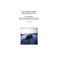
MAIB SAFETY BULLETIN 1/2009<br />
Catastrophic Failure of High Pressure<br />
Hydraulic Anchor Windlasses<br />
<strong>Marine</strong> <strong>Accident</strong> <strong>Investigation</strong> <strong>Branch</strong><br />
Mountbatten House<br />
Grosvenor House<br />
Southampton<br />
SO15 2JU
MAIB SAFETY BULLETIN 1/2009<br />
This document, containing an urgent safety recommendation, has been produced for marine safety<br />
purposes only, on the basis of information available to date.<br />
The Merchant Shipping (<strong>Accident</strong> Reporting and <strong>Investigation</strong>) Regulations 2005 provide for the<br />
Chief Inspector of <strong>Marine</strong> <strong>Accident</strong>s to make recommendations at any time during the course of an<br />
investigation if, in his opinion, it is necessary or desirable to do so.<br />
This Safety Bulletin is issued to raise awareness of the potentially life threatening danger caused by a<br />
series of accidents involving hydraulic windlass motors, probably as a result of excessive tension being<br />
placed on the anchor chain. It recommends windlass manufacturer TTS Kocks GmbH immediately<br />
determines the technical causes for several recent catastrophic failures of its equipment and provide<br />
engineering and design solutions to prevent similar failures in the future.<br />
The Safety Bulletin is published with the support of the Australian Transport Safety Bureau (ATSB),<br />
the German Federal Bureau of Maritime Casualty <strong>Investigation</strong> (BSU), and the Bahamas Maritime<br />
Authority (BMA).<br />
Stephen Meyer<br />
Chief Inspector of <strong>Marine</strong> <strong>Accident</strong>s<br />
This bulletin is also available on our website: www.maib.gov.uk<br />
Press Enquiries: 020 7944 3231/3387; Out of hours: 020 7944 4292<br />
Public Enquiries: 0300 330 3000
BACKGROUND<br />
Since 2007, the MAIB has been made aware of the catastrophic failure of a number of high<br />
pressure hydraulic anchor windlasses. Of those that have occurred, the following are particularly<br />
noteworthy:<br />
• On 25 June 2007, the tanker Young Lady started to drag her anchor in Tees Bay, UK. The<br />
vessel was in ballast, the wind speed was in excess of 40 knots and there was a heavy<br />
northerly swell. The master decided to weigh anchor and depart, but during the operation<br />
the Nippon Pusnes windlass hydraulic motor suffered a catastrophic failure and the cable<br />
ran out to the bitter end. The vessel continued to drag her anchor until the anchor flukes<br />
snagged on a submerged gas pipeline (MAIB investigation report 3/2008).<br />
• On 13 December 2008, the hydraulic motor casing of the TTS Kocks high pressure windlass<br />
on board the Hong Kong, China registered container ship APL Sydney, fractured as the<br />
vessel was heaving in her anchor in Port Philip Bay, Melbourne, shortly after the anchor had<br />
dragged in gale force winds and had ruptured a submerged gas pipeline. There were no<br />
injuries. This accident is being investigated by the Australian Transport Safety Bureau which<br />
also identified another failure of anchor windlass hydraulic motor while investigating the<br />
grounding of the Singapore registered woodchip carrier Crimson Mars in May 2006.<br />
• On 23 March 2009, the hydraulic motor of the TTS Kocks high pressure windlass on board<br />
the Bahamas registered crude oil tanker Stellar Voyager exploded as the vessel attempted<br />
to weigh anchor in Tees Bay, UK. With the wind gusting up to 30 knots and a 2m swell,<br />
the anchor chain was under considerable tension. The windlass motor was in the ‘heave’<br />
position but the anchor chain had started to render or pay out. When the windlass motor<br />
casing shattered, the windlass operator was seriously injured by debris, some of which was<br />
thrown as far as 40m. This accident is being investigated by the MAIB and the Bahamas<br />
Maritime Authority.<br />
Preliminary findings of metallurgical examination of the failed components recovered from<br />
Stellar Voyager have identified:<br />
• There is no evidence of damage caused by fatigue, metallurgical defects or impact.<br />
• The toughened steel cylinder and pistons of the axial piston displacement motor had<br />
been subjected to extremely high internal pressures.<br />
• Signs that the outer cast iron casing had fractured under extreme internal pressure<br />
and on impact with broken components of the hydraulic motor.<br />
• On 19 May 2009, the hydraulic motor of the TTS Kocks high pressure windlass on board a<br />
German registered LPG vessel exploded as the vessel was heaving in her anchor off the<br />
coast of Florida, USA. The vessel was in ballast and the wind speed was up to 38 knots.<br />
The windlass operator was seriously injured by the flying debris. This accident is being<br />
investigated by the vessel’s owners and her classification society.
SAFETY ISSUES<br />
The frequency and consequences of the catastrophic failures of high pressure windlass motors<br />
highlighted is a serious cause for concern. These and other similar accidents appear to have<br />
occurred when heaving in the anchor in adverse sea and weather conditions when the anchor chain<br />
has been tensioned beyond the intended safe loading of its windlass. This can be avoided by:<br />
• Closely monitoring the predicted weather and sea conditions and ensuring that the anchor is<br />
recovered in good time, before the conditions make this difficult to achieve; and<br />
• Using main engines to manoeuvre a vessel to relieve tension in the anchor chain before<br />
‘heaving in’. This also helps to prevent an anchor from ‘breaking out’ and dragging while<br />
weighing.<br />
However, the risk of an anchor chain suddenly tensioning can never be fully eliminated. Therefore,<br />
until technical solutions are introduced by all windlass manufacturers that prevent the over-loading<br />
of high pressure windlasses resulting in their catastrophic failure, it is imperative that an anchor<br />
chain is closely monitored when weighing, and that ‘heaving in’ is stopped as soon as any significant<br />
tensioning is observed or difficulty is experienced.<br />
RECOMMENDATION<br />
While it is recognised that in the longer term the risk of catastrophic failures to all windlass motors<br />
will need to be addressed by more stringent industry performance standards, in view of the recent<br />
accidents involving its equipment, TTS Kocks GmbH is recommended to expedite its action to:<br />
2009/140S Identify the technical reasons for the catastrophic failures of its windlass<br />
motors and determine engineering and design solutions to prevent similar<br />
accidents on board vessels fitted with its equipment.<br />
REQUEST FOR INFORMATION<br />
To gain an accurate assessment of the incidence of the catastrophic failure of anchor windlasses, all<br />
ship owners, ship managers, windlass manufacturers, classification societies and marine accident<br />
investigation organisations are requested to forward details of any incidents which have resulted in<br />
the fracture of the windlass motor casing. All information, which ideally should include the date of<br />
the occurrence, the vessel’s name, details of any injuries, and the manufacturer of the windlass, will<br />
be treated in confidence and only used for the purpose of accident investigation. Reports should be<br />
forwarded to maib@dft.gsi.gov.uk with the title ‘windlass motor fractures’.<br />
Issued August 2009