Katalog - Ruhstrat GmbH
Katalog - Ruhstrat GmbH
Katalog - Ruhstrat GmbH

Create successful ePaper yourself
Turn your PDF publications into a flip-book with our unique Google optimized e-Paper software.
Technische Erläuterungen<br />
Technical Explantions<br />
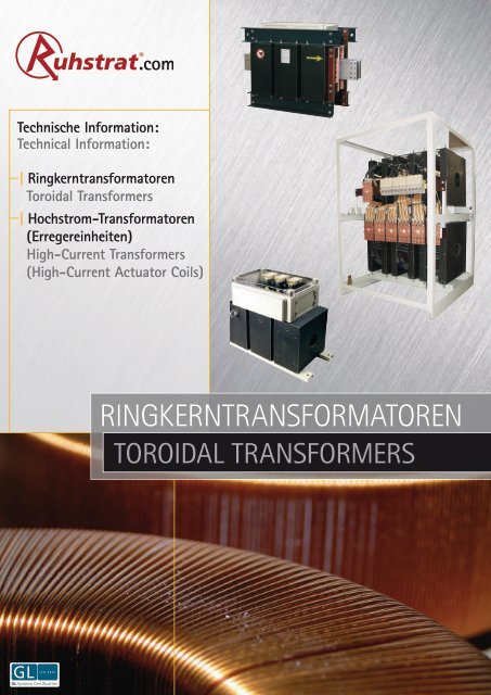
Technische Information:<br />
Technical Information:<br />
| Ringkerntransformatoren<br />
Toroidal Transformers<br />
| Hochstrom-Transformatoren<br />
(Erregereinheiten)<br />
High-Current Transformers<br />
(High-Current Actuator Coils)<br />
Ringkerntransformatoren<br />
Toroidal Transformers<br />
1<br />
<strong>Ruhstrat</strong> <strong>GmbH</strong> · Heinestraße 12 · 37120 Bovenden · Germany phone +49(0)5593803-0 · fax +49(0)5593803-50 e-mail: info@ruhstrat.com · www.ruhstrat.com
Inhalt<br />
Table of Contents<br />
Technische Erläuterungen<br />
Technical Explanations<br />
3<br />
Ringkerntransformatoren<br />
nach<br />
DIN EN 61558<br />
( VDE 0532 / 0570 )<br />
according to<br />
DIN EN 61558<br />
( VDE 0532 / 0570 )<br />
8<br />
Hochstrom-Transformatoren<br />
( Erregereinheiten )<br />
High-Current Transformers<br />
( High Current Actuator Coils )<br />
nach<br />
DIN EN 61558<br />
( VDE 0532 / 0570 )<br />
according to<br />
DIN EN 61558<br />
( VDE 0532 / 0570 )<br />
10<br />
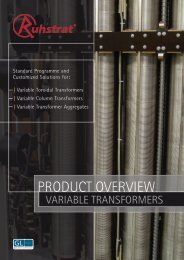
Produktübersicht:<br />
| Stelltransformatoren von 20 VA bis 2 MVA<br />
• Ringstelltransformatoren<br />
• Säulenstelltransformatoren<br />
| Spannungskonstanthalter von 60 VA bis 2 MVA<br />
• Magnetische Spannungskonstanthalter<br />
• Transformatorische Spannungskonstanthalter<br />
| Leistungstransformatoren von 50 VA bis 8 MVA<br />
• Niederspannungs-Trocken-Transformatoren<br />
• Gießharztransformatoren<br />
| AC / DC Drosseln<br />
• als Netzdrosseln, Glättungsdrosseln, Kompensationsdrosseln,<br />
Filterkreisdrosseln<br />
| Ringkerntransformatoren bis 400 kVA<br />
| Hochstromtransformatoren bis 30 kA<br />
| Leistungswiderstände bis 5 MW<br />
• Rohrwiderstände<br />
• Prüfwiderstände<br />
• Laborwiderstände<br />
• Lastwiderstände<br />
Product overview:<br />
| Variable transformers from 20 VA up to 2 MVA<br />
• Variable toroidal transformers<br />
• Variable column transformers<br />
| Voltage stabilizers from 60 VA up to 2 MVA<br />
• Magnetic voltage stabilizers<br />
• Transformer-type voltage stabilizers<br />
| Power transformers from 50 VA up to 8 MVA<br />
• Low-voltage dry-type transformers<br />
• Cast resin transformers<br />
| AC / DC reactors<br />
• as power reactors, smoothing reactors, compensation<br />
reactors, filter circuit reactors<br />
| Toroidal transformers up to 400 kVA<br />
| High-current transformers up to 30 kA<br />
| Power resistors up to 5 MW<br />
• Tube resistors<br />
• Test resistors<br />
• Lab resistors<br />
• Load resistors<br />
2<br />
<strong>Ruhstrat</strong> <strong>GmbH</strong> · Heinestraße 12 · 37120 Bovenden · Germany phone +49(0)5593803-0 · fax +49(0)5593803-50 e-mail: info@ruhstrat.com · www.ruhstrat.com
Technische Erläuterungen<br />
Technical Explantions<br />
<strong>Ruhstrat</strong>-Ringkerntransformatoren in ein- und dreiphasiger Ausführung<br />
entsprechen den gültigen DIN VDE- und EN-Vorschriften.<br />
Allgemeines<br />
Dieser <strong>Katalog</strong> enthält eine Übersicht des <strong>Ruhstrat</strong>-Standardprogramms<br />
für Ringkerntransformatoren.<br />
Vom Standardprogramm abweichende Applikationen sind unsere<br />
Stärke! Jedes Produkt kann für Ihre spezielle Anwendung maßgeschneidert<br />
werden.<br />
Qualitätskontrolle<br />
Jeder Ringkerntransformator wird während der Fertigung einer Zwischenprüfung<br />
und nach der Fertigung einer eingehenden elektrischen<br />
100 % igen Endprüfung nach den jeweils gültigen Verfahrensanweisungen<br />
unterzogen. Die Dokumentation der Messergebnisse erfolgt<br />
gemäß Qualitätsstandard DIN ISO 9001 in entsprechenden Prüfprotokollen.<br />
Durch den Einsatz hochwertiger Materialien und der Fachkompetenz<br />
der Mitarbeiter ist ein hoher Qualitätsstandard gewährleistet.<br />
Technische Erläuterungen<br />
Die Ringkerntransformatoren werden entsprechend den gültigen<br />
einschlägigen VDE / EN-Vorschriften gefertigt. Als Kernmaterial wird<br />
verlustarmes kaltgewalztes Elektroblech mit magnetischer Vorzugsrichtung<br />
verwendet. Die Wicklungen werden aus Kupferrunddraht<br />
hergestellt. Die weiteren Isolationsmaterialien werden nach der Temperaturbeständigkeitsklasse<br />
ausgewählt.<br />
Leistung<br />
Die Leistung errechnet sich als Produkt aus Sekundärspannung [ V ]<br />
und Sekundärstrom [ A ] zu [ kVA ]. Alle Leistungsangaben beziehen<br />
sich auf die sekundärseitig abnehmbare Leistung bei:<br />
• Dauerbetrieb (S1)<br />
• Erregung mit Nennspannung<br />
• Nennfrequenz 50 / 60 Hz<br />
• einer Umgebungstemperatur von max. 40 °C und<br />
• einer Aufstellhöhe bis 1.000 m über NN<br />
• cos. phi = 1<br />
Überlastung<br />
Grundsätzlich können die Ringkerntransformatoren unter Einhaltung<br />
der mittleren Grenztemperatur kurzzeitig mit höheren Strömen belastet<br />
werden.Grenzwerte für den Kurzzeitbetrieb ( S2 ) ergeben sich<br />
aus Abb. 1.<br />
<strong>Ruhstrat</strong> Toroidal Transformers in the design single-phase and threephase,<br />
fulfill the current DIN VDE / EN regulations.<br />
General<br />
This catalogue provides a general idea of <strong>Ruhstrat</strong>’s standardprogramme<br />
for transformers with fixed transformation ratio, constructed<br />
as toroidal core or limb core transformers.<br />
Applications deviating from the standard programme are our strong<br />
point! Every product can be tailor-made according to your special<br />
application.<br />
Quality Control<br />
During its production every toroidal transformer has to undergo<br />
an intermediate test and after its production it has to undergo a<br />
thorough final electrical test; this is always done according to the<br />
respectively valid process instructions. According to the quality standard<br />
DIN ISO 9001 the documentation of the measuring results is<br />
effected in appropriate test certificates.<br />
A high quality standard is guaranteed by the use of high-quality materials<br />
and by the special competence of the employees.<br />
Technical Explanations<br />
The toroidal transformers are manufactured according to the valid<br />
relevant VDE / EN regulations. Sheets for the electrical industry,<br />
cold-rolled and low-loss, with privileged magnetic direction are used<br />
for the cores. The windings are made of round copper wire. Further<br />
materials are chosen according to their temperature stability class.<br />
Power<br />
Power is calculated as the product of secondary voltage [ V ] and secondary<br />
current [ A ], the result is [ kVA ]. All power specifications refer<br />
to the collected power at the secondary side with:<br />
• continuous operation (S1)<br />
• excitation with rated voltage<br />
• rated frequency 50/60 Hz<br />
• an ambient temperature of max. 40 °C and<br />
• an altitude of installation up to 1.000 m above MSL<br />
• (load) power factor (LPF) = 1<br />
Overload<br />
In principle, the toroidal transformers can be loaded with higher currents<br />
for a short period of time, if the average temperature limit is<br />
kept. The limit values for short-time operation (S2) arise from fig 1.<br />
Abb. 1<br />
Grenzwerte für Überlastung<br />
im Kurzzeitbetrieb<br />
A: Überlastung im Kaltzustand<br />
B: Überlastung im Warmzustand<br />
fig. 1<br />
limit values for overload during<br />
short-time operation<br />
A: overload in cold state<br />
B: overload in warm state<br />
3<br />
<strong>Ruhstrat</strong> <strong>GmbH</strong> · Heinestraße 12 · 37120 Bovenden · Germany phone +49(0)5593803-0 · fax +49(0)5593803-50 e-mail: info@ruhstrat.com · www.ruhstrat.com
Technische Erläuterungen<br />
Technical Explantions<br />
Erwärmung<br />
Die zulässigen Grenztemperaturen, die in den entsprechenden VDE /<br />
EN-Vorschriften genannt sind, werden bei bestimmungsgemäßem<br />
Betrieb der Ringkerntransformatoren und einer maximalen Umgebungstemperatur<br />
von 40 °C nicht überschritten.<br />
Bei einer Umgebungstemperatur über 40 °C darf der Ringkerntransformator<br />
wegen der möglichen Überschreitung der höchstzulässigen<br />
Grenzübertemperatur der Wicklung nicht mit dem vollen Nennstrom<br />
belastet werden.<br />
Für eine ausreichende Belüftung bzw. ungehinderten Zutritt der Kühlluft<br />
am Aufstellungsort des Ringkerntransformators ist zu sorgen!<br />
Umgebungstemperatur[ °C ] 40 45 50 55 60<br />
Isolierstoffklasse B 1,0 0,96 0,92 0,88 0,82<br />
Isolierstoffklasse F 1,0 0,97 0,94 0,90 0,86<br />
Isolierstoffklasse H 1,0 0,98 0,95 0,92 0,90<br />
Tab. 1<br />
Faktoren zur Korrektur der Nennleistung bei Umgebungstemperatur<br />
über 40 ° C<br />
Aufstellungshöhe<br />
Die für die Ringkerntransformatoren angegebenen Nennleistungen<br />
gelten für eine Aufstellungshöhe bis 1.000 m über dem Meeresspiegel.<br />
Wie bei einer überhöhten Umgebungstemperatur muss auch bei<br />
einer Aufstellungshöhe von über 1.000 m über dem Meeresspiegel<br />
eine Leistungsminderung vorgenommen werden. Dies ist notwendig,<br />
da der geringe Luftdruck zu einer verminderten Kühlung führt.<br />
Aufstellungshöhe[m] 1.000 1.500 2.000 2.500 3.000 3.500<br />
bis<br />
Isolierstoffklasse B 1,0 0,98 0,97 0,93 0,92 0,89<br />
Isolierstoffklasse F 1,0 0,98 0,97 0,94 0,93 0,90<br />
Isolierstoffklasse H 1,0 0,98 0,97 0,94 0,93 0,91<br />
Tab. 2<br />
Faktoren zur Korrektur der Nennleistung bei Betrieb in<br />
großen Höhen<br />
Lastart<br />
Die aufgeführten Standardtransformatoren beziehen sich auf reine<br />
Wirklast. Andere abweichende Belastungsarten und die Anschnittsteuerung<br />
der Transformatoren sind bei der Auslegung zu berücksichtigen.<br />
Isolation<br />
Eine wichtige Grundvoraussetzung für eine lange Lebensdauer und<br />
hohe Betriebssicherheit eines Transformators ist, dass kein Teil eine<br />
unzulässig hohe Temperatur annimmt. Am empfindlichsten gegen<br />
Wärme ist die Isolation der Wicklungen, die nur eine begrenzte Temperatur<br />
bei einer normalen Lebensdauer verträgt.<br />
Der Isolationsaufbau gestattet die Verwendung der Ringkerntransformatoren<br />
in trockenen Räumen. Die Ringkerntransformatoren werden<br />
teilvergossen (Schutzart IP00) bzw. vollvergossen (Schutzart IP54)<br />
ausgeführt. In der Schutzart IP54 sind die Ringkerntransformatoren<br />
gegen äußere Einflüsse geschützt.<br />
Warming<br />
The admissible temperature limits stipulated in the respective VDE /<br />
EN regulations are not exceeded, if the toroidal transformers are duly<br />
operated and if the ambient temperature does not rise above a maximum<br />
of 40 °C.<br />
With an ambient temperature above 40 °C the toroidal transformer<br />
must not be charged with the full rated current, due to the possible<br />
exceeding of the highest admissible overtemperature limit of<br />
the winding.<br />
It has to be ensured that there is a sufficient ventilation resp. unhindered<br />
entry of cool air at the toroidal transformer’s site of installation!<br />
ambient temperature[ °C ] 40 45 50 55 60<br />
insulant class B 1.0 0.96 0.92 0.88 0.82<br />
insulant class F 1.0 0.97 0.94 0.90 0.86<br />
insulant class H 1.0 0.98 0.95 0.92 0.90<br />
table 1<br />
factors for the correction of the rated power with ambient<br />
temperatures above 40 ° C<br />
Altitude of installation<br />
The rated powers stipulated for the toroidal transformers are valid<br />
for an altitude of installation of 1.000 m above main sea level. With<br />
an altitude of installation of more than 1.000 m above main sea level<br />
it is the same as with an excessive overtemperature: a power reduction<br />
has to be carried out. This is necessary, as the smaller atmospheric<br />
pressure leads to reduced cooling.<br />
altitude of installation<br />
[m] up to<br />
1.000 1.500 2.000 2.500 3.000 3.500<br />
insulant class B 1.0 0.98 0.97 0.93 0.92 0.89<br />
insulant class F 1.0 0.98 0.97 0.94 0.93 0.90<br />
insulant class H 1.0 0.98 0.97 0.94 0.93 0.91<br />
table 2<br />
factors of the correction of the rated power with operation<br />
at high altitudes<br />
Kind of Load<br />
The standard transformers stipulated refer to pure real load.<br />
Other deviating kinds of load and the phase shift control of the<br />
transformers must be considered when they are constructed.<br />
Insulation<br />
For long life and high operation safety of a transformer it is very<br />
important that no part takes on an inadmissibly high temperature.<br />
The insulation of the windings is most sensitive against warmth,<br />
as it can only bear a limited temperature with a normal duration<br />
of life.<br />
The insulation structure allows the use of toroidal transformers in dry<br />
rooms. Through this the toroidal transformers are protected against<br />
external influences.<br />
4<br />
<strong>Ruhstrat</strong> <strong>GmbH</strong> · Heinestraße 12 · 37120 Bovenden · Germany phone +49(0)5593803-0 · fax +49(0)5593803-50 e-mail: info@ruhstrat.com · www.ruhstrat.com
Technische Erläuterungen<br />
Technical Explantions<br />
Zulässige Wicklungstemperatur<br />
Die Wicklungstemperatur darf die von der Isolierstoffklasse abhängige<br />
Grenztemperatur nicht überschreiten. Die Grenztemperatur ist<br />
die höchstzulässige Dauertemperatur der Wicklung an der heißesten<br />
Stelle. Die Grenztemperatur ergibt sich, indem die Umgebungstemperatur<br />
( 40 °C ), die zulässige Grenzübertemperatur und ein Sicherheitszuschlag<br />
addiert werden.<br />
Admissible winding temperature<br />
The winding temperature may not exceed the limit temperature<br />
which depends on the insulant class. The limit temperature is the<br />
highest admissible permanent temperature of the winding at the hottest<br />
point. The limit temperature emerges when adding the ambient<br />
temperature ( 40 °C ), the admissible limit overtempertature and a<br />
safety addition.<br />
Isolierstoffklasse<br />
Zulässige Grenzübertemperatur<br />
[ K ]<br />
Grenztemperatur des<br />
Isolierstoffsystems [ °C ]<br />
Isolierstoffklasse B 80 130<br />
Isolierstoffklasse F 100 155<br />
Isolierstoffklasse H 125 180<br />
insulant class<br />
admissible limit overtemperature<br />
[ K ]<br />
limit temperature of<br />
the insulant system [ °C ]<br />
insulant class B 80 130<br />
insulant class F 100 155<br />
insulant class H 125 180<br />
Tab. 3<br />
Grenzübertemperatur und Grenztemperatur der<br />
Isolierstoffklasse B, F, H<br />
table 3<br />
limit overtemperature and limit temperature of the insulant<br />
classes B, F, H<br />
Ringkerntransformatoren mit getrennter Wicklung<br />
Bei diesen Transformatoren besteht keine elektrisch leitende Verbindung<br />
zwischen der Primär- und Sekundärwicklung, da diese galvanisch<br />
voneinander getrennt sind.<br />
Anzapfungen<br />
Ringkerntransformatoren können sowohl primär- als auch sekundärseitig<br />
mit Anzapfungen ausgeführt werden. Anzapfungen der Primärseite<br />
dienen der Anpassung des Ringkerntransformators an verschiedene<br />
Netzspannungstoleranzen.<br />
Ringkerntransformatoren mit Sparwicklung<br />
Spartransformatoren haben eine aus zwei Teilen bestehende Wicklung.<br />
Beide Wicklungsteile sind hintereinander geschaltet und werden<br />
vom gleichen magnetischen Fluss durchsetzt. Der Spartransformator<br />
hat die gleiche Wirkungsweise wie der Transformator mit getrennter<br />
Wicklung, der auch als Volltransformator bezeichnet wird, und erlaubt<br />
ebenfalls das Herauf- und Heruntertransformieren von Spannungen,<br />
jedoch keine galvanische Trennung. Beim Spartransformator<br />
wird jedoch, im Gegensatz zum Volltransformator, nur ein Teil der<br />
Ausgangsleistung durch magnetische Induktion von der Eingangszur<br />
Ausgangswicklung übertragen. Die Übertragung des anderen Teils<br />
der Ausgangsleistung erfolgt durch unmittelbare Stromleitung. Deshalb<br />
wird beim Spartransformator zwischen Durchgangsleistung und<br />
Bauleistung unterschieden. Die Bauleistung und damit die Baugröße<br />
des Transformators verringert sich, gegenüber Transformatoren mit<br />
getrennter Wicklung, beachtlich durch die Einsparung an Kerneisen<br />
und Wicklungskupfer. Sie ist um so größer, je kleiner die Differenz zwischen<br />
Eingangs- und Ausgangsspannung ist.<br />
Toroidal Transformers with separate winding<br />
With these transformers there is no electrically conducting connection<br />
between the primary and secondary winding, as these are galvanically<br />
separated from each other.<br />
Taps<br />
Transformers can be constructed with taps on the primary as well as<br />
on the secondary side. Taps on the primary side serve for the adaptation<br />
of the toroidal transformer to different mains voltage tolerances.<br />
Toroidal Transformers with autowinding<br />
Autotransformers have a winding which consists of two parts. Both<br />
winding parts are connected in series and are interspersed by the<br />
same magnetic flux. The autotransformer has the same mode of operation<br />
as the transformer with separate winding, which is also called<br />
transformer and also allows to step up and down voltages, but no<br />
physical separation. In contrast to the complete transformer, there is<br />
only a part of the output power transferred from the input winding<br />
to the output winding with the autotransformer, by means of magnetic<br />
induction. The transfer of the other part of the output power is<br />
effected by means of direct current conduction. Therefore, referring<br />
to the autotransformer one distinguishes between transit-circuit power<br />
and structural power.<br />
The structural power and consequently the size of the transformer diminishes<br />
considerably compared to transformers with separate winding,<br />
due to the saving of core iron and winding copper. The smaller<br />
the difference between input voltage and output voltage, the larger<br />
is the structural power.<br />
Primär-Spannung | primary voltage 2 Primär-Spannungen | 2 primary voltages Primär-Spannungen | primary voltages<br />
Sekundär-Spannung | secondary voltage Sekundär-Spannung | secondary voltage Sekundär-Spannung | secondary voltage<br />
Abb. 2 Schaltbild Transformator mit getrennter Wicklung und primärseitiger Anzapfung<br />
fig. 2 wiring diagram transformer with seperate winding and tap on the primary side<br />
Abb. 2 Schaltbild Transformator mit Sparwicklung<br />
fig. 2 wiring diagram transformer with autowinding<br />
5<br />
<strong>Ruhstrat</strong> <strong>GmbH</strong> · Heinestraße 12 · 37120 Bovenden · Germany phone +49(0)5593803-0 · fax +49(0)5593803-50 e-mail: info@ruhstrat.com · www.ruhstrat.com
Technische Erläuterungen<br />
Technical Explantions<br />
Schutzarten<br />
Je nach Aufstellungsort und Verwendungszweck müssen die unter<br />
Spannung stehenden Teile von Transformatoren gegen zufällige<br />
Berührung und gegen das Eindringen von Wasser und Fremdkörpern<br />
geschützt sein. Aus diesem Grund werden verschiedene Schutzarten<br />
unterschieden. Die Schutzarten werden durch ein Kurzzeichen angegeben,<br />
welche sich aus zwei Kennziffern für den Schutzgrad zusammensetzen.<br />
Die erste Ziffer macht eine Aussage über den Schutzgrad<br />
gegen Berührung und Eindringen von Fremdkörpern. Die zweite Ziffer<br />
kennzeichnet den Schutz gegen das Eindringen von Wasser.<br />
Schaltgruppen von Drehstrom-Transformatoren<br />
Als Schaltgruppe des Drehstrom-Transformators wird die Kombination<br />
der verschiedenen Schaltungsmöglichkeiten von Ober- und<br />
Unterspannungswicklung bezeichnet. Die Schaltgruppe besteht aus<br />
mindestens einem großen und einem kleinen Buchstaben sowie einer<br />
Kennzahl. Haben Drehstrom-Transformatoren einen herausgeführten<br />
Sternpunkt, wird die Schaltgruppe durch ein „N” oder „n” ergänzt.<br />
Der große Buchstabe wird der Eingangswicklung, der Kleine der Ausgangswicklung<br />
zugeordnet. Je nach Anschluss der Verbraucher an<br />
Wicklungsanfang oder -ende der Unterspannungsseite ergeben sich<br />
zwischen Ober- und Unterspannungen Phasenverschiebungen von<br />
0° bzw. 180° und 150° bzw. 330°. Diese Phasenverschiebung gibt<br />
man durch die Kennzahlen 0, 5, 6 und 11 an, wobei der Phasenverschiebungswinkel<br />
das Produkt aus der Kennzahl und dem Winkel von<br />
30° ist.<br />
Degrees of Protection<br />
Depending on the site of installation and the intended purpose the<br />
parts of the transformer which are under voltage have to be protected<br />
against accidental touching and against penetration of water<br />
and foreign bodies. For this reason, different kinds of protection are<br />
distinguished. The kinds of protection are indicated by a short sign<br />
which consists of two reference numbers for the degree of protection.<br />
The first reference number gives an information about the protection<br />
degree against touching and penetration of foreign bodies. The<br />
second reference number marks the protection against the penetration<br />
of water.<br />
Vector Groups of Three-Phase Transformers<br />
The combination of the different connection systems for highvoltage<br />
winding and low-voltage winding is called vector group of the<br />
three-phase transformer. The vector group consists of at least one<br />
capital letter and one small letter as well as of a reference number. If<br />
three-phase transformers have a neutral point (star point) which is<br />
lead outside, the vector group is completed by an “N” or “n”. The capital<br />
letter stands for the input winding, the small one for the output<br />
winding. Depending on the connection of the consumer to the winding’s<br />
beginning or end of the low-voltage side phase displacements<br />
from 0° resp. 180° and 150° resp. 330° arise between high voltages<br />
and low voltages. This phase displacement is stated by the reference<br />
numbers 0, 5, 6 and 11, whereas the phase displacement angle is the<br />
product of the reference number and the angle of 30°.<br />
Bezeichnung<br />
Kennzahl<br />
re.number<br />
designation<br />
Schaltgruppe<br />
vector group<br />
Zeigerbild | vector diagram<br />
Schaltungsbild | wiring picture<br />
sekundär | secondary<br />
Sternpunkt | neutral point (star point)<br />
Dd0<br />
nicht vorhanden | not available<br />
0<br />
Yy0<br />
10 % belastbar | 10 % loadable<br />
Yz0<br />
voll belastbar | fully loadable<br />
Dy5<br />
voll belastbar | fully loadable<br />
5<br />
Yd5<br />
nicht vorhanden | not available<br />
Yz5<br />
voll belastbar | fully loadable<br />
Dd6<br />
nicht vorhanden | not available<br />
6<br />
Yy6<br />
10 % belastbar | 10 % loadable<br />
Dz6<br />
voll belastbar | fully loadable<br />
Dy11<br />
voll belastbar | fully loadable<br />
11<br />
Yd11<br />
nicht vorhanden | not available<br />
Yz11<br />
voll belastbar | fully loadable<br />
0 Ya0 10 % belastbar | 10 % loadable<br />
Tab. 4 Schaltgruppen für Drehstrom-Transformatoren table 4 vector groups of three-phase transformers<br />
6<br />
<strong>Ruhstrat</strong> <strong>GmbH</strong> · Heinestraße 12 · 37120 Bovenden · Germany phone +49(0)5593803-0 · fax +49(0)5593803-50 e-mail: info@ruhstrat.com · www.ruhstrat.com
Ringkerntransformatoren nach DIN EN 61558 ( VDE 0532 / 0570 )<br />
Toroidal Transformers According to DIN EN 61558 ( VDE 0532 / 0570 )<br />
1. Aufbau<br />
Beim Ringkerntransformator ist der Kern in sich geschlossen. Das<br />
Blech wird in Walzrichtung aufgespult. Dadurch entspricht die Magnetisierungsrichtung<br />
100 % ig der Walzrichtung. Der Ringkerntransformator<br />
hat einen kleinstmöglichen Luftspalt, also den geringstmöglichen<br />
magnetischen Widerstand.<br />
2. Vorteile<br />
Durch den physikalisch günstigen Kernaufbau ergibt sich zwangsläufig<br />
ein geringes magnetisches Störfeld. Der Einsatz von <strong>Ruhstrat</strong><br />
Ringkerntransformatoren empfiehlt sich daher überall dort, wo das<br />
Streufeld klein gehalten werden muss und Gewicht und Volumen entscheidend<br />
sind. Der Dreiphasen-Ringkerntransformator besteht aus<br />
3 Einzeltransformatoren mit einem jeweils separaten Eisenkern. Bei<br />
Ausfall einer Phase im Eingang des Dreiphasen-Ringkerntransformators<br />
bleibt mindestens eine Phase im Ausgang ohne Spannungsverschiebung<br />
unverändert wirksam. Die vollvergossene Ausführung der<br />
Ringkerntransformatoren ermöglicht höhere Schutzarten und, damit<br />
verbunden, eine höhere Schutzklasse.<br />
3. Wicklung<br />
<strong>Ruhstrat</strong>-Ringkerntransformatoren werden, wenn nicht anders gewünscht,<br />
mit galvanisch getrennten Wicklungen geliefert. Bei einer<br />
Ausführung in Sparwicklung verringert sich die Bauleistung gegenüber<br />
der Nennleistung.<br />
4. Schutzarten<br />
Es sind folgende Standard-Schutzarten möglich:<br />
a) Schutzart IP00 – Durch Eingießen des bewickelten Ringkerns<br />
in Gießharz wird eine einfache mechanische Befestigung<br />
der Ringkerntransformatoren ermöglicht. Die Wicklung<br />
liegt in der Schalenbauform im Außenumfang frei.<br />
b) Schutzart IP54 – Bei der Kompaktbauform wird der Transformator<br />
vollständig eingegossen. Durch den Vollverguss ergibt<br />
sich eine weitgehende Unempfindlichkeit gegenüber mechanischen,<br />
atmosphärischen und chemischen Einflüssen.<br />
Die Anschlüsse sind in einem Isolierstoffgehäuse angeordnet.<br />
c) Schutzart IP54 / Anschluss IP00 – Auf Wunsch können bei der<br />
Kompaktbauform die Anschlüsse auch als Anschlussbolzen (nicht abgedeckt)<br />
oder als freie Anschlussenden herausgeführt werden.<br />
5. Spannungen<br />
Die Ausführungen gelten für einen Bereich von 230 V bis 500 V und<br />
primärseitiger Anzapfung von ±5 %.<br />
6. Frequenz<br />
<strong>Ruhstrat</strong>-Ringkerntransformatoren sind für eine Betriebsfrequenz<br />
von 50 / 60 Hz ausgelegt. Abweichende Frequenzen, wie 16 2 / 3 Hz<br />
oder 400 Hz müssen bei der Bestellung angegeben werden.<br />
7. Vorschriften<br />
Die Ringkerntransformatoren werden nach den jeweils gültigen DIN<br />
VDE- und EN-Bestimmungen gefertigt. Die Berücksichtigung weiterer<br />
Vorschriften, wie bestimmter Schiffsklassifikationen, sind auf<br />
Anfrage möglich.<br />
8. Anwendungsbeispiele<br />
Prüffelder, Maschinensteuerungen, Fahrzeugbau, Automatisierungstechniken,<br />
als Ringkern-Trenntransformator zur Versorgung medizinischer<br />
Räume, als Hochstrom-Transformator bis 30 kA usw.<br />
1. Structure<br />
With the toroidal transformer the core is a closed unit. The sheet<br />
is wound in the direction of the rolling. Therefore, the magnetizing<br />
direction completely corresponds to the direction of the rolling. The<br />
toroidal transformer has an air gap which is as small as possible, so it<br />
has the lowest possible magnetic resistance.<br />
2. Advantages<br />
Due to the physically favourable core construction, there is an automatically<br />
low magnetic stray field. The use of <strong>Ruhstrat</strong> toroidal<br />
transformers is recommended wherever the stray field has to be kept<br />
small and weight and volume are decisive. The three-phase toroidal<br />
transformer consists of three single transformers, each one with a<br />
separate iron core. In case of a failure of one phase in the input of the<br />
three-phase toroidal transformer at least one phase in the output remains<br />
as efficient as before without voltage shifting. The completely<br />
casted construction of the toroidal transformers makes higher kinds<br />
of protection possible and, thereby, a higher protection class.<br />
3. Winding<br />
<strong>Ruhstrat</strong> toroidal transformers are delivered with galvanically separate<br />
windings – provided that the customer does not wish anything<br />
else. In case of a construction with autowinding, the structural power<br />
is reduced towards the rated power.<br />
4. Degrees of protection<br />
The following standard degrees of protection are possible:<br />
a) Degree of protection IP00 – By means of pouring the<br />
wound toroidal core into resin an easy mechanical fixing of<br />
the toroidal transformers is made possible. In the shell-building<br />
system the winding lies open in the outer circumference.<br />
b) Degree of protection IP54 – With the compact form of construction<br />
the transformer is completely casted. The complete casting leads to a farreaching<br />
insensitiveness against mechanical, atmospheric and chemical<br />
influences. The connections are arranged in an insulant enclosure.<br />
c) Degree of protection IP54 / Connection IP00 – With the compact<br />
form of construction the connections can also be conducted as connection<br />
bolts (uncovered) or as free cable connection ends, if desired<br />
by the customer.<br />
5. Voltages<br />
The explanations are applicable for a voltage range from 230 V up to<br />
500 V and a tap on the primary side of ±5 %.<br />
6. Frequency<br />
<strong>Ruhstrat</strong> toroidal transformers are designed for an operation frequency<br />
of 50 / 60 Hz. Deviating frequencies like 16 2 / 3 Hz or 400 Hz<br />
must be indicated when placing the order.<br />
7. Regulations<br />
The toroidal transformers are manufactured according to the current<br />
DIN VDE / EN regulations. Further regulations, as for example certain<br />
marine classifications, can be considered upon request.<br />
8. Possibilities of application<br />
Test fields, machine controls, vehicle manufacturing, automatic control<br />
engineering, as toroidal core isolating transformer for the supply<br />
of medical rooms, as high-current transformer up to 30 kA etc.<br />
7<br />
<strong>Ruhstrat</strong> <strong>GmbH</strong> · Heinestraße 12 · 37120 Bovenden · Germany phone +49(0)5593803-0 · fax +49(0)5593803-50 e-mail: info@ruhstrat.com · www.ruhstrat.com
Einphasen-Ringkerntransformatoren in teil- und vollvergossener Ausführung<br />
Single-Phase Toroidal Transformers, partially and fully casted<br />
Einphasen-Ringkerntransformatoren in teil- und vollvergossener Ausführung<br />
Single-Phase Toroidal Transformers, partially and fully casted<br />
8<br />
Abweichende Spannungen, Umgebungstemperaturen und Schutzarten,<br />
Ausführung als Spartransformator, Phasenanschnittsteuerung<br />
usw. auf Anfrage. Bitte bei Bestellungen, die von Ihnen gewählte Primär-<br />
und Sekundär-Spannung, die erforderlichen Anzapfungen sowie<br />
die Frequenz angeben.<br />
Type RTIFTE IP00<br />
Leistung<br />
power<br />
[kVA]<br />
Verluste<br />
losses<br />
Fe<br />
[W]<br />
Cu<br />
[W]<br />
Abmessungen [mm] ca.<br />
dimensions [mm] approx.<br />
B T H B1 T1 D<br />
Cu.-<br />
Gew.<br />
Cu cont.<br />
ca. [kg]<br />
approx<br />
[kg]<br />
Ges.-Gew.<br />
total<br />
weight<br />
ca.[kg]<br />
approx.<br />
[kg]<br />
0.4 3 28 175 90 235 145 65 M6 1.6 7.1<br />
0.5 3 34 178 100 235 145 75 M6 2.3 8<br />
0.63 5 33 175 100 235 145 75 M6 1.9 8.8<br />
0.8 7 39 175 100 235 145 75 M6 2.4 9.6<br />
1 7 63 175 100 235 145 75 M6 2.2 9.4<br />
1.25 7 66 200 110 260 175 85 M6 3.5 12.7<br />
1.6 14 75 270 140 330 220 115 M8 3.7 25.4<br />
2 14 94 270 140 330 220 115 M8 4.9 26.2<br />
2.5 18 90 270 140 330 220 115 M8 5.3 28.9<br />
3 18 96 300 150 360 250 120 M8 7.6 36.7<br />
4 24 113 300 150 360 250 120 M8 8.1 40<br />
5 24 145 315 150 375 260 120 M8 10.7 43<br />
6.3 28 181 360 180 420 310 140 M8 13.5 44.8<br />
8 28 204 440 190 510 390 140 M8 20.9 92.4<br />
10 53 220 440 190 510 390 140 M8 18 97.6<br />
12.5 53 343 440 200 510 390 150 M8 18 101.3<br />
16 77 276 480 230 550 430 180 M8 27.9 142.6<br />
20 77 382 480 240 550 430 190 M8 31.2 149.2<br />
25 112 413 550 240 650 500 190 M12 33 199.4<br />
30 112 482 550 250 650 500 200 M12 40.7 208.4<br />
40 159 507 610 300 710 560 250 M16 47.6 307.6<br />
50 159 557 610 320 710 560 270 M16 67.6 338.3<br />
63 245 632 660 320 760 560 270 M16 57.1 410.8<br />
80 286 720 780 360 880 680 280 M16 76.1 559.7<br />
100 286 943 780 400 880 680 300 M16 91.3 651.6<br />
Tab. 5. IPOO, Type RTIFTE – Verluste, Abmessungen, Gewichte.<br />
Technische Änderungen vorbehalten!<br />
table 5 IPOO, type RTIFTE – losses, dimensions, weights<br />
We reserve the right of technical alterations!<br />
Abb. 3<br />
Spannung: 230 V bis 500 V<br />
Frequenz: 50 / 60 Hz<br />
Schutzart: IP00; teilvergossen<br />
Schutzklasse: 1<br />
T a<br />
:40 °C<br />
fig. 3<br />
voltage: 230 V – 500 V<br />
frequency: 50 / 60 Hz<br />
degree of protection: IP00,<br />
partially casted<br />
protection class: 1<br />
T a<br />
: 40 °C<br />
Deviating voltages, ambient temperatures and kinds of protection,<br />
construction as autotransformer, phase shift control etc. upon request.<br />
When placing the order please indicate your required primary<br />
and secondary voltage, the necessary taps as well as the frequency.<br />
Type RTIFTV IP54<br />
Leistung<br />
power<br />
[kVA]<br />
0.4<br />
Verluste<br />
losses<br />
Fe<br />
[W]<br />
Cu<br />
[W]<br />
Abmessungen [mm] ca.<br />
dimensions [mm] approx.<br />
B T H B1 T1 D<br />
Cu.-<br />
Gew.<br />
Cu cont.<br />
ca. [kg]<br />
approx<br />
[kg]<br />
Ges.-Gew.<br />
total<br />
weight<br />
ca.[kg]<br />
approx.<br />
[kg]<br />
0.5<br />
Auf Anfrage! | upon request!<br />
0.63<br />
<strong>Ruhstrat</strong> <strong>GmbH</strong><br />
0.8<br />
Heinestrasse 12<br />
1<br />
1.25<br />
1.6<br />
7<br />
7<br />
11<br />
47<br />
70<br />
72<br />
180<br />
180<br />
230<br />
100<br />
100<br />
130<br />
280D-37120 130 50 Bovenden-Lenglern<br />
M6 2.2<br />
280Tel 130 +49 (0) 50 55 M6 93 803-0 3.5<br />
340Fax 180 +49 80 (0) 55 M893 803-50 3.7<br />
9.4<br />
12.7<br />
25.4<br />
2 11 81 230 130 340eMail: 180 info@<strong>Ruhstrat</strong>.com<br />
80 M8 4.9 26.2<br />
Internet: www.<strong>Ruhstrat</strong>.com<br />
2.5 18 86 280 160 400 240 110 M8 5.3 28.9<br />
Abteilung: Transformatoren<br />
3 18 102 280 160 400 240 110 M8 7.6 36.7<br />
Tel +49 (0) 55 93 803-37<br />
4 24 113 350 180 480Fax 270 +49 130 (0) 55 M893 803-62 8.1 40<br />
5 24 131 350 180 480eMail:<br />
270 130 M8 10.7 43<br />
6.3 28 126 420 190 550ronny.gorzel@<strong>Ruhstrat</strong>.com3-62<br />
380 140 M8 13.5 44.8<br />
8 28 185 420 190 550Export 380 Division 140 M8 20.9 92.4<br />
phone +49 (0) 55 93 803-17<br />
10 53 220 420 190 550 380 140 M8 18 97.6<br />
fax +49 (0) 55 93 803-80<br />
12.5 53 233 460 220 600 410 170 M8 18 101.3<br />
eMail: export@<strong>Ruhstrat</strong>.com<br />
16 77 245 460 250 600 410 200 M8 27.9 142.6<br />
20 77 312 490 290 630 430 230 M8 31.2 149.2<br />
25 112 335 490 290 630 430 230 M12 33 199.4<br />
30 112 352 520 300 680 430 240 M12 40.7 208.4<br />
40 159 357 520 300 680 430 240 M16 47.6 307.6<br />
50<br />
63<br />
80<br />
100<br />
Auf Anfrage! | upon request!<br />
Tab. 6. IP54, Type RTIFTV – Verluste, Abmessungen, Gewichte.<br />
Technische Änderungen vorbehalten!<br />
table 6 IP54, type RTIFTV – losses, dimensions, weights<br />
We reserve the right of technical alterations!<br />
Abb. 4<br />
Spannung: 230 V bis 500 V<br />
Frequenz: 50 / 60 Hz<br />
Schutzart:IP54; vollvergossen<br />
Schutzklasse: 2<br />
T a<br />
:40 °C<br />
fig. 4<br />
voltage: 230 V – 500 V<br />
frequency: 50 / 60 Hz<br />
degree of protection: IP54,<br />
fully casted<br />
protection class: 2<br />
T a<br />
: 40 °C<br />
<strong>Ruhstrat</strong> <strong>GmbH</strong> · Heinestraße 12 · 37120 Bovenden · Germany phone +49(0)5593803-0 · fax +49(0)5593803-50 e-mail: info@ruhstrat.com · www.ruhstrat.com
Dreiphasen-Ringkerntransformatoren in teil- und vollvergossener Ausführung<br />
Three-Phase Toroidal Transformers, partially and fully casted<br />
Dreiphasen-Ringkerntransformatoren in teil- und vollvergossener Ausführung<br />
Single-Phase Toroidal Transformers, partially and fully casted<br />
Abweichende Spannungen, Umgebungstemperaturen und Schutzarten,<br />
Ausführung als Spartransformator, Phasenanschnittsteuerung<br />
usw. auf Anfrage. Bitte bei Bestellungen, die von Ihnen gewählte Primär-<br />
und Sekundär-Spannung, die erforderlichen Anzapfungen sowie<br />
die Frequenz angeben.<br />
Type DRTIFTE IP00<br />
Abb. 5<br />
Spannung: 230 V bis 500 V<br />
Frequenz: 50 / 60 Hz<br />
Schutzart:IP00; teilvergossen<br />
Schutzklasse: 1<br />
T a<br />
:40 °C<br />
fig. 5<br />
voltage: 230 V – 500 V<br />
frequency: 50 / 60 Hz<br />
degree of protection: IP00,<br />
partially casted<br />
protection class: 1<br />
T a<br />
:40 °C<br />
Deviating voltages, ambient temperatures and kinds of protection,<br />
construction as autotransformer, phase shift control etc. upon request.<br />
When ordering please indicate your required primary and secondary<br />
voltage, the necessary taps as well as the frequency.<br />
Type DRTIFTV IP54<br />
Abb. 6<br />
Spannung: 230 V bis 500 V<br />
Frequenz: 50 / 60 Hz<br />
Schutzart:IP54; vollvergossen<br />
Schutzklasse: 2<br />
T a<br />
:40 °C<br />
fig. 6<br />
voltage: 230 V – 500 V<br />
frequency: 50 / 60 Hz<br />
degree of protection: IP54,<br />
fully casted<br />
protection class: 2<br />
T a<br />
:40 °C<br />
Leistung<br />
power<br />
[kVA]<br />
Fe<br />
[W]<br />
Verluste<br />
losses<br />
Cu<br />
[W]<br />
Abmessungen [mm] ca.<br />
dimensions [mm] approx.<br />
B T H B1 T1 D<br />
Cu.-<br />
Gew.<br />
Cu cont.<br />
ca.[kg]<br />
approx.<br />
[kg]<br />
Ges.-Gew.<br />
total<br />
weight<br />
ca. [kg]<br />
approx<br />
[kg]<br />
1.2 9 93 175 330 235 145 310 7 4.5 23.9<br />
1.5 9 117 175 360 235 145 340 7 5.4 26.4<br />
1.9 15 93 175 360 235 145 340 7 6.6 29.7<br />
2.4 15 132 175 360 235 145 340 7 7.2 31.2<br />
3 21 168 175 360 235 145 340 7 7.5 33.6<br />
3.78 21 204 200 420 280 175 390 9 10.2 41.3<br />
4.8 42 207 270 510 350 220 480 9 12.6 80.8<br />
6 42 234 270 510 350 220 480 9 17.4 84.6<br />
7.5 54 243 270 510 350 220 480 9 18 91.1<br />
9 54 279 300 450 390 250 510 9 22.8 109.1<br />
12 72 372 300 450 390 250 510 9 22.2 115.8<br />
15 72 435 315 450 405 260 510 9 32.7 120.9<br />
19 84 537 360 630 450 310 600 9 41.4 179.3<br />
24 84 561 440 660 540 390 630 9 66 273.8<br />
30 159 699 440 660 540 390 630 9 52.2 282.2<br />
37.5 159 852 440 690 540 390 660 9 66.9 302.1<br />
48 231 765 480 810 580 430 770 12 89.1 439.6<br />
60 231 1191 480 840 580 430 800 12 89.1 453.3<br />
75 336 1578 550 840 680 500 800 12 75.6 587.7<br />
90 336 1518 550 860 680 500 820 12 133.7 633.5<br />
120 477 1641 610 1020 760 560 980 12 123.6 922.9<br />
150 477 1731 610 1080 760 560 1040 12 186.9 991.9<br />
190 735 1905 660 1080 820 560 1040 12 172.2 1226.6<br />
240 858 2583 780 1210 980 680 1170 12 189.9 1789.6<br />
300 858 2976 780 1360 1000 680 1310 12 264.9 1914.2<br />
Tab. 7. IPOO, Type DRTIFTE – Verluste, Abmessungen, Gewichte.<br />
Technische Änderungen vorbehalten!<br />
table 7 IPOO, type DRTIFTE – losses, dimensions, weights<br />
We reserve the right of technical alterations!<br />
Leistung<br />
power<br />
[kVA]<br />
1.2<br />
1.5<br />
1.9<br />
2.4<br />
Fe<br />
[W]<br />
Verluste<br />
losses<br />
Cu<br />
[W]<br />
Abmessungen [mm] ca.<br />
dimensions [mm] approx.<br />
B T H B1 T1 D<br />
Auf Anfrage! | upon request!<br />
Cu.-<br />
Gew.<br />
Cu cont.<br />
ca. [kg]<br />
approx.<br />
[kg]<br />
Ges.-Gew.<br />
total<br />
weight<br />
ca. [kg]<br />
approx.<br />
[kg]<br />
3 21 147 180 360 300 130 340 7 9 36.9<br />
3.78 21 204 180 360 300 130 340 7 10.2 37.8<br />
4.8 33 231 230 470 350 180 440 9 11.4 65.2<br />
6 33 234 230 470 350 180 440 9 18.3 68.3<br />
7.5 54 219 280 560 400 240 530 9 15.9 111<br />
9 54 348 280 560 400 240 530 9 18 112.5<br />
12 72 372 350 630 500 270 600 9 22.2 179.1<br />
15 72 426 350 630 500 270 600 9 32.1 179.8<br />
19 84 537 420 660 580 380 630 9 41.4 258.1<br />
24 159 447 420 660 580 380 630 9 52.2 277.9<br />
30 159 699 420 660 580 380 630 9 52.2 277.9<br />
37.5 159 852 460 750 630 410 720 9 66.9 373.1<br />
48 231 765 460 750 630 410 720 9 89.1 408.1<br />
60 336 1011 490 980 710 430 940 14 75.6 609.2<br />
75 336 1053 490 980 710 430 940 14 113.7 635.4<br />
90 477 927 520 1020 760 430 980 14 123.6 783.7<br />
120 477 1326 520 1020 760 430 980 14 155.4 788.5<br />
150<br />
190<br />
240<br />
300<br />
Auf Anfrage! | upon request!<br />
Tab. 8. IP54, Type DRTIFTV – Verluste, Abmessungen, Gewichte.<br />
Technische Änderungen vorbehalten!<br />
table 8 IP54 type DRTIFTV – losses, dimensions, weights<br />
We reserve the right of technical alterations!<br />
9<br />
<strong>Ruhstrat</strong> <strong>GmbH</strong> · Heinestraße 12 · 37120 Bovenden · Germany phone +49(0)5593803-0 · fax +49(0)5593803-50 e-mail: info@ruhstrat.com · www.ruhstrat.com
Hochstrom-Transformatoren (Erregereinheiten) nach DIN EN 61558 ( VDE 0532 )<br />
High-Current Transformers (High-Current Actuator Coils) According to DIN EN 61558 ( VDE 0532 )<br />
Hochstrom-Transformatoren (Erregereinheiten) nach DIN EN 61558 (VDE 0532)<br />
als Ringkerntransformatoren in vergossener Ausführung<br />
High-Current Transformers (High-Current Actuator Coils) According to DIN EN 61558 (VDE 0532)<br />
as Toroidal Transformers, Cast Construction<br />
Aufbau:<br />
Die Erregereinheit ist komplett vergossen und in der Schutzart IP54<br />
ausgeführt. Die kompakte, vergossene Bauweise ermöglicht die Aufstellung<br />
sowohl vertikal, als auch horizontal!<br />
Technisches Prinzip:<br />
Ein mit der Primärwicklung versehener Bandringkern bildet die sogenannte<br />
Erregereinheit. Die Sekundärspannung wird auf eine durch<br />
das Restloch der Erregereinheit durchgeführte Hochstromschiene<br />
oder Hochstromkabel induziert. Eine Spannungserhöhung ergibt<br />
sich durch mehrere miteinander kombinierte Erregereinheiten. Die<br />
induzierte Spannung wird verdoppelt bzw. der Sekundärstrom wird<br />
halbiert, wenn ein Hochstromkabel zweimal durch die Erregereinheit<br />
geführt wird.<br />
Structure:<br />
The high-current actuator coil is completely casted and constructed<br />
with degree of protection IP54. The compact casted kind of construction<br />
makes vertical as well as horizontal installation possible!<br />
Technical Principle:<br />
A band ring core equipped with the primary winding forms the socalled<br />
high-current actuator coil. The secondary voltage is induced<br />
onto a high-current bus bar or high-current-cable which is led<br />
through the remaining hole of the high-current actuator coil. An increase<br />
of the voltage results from several high-current actuator coils<br />
which are combined with each other. The induced voltage is doubled<br />
resp. the secondary current is halved when a high-current cable is<br />
led twice through the high-current actuator coil.<br />
10<br />
Vorteile der <strong>Ruhstrat</strong>-Hochstrom-<br />
Transformatoren<br />
• Der Bandringkern der Erregereinheit hat<br />
einen physikalisch nahezu idealen Kernaufbau<br />
mit äußerst geringen Kernverlusten<br />
und, durch das Fehlen der Stoßflächen,<br />
sehr geringe Brummgeräusche.<br />
• Bedingt durch den hohen Schutzgrad<br />
der Erregereinheiten (Schutzart: IP54;<br />
Schutzklasse: 2), lassen sich diese in<br />
unmittelbarer Nähe des Verbrauchers<br />
montieren. Dadurch werden die Schienenwege<br />
kurz gehalten und die Spannungsabfälle<br />
und Schienenverluste bleiben<br />
gering.<br />
• Die Erregereinheiten können problemlos in bereits vorhandene<br />
Anlagen integriert werden. Eine Aufrüstung der bestehenden<br />
Anlage ist somit ohne zeitaufwändige Umrüstungen möglich.<br />
• Eine stufenweise Sekundär-Spannungsänderung ist durch das<br />
Zu- und Abschalten von zu einem System gehörenden Erregereinheiten<br />
möglich.<br />
• Weiterhin ist eine stufenlose Sekundär-Spannungsänderung<br />
durch die Regelung des Primärkreises mit einem vorgeschalteten<br />
Stelltransformator oder Thyristorsteller möglich.<br />
• Es besteht außerdem die Möglichkeit, eine Kombination aus stufenweiser<br />
und stufenloser Regelung zu bilden, indem einzelne zu<br />
einem System gehörende Erregereinheiten geregelt werden und<br />
der andere Teil der Erregereinheiten an der Spannungsversorgung<br />
fest zugeschaltet bleibt.<br />
Anwendungsbeispiele:<br />
z. B. Elektroöfen, Eloxalbäder, Galvanikanlagen, Glasschmelzanlagen,<br />
Prüffelder, Industrieanlagen.<br />
Abb. 7<br />
Hochstrom-Transformator als Erregereinheit<br />
fig. 7<br />
high-current transformer as high-current actuator coil.<br />
Advantages of <strong>Ruhstrat</strong> High-<br />
Current Transformers (High-Current<br />
Actuator Coils)<br />
• The band ring core of the highcurrent<br />
actuator coil has a<br />
physical core structure which<br />
is nearly ideal, with extremely<br />
low core losses and, due to<br />
missing air gaps, very few humming<br />
noises.<br />
• Due to the high-current actuator<br />
coils’ high degree of<br />
protection (degree of protection:<br />
IP54, protection class:<br />
2), they can be mounted<br />
directly near the consumer.<br />
Thereby, the bus bars are kept short and the<br />
voltage drops and the bus bar loses remain low.<br />
• The high-current actuator coils can be integrated in already existing<br />
plants without any problems. Therefore, an upgrade of the<br />
existing plant is mostly possible without time-consuming changes.<br />
• A stepwise change of the secondary voltage is possible by switching<br />
on and off high-current actuator coils which belong to one system.<br />
• Furthermore, a stepless change of the secondary voltage is possible<br />
by regulating the primary circuit by means of a variable<br />
transformer or thyristor controller connected in series.<br />
• Nevertheless, there is the possibility of combining stepwise and<br />
stepless regulation by regulating single high-current actuator<br />
coils belonging to one system while the other part of the highcurrent<br />
actuator coils remains directly connected to the voltage supply.<br />
Possibilities of Application:<br />
e. g. electrical furnaces, oxalic acid baths, galvanic plants, glass<br />
melting plants, test fields, industrial plants.<br />
<strong>Ruhstrat</strong> <strong>GmbH</strong> · Heinestraße 12 · 37120 Bovenden · Germany phone +49(0)5593803-0 · fax +49(0)5593803-50 e-mail: info@ruhstrat.com · www.ruhstrat.com
Hochstrom-Transformatoren (Erregereinheiten) nach DIN EN 61558 ( VDE 0532 )<br />
High-Current Transformers (High-Current Actuator Coils) According to DIN EN 61558 ( VDE 0532 )<br />
Hochstrom-Transformatoren (Erregereinheiten) nach DIN EN 61558 (VDE 0532)<br />
als Ringkerntransformatoren in vergossener Ausführung<br />
High-Current Transformers (High-Current Actuator Coils) According to DIN EN 61558 (VDE 0532)<br />
as Toroidal Transformers, Cast Construction<br />
Erregereinheit<br />
Zum Induzieren von Spannungen auf Hochstrom-Schienensysteme,<br />
die als Kurzschlussbügel zwischen den Anschlüssen ausgeführt sind<br />
oder zur Erhöhung der Spannung in vorhandenen Stromkreisen. Primärspannung:<br />
400 V, 50/60 Hz, IP54, Schutzklasse: 2 Andere Spannungen,<br />
Frequenzen, Thyristorstellerbetrieb usw. auf Anfrage.<br />
High-current actuator coil<br />
For inducing voltages to high-current bus bar systems which are constructed<br />
as short-circuiting bridge bar between the connections or<br />
for increasing the voltage in existing current circuits. Primary voltage:<br />
400 V, 50/60 Hz, IP54, protection class: 2 Other voltages, frequencies,<br />
thyristor controller operation etc. upon request.<br />
Beispiele für Erregereinheiten | Examples for High-Current Actuator Coils<br />
Leistung<br />
power<br />
induzierte<br />
Spannung<br />
inducted<br />
voltage<br />
Sekundärstrom<br />
secondary<br />
current<br />
Wärmeleistung<br />
thermal<br />
efficiency<br />
Cu - Gewicht<br />
cu content<br />
Ges. - Gewicht<br />
total weight<br />
Abmessungen [mm] ca. | approx. dimensions [mm]<br />
[kVA] [V] [kA] [W] ca. [kg] approx. [kg] B T H B1 T1 H1 H2 E D<br />
12.5 5 2.5 235 8 235 600 170 780 500 110 690 300 110 M16<br />
17.5 3.5 5.0 246 12 210 600 170 780 500 110 690 300 210 M16<br />
25 10 2.5 415 11 400 600 260 780 500 190 690 300 110 M16<br />
25 2.5 10.0 272 23 190 600 170 780 500 110 690 300 260 M16<br />
35 14 2.5 690 14 650 720 260 930 620 200 840 360 110 M16<br />
35 7 5.0 420 20 360 600 260 780 500 190 690 300 210 M16<br />
50 10 5.0 626 21 570 720 260 930 620 200 840 360 210 M16<br />
50 5 10.0 485 33 325 600 270 780 500 210 690 300 260 M16<br />
75 7.5 10.0 690 37 530 720 280 930 620 220 840 360 260 M16<br />
Tab. 9. Verluste, Abmessungen, Gewichte.<br />
table 9 losses, dimensions, weights<br />
Vom Standardprogramm abweichende Applikationen sind unsere<br />
Stärke! Jedes Produkt kann für Ihre spezielle Anwendung maßgeschneidert<br />
werden.<br />
Applications deviating from the standard programme are our strong<br />
point! Every product can be tailor-made according to your special<br />
application.<br />
50<br />
Tab. 9<br />
table 9<br />
Schematische Darstellung Erregereinheit<br />
schematic presentation high-current actuator coil<br />
11<br />
<strong>Ruhstrat</strong> <strong>GmbH</strong> · Heinestraße 12 · 37120 Bovenden · Germany phone +49(0)5593803-0 · fax +49(0)5593803-50 e-mail: info@ruhstrat.com · www.ruhstrat.com
Industrieöfen<br />
Industrial Furnaces<br />
Transformatoren<br />
Transformers<br />
Drosseln<br />
Reactors<br />
Leistungswiderstände<br />
Power Resistors<br />
Sicherheitsstromversorgung<br />
Emergency Power Supply<br />
Sicherheitsbeleuchtung<br />
Safety Lighting<br />
Klemmen<br />
Binding Posts<br />
Buchsen<br />
Sockets<br />
Durchführungen<br />
Lead-through Bolts<br />
<strong>Ruhstrat</strong> <strong>GmbH</strong><br />
Heinestrasse 12<br />
37120 Bovenden-Lenglern<br />
Tel: +49 (0) 55 93 803-0<br />
Fax: +49 (0) 55 93 803-50<br />
E-Mail: info@ruhstrat.com<br />
Web: www.ruhstrat.com<br />
Abteilung: Transformatoren<br />
Tel: +49 (0) 55 93 803-37<br />
Fax: +49 (0) 55 93 803-937<br />
E-Mail: trafo@ruhstrat.com<br />
Export Division<br />
phone: +49 (0) 55 93 803-17<br />
fax: +49 (0) 55 93 803-80<br />
e-mail: export@ruhstrat.com<br />
02 / 2012 | Alle Angaben ohne<br />
Gewähr. Technische Änderungen<br />
vorbehalten.<br />
Technical details subject to change.<br />
All information provided is subject to<br />
change without notice.