Create successful ePaper yourself
Turn your PDF publications into a flip-book with our unique Google optimized e-Paper software.
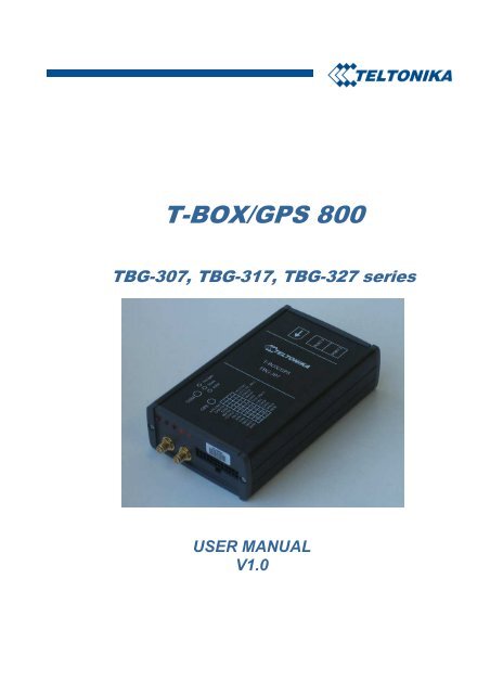
T-<strong>BOX</strong>/<strong>GPS</strong> <strong>800</strong><br />
TBG-307, TBG-317, TBG-327 series<br />
USER MANUAL<br />
V1.0
CONTENTS<br />
1. Short description ........................................................................................................................ 3<br />
2. Package contents........................................................................................................................ 4<br />
3. Main features ............................................................................................................................. 5<br />
4. Mechanical features ................................................................................................................... 6<br />
5. Connection & pinout.................................................................................................................. 7<br />
5.1 Socket 2×11 ....................................................................................................................... 7<br />
5.2 PORT 2 & PORT 3............................................................................................................ 8<br />
6. Internal architecture ................................................................................................................... 9<br />
6.1 TBG-307 series ................................................................................................................ 10<br />
6.2 TBG-317 series ................................................................................................................ 11<br />
6.3 TBG-327 series ................................................................................................................ 13<br />
7. Accesories................................................................................................................................ 14<br />
7.1 Voltage adjuster GCM-001.............................................................................................. 14<br />
7.1.1 Sample of how to use GCM-001 for fuel level measurement in the tank................ 16<br />
7.2 Temperature sensor TTJ-100 ........................................................................................... 17<br />
8. Communication protocols........................................................................................................ 18<br />
8.1 Power management command set.................................................................................... 18<br />
8.2 Event counter command set............................................................................................. 18<br />
8.3 RFID command set (Only TBG-317 series) .................................................................... 19<br />
8.4 Digital thermometers DS1820 command set ................................................................... 19<br />
8.5 Digital input command .................................................................................................... 19<br />
9. Technical support..................................................................................................................... 20<br />
10. Changes Log Sheet .............................................................................................................. 21<br />
1
T-<strong>BOX</strong>/<strong>GPS</strong> <strong>800</strong> USER MANUAL V1.0 2005<br />
This document reviews T-<strong>BOX</strong>/<strong>GPS</strong> <strong>800</strong> terminal features, architecture, application possibilities,<br />
interfaces and communication protocols.<br />
Series features<br />
TBG-307<br />
TBG-317<br />
TBG-327<br />
APLICOM 12 modem • • •<br />
<strong>GPS</strong> receiver • • •<br />
MCU • • •<br />
RFID reader<br />
•<br />
APLICOM 12 configurator port RS232 • • •<br />
APLICOM 12 extra communication port<br />
RS232<br />
APLICOM 12 and MCU communication<br />
by RS232<br />
MCU dynamic digital input (DMIN 1)<br />
MCU 1-WIRE® digital thermometer<br />
• •<br />
•<br />
•<br />
4 discrete inputs • • •<br />
4 discrete outputs • • •<br />
3 analogue inputs • • •<br />
•<br />
LEGAL NOTICE<br />
Copyright © 2005 <strong>Teltonika</strong><br />
All rights reserved. Reproduction, transfer, distribution or storage of part or all of the contents in<br />
this document in any form without the prior written permission of <strong>Teltonika</strong> is prohibited.<br />
Java and all Java based marks are trademarks or registered trademarks of Sun Microsystems, Inc.<br />
Other products and company names mentioned herein may be trademarks or trade names of their<br />
respective owners.<br />
2
1. SHORT DESCRIPTION<br />
T-Box/<strong>GPS</strong>-<strong>800</strong> is a terminal with GSM and <strong>GPS</strong> connectivity that is able to get device’s<br />
coordinates and transfer them via GSM network. This device is perfect for applications that need<br />
remote objects’ location acquirement. It is important to mention that T-Box/<strong>GPS</strong>-<strong>800</strong> has extra inputs<br />
and outputs allowing you to control and monitor other devices on remote objects. Apart from that, this<br />
device is fully programmable, so you can load a specific Java IMlet and adapt our device perfectly to<br />
match your needs.<br />
T-Box/<strong>GPS</strong>-<strong>800</strong> has integrated rechargeable Li-Ion battery and special controller for power<br />
management. This new feature enables <strong>GPS</strong>/GSM unit’s operation without using external power supply<br />
(up to 5 hours). Special power saving algorithm can be implemented using Java IMlet and device’s<br />
operation time can be expanded up to 3-5 times.<br />
3
2. PACKAGE CONTENTS<br />
MAIN PARTS<br />
1. T-Box/<strong>GPS</strong>-<strong>800</strong><br />
2. PC T-Box/<strong>GPS</strong>-<strong>800</strong> serial cable<br />
3. 2x11 plug with cables for power supply, inputs and outputs<br />
4. CD with Programming Software and User Manual<br />
5. Combined <strong>GPS</strong> and GSM antenna (optionally separate antennas may be ordered)<br />
6. RFID antenna (only with TBG-317 series)<br />
ACCESORIES<br />
7. Temperature sensors TTJ-100 (optional)<br />
8. Voltage adjuster GCM-001 (optional)<br />
4
3. MAIN FEATURES<br />
Make tracking of remote objects (trucks, cars, ships etc) fast and easy<br />
Device supports following GSM bearers:<br />
o EDGE class 2 (up to 118,4 kbps).<br />
o GPRS class 6 (up to 56-114 kbps).<br />
o HSCSD (up to 43,2 kbps).<br />
o CSD (up to 14,4 kbps).<br />
o SMS (text/data).<br />
o USSD (data).<br />
If most connectivity types are supported, you can choose one that suites you best according<br />
price, reliability, speed or ease of use.<br />
Dual-band:<br />
o European (and Asian) version - 900 MHz / 1<strong>800</strong> MHz.<br />
o American version - 850 MHz / 1900 MHz.<br />
Device’s aluminium case is very robust and suites perfectly for installation into harsh<br />
environment such as cars, trucks, boats or other moving objects.<br />
Internal rechargeable Li-Ion battery includes charge controller.<br />
T-Box/<strong>GPS</strong>-<strong>800</strong> has 4 digital inputs, 4 digital outputs and 3 analogue inputs that can be used to<br />
perform tasks on remote objects, such as monitoring fuel tank level, temperature, engine status,<br />
or checking truck door etc.<br />
T-Box/<strong>GPS</strong>-<strong>800</strong> is an open architecture device, which is fully programmable, so if you want to<br />
perform a very specific task, you can adapt device to match your needs by writing your own<br />
Java IMlet or asking our technical staff to make it for you. There also are TCP/IP and UDP<br />
stacks integrated.<br />
AutoPIN feature enters the PIN code each time the device is turned on, while SIM card is still<br />
protected with code.<br />
RFID tag detection (Only TBG-317 series).<br />
Combined GSM and <strong>GPS</strong> antenna saves space on vehicle.<br />
3 LED indicators: “Power”, “Status” and “Navigate”.<br />
An advanced solution for a reasonable price.<br />
5
4. MECHANICAL FEATURES<br />
Figure 1. T-Box/<strong>GPS</strong> <strong>800</strong> drawing & spec<br />
Dimensions in millimeters, tolerance ±0.5mm<br />
Part name Physical specification Technical details<br />
Navigation LED Red color LED<br />
Status LED<br />
Red color LED<br />
Power LED<br />
Red color LED<br />
Power supply 9-30 V DC<br />
RFID antenna connector SMA<br />
Energy consumption:<br />
RFID<br />
(Only TBG-317 series)<br />
Stand by mode 30 mA<br />
GSM GSM antenna connector SMA<br />
GPRS max RMS 590 mA, peak up to 2A<br />
<strong>GPS</strong> <strong>GPS</strong> antenna connector SMA<br />
Operating temperature: -25°C ÷ +55°C<br />
Socket 2×11 Molex Micro Fit (3.0) 43045-2221<br />
Storage temperature: -40°C ÷ +70°C<br />
SIM<br />
GSM SIM card socket<br />
Relative humidity 5÷95%<br />
PORT 2<br />
RJ45 8 pin socket<br />
PORT 3<br />
RJ45 8 pin socket<br />
6
5. CONNECTION & PINOUT<br />
5.1 Socket 2×11<br />
ACUM 2 2 1 ACUM 1<br />
OUT 9 4 3 + (10÷30) V<br />
GND 6 5 OUT 8<br />
OUT 6 8 7 OUT 7<br />
+5V OUT 10 9 GND<br />
AIN 3 12 11 EXT V<br />
AIN 1 14 13 AIN 2<br />
GND 16 15 GNDI<br />
DMIN 1 18 17 -<br />
IN 9 20 19 IN 10<br />
IN 7 22 21 IN 8<br />
Figure 2. 2×11 socket pinout<br />
Pin<br />
Nr.<br />
Pin Name<br />
Description<br />
1 2 3<br />
1 ACUM 1<br />
This pin is used connected with pin ACUM 2. Function of these pins –<br />
disconnect internal accumulator during shipment or storage. When<br />
ACUM 1 and ACUM 2 are connected internal accumulator is on, while<br />
disconnected internal accumulator is off.<br />
2 ACUM 2<br />
This pin is used connected with pin ACUM 1. Function of these pins –<br />
disconnect internal accumulator during shipment or storage. When<br />
ACUM 1 and ACUM 2 are connected internal accumulator is on, while<br />
disconnected internal accumulator is off.<br />
3 + (10÷30) V<br />
Modules power supply. Voltage range 10-30V DC. Power consumption<br />
in standby mode ~30mA@12V, peak up to 1000mA@12V<br />
4 OUT 9 Digital output. Channel 9. Open collector output. Max 500mA.<br />
5 OUT 8 Digital output. Channel 8. Open collector output. Max 500mA.<br />
6 GND Ground pin.<br />
7 OUT 7 Digital output. Channel 7. Open collector output. Max 500mA.<br />
8 OUT 6 Digital output. Channel 6. Open collector output. Max 500mA.<br />
9 GND Ground pin.<br />
10 +5V OUT +5V output for external devices. Max 100mA.<br />
11 EXT V<br />
External devices supply voltage. Outputs (pins 4, 5, 7, 8) have internal<br />
protection diodes in the case if output is hard inductive loaded.<br />
12 AIN 3 Analog input, channel 3. Input range: 0-2.8V<br />
13 AIN 2 Analog input, channel 2. Input range: 0-2.8V<br />
14 AIN 1 Analog input, channel 2. Input range: 0-2.8V<br />
15 GNDI Ground for digital inputs. Isolated from GND.<br />
16 GND Ground pin.<br />
7
1 2 3<br />
17 - -<br />
18 DMIN 1<br />
In T-<strong>BOX</strong>/<strong>GPS</strong> TBG 307 fast counter digital input, channel 1<br />
In T-<strong>BOX</strong>/<strong>GPS</strong> TBG 317 data input from Dallas DS 1820<br />
temperature sensors.<br />
In T-<strong>BOX</strong>/<strong>GPS</strong> TBG 327 doesn’t exist.<br />
19 IN 10 Digital input, channel 10. With galvanic isolation.<br />
20 IN 9 Digital input, channel 9. With galvanic isolation.<br />
21 IN 8 Digital input, channel 8. With galvanic isolation.<br />
22 IN 7 Digital input, channel 7. With galvanic isolation.<br />
5.2 PORT 2 & PORT 3<br />
RJ-45 socket PORT 2 PORT 3<br />
8 7 6 5 4 3 2 1<br />
Pin<br />
Pin<br />
Description<br />
Nr.<br />
Nr.<br />
Description<br />
1 - 1 -<br />
2 TXD_<strong>GPS</strong> 2 -<br />
3 - 3 -<br />
4 GND 4 GND<br />
5 RXD2 5 RXD3<br />
6 TXD2 6 TXD3<br />
7 CTS2 7 -<br />
8 RTS2 8 -<br />
8
6. INTERNAL ARCHITECTURE<br />
APLICOM 12 modem is equipped with J2ME virtual Java Machine. This platform can be used<br />
for different user applications. For further documentation of APLICOM 12 modem please contact<br />
APLICOM corp. (www.aplicom.com ).<br />
T-Box/<strong>GPS</strong>-<strong>800</strong> has special power management scheme and MCU to control power. It can<br />
charge internal battery and turn on or off all peripheral devices for desired period of time. For<br />
APLICOM 12 modem power control PORT3 is used. Command set can be found in chapter 8.1.<br />
Integrated Li-Ion rechargeable battery is able to supply power for 5 hours, (possible longer time; it<br />
depends on how frequently data is transmitted) if there is no external power supply. Its lifetime is<br />
more then 1000 charge – discharge cycles (withstands 1000 times by 5 hours without external power).<br />
Internal MCU has a special function. While APLICOM 12 module can’t guarantee real time<br />
operation with GIO, we have added event counter function in this module, using MCU. Digital input<br />
IN7 can be used as event counter. Using the PORT3 and a special protocol (chapter 8.2), counter can<br />
reset or read current event counter’s value.<br />
9
6.1 TBG-307 series<br />
OUT6<br />
OUT7<br />
OUT8<br />
OUT9<br />
IN7<br />
PORT 3<br />
RS232 TX<br />
IN8<br />
IN9<br />
IN10<br />
AIN1<br />
GSM<br />
antenna<br />
AIN2<br />
AIN3<br />
Aplicom 12<br />
GSM module<br />
PORT 3<br />
(RS232)<br />
MCU<br />
DMIN 1<br />
RXD2R<br />
TXD2R<br />
PORT 2<br />
(RS232)<br />
CTS2R<br />
RTS2R<br />
TXD_<strong>GPS</strong>R<br />
Power<br />
management<br />
DC power<br />
supply<br />
<strong>GPS</strong><br />
antenna<br />
<strong>GPS</strong><br />
receiver<br />
Backup<br />
battery<br />
Figure 3. TBG-307 series T-Box/<strong>GPS</strong> internal architecture<br />
10
6.2 TBG-317 series<br />
OUT6<br />
OUT7<br />
OUT8<br />
OUT9<br />
IN7<br />
IN8<br />
IN9<br />
RFID<br />
reader<br />
IN10<br />
AIN1<br />
GSM<br />
antenna<br />
AIN2<br />
AIN3<br />
Aplicom 12<br />
GSM module<br />
PORT 3<br />
(RS232)<br />
MCU<br />
RXD2R<br />
TXD2R<br />
PORT 2<br />
(RS232)<br />
PORT 3<br />
RS232 TX<br />
RFID<br />
antenna<br />
DMIN 1<br />
CTS2R<br />
RTS2R<br />
TXD_<strong>GPS</strong>R<br />
Power<br />
management<br />
DC power<br />
supply<br />
<strong>GPS</strong><br />
antenna<br />
<strong>GPS</strong><br />
receiver<br />
Backup<br />
battery<br />
Figure 4. TBG-317 series T-Box/<strong>GPS</strong> internal architecture<br />
Only in T-Box/<strong>GPS</strong> <strong>800</strong> TBG-317 series is integrated RFID reader (Wavetrend L-RM101 RF<br />
Receiver Module).<br />
Also it is possible to connect up to 5 digital thermometers DS1820 through DMIN 1. These<br />
digital thermometers are made 1-WIRE® technology. Please see connection scheme in fig.5.<br />
11
T-<strong>BOX</strong>/<strong>GPS</strong> module<br />
Socket 2×11<br />
GND<br />
DMIN 1<br />
Pin 16<br />
GND<br />
DATA<br />
+5V OUT<br />
Pin 18<br />
+5V<br />
Pin 10<br />
DQ<br />
V DD<br />
Digital<br />
thermometer<br />
(DS1820)<br />
GND<br />
...<br />
U to 5 thermometers<br />
...<br />
...<br />
V DD<br />
DQ<br />
Digital<br />
thermometer<br />
(DS1820)<br />
GND<br />
Figure 5. Digital thermometers DS1820 connection scheme<br />
12
6.3 TBG-327 series<br />
OUT6<br />
OUT7<br />
OUT8<br />
OUT9<br />
IN7<br />
IN8<br />
IN9<br />
PORT 3<br />
(RS232)<br />
IN10<br />
AIN1<br />
GSM<br />
antenna<br />
AIN2<br />
AIN3<br />
Aplicom 12<br />
GSM module<br />
MCU<br />
RXD2R<br />
TXD2R<br />
PORT 2<br />
(RS232)<br />
CTS2R<br />
RTS2R<br />
TXD_<strong>GPS</strong>R<br />
Power<br />
management<br />
DC power<br />
supply<br />
<strong>GPS</strong><br />
antenna<br />
<strong>GPS</strong><br />
receiver<br />
Backup<br />
battery<br />
Figure 6. TBG-327 series T-Box/<strong>GPS</strong> internal architecture<br />
This series module has extra RS232 connection slot, which can be used for external devices’<br />
connections (for example BAR code reader or else).<br />
13
7. ACCESORIES<br />
JSC <strong>Teltonika</strong> offers accessories that make adjustment of temperature sensors and sensors<br />
connected to T-Box/<strong>GPS</strong> analogue inputs simpler.<br />
7.1 Voltage adjuster GCM-001<br />
Maximum voltage of analogue T-Box/<strong>GPS</strong> input is 2.8 Volts. Some of sensors output voltage is<br />
higher. To make connection of such sensor possible, voltage adjuster GCM-001 that proportionally<br />
converts voltage has been created.<br />
Power<br />
LED<br />
59 28<br />
Output<br />
socket<br />
6<br />
7<br />
8<br />
9<br />
10<br />
1<br />
2<br />
3<br />
4<br />
5<br />
Input<br />
socket<br />
77<br />
105<br />
Dimensions in millimetres, tolerance ±1mm<br />
Figure 7. GCM-001 dimensions & spec.<br />
It has three independent channels, so it is possible to adjust three sensors using one device.<br />
Also the device has +5 Volts output, which can be useful for some sensors.<br />
Main features:<br />
Supply voltage (Vpp) DC +9 ÷ 30 V<br />
Input voltage range (0 ÷ 27 Volts)<br />
Output voltage range (0 ÷ 2.8 Volts)<br />
14
Voltage adjustment is executed by choosing right divisor (placing jumper in one of the four<br />
positions). Twisting amplifier’s potentiometer performs precise adjustment. (Please check fig.8.).<br />
+5V OUT<br />
6<br />
DC/DC<br />
converter<br />
Vpp<br />
1<br />
7<br />
GND<br />
GND<br />
2<br />
8<br />
OUTPUT 1<br />
Channel 1<br />
INPUT 1<br />
3<br />
Adjustable<br />
amplifier<br />
×1 – ×28<br />
Adjustable<br />
amplifier<br />
×1 – ×28<br />
Divisor<br />
×0.1<br />
Divisor<br />
×0.19<br />
Divisor<br />
×0.31<br />
9<br />
10<br />
OUTPUT 2<br />
OUTPUT 3<br />
...<br />
...<br />
Functional scheme<br />
Channel 2<br />
Channel 3<br />
INPUT 2<br />
INPUT 3<br />
4<br />
5<br />
Divisors pins<br />
(to connect with<br />
jumpers)<br />
Mechanical scheme<br />
(PCB top view)<br />
Figure 8. GCM-001 functional and mechanical adjustment scheme<br />
15
7.1.1 Sample of how to use GCM-001 for fuel level measurement in the tank<br />
Most cars have fuel tank level sensors, which approximately show fuel level in indicators panel. It<br />
is possible to connect T-Box/<strong>GPS</strong> using GCM-001 voltage adjuster to get real-time data about fuel<br />
level in the tank (if sensor renders analogue signal proportional to fuel level)<br />
+12V<br />
Part of the car<br />
T-Box/<strong>GPS</strong><br />
AIN 1<br />
Fig.9 describes connection scheme to the<br />
T-Box/<strong>GPS</strong>. After connecting tank fuel level<br />
sensor, please calibrate GCM-001 (adjust so,<br />
that if tank is full, output 1 voltage is 2.8<br />
Volts). T-Box/<strong>GPS</strong> starts registering this<br />
parameter and is able to inform user about its<br />
value.<br />
Input 1 GCM-001 Output 1<br />
Voltage adjuster<br />
TANK FUEL<br />
LEVEL<br />
SENSOR<br />
Figure 9. GCM-001 connection to fuel sensor scheme<br />
16
7.2 Temperature sensor TTJ-100<br />
To simplify thermometer mounting in the object, it is placed on PCB and inserted into box.<br />
System integrator should solder the T-Box/<strong>GPS</strong> wires to PCB and put the sensor in place, which<br />
temperature is important.<br />
Ø7.5<br />
2 holes<br />
46<br />
13.5<br />
31<br />
2<br />
Dimensions in millimetres, tolerance ±1mm<br />
Figure 10. TTj-100 dimensions & spec.<br />
In TTJ-100 is used Dallas digital thermometer DS1820. It is possible to join up to 5<br />
thermometers parallel with each other and measure the temperature in 5 places on the object (see<br />
chapter 6.2). The picture bellow describes pinout of the TTJ-100.<br />
Left row of pins<br />
Right row of pins<br />
Connected via<br />
100 Ohm to 1 on<br />
the right row<br />
Connected to 4<br />
on the right row.<br />
1<br />
2<br />
1<br />
2<br />
4<br />
3<br />
2<br />
1<br />
Connected to pin 2<br />
4<br />
on the left row<br />
3 GND<br />
2 Data (to DMIN 1)<br />
1 Vpp (+5 Volts DC)<br />
17
8. COMMUNICATION PROTOCOLS<br />
For communication between APLICOM 12 modem, MCU, <strong>GPS</strong> module and RFID receiver<br />
ModBus protocol is applied. All possible commands are listed in the tables below.<br />
8.1 Power management command set<br />
Name Code Parameter Description Answer Description<br />
Get power supply<br />
state<br />
Enter power save<br />
state<br />
Get power supply<br />
voltage<br />
Get battery<br />
voltage<br />
Get battery<br />
charge current<br />
Get status of <strong>GPS</strong><br />
antenna power<br />
supply<br />
Temperature of<br />
battery<br />
Battery charge<br />
ON/OFF<br />
Power down<br />
mode<br />
0x06 - -<br />
0x07 0-59<br />
Time in<br />
minutes<br />
1 symbol. - 0,<br />
1, 2, 3, 4<br />
2 symbol. –<br />
last charge<br />
time (min)<br />
0x09 - - 0-29000<br />
0 – external power supply<br />
OK, battery charged<br />
1 – battery is charging<br />
2 – power supply is from<br />
battery<br />
3 – accumulator discharged<br />
4 – charge error<br />
- -<br />
Power supply voltage in<br />
mV*<br />
0x0A - - 0-10000 Battery voltage in mV<br />
0x0B - - 0-1294<br />
0x0D - - 0, 1, 2<br />
Battery charge current in<br />
mA<br />
0 – normal state<br />
1 – short circuit<br />
2 – not plugged<br />
0x0E - - 1 byte Temperature in 0 C<br />
0x11 0-1 - -<br />
0x20 - - -<br />
0 – Battery charge ON<br />
1 – Battery charge OFF<br />
If module has no external<br />
voltage supply, it switches<br />
the module off.<br />
8.2 Event counter command set<br />
Name Code Parameter Description Answer Description<br />
Read value of<br />
counter (DMIN 1)<br />
Turn off counter<br />
(DMIN 1)<br />
0x12 - - 4 bytes<br />
0x13 - - -<br />
Unsigned long – value of<br />
counter<br />
* - Real voltage on power supply is higher then answers of command 0x09 by 0.7 Volts. It is so, because of protection<br />
diode on power supply pin.<br />
18
8.3 RFID command set (Only TBG-317 series)<br />
Name Code Parameter Description Answer Description<br />
Write to RFID<br />
Read from RFID<br />
0x0F<br />
0x10<br />
Command,<br />
Value<br />
Command,<br />
Value<br />
- - -<br />
-<br />
Array was<br />
read from<br />
RFID<br />
To use rest of RFID functions please contact “Wavetrend Technologies” (www.wavetrend.net ) to<br />
get specification of L-RM101 RF Receiver Module with command set.<br />
-<br />
8.4 Digital thermometers DS1820 command set<br />
Name Code Parameter Description Answer Description<br />
Calculate existing<br />
sensors<br />
Read sensor data<br />
Sensors initialise<br />
0x14<br />
0x15<br />
0x16<br />
Sensor<br />
number<br />
Number of<br />
sensors, 1<br />
symbol<br />
Temperature,<br />
2 symbols<br />
Number of<br />
sensors;<br />
1 symbol<br />
If answers 0xF000 it means<br />
error in temperature read<br />
Calculating sensors, and<br />
attaching ID (0, 1, 2, 3, 4)<br />
For more detail information please check “Dallas Semiconductors” digital thermometer<br />
DS1820 specification.<br />
8.5 Digital input command<br />
Name Code Parameter Description Answer Description<br />
Read digital input<br />
status<br />
0x14 0-1<br />
1 byte. Input<br />
index<br />
0, 1 Logic input status<br />
19
9. TECHNICAL SUPPORT<br />
If you encountered any problems while using our products, please contact our technical support<br />
by sending an e-mail to support@teltonika.lt . We will be glad to help you.<br />
If you are interested in other <strong>Teltonika</strong> products, please visit our website www.teltonika.lt , where<br />
you will find our latest products.<br />
If you are interested in product pricing or if you would like to order our products with other<br />
antennas, connectors or built-in programs, please contact our sales department by sending an e-mail to<br />
sales@teltonika.lt .<br />
20
10.CHANGES LOG SHEET<br />
Nr.<br />
Date<br />
New<br />
version<br />
number<br />
Comments<br />
21


