Pump Primer 1 $100 - 8 Hours - Technical Learning College
Pump Primer 1 $100 - 8 Hours - Technical Learning College
Pump Primer 1 $100 - 8 Hours - Technical Learning College

Create successful ePaper yourself
Turn your PDF publications into a flip-book with our unique Google optimized e-Paper software.
PUMP PRIMER 1<br />
CONTINUING EDUCATION<br />
PROFESSIONAL DEVELOPMENT COURSE
Printing and Saving Instructions<br />
The best thing to do is to download this pdf document to your computer<br />
desktop and open it with Adobe Acrobat reader.<br />
Abode Acrobat reader is a free computer software program and you can<br />
find it at Abode Acrobat’s website.<br />
You can complete the course by viewing the course materials on your<br />
computer or you can print it out. We give you permission to print this<br />
document.<br />
Printing Instructions: If you are going to print this document, this<br />
document is designed to be printed double-sided or duplexed but can be<br />
single-sided.<br />
This course booklet does not have the assignment. Please visit our<br />
website and download the assignment also.<br />
Link to Assignment…<br />
http://www.tlch2o.com/PDF/<strong>Pump</strong><strong>Primer</strong>1Ass.pdf<br />
State Approval Listing Link, check to see if your State accepts or has<br />
pre-approved this course. Not all States are listed. Not all courses are<br />
listed. If the course is not accepted for CEU credit, we will give you the<br />
course free if you ask your State to accept it for credit.<br />
Professional Engineers; Most states will accept our courses for credit but<br />
we do not officially list the States or Agencies.<br />
State Approval Listing URL…<br />
http://www.tlch2o.com/PDF/CEU%20State%20Approvals.pdf<br />
You can obtain a printed version from TLC for an additional $49.95 plus<br />
shipping charges.<br />
<strong>Pump</strong> <strong>Primer</strong> I Course © 12/1/2012 (866) 557-1746 www.ABCTLC.com<br />
2
Important Information about this Manual<br />
This manual has been prepared to educate operators in the general education of pumping,<br />
pumps, motors, and hydraulic principles including basic water training and different pump<br />
applications. For most students, the study of pumping and hydraulics is quite large, requiring a<br />
major effort to bring it under control.<br />
This manual should not be used as a guidance document for employees who are involved with<br />
cross-connection control. It is not designed to meet the requirements of the United States<br />
Environmental Protection Agency (EPA), the Department of Labor-Occupational Safety and<br />
Health Administration (OSHA), or your state environmental or health agency. <strong>Technical</strong><br />
<strong>Learning</strong> <strong>College</strong> or <strong>Technical</strong> <strong>Learning</strong> Consultants, Inc. makes no warranty, guarantee or<br />
representation as to the absolute correctness or appropriateness of the information in this<br />
manual and assumes no responsibility in connection with the implementation of this information.<br />
It cannot be assumed that this manual contains all measures and concepts required for specific<br />
conditions or circumstances. This document should be used for educational purposes and is<br />
not considered a legal document. Individuals who are responsible for hydraulic equipment,<br />
cross-connection control, backflow prevention or water distribution should obtain and comply<br />
with the most recent federal, state, and local regulations relevant to these sites and are urged to<br />
consult with OSHA, the EPA and other appropriate federal, state and local agencies.<br />
Copyright Notice<br />
©2005 <strong>Technical</strong> <strong>Learning</strong> <strong>College</strong> (TLC) No part of this work may be reproduced or<br />
distributed in any form or by any means without TLC’s prior written approval. Permission<br />
has been sought for all images and text where we believe copyright exists and where the<br />
copyright holder is traceable and contactable. All material that is not credited or<br />
acknowledged is the copyright of <strong>Technical</strong> <strong>Learning</strong> <strong>College</strong>. This information is intended<br />
for educational purposes only. Most unaccredited photographs have been taken by TLC<br />
instructors or TLC students. We will be pleased to hear from any copyright holder and will<br />
make good on your work if any unintentional copyright infringements were made as soon as<br />
these issues are brought to the editor's attention.<br />
Every possible effort is made to ensure that all information provided in this course is<br />
accurate. All written, graphic, photographic or other material is provided for information only.<br />
Therefore, <strong>Technical</strong> <strong>Learning</strong> <strong>College</strong> accepts no responsibility or liability whatsoever for<br />
the application or misuse of any information included herein. Requests for permission to<br />
make copies should be made to the following address:<br />
TLC<br />
PO Box 420<br />
Payson, AZ 85547-0420<br />
Information in this document is subject to change without notice. TLC is not liable for errors<br />
or omissions appearing in this document.<br />
<strong>Pump</strong> <strong>Primer</strong> I Course © 12/1/2012 (866) 557-1746 www.ABCTLC.com<br />
3
Contributing Editors<br />
Joseph Camerata has a BS in Management with honors (magna cum laude). He retired as<br />
a Chemist in 2006 having worked in the field of chemical, environmental, and industrial<br />
hygiene sampling and analysis for 40 years. He has been a professional presenter at an<br />
EPA analytical conference at the Biosphere in Arizona and a presenter at an AWWA<br />
conference in Mesa, Arizona. He also taught safety classes at the Honeywell and City of<br />
Phoenix, and is a motivational/inspirational speaker nationally and internationally.<br />
Dr. Eric Pearce S.M.E., chemistry and biological review.<br />
Dr. Pete Greet S.M.E., retired biology instructor.<br />
Jack White, Environmental, Health, Safety expert, City of Phoenix. Art Credits.<br />
<strong>Pump</strong> <strong>Primer</strong> I Course © 12/1/2012 (866) 557-1746 www.ABCTLC.com<br />
4
<strong>Technical</strong> <strong>Learning</strong> <strong>College</strong>’s Scope and Function<br />
<strong>Technical</strong> <strong>Learning</strong> <strong>College</strong> (TLC) offers affordable continuing education for today’s working<br />
professionals who need to maintain licenses or certifications. TLC holds approximately<br />
eighty different governmental approvals for granting of continuing education credit.<br />
TLC’s delivery method of continuing education can include traditional types of classroom<br />
lectures and distance-based courses or independent study. Most of TLC’s distance based or<br />
independent study courses are offered in a print based format and you are welcome to<br />
examine this material on your computer with no obligation. Our courses are designed to be<br />
flexible and for you do finish the material on your leisure. Students can also receive course<br />
materials through the mail. The CEU course or e-manual will contain all your lessons,<br />
activities and assignments. Most CEU courses allow students to submit lessons using e-mail<br />
or fax, however some courses require students to submit lessons by postal mail. (See the<br />
course description for more information.) Students have direct contact with their instructor—<br />
primarily by e-mail. TLC’s CEU courses may use such technologies as the World Wide Web,<br />
e-mail, CD-ROMs, videotapes and hard copies. (See the course description.) Make sure you<br />
have access to the necessary equipment before enrolling, i.e., printer, Microsoft Word<br />
and/or Adobe Acrobat Reader. Some courses may require proctored exams depending<br />
upon your state requirements.<br />
Flexible <strong>Learning</strong><br />
At TLC, there are no scheduled online sessions you need contend with, nor are you required<br />
to participate in learning teams or groups designed for the "typical" younger campus based<br />
student. You will work at your own pace, completing assignments in time frames that work<br />
best for you. TLC's method of flexible individualized instruction is designed to provide each<br />
student the guidance and support needed for successful course completion.<br />
We will beat any other training competitor’s price for the same CEU material or classroom<br />
training. Student satisfaction is guaranteed.<br />
Course Structure<br />
TLC's online courses combine the best of online delivery and traditional university textbooks.<br />
Online you will find the course syllabus, course content, assignments, and online open book<br />
exams. This student friendly course design allows you the most flexibility in choosing when<br />
and where you will study.<br />
Classroom of One<br />
TLC Online offers you the best of both worlds. You learn on your own terms, on your own<br />
time, but you are never on your own. Once enrolled, you will be assigned a personal<br />
Student Service Representative who works with you on an individualized basis throughout<br />
your program of study. Course specific faculty members are assigned at the beginning of<br />
each course providing the academic support you need to successfully complete each<br />
course.<br />
Satisfaction Guaranteed<br />
Our Iron-Clad, Risk-Free Guarantee ensures you will be another satisfied TLC student. We<br />
have many years of experience, dealing with thousands of students. We assure you, our<br />
customer satisfaction is second to none.<br />
<strong>Pump</strong> <strong>Primer</strong> I Course © 12/1/2012 (866) 557-1746 www.ABCTLC.com<br />
5
This is one reason we have taught more than 20,000 students.<br />
Our administrative staff is trained to provide outstanding customer service. Part of that training<br />
is knowing how to solve most problems on the spot.<br />
TLC Continuing Education Course Material Development<br />
<strong>Technical</strong> <strong>Learning</strong> <strong>College</strong>’s (TLC’s) continuing education course material development was<br />
based upon several factors; extensive academic research, advice from subject matter experts,<br />
data analysis, task analysis and training needs assessment process information gathered from<br />
other states.<br />
Most of our students will complete the Word version of the assignment and when<br />
finished, simply e-mail it to us. Make sure you include the registration page. Give us<br />
about two weeks to grade it and mail you a certificate of completion.<br />
Rush Service<br />
If you need the assignment graded within 48 hours, prepare to pay an additional rush<br />
service fee of $50.00 for processing.<br />
<strong>Pump</strong> <strong>Primer</strong> I Course © 12/1/2012 (866) 557-1746 www.ABCTLC.com<br />
6
Course Description<br />
<strong>Pump</strong> <strong>Primer</strong> I Training Course<br />
This short CEU course will review various hydraulic principles and basic pumping foundations to<br />
properly understand the operation and function of primary water/wastewater related pumps and<br />
equipment. You will not need any other materials for this course.<br />
Water Distribution, Well Drillers, <strong>Pump</strong> Installers, Water Treatment Operators,<br />
Wastewater Treatment Operators, Wastewater Collection Operators, Industrial<br />
Wastewater Operators and General Backflow Assembly Testers. The target audience for<br />
this course is the person interested in working in a water or wastewater treatment or<br />
distribution/collection facility and/or wishing to maintain CEUs for certification license or to learn<br />
how to do the job safely and effectively, and/or to meet education needs for promotion.<br />
Final Examination for Credit<br />
Opportunity to pass the final comprehensive examination is limited to three attempts per course<br />
enrollment.<br />
Course Procedures for Registration and Support<br />
All of <strong>Technical</strong> <strong>Learning</strong> <strong>College</strong>’s correspondence courses have complete registration and<br />
support services offered. Delivery of services will include, e-mail, web site, telephone, fax and<br />
mail support. TLC will attempt immediate and prompt service.<br />
When a student registers for a distance or correspondence course, he/she is assigned a start<br />
date and an end date. It is the student's responsibility to note dates for assignments and keep<br />
up with the course work. If a student falls behind, he/she must contact TLC and request an end<br />
date extension in order to complete the course. It is the prerogative of TLC to decide whether to<br />
grant the request. All students will be tracked by their social security number or a unique<br />
number will be assigned to the student.<br />
Instructions for Assignment<br />
The <strong>Pump</strong> <strong>Primer</strong> I - 0.8 CEU training course training course uses a multiple choice type<br />
answer key. You can find a copy of the answer key r in Word format on TLC’s website under the<br />
Assignment Page. You can also find complete course support under the Assignment Page.<br />
You can write your answers in this manual or type out your own answer key. TLC would prefer<br />
that you type out and fax or e-mail the final exam to TLC, but it is not required.<br />
Feedback Mechanism (examination procedures)<br />
Each student will receive a feedback form as part of their study packet. You will be able to find<br />
this form in the rear of the course or lesson.<br />
Security and Integrity<br />
All students are required to do their own work. All lesson sheets and final exams are not<br />
returned to the student to discourage sharing of answers. Any fraud or deceit and the student<br />
will forfeit all fees and the appropriate agency will be notified.<br />
<strong>Pump</strong> <strong>Primer</strong> I Course © 12/1/2012 (866) 557-1746 www.ABCTLC.com<br />
7
Grading Criteria<br />
TLC will offer the student either pass/fail or a standard letter grading assignment. If TLC is not<br />
notified, you will only receive a pass/fail notice.<br />
Required Texts<br />
The <strong>Pump</strong> <strong>Primer</strong> I - 0.8 CEU training course will not require any other materials. This course<br />
comes complete. No other materials are needed.<br />
Recordkeeping and Reporting Practices<br />
TLC will keep all student records for a minimum of seven years. It is your responsibility to give<br />
the completion certificate to the appropriate agencies.<br />
ADA Compliance<br />
TLC will make reasonable accommodations for persons with documented disabilities. Students<br />
should notify TLC and their instructors of any special needs. Course content may vary from this<br />
outline to meet the needs of this particular group. Please check with your State for special<br />
instructions.<br />
You will have 90 days from receipt of this manual to complete it in order to receive your<br />
Continuing Education Units (CEUs) or Professional Development <strong>Hours</strong> (PDHs). A score of<br />
70% or better is necessary to pass this course. If you should need any assistance, please email<br />
all concerns and the final test to: info@tlch2o.com.<br />
When the Student finishes this course…<br />
At the conclusion of this course:<br />
At the finish of this course, the student should be able to explain and describe the various<br />
hydraulic principles, pumping devices, and pumping methods, identify various hydraulic and<br />
horsepower principles that are commonly employed in moving fluids. Upon completion of this<br />
course, the student will obtain 8 hours of continuing education relating to pump, pumping and<br />
hydraulic principles.<br />
Educational Mission<br />
The educational mission of TLC is:<br />
To provide TLC students with comprehensive and ongoing training in the theory and skills<br />
needed for the environmental education field,<br />
To provide TLC students opportunities to apply and understand the theory and skills needed for<br />
operator certification and environmental education,<br />
To provide opportunities for TLC students to learn and practice environmental educational skills<br />
with members of the community for the purpose of sharing diverse perspectives and<br />
experience,<br />
To provide a forum in which students can exchange experiences and ideas related to<br />
environmental education,<br />
To provide a forum for the collection and dissemination of current information related to<br />
environmental education, and to maintain an environment that nurtures academic and personal<br />
growth.<br />
<strong>Pump</strong> <strong>Primer</strong> I Course © 12/1/2012 (866) 557-1746 www.ABCTLC.com<br />
8
Table of Contents<br />
Common Hydraulic Terms…………. 10<br />
<strong>Pump</strong> Definitions…………………… 11<br />
Archimedes…………. …………….. 13<br />
Hydraulic Principles…………. ……. 17<br />
Geometric Principles …………….. 22<br />
Atmospheric Pressure…………….. 23<br />
Pressure and Force…………. ……. 25<br />
Hydraulic Development……………. 27<br />
Hydraulic Lever…………………….. 30<br />
Forces on a Submerged Surface….. 34<br />
Hydrostatic Paradox……………….. 35<br />
Variations………….…………. ……. 38<br />
Pascal’s Law………….…………….. 39<br />
Venturi ………….…………………… 43<br />
<strong>Pump</strong> Introductions………………… 45<br />
Completed <strong>Pump</strong>s………….……… 47<br />
Types of <strong>Pump</strong>s………….………… 50<br />
General <strong>Pump</strong>ing Fundamentals……51<br />
<strong>Pump</strong>ing Categories………………… 52<br />
Positive Displacement <strong>Pump</strong>s…… 53<br />
<strong>Pump</strong> Specifications………………. 55<br />
Suction Lift………….………………. 56<br />
<strong>Pump</strong> Efficiency………….…………. 57<br />
<strong>Pump</strong>ing Requirements………….… 61<br />
<strong>Pump</strong> Viscosity………….…………. 63<br />
Darcy-Weisbach Formula…………. 66<br />
Types of <strong>Pump</strong>s…………………… 69<br />
Progressing Cavity <strong>Pump</strong>…………. 79<br />
Screw <strong>Pump</strong> ………….……………. 83<br />
Reciprocating <strong>Pump</strong>………….…… 85<br />
Rope <strong>Pump</strong> ………….…………. 93<br />
Impulse <strong>Pump</strong> ………….…………. 97<br />
Hydraulic Ram <strong>Pump</strong> ……………. 98<br />
Wind Mills………….………………. 103<br />
Pasture <strong>Pump</strong>s………….…………. 104<br />
Reciprocating <strong>Pump</strong>s……………… 113<br />
Vapor Pressure……………………. 120<br />
Sling <strong>Pump</strong>………….………………. 123<br />
Submersible………….……………… 124<br />
Valveless <strong>Pump</strong>s………….…………. 125<br />
Glossary………….………………….. 129<br />
Appendixes…………. ………………. 171<br />
References…………. ………………. 193<br />
<strong>Pump</strong> <strong>Primer</strong> I Course © 12/1/2012 (866) 557-1746 www.ABCTLC.com<br />
9
Common Hydraulic Terms<br />
Head<br />
The height of a column or body of fluid above a given point expressed in linear units.<br />
Head is often used to indicate gauge pressure. Pressure is equal to the height times the<br />
density of the liquid.<br />
Head, Friction<br />
The head required to overcome the friction at the interior surface of a conductor and<br />
between fluid particles in motion. It varies with flow, size, type, and conditions of<br />
conductors and fittings, and the fluid characteristics.<br />
Head, static<br />
The height of a column or body of fluid above a given point.<br />
Hydraulics<br />
Engineering science pertaining to liquid pressure and flow.<br />
Hydrokinetics<br />
Engineering science pertaining to the energy of liquid flow and pressure.<br />
Pascal's Law<br />
A pressure applied to a confined fluid at rest is transmitted with equal intensity<br />
throughout the fluid.<br />
Pressure<br />
The application of continuous force by one body upon another that it is touching;<br />
compression. Force per unit area, usually expressed in pounds per square inch (Pascal<br />
or bar).<br />
Pressure, Absolute<br />
The pressure above zone absolute, i.e. the sum of atmospheric and gauge pressure. In<br />
vacuum related work it is usually expressed in millimeters of mercury. (mmHg).<br />
Pressure, Atmospheric<br />
Pressure exported by the atmosphere at any specific location. (Sea level pressure is<br />
approximately 14.7 pounds per square inch absolute, 1 bar = 14.5psi.)<br />
Pressure, Gauge<br />
Pressure differential above or below ambient atmospheric pressure.<br />
Pressure, Static<br />
The pressure in a fluid at rest.<br />
<strong>Pump</strong> <strong>Primer</strong> I Course © 12/1/2012 (866) 557-1746 www.ABCTLC.com<br />
10
<strong>Pump</strong> Definitions (Larger Glossary in the rear of this manual)<br />
Fluid: Any substance that can be pumped such as oil, water, refrigerant, or even air.<br />
Gasket: Flat material that is compressed between two flanges to form a seal.<br />
Gland follower: A bushing used to compress the packing in the stuffing box and to control<br />
leakoff.<br />
Gland sealing line: A line that directs sealing fluid to the stuffing box.<br />
Horizontal pumps: <strong>Pump</strong>s in which the center line of the shaft is horizontal.<br />
Impeller: The part of the pump that increases the speed of the fluid being handled.<br />
Inboard: The end of the pump closest to the motor.<br />
Inter-stage diaphragm: A barrier that separates stages of a multi-stage pump.<br />
Key: A rectangular piece of metal that prevents the impeller from rotating on the shaft.<br />
Keyway: The area on the shaft that accepts the key.<br />
Kinetic energy: Energy associated with motion.<br />
Lantern ring: A metal ring located between rings of packing that distributes gland sealing fluid.<br />
Leak-off: Fluid that leaks from the stuffing box.<br />
Mechanical seal: A mechanical device that seals the pump stuffing box.<br />
Mixed flow pump: A pump that uses both axial-flow and radial-flow components in one<br />
impeller.<br />
Multi-stage pumps: <strong>Pump</strong>s with more than one impeller.<br />
Outboard: The end of the pump farthest from the motor.<br />
Packing: Soft, pliable material that seals the stuffing box.<br />
Positive displacement pumps: <strong>Pump</strong>s that move fluids by physically displacing the fluid inside<br />
the pump.<br />
Radial bearings: Bearings that prevent shaft movement in any direction outward from the center<br />
line of the pump.<br />
Radial flow: Flow at 90° to the center line of the shaft.<br />
Retaining nut: A nut that keeps the parts in place.<br />
<strong>Pump</strong> <strong>Primer</strong> I Course © 12/1/2012 (866) 557-1746 www.ABCTLC.com<br />
11
Rotor: The rotating parts, usually including the impeller, shaft, bearing housings, and all other<br />
parts included between the bearing housing and the impeller.<br />
Score: To cause lines, grooves, or scratches.<br />
Shaft: A cylindrical bar that transmits power from the driver to the pump impeller.<br />
Shaft sleeve: A replaceable tubular covering on the shaft.<br />
Shroud: The metal covering over the vanes of an impeller.<br />
Slop drain: The drain from the area that collects leak-off from the stuffing box.<br />
Slurry: A thick, viscous fluid, usually containing small particles.<br />
Stages: Impellers in a multi-stage pump.<br />
Stethoscope: A metal device that can amplify and pinpoint pump sounds.<br />
Strainer: A device that retains solid pieces while letting liquids through.<br />
Stuffing box: The area of the pump where the shaft penetrates the casing.<br />
Suction: The place where fluid enters the pump.<br />
Suction eye: The place where fluid enters the pump impeller.<br />
Throat bushing: A bushing at the bottom of the stuffing box that prevents packing from being<br />
pushed out of the stuffing box into the suction eye of the impeller.<br />
Thrust: Force, usually along the center line of the pump.<br />
Thrust bearings: Bearings that prevent shaft movement back and forth in the same direction as<br />
the center line of the shaft.<br />
Troubleshooting: Locating a problem.<br />
Vanes: The parts of the impeller that push and increase the speed of the fluid in the pump.<br />
Vertical pumps: <strong>Pump</strong>s in which the center line of the shaft runs vertically.<br />
Volute: The part of the pump that changes the speed of the fluid into pressure.<br />
Wearing rings: Replaceable rings on the impeller or the casing that wear as the pump operates.<br />
<strong>Pump</strong> <strong>Primer</strong> I Course © 12/1/2012 (866) 557-1746 www.ABCTLC.com<br />
12
Archimedes<br />
<strong>Pump</strong> <strong>Primer</strong> I Course © 12/1/2012 (866) 557-1746 www.ABCTLC.com<br />
13
Archimedes<br />
Born<br />
Died<br />
Education<br />
Family<br />
Inventions<br />
Fields of<br />
Science<br />
Initiated<br />
Major<br />
Writings<br />
Place in<br />
History<br />
About 287 BC in Syracuse, Sicily. At the time, Syracuse was an independent<br />
Greek city-state with a 500-year history.<br />
212 or 211 BC in Syracuse when it was being sacked by a Roman army. He was<br />
killed by a Roman soldier who did not know who he was.<br />
Probably studied in Alexandria, Egypt, under the followers of Euclid.<br />
His father was an astronomer named Phidias and he was probably related to<br />
Hieron II, the king of Syracuse. It is not known whether he was married nor had<br />
any children.<br />
Many war machines used in the defense of Syracuse, compound pulley systems,<br />
planetarium, water screw (possibly), water organ (possibly), burning mirrors (very<br />
unlikely).<br />
Hydrostatics, static mechanics, pycnometry (the measurement of the volume or<br />
density of an object). He is called the "father of integral calculus" and also the<br />
"father of mathematical physics".<br />
On plane equilibriums, Quadrature of the parabola, On the sphere and cylinder, On<br />
spirals, On conoids and spheroids, On floating bodies, Measurement of a circle,<br />
The Sand reckoner, On the method of mechanical problems.<br />
Generally regarded as the greatest mathematician and scientist of antiquity and<br />
one of the three greatest mathematicians of all time (together with Isaac Newton<br />
(English 1643-1727) and Carl Friedrich Gauss (German 1777-1855)).<br />
Archimedes was a great mathematician of ancient times. His greatest contributions were in<br />
geometry. He also spent some time in Egypt, where he invented the machine now called<br />
Archimedes' screw, which was a mechanical water pump. Among his most famous works is<br />
Measurement of the Circle, where he determined the exact value of pi between the two<br />
fractions, 3 10/71 and 3 1/7. He got this information by inscribing and circumscribing a circle<br />
with a 96-sided regular polygon.<br />
Archimedes made many contributions to geometry in his work in the areas of plane figures and<br />
in the areas of area and volumes of curved surfaces. His methods started the idea for calculus<br />
which was "invented" 2,000 years later by Sir Isaac Newton and Gottfried Wilhelm von Leibniz.<br />
Archimedes proved that the volume of an inscribed sphere is two-thirds the volume of a<br />
circumscribed cylinder. He requested that this formula/diagram be inscribed on his tomb.<br />
His works (that survived) include:<br />
<br />
Measurement of a Circle<br />
<strong>Pump</strong> <strong>Primer</strong> I Course © 12/1/2012 (866) 557-1746 www.ABCTLC.com<br />
14
On the Sphere and Cylinder<br />
On Spirals<br />
The Sand Reckoner<br />
The Roman’s highest numeral was a myriad (10,000). Archimedes was not content to use that<br />
as the biggest number, so he decided to conduct an experiment using large numbers. The<br />
question: How many grains of sand there are in the universe He made up a system to measure<br />
the sand. While solving this problem, Archimedes discovered something called powers. The<br />
answer to Archimedes' question was one with 62 zeros after it (1 x 10 62 ).<br />
When numbers are multiplied by themselves, they are called powers.<br />
Some powers of two are:<br />
1 = 0 power=2 0<br />
2 = 1 st power=2 1<br />
2 x 2 = 2 nd power (squared) =2 2<br />
2 x 2 x 2= 3 rd power (cubed) =2 3<br />
2 x 2 x 2 x 2= 4 th power=2 4<br />
There are short ways to write exponents. For example, a short way to<br />
write 81 is 3 4 .This is read as three to the fourth power.<br />
<br />
<br />
On Plane Equilibriums<br />
On Floating Bodies<br />
This problem was after Archimedes had solved the problem of King Hiero’s gold crown. He<br />
experimented with liquids. He discovered density and specific gravity.<br />
This pump is at least 2,000 years old.<br />
<strong>Pump</strong> <strong>Primer</strong> I Course © 12/1/2012 (866) 557-1746 www.ABCTLC.com<br />
15
The Archimedes Screw (also called an Archimedes Snail) was used for irrigation and powered<br />
by horses, people, mules, etc. This pump is even used today, although rarely! The helix<br />
revolves inside a tube (only the bottom of the tube is shown) and the water rises accordingly.<br />
Whether or not it was actually invented by Archimedes is certainly debatable, though his overall<br />
brilliance is not.<br />
<strong>Pump</strong> <strong>Primer</strong> I Course © 12/1/2012 (866) 557-1746 www.ABCTLC.com<br />
16
Hydraulic Principles Section<br />
Definition: Hydraulics is a branch of engineering concerned mainly with moving liquids. The<br />
term is applied commonly to the study of the mechanical properties of water, other liquids, and<br />
even gases when the effects of compressibility are small. Hydraulics can be divided into two<br />
areas, hydrostatics and hydrokinetics.<br />
Hydraulics: The Engineering science pertaining to liquid pressure and flow.<br />
The word hydraulics is based on the Greek word for water, and originally covered the study of<br />
the physical behavior of water at rest and in motion. Use has broadened its meaning to include<br />
the behavior of all liquids, although it is primarily concerned with the motion of liquids.<br />
Hydraulics includes the manner in which liquids act<br />
in tanks and pipes, deals with their properties, and<br />
explores ways to take advantage of these properties.<br />
Hydrostatics, the consideration of liquids at rest,<br />
involves problems of buoyancy and flotation,<br />
pressure on dams and submerged devices, and<br />
hydraulic presses. The relative incompressibility of<br />
liquids is one of its basic principles. Hydrodynamics,<br />
the study of liquids in motion, is concerned with such<br />
matters as friction and turbulence generated in pipes<br />
by flowing liquids, the flow of water over weirs and<br />
through nozzles, and the use of hydraulic pressure in<br />
machinery.<br />
Hydrostatics<br />
Hydrostatics is about the pressures exerted by a fluid<br />
at rest. Any fluid is meant, not just water. Research<br />
and careful study on water yields many useful results<br />
of its own, however, such as forces on dams,<br />
buoyancy and hydraulic actuation, and is well worth<br />
studying for such practical reasons. Hydrostatics is<br />
an excellent example of deductive mathematical<br />
physics, one that can be understood easily and completely from a very few fundamentals, and<br />
in which the predictions agree closely with experiment.<br />
There are few better illustrations of the use of the integral calculus, as well as the principles of<br />
ordinary statics, available to the student. A great deal can be done with only elementary<br />
mathematics. Properly adapted, the material can be used from the earliest introduction of school<br />
science, giving an excellent example of a quantitative science with many possibilities for handson<br />
experiences.<br />
The definition of a fluid deserves careful consideration. Although time is not a factor in<br />
hydrostatics, it enters in the approach to hydrostatic equilibrium. It is usually stated that a fluid is<br />
a substance that cannot resist a shearing stress, so that pressures are normal to confining<br />
surfaces. Geology has now shown us clearly that there are substances which can resist<br />
shearing forces over short time intervals, and appear to be typical solids, but which flow like<br />
liquids over long time intervals. Such materials include wax and pitch, ice, and even rock.<br />
<strong>Pump</strong> <strong>Primer</strong> I Course © 12/1/2012 (866) 557-1746 www.ABCTLC.com<br />
17
A ball of pitch, which can be shattered by a hammer, will spread out and flow in months. Ice, a<br />
typical solid, will flow in a period of years, as shown in glaciers, and rock will flow over hundreds<br />
of years, as in convection in the mantle of the earth.<br />
Shear earthquake waves, with periods of seconds, propagate deep in the earth, though the rock<br />
there can flow like a liquid when considered over centuries. The rate of shearing may not be<br />
strictly proportional to the stress, but exists even with low stress.<br />
Viscosity may be the physical property that varies over the largest numerical range, competing<br />
with electrical resistivity. There are several familiar topics in hydrostatics which often appears in<br />
expositions of introductory science, and which are also of historical interest and can enliven<br />
their presentation. Let’s start our study with the principles of our atmosphere.<br />
Atmospheric Pressure<br />
The atmosphere is the entire mass of air that surrounds the earth. While it extends upward for<br />
about 500 miles, the section of primary interest is the portion that rests on the earth’s surface<br />
and extends upward for about 7 1/2 miles. This layer is called the troposphere.<br />
If a column of air 1-inch square extending all the way to the "top" of the atmosphere could be<br />
weighed, this column of air would weigh approximately 14.7 pounds at sea level. Thus,<br />
atmospheric pressure at sea level is approximately 14.7 psi.<br />
As one ascends, the atmospheric pressure decreases by approximately 1.0 psi for every 2,343<br />
feet. However, below sea level, in excavations and depressions, atmospheric pressure<br />
increases. Pressures under water differ from those under air only because the weight of the<br />
water must be added to the pressure of the air.<br />
Atmospheric pressure can be measured by any of several methods. The common laboratory<br />
method uses the mercury column barometer. The height of the mercury column serves as an<br />
indicator of atmospheric pressure. At sea level and at a temperature of 0° Celsius (C), the<br />
height of the mercury column is approximately 30 inches, or 76 centimeters. This represents a<br />
pressure of approximately 14.7 psi. The 30-inch column is used as a reference standard.<br />
Another device used to measure atmospheric pressure is the aneroid barometer. The aneroid<br />
barometer uses the change in shape of an evacuated metal cell to measure variations in<br />
atmospheric pressure. The thin metal of the aneroid cell moves in or out with the variation of<br />
pressure on its external surface. This movement is transmitted through a system of levers to a<br />
pointer, which indicates the pressure.<br />
The atmospheric pressure does not vary uniformly with altitude. It changes very rapidly.<br />
Atmospheric pressure is defined as the force per unit area exerted against a surface by the<br />
weight of the air above that surface. In the diagram on the following page, the pressure at point<br />
"X" increases as the weight of the air above it increases. The same can be said about<br />
decreasing pressure, where the pressure at point "X" decreases if the weight of the air above it<br />
also decreases.<br />
<strong>Pump</strong> <strong>Primer</strong> I Course © 12/1/2012 (866) 557-1746 www.ABCTLC.com<br />
18
Barometric Loop<br />
The barometric loop consists of a continuous section of supply<br />
piping that abruptly rises to a height of approximately 35 feet<br />
and then returns back down to the originating level. It is a loop<br />
in the piping system that effectively protects against<br />
backsiphonage. It may not be used to protect against backpressure.<br />
Its operation, in the protection against backsiphonage, is<br />
based upon the principle that a water column, at sea level<br />
pressure, will not rise above 33.9 feet. In general, barometric<br />
loops are locally fabricated, and are 35 feet high.<br />
Pressure may be referred to using an absolute scale, pounds<br />
per square inch absolute (psia), or gauge scale, (psiag).<br />
Absolute pressure and gauge pressure are related. Absolute<br />
pressure is equal to gauge pressure plus the atmospheric<br />
pressure. At sea level, the atmospheric pressure is 14.7 psai.<br />
Absolute pressure is the total pressure. Gauge pressure is<br />
simply the pressure read on the gauge. If there is no pressure<br />
on the gauge other than atmospheric, the gauge will read<br />
zero. Then the absolute pressure would be equal to 14.7 psi,<br />
which is the atmospheric pressure.<br />
<strong>Pump</strong> <strong>Primer</strong> I Course © 12/1/2012 (866) 557-1746 www.ABCTLC.com<br />
19
Pressure<br />
By a fluid, we have a material in mind like water or air, two very common and important fluids.<br />
Water is incompressible, while air is very compressible, but both are fluids. Water has a definite<br />
volume; air does not. Water and air have low viscosity; that is, layers of them slide very easily<br />
on one another, and they quickly assume their permanent shapes when disturbed by rapid<br />
flows. Other fluids, such as molasses, may have high viscosity and take a long time to come to<br />
equilibrium, but they are no less fluids. The coefficient of viscosity is the ratio of the shearing<br />
force to the velocity gradient. Hydrostatics deals with permanent, time-independent states of<br />
fluids, so viscosity does not appear, except as discussed in the Introduction.<br />
A fluid, therefore, is a substance that cannot exert any permanent forces tangential to a<br />
boundary. Any force that it exerts on a boundary must be normal to the boundary. Such a force<br />
is proportional to the area on which it is exerted, and is called a pressure. We can imagine any<br />
surface in a fluid as dividing the fluid into parts pressing on each other, as if it were a thin<br />
material membrane, and so think of the pressure at any point in the fluid, not just at the<br />
boundaries. In order for any small element of the fluid to be in equilibrium, the pressure must be<br />
the same in all directions (or the element would move in the direction of least pressure), and if<br />
no other forces are acting on the body of the fluid, the pressure must be the same at all<br />
neighboring points.<br />
Therefore, in this case the pressure will be the same throughout the fluid, and the same in any<br />
direction at a point (Pascal's Principle). Pressure is expressed in units of force per unit area<br />
such as dyne/cm 2 , N/cm 2 (pascal), pounds/in 2 (psi) or pounds/ft 2 (psf). The axiom that if a<br />
certain volume of fluid were somehow made solid, the equilibrium of forces would not be<br />
disturbed is useful in reasoning about forces in fluids.<br />
<strong>Pump</strong> <strong>Primer</strong> I Course © 12/1/2012 (866) 557-1746 www.ABCTLC.com<br />
20
On earth, fluids are also subject to the force of gravity, which acts vertically downward, and has<br />
a magnitude γ = ρg per unit volume, where g is the acceleration of gravity, approximately 981<br />
cm/s 2 or 32.15 ft/s 2 , ρ is the density, the mass per unit volume, expressed in g/cm 3 , kg/m 3 , or<br />
slug/ft 3 , and γ is the specific weight, measured in lb/in 3 , or lb/ft 3 (pcf). Gravitation is an example<br />
of a body force that disturbs the equality of pressure in a fluid. The presence of the gravitational<br />
body force causes the pressure to increase with depth, according to the equation dp = ρg dh, in<br />
order to support the water above. We call this relation the barometric equation, for when this<br />
equation is integrated, we find the variation of pressure with height or depth. If the fluid is<br />
incompressible, the equation can be integrated at once, and the pressure as a function of depth<br />
h is p = ρgh + p0.<br />
The density of water is about 1 g/cm 3 , or its specific weight<br />
is 62.4 pcf. We may ask what depth of water gives the<br />
normal sea-level atmospheric pressure of 14.7 psi, or 2117<br />
psf.<br />
This is simply 2117 / 62.4 = 33.9 ft of water. This is the<br />
maximum height to which water can be raised by a suction<br />
pump, or, more correctly, can be supported by atmospheric<br />
pressure. Professor James Thomson (brother of William<br />
Thomson, Lord Kelvin) illustrated the equality of pressure<br />
by a "curtain-ring" analogy shown in the diagram. A section<br />
of the toroid was identified, imagined to be solidified, and<br />
its equilibrium was analyzed.<br />
The forces exerted on the curved surfaces have no<br />
component along the normal to a plane section, so the<br />
pressures at any two points of a plane must be equal, since<br />
the fluid represented by the curtain ring was in equilibrium.<br />
The right-hand part of the diagram illustrates the equality of<br />
pressures in orthogonal directions. This can be extended to<br />
any direction whatever, so Pascal's Principle is established. This demonstration is similar to the<br />
usual one using a triangular prism and considering the forces on the end and lateral faces<br />
separately.<br />
<strong>Pump</strong> <strong>Primer</strong> I Course © 12/1/2012 (866) 557-1746 www.ABCTLC.com<br />
21
Free Surface Perpendicular to Gravity<br />
When gravity acts, the liquid assumes a free surface perpendicular to gravity, which can be<br />
proved by Thomson's method. A straight cylinder of unit cross-sectional area (assumed only for<br />
ease in the arithmetic) can be used to find the increase of pressure with depth. Indeed, we see<br />
that p2 = p1 + ρgh. The upper surface of the cylinder can be placed at the free surface if<br />
desired. The pressure is now the same in any direction at a point, but is greater at points that lie<br />
deeper. From this same figure, it is easy to prove Archimedes’ Principle that the buoyant force is<br />
equal to the weight of the displaced fluid, and passes through the center of mass of this<br />
displaced fluid.<br />
Geometric Arguments<br />
Ingenious geometric arguments can be used to<br />
substitute for easier, but less transparent arguments<br />
using calculus. For example, the force acting on one<br />
side of an inclined plane surface whose projection is<br />
AB can be found as in the diagram on the previous<br />
page. O is the point at which the prolonged projection<br />
intersects the free surface. The line AC' perpendicular<br />
to the plane is made equal to the depth AC of point A,<br />
and line BD' is similarly drawn equal to BD. The line<br />
OD' also passes through C', by proportionality of<br />
triangles OAC' and OAD'. Therefore, the thrust F on<br />
the plane is the weight of a prism of fluid of crosssection<br />
AC'D'B, passing through its centroid normal to<br />
plane AB. Note that the thrust is equal to the density<br />
times the area times the depth of the center of the<br />
area; its line of action does not pass through the<br />
center, but below it, at the center of thrust. The same<br />
result can be obtained with calculus by summing the<br />
pressures and the moments.<br />
Atmospheric Pressure and its Effects<br />
Suppose a vertical pipe is stood in a pool of water,<br />
and a vacuum pump applied to the upper end. Before<br />
we start the pump, the water levels outside and inside the pipe are equal, and the pressures on<br />
the surfaces are also equal and are equal to the atmospheric pressure.<br />
Now start the pump. When it has sucked all the air out above the water, the pressure on the<br />
surface of the water inside the pipe is zero, and the pressure at the level of the water on the<br />
outside of the pipe is still the atmospheric pressure. Of course, there is the vapor pressure of<br />
the water to worry about if you want to be precise, but we neglect this complication in making<br />
our point. We require a column of water 33.9 ft high inside the pipe, with a vacuum above it, to<br />
balance the atmospheric pressure. Now do the same thing with liquid mercury, whose density at<br />
0 °C is 13.5951 times that of water. The height of the column is 2.494 ft, 29.92 in, or 760.0 mm.<br />
<strong>Pump</strong> <strong>Primer</strong> I Course © 12/1/2012 (866) 557-1746 www.ABCTLC.com<br />
22
Standard Atmospheric Pressure<br />
This definition of the standard atmospheric pressure was established by Regnault in the mid-<br />
19th century. In Britain, 30 in. Hg (inches of mercury) had been used previously. As a practical<br />
matter, it is convenient to measure pressure differences by measuring the height of liquid<br />
columns, a practice known as manometry. The barometer is a familiar example of this, and<br />
atmospheric pressures are traditionally given in terms of the length of a mercury column. To<br />
make a barometer, the barometric tube, closed at one end, is filled with mercury and then<br />
inverted and placed in a mercury reservoir. Corrections must be made for temperature, because<br />
the density of mercury depends on the temperature, and the brass scale expands for capillarity<br />
if the tube is less than about 1 cm in diameter, and even slightly for altitude, since the value of g<br />
changes with altitude.<br />
The vapor pressure of mercury is only 0.001201 mmHg at 20°C, so a correction from this<br />
source is negligible. For the usual case of a mercury column (α = 0.000181792 per °C) and a<br />
brass scale (&alpha = 0.0000184 per °C) the temperature correction is -2.74 mm at 760 mm<br />
and 20°C. Before reading the barometer scale, the mercury reservoir is raised or lowered until<br />
the surface of the mercury just touches a reference point, which is mirrored in the surface so it is<br />
easy to determine the proper position.<br />
An aneroid barometer uses a partially evacuated chamber of thin<br />
metal that expands and contracts according to the external<br />
pressure. This movement is communicated to a needle that<br />
revolves in a dial. The materials and construction are arranged to<br />
give a low temperature coefficient. The instrument must be<br />
calibrated before use, and is usually arranged to read directly in<br />
elevations. An aneroid barometer is much easier to use in field<br />
observations, such as in reconnaissance surveys. In a particular<br />
case, it would be read at the start of the day at the base camp, at<br />
various points in the vicinity, and then finally at the starting point, to determine the change in<br />
pressure with time. The height differences can be calculated from h = 60,360 log (P/p) [1 + (T +<br />
t - 64)/986) feet, where P and p are in the same units, and T, t are in °F.<br />
An absolute pressure is referring to a vacuum, while a gauge pressure is referring to the<br />
atmospheric pressure at the moment. A negative gauge pressure is a (partial) vacuum. When a<br />
vacuum is stated to be so many inches, this means the pressure below the atmospheric<br />
pressure of about 30 in. A vacuum of 25 inches is the same thing as an absolute pressure of 5<br />
inches (of mercury).<br />
Vacuum<br />
The term vacuum indicates that the absolute pressure is less than the atmospheric pressure<br />
and that the gauge pressure is negative. A complete or total vacuum would mean a pressure of<br />
0 psia or –14.7 psig. Since it is impossible to produce a total vacuum, the term vacuum, as<br />
used in this document, will mean all degrees of partial vacuum. In a partial vacuum, the<br />
pressure would range from slightly less than 14.7 psia (0 psig) to slightly greater than 0 psia (-<br />
14.7 psig). Backsiphonage results from atmospheric pressure exerted on a liquid, forcing it<br />
toward a supply system that is under a vacuum.<br />
<strong>Pump</strong> <strong>Primer</strong> I Course © 12/1/2012 (866) 557-1746 www.ABCTLC.com<br />
23
Water Pressure<br />
The weight of a cubic foot of water is 62.4 pounds per square foot. The base can be subdivided<br />
into 144-square inches with each subdivision being subjected to a pressure of 0.433 psig.<br />
Suppose you placed another cubic foot of water on top of the first cubic foot. The pressure on<br />
the top surface of the first cube which was originally atmospheric, or 0 psig, would now be<br />
0.4333 psig as a result of the additional cubic foot of water. The pressure of the base of the first<br />
cubic foot would be increased by the same amount of 0.866 psig or two times the original<br />
pressure.<br />
Pressures are very frequently stated in terms of the height of a fluid. If it is the same fluid whose<br />
pressure is being given, it is usually called "head," and the factor connecting the head and the<br />
pressure is the weight density ρg. In the English engineer's system, weight density is in pounds<br />
per cubic inch or cubic foot. A head of 10 ft is equivalent to a pressure of 624 psf, or 4.33 psi. It<br />
can also be considered an energy availability of ft-lb per lb. Water with a pressure head of 10 ft<br />
can furnish the same energy as an equal amount of water raised by 10 ft. Water flowing in a<br />
pipe is subject to head loss because of friction.<br />
Take a jar and a basin of water. Fill the jar with water and invert it under the water in the basin.<br />
Now raise the jar as far as you can without allowing its mouth to come above the water surface.<br />
It is always a little surprising to see that the jar does not empty itself, but the water remains with<br />
no visible means of support. By blowing through a straw, one can put air into the jar, and as<br />
much water leaves as air enters. In fact, this is a famous method of collecting insoluble gases in<br />
the chemical laboratory, or for supplying hummingbird<br />
feeders. It is good to remind oneself of exactly the<br />
balance of forces involved.<br />
Another application of pressure is the siphon. The<br />
name is Greek for the tube that was used for drawing<br />
wine from a cask. This is a tube filled with fluid<br />
connecting two containers of fluid, normally rising<br />
higher than the water levels in the two containers, at<br />
least to pass over their rims. In the diagram, the two<br />
water levels are the same, so there will be no flow.<br />
When a siphon goes below the free water levels, it is<br />
called an inverted siphon. If the levels in the two<br />
basins are not equal, fluid flows from the basin with<br />
the higher level into the one with the lower level, until<br />
the levels are equal.<br />
A siphon can be made by filling the tube, closing the<br />
ends, and then putting the ends under the surface on both sides. Alternatively, the tube can be<br />
placed in one fluid and filled by sucking on it. When it is full, the other end is put in place. The<br />
analysis of the siphon is easy, and should be obvious. The pressure rises or falls as described<br />
by the barometric equation through the siphon tube. There is obviously a maximum height for<br />
the siphon which is the same as the limit of the suction pump, about 34 feet. Inverted siphons<br />
are sometimes used in pipelines to cross valleys. Differences in elevation are usually too great<br />
to use regular siphons to cross hills, so the fluids must be pressurized by pumps so the<br />
pressure does not fall to zero at the crests.<br />
<strong>Pump</strong> <strong>Primer</strong> I Course © 12/1/2012 (866) 557-1746 www.ABCTLC.com<br />
24
Liquids at Rest<br />
In studying fluids at rest, we are concerned with the transmission of force and the factors which<br />
affect the forces in liquids. Additionally, pressure in and on liquids and factors affecting pressure<br />
are of great importance.<br />
Pressure and Force<br />
Pressure is the force that pushes water through pipes. Water pressure determines the flow of<br />
water from the tap. If pressure is not sufficient then the flow can reduce to a trickle and it will<br />
take a long time to fill a kettle or a cistern.<br />
The terms force and pressure are used extensively in the study of fluid power. It is essential<br />
that we distinguish between the terms.<br />
Force means a total push or pull. It is the push or pull exerted against the total area of a<br />
particular surface and is expressed in pounds or grams. Pressure means the amount of push or<br />
pull (force) applied to each unit area of the surface and is expressed in pounds per square inch<br />
(lb/in 2 ) or grams per square centimeter (gm/cm 2 ). Pressure maybe exerted in one direction, in<br />
several directions, or in all directions.<br />
Computing Force, Pressure, and Area<br />
A formula is used in computing force, pressure, and area in fluid power systems. In this formula,<br />
P refers to pressure, F indicates force, and A represents area. Force equals pressure times<br />
area. Thus, the formula is written:<br />
<strong>Pump</strong> <strong>Primer</strong> I Course © 12/1/2012 (866) 557-1746 www.ABCTLC.com<br />
25
26<br />
<strong>Pump</strong> <strong>Primer</strong> I Course © 12/1/2012 (866) 557-1746 www.ABCTLC.com
Development of Hydraulics<br />
Although the modern development of hydraulics is comparatively recent, the ancients were<br />
familiar with many hydraulic principles and their applications. The Egyptians and the ancient<br />
people of Persia, India, and China conveyed water along channels for irrigation and domestic<br />
purposes, using dams and sluice gates to control the flow. The ancient Cretans had an<br />
elaborate plumbing system. Archimedes studied the laws of floating and submerged bodies.<br />
The Romans constructed aqueducts to carry water to their cities.<br />
After the breakup of the ancient world, there were few new developments for many centuries.<br />
Then, over a comparatively short period, beginning near the end of the seventeenth century,<br />
Italian physicist, Evangelista Torricelle, French physicist, Edme Mariotte, and later, Daniel<br />
Bernoulli conducted experiments to study the elements of force in the discharge of water<br />
through small openings in the sides of tanks and through short pipes. During the same period,<br />
Blaise Pascal, a French scientist, discovered the fundamental law for the science of hydraulics.<br />
Pascal’s law states that increase in pressure on the surface of a confined fluid is transmitted<br />
undiminished throughout the confining vessel or system.<br />
For Pascal’s law to be made effective for practical applications, it was necessary to have a<br />
piston that "fit exactly." It was not until the latter part of the eighteenth century that methods<br />
were found to make these snugly fitted parts required in hydraulic systems. This was<br />
accomplished by the invention of machines that were used to cut and shape the necessary<br />
closely fitted parts and, particularly, by the development of gaskets and packings. Since that<br />
time, components such as valves, pumps, actuating cylinders, and motors have been developed<br />
and refined to make hydraulics one of the leading methods of transmitting power.<br />
Liquids are almost incompressible. For example, if a pressure of 100 pounds per square inch<br />
(psi) is applied to a given volume of water that is at atmospheric pressure, the volume will<br />
decrease by only 0.03 percent. It would take a force of approximately 32 tons to reduce its<br />
volume by 10 percent; however, when this force is removed, the water immediately returns to its<br />
original volume. Other liquids behave in about the same manner as water.<br />
Another characteristic of a liquid is the tendency to keep its free surface level. If the surface is<br />
not level, liquids will flow in the direction which will tend to make the surface level.<br />
Evangelista Torricelli<br />
Evangelista Torricelli (1608-1647), Galileo's student and secretary and a member of the<br />
Florentine Academy of Experiments, invented the mercury barometer in 1643, and brought the<br />
weight of the atmosphere to light. The mercury column was held up by the pressure of the<br />
atmosphere, not by horror vacui as Aristotle had supposed. Torricelli's early death was a blow to<br />
science, but his ideas were furthered by Blaise Pascal (1623-1662).<br />
Pascal had a barometer carried up the 1465 m high Puy de Dôme, an extinct volcano in the<br />
Auvergne just west of his home of Clermont-Ferrand in 1648 by Périer, his brother-in-law.<br />
Pascal's experimentum crucis is one of the triumphs of early modern science. The Puy de Dôme<br />
is not the highest peak in the Massif Central--the Puy de Sancy, at 1866 m is, but it was the<br />
closest. Clermont is now the center of the French pneumatics industry.<br />
<strong>Pump</strong> <strong>Primer</strong> I Course © 12/1/2012 (866) 557-1746 www.ABCTLC.com<br />
27
Burgomeister of Magdeburg<br />
The remarkable Otto von Guericke (1602-1686), Burgomeister of Magdeburg, Saxony, took up<br />
the cause, making the first vacuum pump, which he used in<br />
vivid demonstrations of the pressure of the atmosphere to the<br />
Imperial Diet at Regensburg in 1654. Famously, he evacuated<br />
a sphere consisting of two well-fitting hemispheres about a foot<br />
in diameter, and showed that 16 horses, 8 on each side, could<br />
not pull them apart. An original vacuum pump and hemispheres<br />
from 1663 are shown at the right (photo edited from the<br />
Deutsches Museum; see on right). He also showed that air had<br />
weight, and how much force it did require to separate<br />
evacuated hemispheres. Then, in England, Robert Hooke<br />
(1635-1703) made a vacuum pump for Robert Boyle (1627-<br />
1691). Christian Huygens (1629-1695) became interested in a<br />
visit to London in 1661 and had a vacuum pump built for him.<br />
By this time, Torricelli's doctrine had triumphed over the Church's support for horror vacui. This<br />
was one of the first victories for rational physics over the illusions of experience, and is well<br />
worth consideration.<br />
Pascal demonstrated that the siphon worked by atmospheric pressure, not by horror vacui. The<br />
two beakers of mercury are connected by a three-way tube as shown, with the upper branch<br />
open to the atmosphere. As the large container is filled with water, pressure on the free surfaces<br />
of the mercury in the beakers pushes mercury into the tubes. When the state shown is reached,<br />
the beakers are connected by a mercury column, and the siphon starts, emptying the upper<br />
beaker and filling the lower. The mercury has been open to the atmosphere all this time, so if<br />
there were any horror vacui, it could have flowed in at will to soothe itself.<br />
Torr<br />
The mm of mercury is sometimes called a torr after Torricelli, and Pascal also has been<br />
honored by a unit of pressure, a newton per square meter or 10 dyne/cm2. A cubic centimeter<br />
of air weighs 1.293 mg under standard conditions, and a cubic meter 1.293 kg, so air is by no<br />
means even approximately weightless, though it seems so. The weight of a sphere of air as<br />
small as 10 cm in diameter is 0.68 g, easily measurable with a chemical balance. The pressure<br />
of the atmosphere is also considerable, like being 34 ft under water, but we do not notice it. A<br />
bar is 106 dyne/cm2, very close to a standard atmosphere, which is 1.01325 bar. In<br />
meteorology, the millibar, mb, is used. 1 mb = 1.333 mmHg = 100 Pa = 1000 dyne/cm2.<br />
A kilogram-force per square centimeter is 981,000 dyne/cm2, also close to one atmosphere. In<br />
Europe, it has been considered approximately 1 atm, as in tire pressures and other engineering<br />
applications. As we have seen, in English units the atmosphere is about 14.7 psi, and this figure<br />
can be used to find other approximate equivalents. For example, 1 psi = 51.7 mmHg. In Britain,<br />
tons per square inch has been used for large pressures. The ton in this case is 2240 lb, not the<br />
American short ton. 1 tsi = 2240 psi, 1 tsf = 15.5 psi (about an atmosphere!).The fluid in<br />
question here is air, which is by no means incompressible. As we rise in the atmosphere and<br />
the pressure decreases, the air also expands.<br />
<strong>Pump</strong> <strong>Primer</strong> I Course © 12/1/2012 (866) 557-1746 www.ABCTLC.com<br />
28
To see what happens in this case, we can make use of the ideal gas equation of state, p =<br />
ρRT/M, and assume that the temperature T is constant. Then the change of pressure in a<br />
change of altitude dh is dp = -ρg dh = - (pM/RT) gdh, or dp/p = - (Mg/RT) dh.<br />
This is a little harder to integrate than before, but the result is ln p = -Mgh/RT + C, or ln (p/p0) =<br />
-Mgh/RT, or finally p = p0exp (-Mgh/RT).<br />
In an isothermal atmosphere, the pressure decreases exponentially. The quantity H = RT/Mg is<br />
called the "height of the homogeneous atmosphere" or the scale height, and is about 8 km at T<br />
= 273K.<br />
This quantity gives the rough scale of the decrease of pressure with height. Of course, the real<br />
atmosphere is by no means isothermal close to the ground, but cools with height nearly linearly<br />
at about 6.5°C/km up to an altitude of about 11 km at middle latitudes, called the tropopause.<br />
Above this is a region of nearly constant temperature, the stratosphere, and then at some higher<br />
level the atmosphere warms again to near its value at the surface. Of course, there are<br />
variations from the average values. When the temperature profile with height is known, we can<br />
find the pressure by numerical integration quite easily.<br />
Meteorology<br />
The atmospheric pressure is of great importance in meteorology, since it determines the winds,<br />
which generally move at right angles to the direction of the most rapid change of pressure, that<br />
is, along the isobars, which are contours of constant pressure. Certain typical weather patterns<br />
are associated with relatively high and relatively low pressures, and how they vary with time.<br />
The barometric pressure may be given in popular weather forecasts, though few people know<br />
what to do with it. If you live at a high altitude, your local weather reporter may report the<br />
pressure to be, say, 29.2 inches, but if you have a real barometer, you may well find that it is<br />
closer to 25 inches. At an elevation of 1500 m (near Denver, or the top of the Puy de Dôme), the<br />
atmospheric pressure is about 635 mm, and water boils at 95 °C.<br />
In fact, altitude is quite a problem in<br />
meteorology, since pressures must be<br />
measured at a common level to be<br />
meaningful. The barometric pressures<br />
quoted in the news are reduced to sea<br />
level by standard formulas that amount<br />
to assuming that there is a column of air<br />
from your feet to sea level with a certain<br />
temperature distribution, and adding the<br />
weight of this column to the actual<br />
barometric pressure. This is only an<br />
arbitrary 'fix' and leads to some strange<br />
conclusions, such as the permanent<br />
winter highs above high plateaus that<br />
are really imaginary.<br />
<strong>Pump</strong> <strong>Primer</strong> I Course © 12/1/2012 (866) 557-1746 www.ABCTLC.com<br />
29
The Hydraulic Lever<br />
A cylinder and piston is a chamber of variable volume, a mechanism for transforming pressure<br />
to force.<br />
If A is the area of the cylinder, and p the pressure of<br />
the fluid in it, then F = pA is the force on the piston. If<br />
the piston moves outwards a distance dx, then the<br />
change in volume is dV = A dx.<br />
The work done by the fluid in this displacement is dW<br />
= F dx = pA dx = p dV. If the movement is slow enough that inertia and viscosity forces are<br />
negligible, then hydrostatics will still be valid. A process for which this is true is called quasistatic.<br />
Now consider two cylinders, possibly of different areas A and A', connected with each<br />
other and filled with fluid. For simplicity, suppose that there are no gravitational forces.<br />
Then the pressure is the same, p, in both cylinders. If the fluid is incompressible, then dV + dV'<br />
= 0, so that dW = p dV + p dV' = F dx + F' dx' = 0. This says the work done on one piston is<br />
equal to the work done by the other piston: the conservation of energy. The ratio of the forces<br />
on the pistons is F' / F = A' / A, the same as the ratio of the areas, and the ratios of the<br />
displacements dx' / dx = F / F' = A / A' is in the inverse ratio of the areas. This mechanism is the<br />
hydrostatic analogue of the lever, and is the basis of hydraulic activation.<br />
Bramah Hydraulic Press<br />
The most famous application of this principle is the Bramah hydraulic press, invented by Joseph<br />
Bramah (1748-1814), who also invented many other useful machines, including a lock and a<br />
toilet. Now, it was not very remarkable to see the possibility of a hydraulic press; what was<br />
remarkable was to find a way to seal the large cylinder properly.<br />
This was the crucial problem that Bramah solved by his leather seal that was held against the<br />
cylinder and the piston by the hydraulic pressure itself. In the presence of gravity, p' = p + ρgh,<br />
where h is the difference in elevation of the two cylinders. Now, p' dV' = -dV (p + ρgh) =-p dV -<br />
(ρ dV) gh, or the net work done in the process is p' dV' + p dV = -dM gh, where dM is the mass<br />
of fluid displaced from the lower cylinder to the upper cylinder. Again, energy is conserved if we<br />
take into account the potential energy of the fluid. <strong>Pump</strong>s are seen to fall within the province of<br />
hydrostatics if their operation is quasi-static, which means that dynamic or inertia forces are<br />
negligible.<br />
<strong>Pump</strong>s<br />
<strong>Pump</strong>s are used to move or raise fluids. They are not only very useful, but are excellent<br />
examples of hydrostatics. <strong>Pump</strong>s are of two general types, hydrostatic or positive displacement<br />
pumps, and pumps depending on dynamic forces, such as centrifugal pumps. Here we will only<br />
consider positive displacement pumps, which can be understood purely by hydrostatic<br />
considerations. They have a piston (or equivalent) moving in a closely-fitting cylinder and forces<br />
are exerted on the fluid by motion of the piston. We have already seen an important example of<br />
this in the hydraulic lever or hydraulic press, which we have called quasi-static.<br />
<strong>Pump</strong> <strong>Primer</strong> I Course © 12/1/2012 (866) 557-1746 www.ABCTLC.com<br />
30
The simplest pump is the syringe, filled by withdrawing the piston and emptied by pressing it<br />
back in, as its port is immersed in the fluid or removed from it. More complicated pumps have<br />
valves allowing them to work repetitively. These are usually check valves that open to allow<br />
passage in one direction, and close automatically to prevent reverse flow. There are many kinds<br />
of valves, and they are usually the most trouble-prone and complicated part of a pump. The<br />
force pump has two check valves in the cylinder, one for supply and the other for delivery. The<br />
supply valve opens when the cylinder volume increases, the delivery valve when the cylinder<br />
volume decreases.<br />
The lift pump has a supply valve and a valve in the piston that allows the liquid to pass around it<br />
when the volume of the cylinder is reduced. The delivery in this case is from the upper part of<br />
the cylinder which the piston does not enter. Diaphragm pumps are force pumps in which the<br />
oscillating diaphragm takes the place of the piston. The diaphragm may be moved<br />
mechanically, or by the pressure of the fluid on one side of the diaphragm.<br />
Some positive displacement pumps are shown below. The force and lift pumps are typically<br />
used for water. The force pump has two valves in the cylinder, while the lift pump has a one<br />
valve in the cylinder and one in the piston. The maximum lift, or "suction," is determined by the<br />
atmospheric pressure, and either cylinder must be within this height of the free surface. The<br />
force pump, however, can give an arbitrarily large pressure to the discharged fluid, as in the<br />
case of a diesel engine injector. A nozzle can be used to convert the pressure to velocity, to<br />
produce a jet, as for firefighting. Fire fighting force pumps usually have two cylinders feeding<br />
one receiver alternately. The air space in the receiver helps to make the water pressure uniform.<br />
The three pumps on the right are typically used for air, but would be equally applicable to<br />
liquids. The Roots blower has no valves, their place taken by the sliding contact between the<br />
rotors and the housing. The Roots blower can either exhaust a receiver or provide air under<br />
moderate pressure, in large volumes. The bellows is a very old device, requiring no accurate<br />
machining. The single valve is in one or both sides of the expandable chamber. Another valve<br />
can be placed at the nozzle if required. The<br />
valve can be a piece of soft leather held close<br />
to holes in the chamber. The bicycle pump<br />
uses the valve on the valve stem of the tire or<br />
inner tube to hold pressure in the tire. The<br />
piston, which is attached to the discharge<br />
tube, has a flexible seal that seals when the<br />
cylinder is moved to compress the air, but<br />
allows air to pass when the movement is<br />
reversed. Diaphragm and vane pumps are<br />
not shown, but they act the same way by<br />
varying the volume of a chamber, and<br />
directing the flow with check valves. <strong>Pump</strong>s<br />
were applied to the dewatering of mines, a<br />
very necessary process as mines became<br />
deeper. Newcomen's atmospheric engine was<br />
invented to supply the power for pumping.<br />
<strong>Pump</strong> <strong>Primer</strong> I Course © 12/1/2012 (866) 557-1746 www.ABCTLC.com<br />
31
Dudley Castle Engine<br />
The first engine may have been erected in<br />
Cornwall in 1710, but the Dudley Castle<br />
engine of 1712 is much better known and<br />
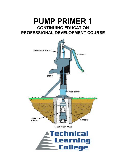
thoroughly documented. The first pumps<br />
used in Cornwall were called bucket pumps,<br />
which we recognize as lift pumps, with the<br />
pistons somewhat miscalled buckets. They<br />
pumped on the up-stroke, when a clack in<br />
the bottom of the pipe opened and allowed<br />
water to enter beneath the piston. At the<br />
same time, the piston lifted the column of<br />
water above it, which could be of any<br />
length. The piston could only "suck" water<br />
33 ft, or 28 ft more practically, of course, but<br />
this occurred at the bottom of the shaft, so<br />
this was only a limit on the piston stroke. On<br />
the down stroke, a clack in the bucket<br />
opened, allowing it to sink through the water to the bottom, where it would be ready to make<br />
another lift. More satisfactory were the plunger pumps, also placed at the bottom of the shaft. A<br />
plunger displaced volume in a chamber, forcing the water in it through a check valve up the<br />
shaft, when it descended. When it rose, water entered the pump chamber through a clack, as in<br />
the bucket pump.<br />
Only the top of the plunger had to be packed; it was not necessary that it fit the cylinder<br />
accurately. In this case, the engine at the surface lifted the heavy pump rods on the up-stroke.<br />
When the atmospheric engine piston returned, the heavy timber pump rods did the actual<br />
pumping, borne down by their weight. A special application for pumps is to produce a vacuum<br />
by exhausting a container, called the receiver.<br />
Hawksbee's Dual Cylinder <strong>Pump</strong><br />
Hawksbee's dual cylinder pump, designed in the 18th century, is the final form of the air pump<br />
invented by Guericke by 1654. A good pump could probably reach about 5-10 mmHg, the limit<br />
set by the valves. The cooperation of the cylinders made the pump much easier to work when<br />
the pressure was low. In the diagram, piston A is descending, helped by the partial vacuum<br />
remaining below it, while piston B is rising, filling with the low-pressure air from the receiver.<br />
Bell-jar Receiver<br />
The bell-jar receiver, invented by Huygens, is shown; previously, a cumbersome globe was the<br />
usual receiver. Tate's air pump is a 19th century pump that would be used for simple vacuum<br />
demonstrations and for utility purposes in the lab. It has no valves on the low-pressure side, just<br />
exhaust valves V, V', so it could probably reach about 1 mmHg. It is operated by pushing and<br />
pulling the handle H. At the present day, motor-driven rotary-seal pumps sealed by running in oil<br />
are used for the same purpose. At the right is Sprengel's pump, with the valves replaced by<br />
drops of mercury.<br />
<strong>Pump</strong> <strong>Primer</strong> I Course © 12/1/2012 (866) 557-1746 www.ABCTLC.com<br />
32
Small amounts of gas are trapped at the top of the fall tube as the mercury drops, and moves<br />
slowly down the fall tube as mercury is steadily added, coming out at the bottom carrying the air<br />
with it. The length of the fall tube must be greater than the barometric height, of course.<br />
Theoretically, a vacuum of about 1 μm can be obtained with a Sprengel pump, but it is very slow<br />
and can only evacuate small volumes. Later, Langmuir's mercury diffusion pump, which was<br />
much faster, replaced Sprengel pumps, and led to oil diffusion pumps that can reach very high<br />
vacua. The column of water or hydrostatic engine is the inverse of the force pump, used to turn<br />
a large head (pressure) of water into rotary motion. It looks like a steam engine, with valves<br />
operated by valve gear, but of course is not a heat engine and can be of high efficiency.<br />
However, it is not of as high efficiency as a turbine, and is much more complicated, but has the<br />
advantage that it can be operated at variable speeds, as for lifting. A few very impressive<br />
column of water engines were made in the 19th century, but they were never popular and<br />
remained rare. Richard Trevithick, famous for high pressure steam engines, also built<br />
hydrostatic engines in Cornwall. The photograph at the right shows a column-of-water engine<br />
built by Georg von Reichenbach, and placed in service in 1917. This engine was exhibited in the<br />
Deutsches Museum in München as late as 1977.<br />
It was used to pump brine for the Bavarian state salt industry. A search of the museum website<br />
did not reveal any evidence of it, but a good drawing of another brine pump with four cylinders<br />
and driven by a water wheel, also built by von Reichenbach, was found.<br />
Solehebemaschine<br />
This machine, a Solehebemaschine ("brine-lifting machine"), entered service in 1821. It had two<br />
pressure-operated poppet valves for each cylinder. These engines<br />
are brass to resist corrosion by the salt water. Water pressure<br />
engines must be designed taking into account the incompressibility<br />
of water, so both valves must not close at the same time, and abrupt<br />
changes of rate of flow must not be made. Air chambers can be used<br />
to eliminate shocks. Georg von Reichenbach (1771-1826) is much<br />
better known as an optical designer than as a mechanical engineer.<br />
He was associated with Joseph Fraunhofer, and they died within<br />
days of each other in 1826. He was of an aristocratic family, and was<br />
Salinenrat, or manager of the state salt works, in southeastern<br />
Bavaria, which was centered on the town of Reichenhall, now Bad<br />
Reichenhall, near Salzburg.<br />
The name derives from "rich in salt." This famous salt region had salt<br />
springs flowing nearly saturated brine, at 24% to 26% (saturated is<br />
27%) salt, that from ancient times had been evaporated over wood<br />
fires. A brine pipeline to Traunstein was constructed in 1617-1619, since wood fuel for<br />
evaporating the brine was exhausted in Reichenhall. The pipeline was further extended to<br />
Rosenheim, where there was turf as well as wood, in 1818-10. Von Reichenbach is said to<br />
have built this pipeline, for which he designed a water-wheel-driven, four-barrel pump.<br />
Maximilian I, King of Bavaria, commissioned von Reichenbach to bring brine from<br />
Berchtesgaden, elevation 530 m, to Reichenhall, elevation 470 m, over a summit 943 m high.<br />
<strong>Pump</strong> <strong>Primer</strong> I Course © 12/1/2012 (866) 557-1746 www.ABCTLC.com<br />
33
Forces on Submerged Surfaces<br />
Suppose we want to know the force exerted on a vertical surface of any shape with water on<br />
one side, assuming gravity to act, and the pressure on the surface of the water zero. We have<br />
already solved this problem by a geometrical<br />
argument, but now we apply calculus, which is<br />
easier but not as illuminating.<br />
The force on a small area dA a distance x below the<br />
surface of the water is dF = p dA = ρgx dA, and the<br />
moment of this force about a point on the surface is<br />
dM = px dA = ρgx2 dA.<br />
By integration, we can find the total force F, and the<br />
depth at which it acts, c = M / F. If the surface is not<br />
symmetrical, the position of the total force in the<br />
transverse direction can be obtained from the<br />
integral of dM' = ρgxy dA, the moment about some vertical line in the plane of the surface. If<br />
there happens to be a pressure on the free surface of the water, then the forces due to this<br />
pressure can be evaluated separately and added to this result. We must add a force equal to<br />
the area of the surface times the additional pressure, and a moment equal to the product of this<br />
force and the distance to the centroid of the surface.<br />
The simplest case is a rectangular gate of width w, and height h, whose top is a distance H<br />
below the surface of the water.<br />
In this case, the integrations are very easy, and F = ρgw [(h + H) 2 - h2]/2 = ρgH (H + 2h)/2 = ρg<br />
(h + H/2) Hw.<br />
The total force on the gate is equal to its area times the pressure at its centre. M = ρgw [(h + H)<br />
3 - h3]/3 = ρg (H2/3 + Hh + h2) Hw, so that c = (H2/3 + Hh + h2)/ (h + H/2).<br />
In the simple case of h = 0, c = 2H/3, or two-thirds of the way from the top to the bottom of the<br />
gate. If we take the atmospheric pressure to act not only on the surface of the water, but also<br />
the dry side of the gate, there is no change to this result. This is the reason atmospheric<br />
pressure often seems to have been neglected in solving sub h problems.<br />
Consider a curious rectangular tank, with one side vertical but the opposite side inclined inwards<br />
or outwards. The horizontal forces exerted by the water on the two sides must be equal and<br />
opposite, or the tank would scoot off. If the side is inclined outward, then there must be a<br />
downward vertical force equal to the weight of the water above it, and passing through the<br />
centroid of this water. If the side is inclined inward, there must be an upward vertical force equal<br />
to the weight of the 'missing' water above it. In both cases, the result is demanded by ordinary<br />
statics.<br />
<strong>Pump</strong> <strong>Primer</strong> I Course © 12/1/2012 (866) 557-1746 www.ABCTLC.com<br />
34
Hydrostatic Paradox<br />
What we have here has been called the 'hydrostatic paradox.' It was conceived by the<br />
celebrated Flemish engineer Simon Stevin (1548-1620) of Brugge, the first modern scientist to<br />
investigate the statics of fluids and solids. Consider three tanks with bottoms of equal sizes and<br />
equal heights, filled with water. The pressures at the bottoms are equal, so the vertical force on<br />
the bottom of each tank is the same. But suppose that one tank has vertical sides, one has<br />
sides inclined inward, and third sides inclined outwards. The tanks do not contain the same<br />
weight of water, yet the forces on their bottoms are equal! I am sure that you can spot the<br />
resolution of this paradox.<br />
Sometimes the forces are required on curved surfaces.<br />
The vertical and horizontal components can be found by<br />
considering the equilibrium of volumes with a plane<br />
surface equal to the projected area of the curved surface<br />
in that direction. The general result is usually a force plus<br />
a couple, since the horizontal and vertical forces are not<br />
necessarily in the same plane. Simple surfaces, such as<br />
cylinders, spheres and cones, may often be easy to<br />
solve. In general, however, it is necessary to sum the<br />
forces and moments numerically on each element of area, and only in simple cases can this be<br />
done analytically.<br />
If a volume of fluid is accelerated uniformly, the acceleration can be added to the acceleration of<br />
gravity. A free surface now becomes perpendicular to the total acceleration, and the pressure is<br />
proportional to the distance from this surface. The same can be done for a rotating fluid, where<br />
the centrifugal acceleration is the important quantity. The earth's atmosphere is an example.<br />
When air moves relative to the rotating system, the Coriolis force must also be taken into<br />
account. However, these are dynamic effects and are not strictly a part of hydrostatics.<br />
Buoyancy<br />
Archimedes, so the legend runs, was asked to determine if the goldsmith who made a golden<br />
crown for Hieron, Tyrant of Syracuse, had substituted cheaper metals for gold. The story is told<br />
by Vitruvius. A substitution could not be detected by simply weighing the crown, since it was<br />
craftily made to the same weight as the gold supplied for its construction. Archimedes realized<br />
that finding the density of the crown, that is, the weight per unit volume, would give the answer.<br />
The weight was known, of course, and Archimedes cunningly measured its volume by the<br />
amount of water that ran off when it was immersed in a vessel filled to the brim. By comparing<br />
the results for the crown, and for pure gold, it was found that the crown displaced more water<br />
than an equal weight of gold, and had, therefore, been adulterated. This story, typical of the<br />
charming way science was made more interesting in classical times, may or may not actually<br />
have taken place, but whether it did or not, Archimedes taught that a body immersed in a fluid<br />
lost apparent weight equal to the weight of the fluid displaced, called Archimedes' Principle.<br />
Specific gravity, the ratio of the density of a substance to the density of water, can be<br />
determined by weighing the body in air, and then in water. The specific gravity is the weight in<br />
air divided by the loss in weight when immersed. This avoids the difficult determination of the<br />
exact volume of the sample.<br />
<strong>Pump</strong> <strong>Primer</strong> I Course © 12/1/2012 (866) 557-1746 www.ABCTLC.com<br />
35
How Buoyancy Works<br />
To see how buoyancy works, consider a submerged brick, of height h, width w and length l. The<br />
difference in pressure on top and bottom of the brick is ρgh, so the difference in total force on<br />
top and bottom of the brick is simply (ρgh) (wl) =<br />
ρgV, where V is the volume of the brick.<br />
The forces on the sides have no vertical<br />
components, so they do not matter. The net<br />
upward force is the weight of a volume V of the<br />
fluid of density ρ. Anybody can be considered<br />
made up of brick shapes, as small as desired, so<br />
the result applies in general. This is just the<br />
integral calculus in action, or the application of<br />
Professor Thomson's analogy.<br />
Consider a man in a rowboat on a lake, with a<br />
large rock in the boat. He throws the rock into the<br />
water. What is the effect on the water level of the lake Suppose you make a drink of ice water<br />
with ice cubes floating in it. What happens to the water level in the glass when the ice has<br />
melted<br />
The force exerted by the water on the bottom of a boat acts through the centre of gravity B of<br />
the displaced volume, while the force exerted by gravity on the boat acts through its own centre<br />
of gravity A. This looks bad for the boat, since the boat's c.g. will naturally be higher than the<br />
c.g. of the displaced water, so the boat will tend to capsize. Well, a board floats, and can tell us<br />
why. Should the board start to rotate to one side, the displaced volume immediately moves to<br />
that side, and the buoyant force tends to correct the rotation. A floating body will be stable<br />
provided the line of action of the buoyant force passes through a point M above the c.g. of the<br />
body, called the metacenter, so that there is a restoring couple when the boat heels. A ship with<br />
an improperly designed hull will not float. It is not as easy to make boats as it might appear.<br />
Montgolfier Brothers' Hot Air Balloon<br />
Archimedes’ Principle can also be applied to balloons. The Montgolfier brothers' hot air balloon<br />
with a paper envelope ascended first in 1783 (the brothers got Pilâtre de Rozier and Chevalier<br />
d'Arlandes to go up in it). Such "fire balloons" were then replaced with hydrogen-filled balloons,<br />
and then with balloons filled with coal gas, which was easier to obtain and did not diffuse<br />
through the envelope quite as rapidly. Methane would be a good filler, with a density 0.55 that of<br />
air. Slack balloons, like most large ones, can be contrasted with taut balloons with an elastic<br />
envelope, such as weather balloons. Slack balloons will not be filled full on the ground, and will<br />
plump up at altitude. Balloons are naturally stable, since the center of buoyancy is above the<br />
center of gravity in all practical balloons. Submarines are yet another application of buoyancy,<br />
with their own characteristic problems. Small neoprene or natural rubber balloons have been<br />
used for meteorological observations, with hydrogen filling. A 10g ceiling balloon was about 17"<br />
in diameter when inflated to have a free lift of 40g. It ascended 480ft the first minute, 670ft in a<br />
minute and a half, and 360ft per minute afterwards, to find cloud ceilings by timing, up to 2500ft,<br />
when it subtended about 2' of arc, easily seen in binoculars.<br />
<strong>Pump</strong> <strong>Primer</strong> I Course © 12/1/2012 (866) 557-1746 www.ABCTLC.com<br />
36
Large sounding balloons were used to lift a radiosonde and a parachute for its recovery. An<br />
AN/AMT-2 radiosonde of the 1950's weighed 1500g, the paper parachute 100g, and the balloon<br />
350g. The balloon was inflated to give 800g free lift, so it would rise 700-800 ft/min to an altitude<br />
of about 50,000 ft (15 km) before it burst. This balloon was about 6 ft in diameter when inflated<br />
at the surface, 3 ft in diameter before inflation. The information was returned by radio telemetry,<br />
so the balloon did not have to be followed optically. Of intermediate size was the pilot balloon,<br />
which was followed with a theodolite to determine wind directions and speeds. At night, a pilot<br />
balloon could carry a light for ceiling determinations.<br />
Weather Balloons<br />
The greatest problem with using hydrogen for lift is that it diffuses rapidly through many<br />
substances. Weather balloons had to be launched promptly after filling, or the desired free lift<br />
would not be obtained. Helium is a little better in this respect, but it also diffuses rapidly. The lift<br />
obtained with helium is almost the same as with hydrogen (density 4 compared to 2, where air is<br />
28.97). However, helium is exceedingly rare, and only its unusual occurrence in natural gas<br />
from Kansas makes it available. Great care must be taken when filling balloons with hydrogen to<br />
avoid sparks and the accumulation of hydrogen in air, since hydrogen is exceedingly flammable<br />
and explosive over a wide range of concentrations. Helium has the great advantage that it is not<br />
inflammable.<br />
The hydrogen for filling weather balloons came from compressed gas in cylinders, from the<br />
reaction of granulated aluminum with sodium hydroxide and water, or from the reaction of<br />
calcium hydroxide with water. The chemical reactions are 2Al + 2NaOH + 2H2O → 2NaAlO2 +<br />
3H2, or CaH2 + 2H2O → Ca (OH) 2 + 2H2. In the first, silicon or zinc could be used instead of<br />
aluminum, and in the second, any similar metal hydride. Both are rather expensive sources of<br />
hydrogen, but very convenient when only small amounts are required. Most hydrogen is made<br />
from the catalytic decomposition of hydrocarbons, or the reaction of hot coke with steam.<br />
Electrolysis of water is an expensive source, since more energy is used than is recovered with<br />
the hydrogen. Any enthusiasm for a "hydrogen economy" should be tempered by the fact that<br />
there are no hydrogen wells, and all the hydrogen must be made with an input of energy usually<br />
greater than that available from the hydrogen, and often with the appearance of carbon.<br />
Although about 60,000 Btu/lb is available from hydrogen, compared to 20,000 Btu/lb from<br />
gasoline, hydrogen compressed to 1000 psi requires 140 times as much volume for the same<br />
weight as gasoline. For the energy content of a 13-gallon gasoline tank, a 600-gallon hydrogen<br />
tank would be required. The critical temperature of hydrogen is 32K, so liquid storage is out of<br />
the question for general use.<br />
Measurement of Specific Gravity<br />
The specific gravity of a material is the ratio of the mass (or weight) of a certain sample of it to<br />
the mass (or weight) of an equal volume of water, the conventional reference material. In the<br />
metric system, the density of water is 1 g/cc, which makes the specific gravity numerically equal<br />
to the density. Strictly speaking, density has the dimensions g/cc, while specific gravity is a<br />
dimensionless ratio. However, in casual speech the two are often confounded. In English units,<br />
however, density, perhaps in lb/cu.ft or pcf, is numerically different from the specific gravity,<br />
since the weight of water is 62.5 lb/cu.ft.<br />
<strong>Pump</strong> <strong>Primer</strong> I Course © 12/1/2012 (866) 557-1746 www.ABCTLC.com<br />
37
Variations<br />
Things are complicated by the variation of the density of water with temperature, and also by the<br />
confusion that gave us the distinction between cc and ml. The milliliter is the volume of 1.0 g of<br />
water at 4°C, by definition. The actual volume of 1.0 g of water at 4°C is 0.999973 cm3 by<br />
measurement. Since most densities are not known, or needed, to more than three significant<br />
figures, it is clear that this difference is of no practical importance, and the ml can be taken<br />
equal to the cc. The density of water at 0°C is 0.99987 g/ml, at 20° 0.99823, and at 100°C<br />
0.95838. The temperature dependence of the density may have to be taken into consideration<br />
in accurate work. Mercury, while we are at it, has a density 13.5955 at 0°C, and 13.5461 at<br />
20°C.<br />
The basic idea in finding specific gravity is to weigh a sample in air, and then immersed in<br />
water. Then the specific gravity is W/ (W - W'), if W is the weight in air, and W' the weight<br />
immersed. The denominator is just the buoyant force, the weight of a volume of water equal to<br />
the volume of the sample. This can be carried out with an ordinary balance, but special<br />
balances, such as the Jolly balance, have been created specifically for this application. Adding<br />
an extra weight to the sample allows measurement of specific gravities less than 1.<br />
Pycnometer<br />
A pycnometer is a flask with a close-fitting ground glass stopper with a fine hole through it, so a<br />
given volume can be accurately obtained. The name comes from the Greek word meaning<br />
"density." If the flask is weighed empty, full of water, and full of a liquid whose specific gravity is<br />
desired, the specific gravity of the liquid can easily be calculated. A sample in the form of a<br />
powder, to which the usual method of weighing cannot be used, can be put into the pycnometer.<br />
The weight of the powder and the weight of the displaced water can be determined, and from<br />
them the specific gravity of the powder.<br />
The specific gravity of a liquid can be found with a collection of small weighted, hollow spheres<br />
that will just float in certain specific gravities. The closest spheres that will just float and just sink<br />
put limits on the specific gravity of the liquid. This method was once used in Scotland to<br />
determine the amount of alcohol in distilled liquors. Since the density of a liquid decreases as<br />
the temperature increases, the spheres that float are an indication of the temperature of the<br />
liquid. Galileo's thermometer worked this way.<br />
Hydrometer<br />
A better instrument is the hydrometer, which consists of a weighted float and a calibrated stem<br />
that protrudes from the liquid when the float is entirely immersed. A higher specific gravity will<br />
result in a greater length of the stem above the surface, while a lower specific gravity will cause<br />
the hydrometer to float lower.<br />
The small cross-sectional area of the stem makes the instrument very sensitive. Of course, it<br />
must be calibrated against standards. In most cases, the graduations ("degrees") are arbitrary<br />
and reference is made to a table to determine the specific gravities. Hydrometers are used to<br />
determine the specific gravity of lead-acid battery electrolyte, and the concentration of antifreeze<br />
compounds in engine coolants, as well as the alcohol content of whiskey.<br />
<strong>Pump</strong> <strong>Primer</strong> I Course © 12/1/2012 (866) 557-1746 www.ABCTLC.com<br />
38
Pascal’s Law<br />
The foundation of modern hydraulics was established when Pascal discovered that pressure in<br />
a fluid acts equally in all directions. This pressure acts at right angles to the containing surfaces.<br />
If some type of pressure gauge, with an exposed face, is placed beneath the surface of a liquid<br />
at a specific depth and pointed in different directions, the pressure will read the same. Thus, we<br />
can say that pressure in a liquid is independent of direction.<br />
Pressure due to the weight of a liquid, at any level, depends on the depth of the fluid from the<br />
surface. If the exposed face of the pressure gauges are moved closer to the surface of the<br />
liquid, the indicated pressure will be less. When the depth is doubled, the indicated pressure is<br />
doubled. Thus the pressure in a liquid is directly proportional to the depth. Consider a container<br />
with vertical sides that is 1 foot long and 1 foot wide. Let it be filled with water 1 foot deep,<br />
providing 1 cubic foot of water. 1 cubic foot of water weighs 62.4 pounds. Using this information<br />
and equation, P = F/A, we can calculate the pressure on the bottom of the container.<br />
Since there are 144 square inches in 1 square foot, this can be stated as follows: the weight of a<br />
column of water 1 foot high, having a cross-sectional area of 1 square inch, is 0.433 pound. If<br />
the depth of the column is tripled, the weight of the column will be 3 x 0.433, or 1.299 pounds,<br />
and the pressure at the bottom will be 1.299 lb/in 2 (psi), since pressure equals the force divided<br />
by the area.<br />
Thus, the pressure at any depth in a liquid is equal to the weight of the column of liquid at that<br />
depth divided by the cross-sectional area of the column at that depth. The volume of a liquid<br />
that produces the pressure is referred to as the fluid head of the liquid. The pressure of a liquid<br />
due to its fluid head is also dependent on the density of the liquid.<br />
Gravity<br />
Gravity is one of the four forces of nature. The strength of the gravitational force between two<br />
objects depends on their masses. The more massive the objects are, the stronger the<br />
gravitational attraction. When you pour water out of a container, the earth's gravity pulls the<br />
water towards the ground. The same thing happens when you put two buckets of water, with a<br />
tube between them, at two different heights. You must work to start the flow of water from one<br />
bucket to the other, but then gravity takes over and the process will continue on its own.<br />
Gravity, applied forces, and atmospheric pressure are static factors that apply equally to fluids<br />
at rest or in motion, while inertia and friction are dynamic factors that apply only to fluids in<br />
motion. The mathematical sum of gravity, applied force, and atmospheric pressure is the static<br />
pressure obtained at any one point in a fluid at any given time.<br />
Static Pressure<br />
Static pressure exists in addition to any dynamic factors that may also be present at the same<br />
time. Pascal’s law states that a pressure set up in a fluid acts equally in all directions and at<br />
right angles to the containing surfaces. This covers the situation only for fluids at rest or<br />
practically at rest. It is true only for the factors making up static head.<br />
<strong>Pump</strong> <strong>Primer</strong> I Course © 12/1/2012 (866) 557-1746 www.ABCTLC.com<br />
39
Obviously, when velocity becomes a factor it must have a direction, and as previously<br />
explained, the force related to the velocity must also have a direction, so that Pascal’s law alone<br />
does not apply to the dynamic factors of fluid power.<br />
The dynamic factors of inertia and friction are related to the static factors. Velocity head and<br />
friction head are obtained at the expense of static head. However, a portion of the velocity head<br />
can always be reconverted to static head. Force, which can be produced by pressure or head<br />
when dealing with fluids, is necessary to start a body moving if it is at rest, and is present in<br />
some form when the motion of the body is arrested; therefore, whenever a fluid is given velocity,<br />
some part of its original static head is used to impart this velocity, which then exists as velocity<br />
head.<br />
Volume and Velocity of Flow<br />
The volume of a liquid passing a point in a given time is known as its volume of flow or flow rate.<br />
The volume of flow is usually expressed in gallons per minute (gpm) and is associated with<br />
relative pressures of the liquid, such as 5 gpm at 40 psi. The velocity of flow or velocity of the<br />
fluid is defined as the average speed at which the fluid moves past a given point. It is usually<br />
expressed in feet per second (fps) or feet per minute (fpm). Velocity of flow is an important<br />
consideration in sizing the hydraulic lines. Volume and velocity of flow are often considered<br />
together. With other conditions unaltered—that is, with volume of input unchanged—the velocity<br />
of flow increases as the cross section or size of the pipe decreases, and the velocity of flow<br />
decreases as the cross section increases. For example, the velocity of flow is slow at wide parts<br />
of a stream and rapid at narrow parts, yet the volume of water passing each part of the stream<br />
is the same.<br />
Bernoulli's Principle<br />
Bernoulli's principle thus says that a rise (fall) in pressure in a flowing fluid must always be<br />
accompanied by a decrease (increase) in the speed, and conversely, if an increase (decrease)<br />
in, the speed of the fluid results in a decrease (increase) in the pressure. This is at the heart of a<br />
number of everyday phenomena. As a very trivial<br />
example, Bernoulli’s principle is responsible for<br />
the fact that a shower curtain gets “sucked<br />
inwards'' when the water is first turned on. What<br />
happens is that the increased water/air velocity<br />
inside the curtain (relative to the still air on the<br />
other side) causes a pressure drop.<br />
The pressure difference between the outside and<br />
inside causes a net force on the shower curtain<br />
which sucks it inward. A more useful example is<br />
provided by the functioning of a perfume bottle:<br />
squeezing the bulb over the fluid creates a low<br />
pressure area due to the higher speed of the air,<br />
which subsequently draws the fluid up. This is<br />
illustrated in the following figure.<br />
Action of a spray atomizer<br />
<strong>Pump</strong> <strong>Primer</strong> I Course © 12/1/2012 (866) 557-1746 www.ABCTLC.com<br />
40
Bernoulli’s principle also tells us why windows tend to explode, rather than implode in<br />
hurricanes: the very high speed of the air just outside the window causes the pressure just<br />
outside to be much less than the pressure inside, where the air is still. The difference in force<br />
pushes the windows outward, and hence they explode. If you know that a hurricane is coming it<br />
is therefore better to open as many windows as possible, to equalize the pressure inside and<br />
out.<br />
Another example of Bernoulli's principle at work is in the lift of aircraft wings and the motion of<br />
“curve balls'' in baseball. In both cases the design is such as to create a speed differential of<br />
the flowing air past the object on the top and the bottom - for aircraft wings this comes from the<br />
movement of the flaps, and for the baseball it is the presence of ridges. Such a speed<br />
differential leads to a pressure difference between the top and bottom of the object, resulting in<br />
a net force being exerted, either upwards or downwards.<br />
<strong>Pump</strong> <strong>Primer</strong> I Course © 12/1/2012 (866) 557-1746 www.ABCTLC.com<br />
41
42<br />
<strong>Pump</strong> <strong>Primer</strong> I Course © 12/1/2012 (866) 557-1746 www.ABCTLC.com
Understanding the Venturi<br />
It is not easy to understand the reason low pressure occurs in the small diameter area of the<br />
venturi. This explanation may seem to help the principle.<br />
It is clear that all the flow must pass from the larger section to the smaller section. Or in other<br />
words, the flow rate will remain the same in the large and small portions of the tube. The flow<br />
rate is the same rate, but the velocity changes. The velocity is greater in the small portion of the<br />
tube. There is a relationship between the pressure energy and the velocity energy; if velocity<br />
increases the pressure energy must decrease.<br />
This is known as the principle of conservation of energy at work which is also Bernoulli's law.<br />
This is similar to the soapbox derby car in the illustration at the top of a hill. At the top or point,<br />
the elevation of the soapbox derby car is high and the velocity low. At the bottom the elevation<br />
is low and the velocity is high, elevation (potential) energy has been converted to velocity<br />
(kinetic) energy. Pressure and velocity energies behave in the same way. In the large part of the<br />
pipe the pressure is high and velocity is low, in the small part, pressure is low and velocity high.<br />
<strong>Pump</strong> <strong>Primer</strong> I Course © 12/1/2012 (866) 557-1746 www.ABCTLC.com<br />
43
44<br />
<strong>Pump</strong> <strong>Primer</strong> I Course © 12/1/2012 (866) 557-1746 www.ABCTLC.com
<strong>Pump</strong> Introduction<br />
<strong>Pump</strong>s are used to move or raise fluids. They are not only very useful, but are excellent<br />
examples of hydrostatics. <strong>Pump</strong>s are of two general types, hydrostatic or positive displacement<br />
pumps, and pumps depending on dynamic forces, such as centrifugal pumps. Here we will only<br />
consider positive displacement pumps, which can be understood purely by hydrostatic<br />
considerations. They have a piston (or equivalent) moving in a closely-fitting cylinder and forces<br />
are exerted on the fluid by motion of the piston.<br />
We have already seen an important example of this in the hydraulic lever or hydraulic press,<br />
which we have called quasi-static. The simplest pump is the syringe, filled by withdrawing the<br />
piston and emptied by pressing it back in, as its port is immersed in the fluid or removed from it.<br />
<strong>Pump</strong> Safety Regulations<br />
It is a necessity that your safety department establishes a safety program based upon a<br />
thorough analysis of industrial hazards. Before installing and operating or performing<br />
maintenance on the pump and associated components described in this manual, it is important<br />
to ensure that it covers the hazards arising from high speed rotating machinery. It is also<br />
important that due consideration be given to those hazards which arise from the presence of<br />
electrical power, hot oil, high pressure and temperature liquids, toxic liquids and gases, and<br />
flammable liquids and gases.<br />
<strong>Pump</strong> <strong>Primer</strong> I Course © 12/1/2012 (866) 557-1746 www.ABCTLC.com<br />
45
Proper installation and care of protective guards, shut-down devices and over pressure<br />
protection equipment must also be considered an essential part of any safety program.<br />
Also essential are special precautionary measures to prevent the possibility of applying power to<br />
the equipment at any time when maintenance work is in progress. The prevention of rotation<br />
due to reverse flow should not be overlooked. In general, all personnel should be guided by all<br />
the basic rules of safety associated with the equipment and the process. It should be<br />
understood that the information contained in this manual does not relieve operating and<br />
maintenance personnel of the responsibility of exercising good judgment in operation and care<br />
of the pump and its components.<br />
In the following safety procedures you will encounter the words DANGER, WARNING,<br />
CAUTION, and NOTICE. These are intended to emphasize certain areas in the interest of<br />
personal safety and satisfactory pump operation and maintenance. The definitions of these<br />
words are as follows:<br />
“DANGER” Danger is used to indicate the presence<br />
of a hazard which will cause severe<br />
personal injury, death, or substantial property<br />
damage if the warning is ignored.<br />
“WARNING” Warning is used to indicate the<br />
presence of a hazard which can cause severe<br />
personal injury, death, or substantial property<br />
damage if the warning is ignored.<br />
“CAUTION” Caution is used to indicate the presence<br />
of a hazard which will or can cause<br />
minor personal injury, death, or substantial property<br />
damage if the warning is ignored.<br />
<strong>Pump</strong> Applications<br />
<strong>Pump</strong>s are used throughout society for a variety of purposes. Early applications include the use<br />
of the windmill or watermill to pump water. Today, the pump is used for irrigation, water supply,<br />
gasoline supply, air conditioning systems, refrigeration (usually called a compressor), chemical<br />
movement, sewage movement, flood control, marine services, etc. Because of the wide variety<br />
of applications, pumps have a plethora of shapes and sizes: from very large to very small, from<br />
handling gas to handling liquid, from high pressure to low pressure, and from high volume to low<br />
volume.<br />
<strong>Pump</strong> <strong>Primer</strong> I Course © 12/1/2012 (866) 557-1746 www.ABCTLC.com<br />
46
Complicated <strong>Pump</strong>s<br />
More complicated pumps have valves allowing them to work repetitively. These are usually<br />
check valves that open to allow passage in one direction, and close automatically to prevent<br />
reverse flow. There are many kinds of valves, and they are usually the most trouble-prone and<br />
complicated part of a pump. The force pump has two check valves in the cylinder, one for<br />
supply and the other for delivery. The supply valve opens when the cylinder volume increases,<br />
the delivery valve when the cylinder volume decreases. The lift pump has a supply valve and a<br />
valve in the piston that allows the liquid to pass around it when the volume of the cylinder is<br />
reduced. The delivery in this case is from the upper part of the cylinder, which the piston does<br />
not enter.<br />
Diaphragm pumps are force pumps in which the oscillating diaphragm takes the place of the<br />
piston. The diaphragm may be moved mechanically, or by the pressure of the fluid on one side<br />
of the diaphragm.<br />
Some positive displacement pumps are shown below. The force and lift pumps are typically<br />
used for water. The force pump has two valves in the cylinder, while the lift pump has one valve<br />
in the cylinder and one in the piston. The maximum lift, or "suction," is determined by the<br />
atmospheric pressure, and either cylinder must be within this height of the free surface. The<br />
force pump, however, can give an arbitrarily large pressure to the discharged fluid, as in the<br />
case of a diesel engine injector. A nozzle can be used to convert the pressure to velocity, to<br />
produce a jet, as for firefighting. Fire fighting force pumps usually have two cylinders feeding<br />
one receiver alternately. The air space in the receiver helps to make the water pressure uniform.<br />
<strong>Pump</strong> <strong>Primer</strong> I Course © 12/1/2012 (866) 557-1746 www.ABCTLC.com<br />
47
The three pumps above are typically used for air, but would be equally applicable to liquids. The<br />
Roots blower has no valves, their place taken by the sliding contact between the rotors and the<br />
housing. The Roots blower can either exhaust a receiver or provide air under moderate<br />
pressure, in large volumes. The Bellows is a very old device, requiring no accurate machining.<br />
The single valve is in one or both sides of the expandable chamber. Another valve can be<br />
placed at the nozzle if required. The valve can be a piece of soft leather held close to holes in<br />
the chamber. The Bicycle pump uses the valve on the valve stem of the tire or inner tube to hold<br />
pressure in the tire. The piston, which is attached to the discharge tube, has a flexible seal that<br />
seals when the cylinder is moved to compress the air, but allows air to pass when the<br />
movement is reversed.<br />
Diaphragm and vane pumps are not shown, but they act the same way by varying the volume of<br />
a chamber, and directing the flow with check valves.<br />
Fluid Properties<br />
The properties of the fluids being pumped can significantly affect the choice of pump. Key<br />
considerations include:<br />
• Acidity/alkalinity (pH) and chemical composition. Corrosive and acidic fluids can degrade<br />
pumps, and should be considered when selecting pump materials.<br />
<strong>Pump</strong> <strong>Primer</strong> I Course © 12/1/2012 (866) 557-1746 www.ABCTLC.com<br />
48
• Operating temperature. <strong>Pump</strong> materials and expansion, mechanical seal components, and<br />
packing materials need to be considered with pumped fluids that are hotter than 200°F.<br />
• Solids concentrations/particle sizes. When pumping abrasive liquids such as industrial<br />
slurries, selecting a pump that will not clog or fail prematurely depends on particle size,<br />
hardness, and the volumetric percentage of solids.<br />
• Specific gravity. The fluid specific gravity is the ratio of the fluid density to that of water under<br />
specified conditions. Specific gravity affects the energy required to lift and move the fluid, and<br />
must be considered when determining pump power requirements.<br />
• Vapor pressure. A fluid’s vapor pressure is the force per unit area that a fluid exerts in an<br />
effort to change phase from a liquid to a vapor, and depends on the fluid’s chemical and<br />
physical properties. Proper consideration of the fluid’s vapor pressure will help to minimize the<br />
risk of cavitation.<br />
• Viscosity. The viscosity of a fluid is a measure of its resistance to motion. Since kinematic<br />
viscosity normally varies directly with temperature, the pumping system designer must know the<br />
viscosity of the fluid at the lowest anticipated pumping temperature. High viscosity fluids result in<br />
reduced centrifugal pump performance and increased power requirements. It is particularly<br />
important to consider pump suction-side line losses when pumping viscous fluids.<br />
Environmental Considerations<br />
Important environmental considerations include ambient temperature and humidity, elevation<br />
above sea level, and whether the pump is to be installed indoors or outdoors.<br />
Software Tools<br />
Most pump manufacturers have developed software or Web-based tools to assist in the pump<br />
selection process. <strong>Pump</strong> purchasers enter their fluid properties and system requirements to<br />
obtain a listing of suitable pumps. Software tools that allow you to evaluate and compare<br />
operating costs are available from private vendors.<br />
<strong>Pump</strong>s as Public Water Supplies<br />
One sort of pump once common worldwide was a hand-powered water pump, or 'pitcher pump'.<br />
It would be installed over a community water well that was used by people in the days before<br />
piped water supplies. Because water from pitcher pumps is drawn directly from the soil, it is<br />
more prone to contamination. If such water is not filtered and purified, consumption of it might<br />
lead to gastrointestinal or other water-borne diseases. A notorious case is the 1854 Broad<br />
Street cholera outbreak. At the time it was not known how cholera was transmitted, but<br />
physician John Snow suspected contaminated water and had the handle of the public pump he<br />
suspected removed; the outbreak then subsided.<br />
Modern hand-operated community pumps are considered the most sustainable low-cost option<br />
for safe water supply in resource-poor settings, often in rural areas in developing countries. A<br />
hand pump opens access to deeper groundwater that is often not polluted and also improves<br />
the safety of a well by protecting the water source from contaminated buckets.<br />
<strong>Pump</strong>s such as the Afridev pump are designed to be cheap to build and install, and easy to<br />
maintain with simple parts. However, scarcity of spare parts for these types of pumps in some<br />
regions of Africa has diminished their utility for these areas.<br />
<strong>Pump</strong> <strong>Primer</strong> I Course © 12/1/2012 (866) 557-1746 www.ABCTLC.com<br />
49
Types of <strong>Pump</strong>s<br />
The family of pumps comprises a large number of types based on application and capabilities.<br />
The two major groups of pumps are dynamic and positive displacement.<br />
Dynamic <strong>Pump</strong>s (Centrifugal <strong>Pump</strong>)<br />
Centrifugal pumps are classified into three general categories:<br />
Radial flow—a centrifugal pump in which the pressure is developed wholly by centrifugal force.<br />
Mixed flow—a centrifugal pump in which the pressure is developed partly by centrifugal force<br />
and partly by the lift of the vanes of the impeller on the liquid.<br />
Axial flow—a centrifugal pump in which the pressure is developed by the propelling or lifting<br />
action of the vanes of the impeller on the liquid.<br />
A centrifugal pump has two main components:<br />
I. A rotating component comprised of an impeller and a shaft<br />
II. A stationary component comprised of a casing, casing cover, and bearings.<br />
<strong>Pump</strong> <strong>Primer</strong> I Course © 12/1/2012 (866) 557-1746 www.ABCTLC.com<br />
50
General <strong>Pump</strong>ing Fundamentals<br />
Here are the important points to consider about suction piping when the liquid being pumped is<br />
below the level of the pump:<br />
<br />
<br />
<br />
<br />
<br />
First, suction lift is when the level of water to be pumped is below the centerline of the<br />
pump. Sometimes suction lift is also referred to as ‘negative suction head’.<br />
The ability of the pump to lift water is the result of a partial vacuum created at the center<br />
of the pump.<br />
This works similar to sucking soda from a straw. As you gently suck on a straw, you are<br />
creating a vacuum or a pressure differential. Less pressure is exerted on the liquid inside<br />
the straw, so that the greater pressure is exerted on the liquid around the outside of the<br />
straw, causing the liquid in the straw to move up. By sucking on the straw, this allows<br />
atmospheric pressure to move the liquid.<br />
Look at the diagram illustrated as “1”. The foot valve is located at the end of the suction<br />
pipe of a pump. It opens to allow water to enter the suction side, but closes to prevent<br />
water from passing back out of the bottom end.<br />
The suction side of pipe should be one diameter larger than the pump inlet. The required<br />
eccentric reducer should be turned so that the top is flat and the bottom tapered.<br />
Notice in illustration “2” that the liquid is above the level of the pump. Sometimes this is referred<br />
to as ‘flooded suction’ or ‘suction head’ situations.<br />
Points to Note are:<br />
If an elbow and bell are used, they should be at least one pipe diameter from the tank bottom<br />
and side. This type of suction piping must have a gate valve which can be used to prevent the<br />
reverse flow when the pump has to be removed. In the illustrations you can see in both cases<br />
the discharge head is from the centerline of the pump to the level of the discharge water. The<br />
total head is the difference between the two liquid levels.<br />
<strong>Pump</strong> <strong>Primer</strong> I Course © 12/1/2012 (866) 557-1746 www.ABCTLC.com<br />
51
<strong>Pump</strong> Types come in Two Main Categories<br />
Centrifugal <strong>Pump</strong>s and Positive Displacement <strong>Pump</strong>s as classified according to the method of<br />
how the energy is imparted to the fluid – Kinetic Energy or Positive Displacement and again<br />
each of these categories having many pump types.<br />
Centrifugal <strong>Pump</strong><br />
Types the Kinetic Energy type which imparts velocity energy to the pumped medium which is<br />
converted to pressure energy when discharging the pump casing and can be grouped according<br />
to several criteria, further to that a specific pump can belong to different groups.<br />
These groups can be based upon:<br />
The impeller suction<br />
The number of impellers<br />
The type of volute<br />
International industry standards<br />
Shaft orientation<br />
Split case orientation<br />
Driver pump types<br />
Positive Displacement <strong>Pump</strong><br />
Types impart energy by mechanical displacement, these are of a lower flow range and are<br />
pulsating. PD pumps divided into two classes – reciprocating and rotary. Typical ‘PD’ pump<br />
types are:<br />
Rotary <strong>Pump</strong> Types:<br />
Rotary Gear <strong>Pump</strong>s<br />
Peripheral <strong>Pump</strong>s<br />
Screw <strong>Pump</strong>s<br />
Gear <strong>Pump</strong>s<br />
Rotary Lobe <strong>Pump</strong>s<br />
Reciprocating <strong>Pump</strong> Types<br />
Plunger <strong>Pump</strong>s<br />
Diaphragm <strong>Pump</strong>s<br />
Plunger <strong>Pump</strong>s<br />
Plunger pumps have a cylinder with a<br />
reciprocating plunger. The suction and<br />
discharge valves are mounted in the<br />
head of cylinder. The suction stroke pulls<br />
the plunger back, suction valve opens<br />
and fluid is sucked into the cylinder. The<br />
discharge stroke pushes the plunger forward closing suction valve and pushing fluid out of the<br />
discharge valve.<br />
Diaphragm <strong>Pump</strong>s<br />
Diaphragm pump types simply put use the plunger to pressurize either air or hydraulic fluid on<br />
one side which flexes the diaphragm which increases and decreases the volumetric area in the<br />
pumping chamber; non-return check valves ensure no back flow of the fluid.<br />
<strong>Pump</strong> <strong>Primer</strong> I Course © 12/1/2012 (866) 557-1746 www.ABCTLC.com<br />
52
Positive Displacement <strong>Pump</strong>s<br />
A Positive Displacement <strong>Pump</strong> has an expanding cavity on the suction side of the pump and a<br />
decreasing cavity on the discharge side. Liquid is allowed to flow into the pump as the cavity on<br />
the suction side expands and the liquid is forced out of the discharge as the cavity collapses.<br />
This principle applies to all types of Positive Displacement <strong>Pump</strong>s whether the pump is a rotary<br />
lobe, gear within a gear, piston, diaphragm, screw, progressing cavity, etc.<br />
A Positive Displacement <strong>Pump</strong>, unlike a Centrifugal <strong>Pump</strong>, will produce the same flow at a<br />
given RPM no matter what the discharge pressure is. A Positive Displacement <strong>Pump</strong> cannot be<br />
operated against a closed valve on the discharge side of the pump, i.e. it does not have a shutoff<br />
head like a Centrifugal <strong>Pump</strong> does. If a Positive Displacement <strong>Pump</strong> is allowed to operate<br />
against a closed discharge valve it will continue to produce flow which will increase the pressure<br />
in the discharge line until either the line bursts or the pump is severely damaged or both.<br />
Types of Positive Displacement <strong>Pump</strong>s<br />
Single Rotor Multiple Rotor<br />
Vane<br />
Piston<br />
Gear<br />
Lobe<br />
Flexible Member Circumferential Piston<br />
Single Screw<br />
Multiple Screw<br />
There are many types of positive<br />
displacement pumps. We will look at:<br />
Plunger pumps<br />
Diaphragm pumps<br />
Progressing cavity pumps, and<br />
Screw pumps<br />
Single Rotator<br />
Component<br />
Vane<br />
Piston<br />
Flexible Member<br />
Description<br />
The vane(s) may be blades, buckets, rollers, or slippers that cooperate with<br />
a dam to draw fluid into and out of the pump chamber.<br />
Fluid is drawn in and out of the pump chamber by a piston(s) reciprocating<br />
within a cylinder(s) and operating port valves.<br />
<strong>Pump</strong>ing and sealing depends on the elasticity of a flexible member(s) that<br />
may be a tube, vane, or a liner.<br />
<strong>Pump</strong> <strong>Primer</strong> I Course © 12/1/2012 (866) 557-1746 www.ABCTLC.com<br />
53
Single Screw<br />
Multiple Rotator<br />
Component<br />
Gear<br />
Lobe<br />
Circumferential piston<br />
Multiple Screw<br />
Fluid is carried between rotor screw threads as they mesh with internal<br />
threads on the stator.<br />
Description<br />
Fluid is carried between gear teeth and is expelled by the meshing of the<br />
gears that cooperate to provide continuous sealing between the pump inlet<br />
and outlet.<br />
Fluid is carried between rotor lobes that cooperate to provide continuous<br />
sealing between the pump inlet and outlet.<br />
Fluid is carried in spaces between piston surfaces not requiring contacts<br />
between rotor surfaces.<br />
Fluid is carried between rotor screw threads as they mesh.<br />
In the same way, the progressing cavity and the screw are two other types of mechanical action<br />
that can be used to provide movement of the liquid through the pump.<br />
Plunger <strong>Pump</strong><br />
The plunger pump is a positive displacement pump that uses a plunger or piston to force liquid<br />
from the suction side to the discharge side of the pump. It is used for heavy sludge. The<br />
movement of the plunger or piston inside the pump creates pressure inside the pump, so you<br />
have to be careful that this kind of pump is never operated against any closed discharge valve.<br />
All discharge valves must be open before the pump is started, to prevent any fast build-up of<br />
pressure that could damage the pump.<br />
Diaphragm <strong>Pump</strong>s<br />
In this type of pump, a diaphragm provides the mechanical action used to force liquid from the<br />
suction to the discharge side of the pump. The advantage the diaphragm has over the plunger is<br />
that the diaphragm pump does not come in contact with moving metal. This can be important<br />
when pumping abrasive or corrosive materials.<br />
There are three main types of diaphragm pumps available:<br />
1. Diaphragm sludge pump<br />
2. Chemical metering or proportional pump<br />
3. Air-powered double-diaphragm pump<br />
<strong>Pump</strong> <strong>Primer</strong> I Course © 12/1/2012 (866) 557-1746 www.ABCTLC.com<br />
54
<strong>Pump</strong> Specifications<br />
<strong>Pump</strong>s are commonly rated by horsepower, flow rate, outlet pressure in meters (or feet) of<br />
head, inlet suction in suction feet (or meters) of head. The head can be simplified as the number<br />
of feet or meters the pump can raise or lower a column of water at atmospheric pressure. From<br />
an initial design point of view, engineers often use a quantity termed the specific speed to<br />
identify the most suitable pump type for a particular combination of flow rate and head.<br />
<strong>Pump</strong> Construction Material<br />
The pump material can be Stainless steel (SS 316 or SS 304), cast iron etc. It depends on the<br />
application of the pump. In the water industry and for pharma applications SS 316 is normally<br />
used, as stainless steel gives better results at high temperatures.<br />
<strong>Pump</strong>ing Power<br />
The power imparted into a fluid will increase the energy of the fluid per unit volume. Thus the<br />
power relationship is between the conversion of the mechanical energy of the pump mechanism<br />
and the fluid elements within the pump. In general, this is governed by a series of simultaneous<br />
differential equations, known as the Navier-Stokes equations. However a more simple equation<br />
relating only the different energies in the fluid, known as Bernoulli's equation can be used.<br />
Hence the power, P, required by the pump:<br />
where ∆P is the change in total pressure between the inlet and outlet (in Pa), and Q, the fluid<br />
flowrate is given in m^3/s. The total pressure may have gravitational, static pressure and kinetic<br />
energy components; i.e. energy is distributed between change in the fluid's gravitational<br />
potential energy (going up or down hill), change in velocity, or change in static pressure. η is the<br />
pump efficiency, and may be given by the manufacturer's information, such as in the form of a<br />
pump curve, and is typically derived from either fluid dynamics simulation (i.e. solutions to the<br />
Navier-stokes for the particular pump geometry), or by testing. The efficiency of the pump will<br />
depend upon the pump's configuration and operating conditions (such as rotational speed, fluid<br />
density and viscosity etc.)<br />
For a typical "pumping" configuration, the work is imparted<br />
<strong>Pump</strong> <strong>Primer</strong> I Course © 12/1/2012 (866) 557-1746 www.ABCTLC.com<br />
55
Suction Lift Chart<br />
The vertical distance that a pump may be placed above the water level (and be able to draw<br />
water) is determined by pump design and limits dictated by altitude. The chart below shows the<br />
absolute limits. The closer the pump is to the water level, the easier and quicker it will be to<br />
prime.<br />
Suction Lift at Various Elevations<br />
Altitude: Suction Lift In Feet<br />
Sea Level 25.0<br />
2,000 ft. 22.0<br />
4,000 ft. 19.5<br />
6,000 ft. 17.3<br />
8,000 ft. 15.5<br />
10,000 ft. 14.3<br />
Centrifugal pumps are particularly vulnerable especially when pumping heated solution near the<br />
vapor pressure, whereas positive displacement pumps are less affected by cavitation, as they<br />
are better able to pump two-phase flow (the mixture of gas and liquid), however, the resultant<br />
flow rate of the pump will be diminished because of the gas volumetrically displacing a<br />
disproportion of liquid. Careful design is required to pump high temperature liquids with a<br />
centrifugal pump when the liquid is near its boiling point.<br />
The violent collapse of the cavitation bubble creates a shock wave that can literally carve<br />
material from internal pump components (usually the leading edge of the impeller) and creates<br />
noise often described as "pumping gravel".<br />
Additionally, the inevitable increase in vibration can cause other mechanical faults in the pump<br />
and associated equipment.<br />
For a typical "pumping" configuration, the work is imparted on the fluid, and is thus positive. For<br />
the fluid imparting the work on the pump (i.e. a turbine), the work is negative power required to<br />
drive the pump is determined by dividing the output power by the pump efficiency. Furthermore,<br />
this definition encompasses pumps with no moving parts, such as a siphon.<br />
When asked how a pump operates, most reply that it “sucks.” While not a false statement, it’s<br />
easy to see why so many pump operators still struggle with pump problems. Fluid flows from<br />
areas of high pressure to areas of low pressure. <strong>Pump</strong>s operate by creating low pressure at the<br />
inlet which allows the liquid to be pushed into the pump by atmospheric or head pressure<br />
(pressure due to the liquid’s surface being above the centerline of the pump).<br />
Consider placing a pump at the top of the mercury barometer above: Even with a perfect<br />
vacuum at the pump inlet, atmospheric pressure limits how high the pump can lift the liquid.<br />
With liquids lighter than mercury, this lift height can increase, but there’s still a physical limit to<br />
pump operation based on pressure external to the pump. This limit is the key consideration for<br />
Net Positive Suction Head. Reference Centrifugal/Vertical NPSH Margin (ANSI/HI 9.6.1-1998),<br />
www.pumps.org, Hydraulic Institute, 1998.<br />
<strong>Pump</strong> <strong>Primer</strong> I Course © 12/1/2012 (866) 557-1746 www.ABCTLC.com<br />
56
<strong>Pump</strong> Efficiency<br />
<strong>Pump</strong> efficiency is defined as the ratio of the power imparted on the fluid by the pump in relation<br />
to the power supplied to drive the pump. Its value is not fixed for a given pump; efficiency is a<br />
function of the discharge and therefore also operating head. For centrifugal pumps, the<br />
efficiency tends to increase with flow rate up to a point midway through the operating range<br />
(peak efficiency) and then declines as flow rates rise further. <strong>Pump</strong> performance data such as<br />
this is usually supplied by the manufacturer before pump selection. <strong>Pump</strong> efficiencies tend to<br />
decline over time due to wear (e.g. increasing clearances as impellers reduce in size).<br />
When a system design<br />
includes a centrifugal pump,<br />
an important issue it its<br />
design is matching the head<br />
loss-flow characteristic with<br />
the pump so that it operates<br />
at or close to the point of its<br />
maximum efficiency. <strong>Pump</strong><br />
efficiency is an important<br />
aspect and pumps should be<br />
regularly tested.<br />
Thermodynamic pump testing<br />
is one method.<br />
Depending on how the<br />
measurement is taken<br />
suction lift and head may also<br />
be referred to as static or<br />
dynamic. Static indicates the<br />
measurement does not take<br />
into account the friction caused by water moving through the hose or pipes. Dynamic indicates<br />
that losses due to friction are factored into the performance. The following terms are usually<br />
used when referring to lift or head.<br />
Static Suction Lift - The vertical distance from the water line to the centerline of the impeller.<br />
Static Discharge Head - The vertical distance from the discharge outlet to the point of<br />
discharge or liquid level when discharging into the bottom of a water tank.<br />
Dynamic Suction Head - The Static Suction Lift plus the friction in the suction line. Also<br />
referred to as a Total Suction Head.<br />
Dynamic Discharge Head - The Static Discharge Head plus the friction in the discharge line.<br />
Also referred to as Total Discharge Head.<br />
Total Dynamic Head - The Dynamic Suction Head plus the Dynamic Discharge Head. Also<br />
referred to as Total Head.<br />
<strong>Pump</strong> <strong>Primer</strong> I Course © 12/1/2012 (866) 557-1746 www.ABCTLC.com<br />
57
Net Positive Suction Head (NPSH)<br />
NPSH can be defined as two parts:<br />
NPSH Available (NPSHA): The absolute pressure at the suction port of the pump.<br />
AND<br />
NPSH Required (NPSHR): The minimum pressure required at the suction port of the<br />
pump to keep the pump from cavitating.<br />
NPSHA is a function of your system and must be calculated, whereas NPSHR is a function of<br />
the pump and must be provided by the pump manufacturer. NPSHA MUST be greater than<br />
NPSHR for the pump system to operate without cavitating. Put another way, you must have<br />
more suction side pressure available than the pump requires.<br />
Specific Gravity<br />
The term specific gravity compares the density of some substance to the density of water. Since<br />
specific gravity is the ratio of those densities, the units of measure cancel themselves, and we<br />
end up with a dimensionless number that is the same for all systems of measure. Therefore, the<br />
specific gravity of water is 1— regardless of the measurement system. Specific gravity is<br />
important when sizing a centrifugal pump because it is indicative of the weight of the fluid, and<br />
its weight will have a direct effect on the amount of work performed by the pump. One of the<br />
beauties of the centrifugal pump is that the head (in feet) and flow it produces has nothing to do<br />
with the weight of the liquid. It is all about the velocity that is added by the impeller. The simplest<br />
way to prove the validity of this statement is to use the falling body equation:<br />
v2 = 2gh<br />
Where:<br />
v = Velocity<br />
g = The universal gravitational constant<br />
h = height.<br />
This equation will predict the final velocity some object will attain when falling from some height<br />
(ignoring friction of course). When rearranged, it takes the form of h = v2/2g and predicts the<br />
maximum height an object can attain based on its initial velocity. The final velocity attained by a<br />
falling object is actually the same as the initial velocity required for it to rise to the same height<br />
from which it fell. When this equation is applied to a centrifugal pump, h becomes the maximum<br />
theoretical head that it can produce. As the equation illustrates, that head depends upon the exit<br />
velocity of the liquid from the impeller vanes and the effect of gravity; it has absolutely nothing to<br />
do with the weight of the liquid.<br />
The weight of the liquid does affect the amount of work done by a pump and, therefore, the HP<br />
required. A good way to understand the impact of liquid weight is to convert flow in GPM and<br />
head in feet into units of work. The equation below performs this conversion.<br />
(gpm X 8.34 lb/gal X h) = w<br />
<strong>Pump</strong> <strong>Primer</strong> I Course © 12/1/2012 (866) 557-1746 www.ABCTLC.com<br />
58
Here the flow is multiplied by the weight of a gallon of water and then multiplied by the head in<br />
feet. The result is the work performed in ft-lb/minute. The equation shows us that the amount of<br />
work done by a centrifugal pump is directly proportional to the weight of the pumped liquid. If<br />
you divide w by 33,000, the result is the HP required at that particular point of flow and head.<br />
The downward sloping curve in the upper portion of the graph is the H/Q curve and the red, blue<br />
and green curves are the horsepower curves for three different liquids. The scale of the Y axis is<br />
both head and horsepower. The blue curve shows the HP required for water (SG=1). The red<br />
and green curves show the HP required to pump sugar syrup (SG=1.29) and gasoline<br />
(SG=0.71). If you analyze the three HP curves at each flow point, you will see that the increase<br />
or decrease is directly proportional to the SG of that particular liquid.<br />
As long as the viscosity of a liquid is similar to that of water, its specific gravity will have no<br />
effect on pump performance. It will, however, directly affect the input power required to pump<br />
that particular liquid. The equation below can be used to compute the horsepower required to<br />
pump liquids of varying specific gravities (where BHP is brake horsepower, Q is flow in GPM, H<br />
is head in feet, SG is specific gravity and Eff is the hydraulic efficiency of the pump). It assumes<br />
a viscosity similar to that of water.<br />
BHP = (Q x H x SG) / (3960 x Eff)<br />
SG can also have an effect on the onset of cavitation in a particular pump. Heavier liquids cause<br />
a proportional increase in a pump's suction energy and those with a high suction energy level<br />
are more likely to experience cavitation damage. Next month we will review the effect of<br />
viscosity on centrifugal pump performance.<br />
<strong>Pump</strong> Testing<br />
To minimize energy use, and to ensure that pumps are correctly matched to the duty expected<br />
pumps, and pumping stations should be regularly tested. In water supply applications, which are<br />
usually fitted with centrifugal pumps, individual large pumps should be 70 - 80% efficient. They<br />
should be individually tested to ensure they are in the appropriate range, and replaced or<br />
prepared as appropriate. <strong>Pump</strong>ing stations should also be tested collectively, because where<br />
pumps can run in combination to meet a given demand, it is often possible for very inefficient<br />
combination of pumps to occur. For example: it is perfectly possible to have a large and a small<br />
pump operating in parallel, with the smaller pump not delivering any water, but merely<br />
consuming energy. <strong>Pump</strong>s are readily tested by fitting a flow meter, measuring the pressure<br />
difference between inlet and outlet, and measuring the power consumed. Another method is<br />
thermodynamic pump testing where only the temperature rise and power consumed need be<br />
measured. Depending on how the measurement is taken suction lift and head may also be<br />
referred to as static or dynamic. Static indicates the measurement does not take into account<br />
the friction caused by water moving through the hose or pipes. Dynamic indicates that losses<br />
due to friction are factored into the performance. The following terms are usually used when<br />
referring to lift or head.<br />
Static Suction Lift - The vertical distance from the water line to the centerline of the impeller.<br />
Static Discharge Head - The vertical distance from the discharge outlet to the point of<br />
discharge or liquid level when discharging into the bottom of a water tank.<br />
<strong>Pump</strong> <strong>Primer</strong> I Course © 12/1/2012 (866) 557-1746 www.ABCTLC.com<br />
59
Dynamic Suction Head - The Static Suction Lift plus the friction in the suction line. Also<br />
referred to as a Total Suction Head.<br />
Dynamic Discharge Head - The Static Discharge Head plus the friction in the discharge line.<br />
Also referred to as Total Discharge Head.<br />
Total Dynamic Head - The Dynamic Suction Head plus the Dynamic Discharge Head. Also<br />
referred to as Total Head.<br />
<strong>Pump</strong> Categories<br />
Let's cover the essentials first. The key to the whole operation is, of course, the pump. And<br />
regardless of what type it is (reciprocating piston, centrifugal, turbine or jet-ejector, for either<br />
shallow or deep well applications), its purpose is to move water and generate the delivery force<br />
we call pressure. Sometimes — with centrifugal pumps in particular — pressure is not referred<br />
to in pounds per square inch but rather as the equivalent in elevation, called head. No matter;<br />
head in feet divided by 2.31 equals pressure, so it's simple enough to establish a common<br />
figure.<br />
<strong>Pump</strong>s may be classified on the basis of the application they serve. All pumps may be divided<br />
into two major categories: (1) dynamic, in which energy is continuously added to increase the<br />
fluid velocities within the machine, and (2) displacement, in which the energy is periodically<br />
added by application of force.<br />
<strong>Pump</strong>s<br />
Dynamic<br />
Centrifugal<br />
Displacement<br />
Axial flow Mixed Flow Peripheral<br />
Reciprocating<br />
Rotary<br />
60<br />
<strong>Pump</strong> <strong>Primer</strong> I Course © 12/1/2012 (866) 557-1746 www.ABCTLC.com
Understanding Your <strong>Pump</strong>ing System Requirements<br />
<strong>Pump</strong>s transfer liquids from one point to another by converting mechanical energy from a<br />
rotating impeller into pressure energy (head). The pressure applied to the liquid forces the fluid<br />
to flow at the required rate and to overcome friction (or head) losses in piping, valves, fittings,<br />
and process equipment. The pumping system designer must consider fluid properties,<br />
determine end use requirements, and understand environmental conditions. <strong>Pump</strong>ing<br />
applications include constant or variable flow rate requirements, serving single or networked<br />
loads, and consisting of open loops (non--return or liquid delivery) or closed loops (return<br />
systems).<br />
End Use Requirements—System Flow Rate and Head<br />
The design pump capacity, or desired pump discharge in gallons per minute (gpm) is needed to<br />
accurately size the piping system, determine friction head losses, construct a system curve, and<br />
select a pump and drive motor. Process requirements may be met by providing a constant flow<br />
rate (with on/off control and storage used to satisfy variable flow rate requirements), or by using<br />
a throttling valve or variable speed drive to supply continuously variable flow rates.<br />
<strong>Pump</strong> <strong>Primer</strong> I Course © 12/1/2012 (866) 557-1746 www.ABCTLC.com<br />
61
The total system head has three components: static head, elevation (potential energy), and<br />
velocity (or dynamic) head. Static head is the pressure of the fluid in the system, and is the<br />
quantity measured by conventional pressure gauges. The height of the fluid level can have a<br />
substantial impact on system head. The dynamic head is the pressure required by the system to<br />
overcome head losses caused by flow rate resistance in pipes, valves, fittings, and mechanical<br />
equipment. Dynamic head losses are approximately proportional to the square of the fluid flow<br />
velocity, or flow rate. If the flow rate doubles, dynamic losses increase fourfold.<br />
For many pumping systems, total system head requirements vary. For example, in wet well or<br />
reservoir applications, suction and static lift requirements may vary as the water surface<br />
elevations fluctuate. For return systems such as HVAC circulating water pumps, the values for<br />
the static and elevation heads equal zero. You also need to be aware of a pump’s net positive<br />
suction head requirements. Centrifugal pumps require a certain amount of fluid pressure at the<br />
inlet to avoid cavitation. A rule of thumb is to ensure that the suction head available exceeds<br />
that required by the pump by at least 25% over the range of expected flow rates.<br />
<strong>Pump</strong> <strong>Primer</strong> I Course © 12/1/2012 (866) 557-1746 www.ABCTLC.com<br />
62
Understanding <strong>Pump</strong> Viscosity<br />
When to use a centrifugal or a Positive Displacement pump (“PD <strong>Pump</strong>”) is not always a clear<br />
choice. To make a good choice between these pump types it is important to understand that<br />
these two types of pumps behave very differently.<br />
First let’s examine the density of the substance to be pumped. The density of a substance is<br />
defined as its mass per unit volume, but here on the earth's surface, we can substitute weight<br />
for mass. At 39-deg F (4-deg C), water has a density of 8.34 pounds per gallon or 62.43 pounds<br />
per cubic foot. In the metric system its density is one gram per cubic centimeter, or 1,000-kg per<br />
cubic meter.<br />
Specific Gravity<br />
The term specific gravity compares the density of some substance to the density of water. Since<br />
specific gravity is the ratio of those densities, the units of measure cancel themselves, and we<br />
end up with a dimensionless number that is the same for all systems of measure. Therefore, the<br />
specific gravity of water is 1— regardless of the measurement system. Specific gravity is<br />
important when sizing a centrifugal pump because it is indicative of the weight of the fluid and its<br />
weight will have a direct effect on the amount of work performed by the pump. One of the<br />
beauties of the centrifugal pump is that the head (in feet) and flow it produces has nothing to do<br />
with the weight of the liquid. It is all about the velocity that is added by the impeller.<br />
The simplest way to prove the validity of this statement is to use the falling body<br />
equation:<br />
v2 = 2gh<br />
Where:<br />
v = Velocity<br />
g = The universal gravitational constant<br />
h = height.<br />
This equation will predict the final velocity some object will attain when falling from some height<br />
(ignoring friction of course). When rearranged, it takes the form of h = v 2 /2g and predicts the<br />
maximum height an object can attain based on its initial velocity. The final velocity attained by a<br />
falling object is actually the same as the initial velocity required for it to rise to the same height<br />
from which it fell.<br />
When this equation is applied to a centrifugal pump, h becomes the maximum theoretical head<br />
that it can produce. As the equation illustrates, that head depends upon the exit velocity of the<br />
liquid from the impeller vanes and the effect of gravity; it has absolutely nothing to do with the<br />
weight of the liquid.<br />
The weight of the liquid does affect the amount of work done by a pump and, therefore, the HP<br />
required. A good way to understand the impact of liquid weight is to convert flow in GPM and<br />
head in feet into units of work. The equation below performs this conversion.<br />
(gpm X 8.34 lb/gal X h) = w<br />
<strong>Pump</strong> <strong>Primer</strong> I Course © 12/1/2012 (866) 557-1746 www.ABCTLC.com<br />
63
Here the flow is multiplied by the weight of a gallon of water and then multiplied by the head in<br />
feet. The result is the work performed in ft-lb/minute. The equation shows us that the amount of<br />
work done by a centrifugal pump is directly proportional to the weight of the pumped liquid. If<br />
you divide w by 33,000, the result is the HP required at that particular point of flow and head.<br />
The downward sloping curve in the upper portion of the graph is the H/Q curve and the red, blue<br />
and green curves are the horsepower curves for three different liquids. The scale of the Y axis is<br />
both head and horsepower. The blue curve shows the HP required for water (SG=1). The red<br />
and green curves show the HP required to pump sugar syrup (SG=1.29) and gasoline<br />
(SG=0.71). If you analyze the three HP curves at each flow point, you will see that the increase<br />
or decrease is directly proportional to the SG of that particular liquid.<br />
As long as the viscosity of a liquid is similar to that of water, its specific gravity will have no<br />
effect on pump performance. It will, however, directly affect the input power required to pump<br />
that particular liquid. The equation below can be used to compute the horsepower required to<br />
pump liquids of varying specific gravities (where BHP is brake horsepower, Q is flow in GPM, H<br />
is head in feet, SG is specific gravity and Eff is the hydraulic efficiency of the pump). It assumes<br />
a viscosity similar to that of water.<br />
BHP = (Q x H x SG) / (3960 x Eff)<br />
SG can also have an effect on the onset of cavitation in a particular pump. Heavier liquids cause<br />
a proportional increase in a pump's suction energy and those with a high suction energy level<br />
are more likely to experience cavitation damage.<br />
Understanding <strong>Pump</strong> Friction Loss<br />
To optimize a fluid piping system, it is important to have a clear understanding of how the<br />
various system items interact. Regardless of the methods used to gain a thorough picture of<br />
piping system operations, a variety of calculations must be performed. Among the formulas are<br />
the Bernoulli equation to calculate the pressure in the system, and the Darcy-Weisbach<br />
equation, which is commonly used to calculate head loss in a pipe run. The Bernoulli Equation<br />
is a way of expressing the total energy of fluid as it flows through a pipe run<br />
The Piping System<br />
A piping system is configured of individual pipe runs connected in series and parallel<br />
combinations with pumps, control valves, flowmeters and components. It is essential to<br />
recognize how these unique elements interact and work together as a system. There are both<br />
graphical and analytical methods that provide an understanding of how the various items<br />
interact as a total system. The head loss is calculated using the graphical method for a variety<br />
of flow rates for each pipe run. The results can be read off the graph after the information is<br />
plotted. Using the analytical method, the results are calculated directly, which eliminates the<br />
need for further graphics.<br />
In fluid dynamics, the Darcy–Weisbach equation is a phenomenological equation, which relates<br />
the head loss — or pressure loss — due to friction along a given length of pipe to the average<br />
velocity of the fluid flow. The equation is named after Henry Darcy and Julius Weisbach.<br />
The Darcy–Weisbach equation contains a dimensionless friction factor, known as the Darcy<br />
friction factor. This is also called the Darcy–Weisbach friction factor or Moody friction factor.<br />
<strong>Pump</strong> <strong>Primer</strong> I Course © 12/1/2012 (866) 557-1746 www.ABCTLC.com<br />
64
The Darcy friction factor is four times the Fanning friction factor, with which it should not be<br />
confused.<br />
Head Loss Formula<br />
Head loss can be calculated with<br />
where<br />
<br />
<br />
<br />
<br />
hf is the head loss due to friction (SI units: m);<br />
L is the length of the pipe (m);<br />
D is the hydraulic diameter of the pipe (for a pipe of circular section, this equals the<br />
internal diameter of the pipe) (m);<br />
V is the average velocity of the fluid flow, equal to the volumetric flow rate per unit crosssectional<br />
wetted area (m/s);<br />
g is the local acceleration due to gravity (m/s 2 );<br />
<br />
fD is a dimensionless coefficient called the Darcy friction factor. It can be found from a<br />
Moody diagram or more precisely by solving the Colebrook equation. Do not confuse<br />
this with the Fanning Friction factor, f.<br />
However the establishment of the friction factors was still an unresolved issue which<br />
needed further work.<br />
Darcy-Weisbach Formula<br />
Flow of fluid through a pipe<br />
The flow of liquid through a pipe is resisted by viscous shear stresses within the liquid and the<br />
turbulence that occurs along the internal walls of the pipe, created by the roughness of the pipe<br />
material. This resistance is usually known as pipe friction and is measured is feet or meters<br />
head of the fluid, thus the term head loss is also used to express the resistance to flow.<br />
Many factors affect the head loss in pipes, the viscosity of the fluid being handled, the size of<br />
the pipes, the roughness of the internal surface of the pipes, the changes in elevations within<br />
the system and the length of travel of the fluid. The resistance through various valves and<br />
fittings will also contribute to the overall head loss. A method to model the resistances for valves<br />
and fittings is described elsewhere.<br />
In a well-designed system the resistance through valves and fittings will be of minor significance<br />
to the overall head loss, many designers choose to ignore the head loss for valves and fittings<br />
at least in the initial stages of a design.<br />
<strong>Pump</strong> <strong>Primer</strong> I Course © 12/1/2012 (866) 557-1746 www.ABCTLC.com<br />
65
Much research has been carried out over many years and various formulas to calculate head<br />
loss have been developed based on experimental data. Among these is the Chézy formula<br />
which dealt with water flow in open channels. Using the concept of ‘wetted perimeter’ and the<br />
internal diameter of a pipe the Chézy formula could be adapted to estimate the head loss in a<br />
pipe, although the constant ‘C’ had to be determined experimentally.<br />
The Darcy-Weisbach Equation<br />
Weisbach first proposed the equation we now know as the Darcy-Weisbach formula or<br />
Darcy-Weisbach equation:<br />
hf = f (L/D) x (v2/2g)<br />
where:<br />
hf = head loss (m)<br />
f = friction factor<br />
L = length of pipe work (m)<br />
d = inner diameter of pipe work (m)<br />
v = velocity of fluid (m/s)<br />
g = acceleration due to gravity (m/s²)<br />
or:<br />
hf = head loss (ft)<br />
f = friction factor<br />
L = length of pipe work (ft)<br />
d = inner diameter of pipe work (ft)<br />
v = velocity of fluid (ft/s)<br />
g = acceleration due to gravity (ft/s²)<br />
The Moody Chart<br />
In 1944 LF Moody plotted the data from the Colebrook equation and this chart which is now<br />
known as ‘The Moody Chart’ or sometimes the Friction Factor Chart, enables a user to plot the<br />
Reynolds number and the Relative Roughness of the pipe and to establish a reasonably<br />
accurate value of the friction factor for turbulent flow conditions. The Moody Chart encouraged<br />
the use of the Darcy-Weisbach friction factor and this quickly became the method of choice for<br />
hydraulic engineers. Many forms of head loss calculator were developed to assist with the<br />
calculations, amongst these a round slide rule offered calculations for flow in pipes on one side<br />
and flow in open channels on the reverse side.<br />
The development of the personnel computer from the 1980’s onwards reduced the time needed<br />
to perform the friction factor and head loss calculations, which in turn has widened the use of<br />
the Darcy-Weisbach formula to the point that all other formula are now largely unused.<br />
<strong>Pump</strong> <strong>Primer</strong> I Course © 12/1/2012 (866) 557-1746 www.ABCTLC.com<br />
66
Pipe Runs<br />
A piping system is composed primarily of individual pipe runs connecting all system elements<br />
together. Because a pipe run is the basic building block of a piping system, examine the losses<br />
associated with individual pipe runs when connected in series and parallel configurations. The<br />
pipe head loss in a single pipe run can easily be calculated using the Darcy-Weisbach equation.<br />
Performing the head loss calculation for a range of expected flow rates helps to develop a curve<br />
showing the pipe run head loss for any flow rate within a defined range. The Bernoulli equation<br />
allows for calculation of pressure anywhere in the pipe run.<br />
Multiple pipe runs connected end-to-end form a "series" of individual pipe runs. The flow rate<br />
through each pipe run in a series configuration is identical. As a result, the head loss for a series<br />
of pipe runs is simply the sum of the head losses for each of the individual pipe runs. When<br />
multiple pipe runs are placed in parallel, determining the head loss through them becomes more<br />
difficult because the flow is distributed through the various pipe runs. The head loss across the<br />
parallel paths can be calculated after determining the flow rate in each pipe run and the head<br />
loss across each pipe run in a parallel configuration.<br />
A component-including filters, strainers, towers, columns and heat exchangers-is an item placed<br />
in a piping system that has a head loss for a given flow rate. The function describing the head<br />
loss across the component versus the flow rate is similar to that of the head loss through valves<br />
and fittings.<br />
<strong>Pump</strong> Curves<br />
A pump curve describes the operation of a pump for a range of flows at a defined speed. Many<br />
design elements affect the shape of the pump curve, and most of these cannot be changed by<br />
the user. As a result, centrifugal pumps are usually selected from the manufacturer's available<br />
designs to match the system requirements. An engineered or assembled-to-order pump can be<br />
specified, and the manufacturer can often provide a pump performance characteristic well<br />
suited to the specific application depending on the type of pump. Characteristics that can be<br />
changed by users to change the pump (performance) curve are the impeller diameter and the<br />
rotational speed. The pump curve change will cause the pump curve to intersect the system<br />
curve at a different rate of flow. When selected properly, the pump will operate near its best<br />
efficiency point (BEP). This relationship of speed change or diameter change is often referred to<br />
as the pump affinity rules.<br />
Control valves are inserted into a piping system to regulate the rate of flow or pressure in the<br />
piping system. Remember, control valves control the flow by providing a variable hydraulic<br />
resistance between the upstream and downstream components in the system. In other words,<br />
the control valve does not change the basic shape of the system curve; it provides additional<br />
resistance to the system to enable the valve to control the flow.<br />
System Curves<br />
<strong>Pump</strong> and system curves can illustrate the basic interaction in the total system. <strong>Pump</strong> and<br />
system curves consist of a system curve showing the head required to pass a given flow rate<br />
through the piping system, and a pump curve superimposed on the system curve. The point<br />
where the system curve and the pump curve intersect is the balanced flow rate through the<br />
pump. In the absence of control valves, the system will operate at the intersection of the pump<br />
and system curves.<br />
<strong>Pump</strong> <strong>Primer</strong> I Course © 12/1/2012 (866) 557-1746 www.ABCTLC.com<br />
67
Key <strong>Pump</strong> Words<br />
NPSH: Net positive suction head - related to how much suction lift a pump can achieve by<br />
creating a partial vacuum. Atmospheric pressure then pushes liquid into the pump. A method of<br />
calculating if the pump will work or not.<br />
S.G.: Specific gravity. The weight of liquid in comparison to water at approx. 20 degrees C (SG<br />
= 1).<br />
Specific Speed: A number which is the function of pump flow, head, efficiency etc. Not used in<br />
day to day pump selection, but very useful, as pumps with similar specific speed will have<br />
similar shaped curves, similar efficiency / NPSH / solids handling characteristics.<br />
Vapor Pressure: If the vapor pressure of a liquid is greater than the surrounding air pressure,<br />
the liquid will boil.<br />
Viscosity: A measure of a liquid's resistance to flow. i.e.: how thick it is. The viscosity<br />
determines the type of pump used, the speed it can run at, and with gear pumps, the internal<br />
clearances required.<br />
Friction Loss: The amount of pressure / head required to 'force' liquid through pipe and<br />
fittings.<br />
<strong>Pump</strong> <strong>Primer</strong> I Course © 12/1/2012 (866) 557-1746 www.ABCTLC.com<br />
68
Understanding the Basic Water <strong>Pump</strong><br />
The water pump commonly found in our systems is centrifugal pumps. These pumps work by<br />
spinning water around in a circle inside a cylindrical pump housing. The pump makes the water<br />
spin by pushing it with an impeller. The blades of this impeller project outward from an axle like<br />
the arms of a turnstile and, as the impeller spins, the water spins with it. As the water spins, the<br />
pressure near the outer edge of the pump housing becomes much higher than near the center<br />
of the impeller.<br />
There are many ways to understand this rise in pressure, and here are two:<br />
First, you can view the water between the impeller blades as an object traveling in a circle.<br />
Objects do not naturally travel in a circle--they need an inward force to cause them to accelerate<br />
inward as they spin.<br />
Without such an inward force, an object will travel in a straight line and will not complete the<br />
circle. In a centrifugal pump, that inward force is provided by high-pressure water near the outer<br />
edge of the pump housing. The water at the edge of the pump pushes inward on the water<br />
between the impeller blades and makes it possible for that water to travel in a circle. The water<br />
pressure at the edge of the turning impeller rises until it is able to keep water circling with the<br />
impeller blades.<br />
You can also view the water as an incompressible fluid, one that obeys Bernoulli's equation in<br />
the appropriate contexts. As water drifts outward between the impeller blades of the pump, it<br />
must move faster and faster because its circular path is getting larger and larger. The impeller<br />
blades cause the water to move faster and faster. By the time the water has reached the outer<br />
edge of the impeller, it is moving quite fast. However, when the water leaves the impeller and<br />
arrives at the outer edge of the cylindrical pump housing, it slows down.<br />
<strong>Pump</strong> <strong>Primer</strong> I Course © 12/1/2012 (866) 557-1746 www.ABCTLC.com<br />
69
Here is where Bernoulli's equation figures in. As the water slows down and its kinetic energy<br />
decreases, that water's pressure potential energy increases (to conserve energy). Thus, the<br />
slowing is accompanied by a pressure rise. That is why the water pressure at the outer edge of<br />
the pump housing is higher than the water pressure near the center of the impeller. When water<br />
is actively flowing through the pump, arriving through a hole near the center of the impeller and<br />
leaving through a hole near the outer edge of the pump housing, the pressure rise between<br />
center and edge of the pump is not as large.<br />
<strong>Pump</strong> <strong>Primer</strong> I Course © 12/1/2012 (866) 557-1746 www.ABCTLC.com<br />
70
Types of Water <strong>Pump</strong>s<br />
The most common type of water pumps used for municipal and domestic water supplies are<br />
variable displacement pumps. A variable displacement pump will produce at different rates<br />
relative to the amount of pressure or lift the pump is working against. Centrifugal pumps are<br />
variable displacement pumps that are by far used the most. The water production well industry<br />
almost exclusively uses Turbine pumps, which are a type of centrifugal pump.<br />
The turbine pump utilizes impellers enclosed in single or multiple bowls or stages to lift water by<br />
centrifugal force. The impellers may be of either a semi-open or closed type. Impellers are<br />
rotated by the pump motor, which provides the horsepower needed to overcome the pumping<br />
head. A more thorough discussion of how these and other pumps work is presented later in<br />
this section. The size and number of stages, horsepower of the motor and pumping head are<br />
the key components relating to the pump’s lifting capacity.<br />
Vertical turbine pumps are commonly used in groundwater wells. These pumps are driven by a<br />
shaft rotated by a motor on the surface. The shaft turns the impellers within the pump housing<br />
while the water moves up the column.<br />
This type of pumping system is also called a line-shaft turbine. The rotating shaft in a line shaft<br />
turbine is actually housed within the column pipe that delivers the water to the surface. The<br />
size of the column, impeller, and bowls are selected based on the desired pumping rate and lift<br />
requirements.<br />
Column pipe sections can be threaded or coupled together while the drive shaft is coupled and<br />
suspended within the column by spider bearings. The spider bearings provide both a seal at the<br />
column pipe joints and keep the shaft aligned within the column. The water passing through the<br />
column pipe serves as the lubricant for the bearings. Some vertical turbines are lubricated by<br />
oil rather than water. These pumps are essentially the same as water lubricated units; only the<br />
drive shaft is enclosed within an oil tube.<br />
Food grade oil is supplied to the tube through a gravity feed system during operation. The oil<br />
tube is suspended within the column by spider flanges, while the line shaft is supported within<br />
the oil tube by brass or redwood bearings. A continuous supply of oil lubricates the drive shaft<br />
as it proceeds downward through the oil tube.<br />
A small hole located at the top of the pump bow unit allows excess oil to enter the well. This<br />
results in the formation of an oil film on the water surface within oil-lubricated wells. Careful<br />
operation of oil lubricated turbines is needed to ensure that the pumping levels do not drop<br />
enough to allow oil to enter the pump. Both water and oil lubricated turbine pump units can be<br />
driven by electric or fuel powered motors. Most installations use an electric motor that is<br />
connected to the drive shaft by a keyway and nut. However, where electricity is not readily<br />
available, fuel powered engines may be connected to the drive shaft by a right angle drive gear.<br />
Also, both oil and water lubricated systems will have a strainer attached to the intake to prevent<br />
sediment from entering the pump.<br />
<strong>Pump</strong> <strong>Primer</strong> I Course © 12/1/2012 (866) 557-1746 www.ABCTLC.com<br />
71
When the line shaft turbine is turned off, water will flow back down the column, turning the<br />
impellers in a reverse direction. A pump and shaft can easily be broken if the motor were to<br />
turn on during this process. This is why a time delay or ratchet assembly is often installed on<br />
these motors to either prevent the motor from turning on before reverse rotation stops or simply<br />
not allow it to reverse at all.<br />
There are three main types of diaphragm pumps:<br />
In the first type, the diaphragm is sealed with one side in the fluid to be pumped, and the other<br />
in air or hydraulic fluid. The diaphragm is flexed, causing the volume of the pump chamber to<br />
increase and decrease. A pair of non-return check valves prevents reverse flow of the fluid.<br />
As described above, the second type of diaphragm pump works with volumetric positive<br />
displacement, but differs in that the prime mover of the diaphragm is neither oil nor air; but is<br />
electro-mechanical, working through a crank or geared motor drive. This method flexes the<br />
diaphragm through simple mechanical action, and one side of the diaphragm is open to air. The<br />
third type of diaphragm pump has one or more unsealed diaphragms with the fluid to be<br />
pumped on both sides. The diaphragm(s) again are flexed, causing the volume to change.<br />
When the volume of a chamber of either type of pump is increased (the diaphragm moving up),<br />
the pressure decreases, and fluid is drawn into the chamber. When the chamber pressure later<br />
increases from decreased volume (the diaphragm moving down), the fluid previously drawn in is<br />
forced out. Finally, the diaphragm moving up once again draws fluid into the chamber,<br />
completing the cycle. This action is similar to that of the cylinder in an internal combustion<br />
engine.<br />
Cavitation<br />
Cavitation is defined as the phenomenon of formation of vapor bubbles of a flowing liquid in a<br />
region where the pressure of the liquid falls below its vapor pressure. Cavitation is usually<br />
divided into two classes of behavior: inertial (or transient) cavitation and non-inertial cavitation.<br />
Inertial cavitation is the process where a void or bubble in a liquid rapidly collapses, producing a<br />
shock wave. Such cavitation often occurs in pumps, propellers, impellers, and in the vascular<br />
tissues of plants. Non-inertial cavitation is the process in which a bubble in a fluid is forced to<br />
oscillate in size or shape due to some form of energy input, such as an acoustic field. Such<br />
cavitation is often employed in ultrasonic cleaning baths and can also be observed in pumps,<br />
propellers etc.<br />
Cavitation is, in many cases, an undesirable occurrence. In devices such as propellers and<br />
pumps, cavitation causes a great deal of noise, damage to components, vibrations, and a loss<br />
of efficiency. When the cavitation bubbles collapse, they force liquid energy into very small<br />
volumes, thereby creating spots of high temperature and emitting shock waves, the latter of<br />
which are a source of noise. The noise created by cavitation is a particular problem for military<br />
submarines, as it increases the chances of being detected by passive sonar. Although the<br />
collapse of a cavity is a relatively low-energy event, highly localized collapses can erode metals,<br />
such as steel, over time. The pitting caused by the collapse of cavities produces great wear on<br />
components and can dramatically shorten a propeller's or pump's lifetime.<br />
<strong>Pump</strong> <strong>Primer</strong> I Course © 12/1/2012 (866) 557-1746 www.ABCTLC.com<br />
72
Vertical Turbine<br />
<strong>Pump</strong> <strong>Primer</strong> I Course © 12/1/2012 (866) 557-1746 www.ABCTLC.com<br />
73
74<br />
<strong>Pump</strong> <strong>Primer</strong> I Course © 12/1/2012 (866) 557-1746 www.ABCTLC.com
Self-priming <strong>Pump</strong><br />
A pump that does not require priming or initial filling with liquid. The pump casing carries<br />
a reserve of water that helps create a vacuum that will lift the fluid from a low source.<br />
<strong>Pump</strong> <strong>Primer</strong> I Course © 12/1/2012 (866) 557-1746 www.ABCTLC.com<br />
75
Stuffing Box<br />
The joint that seals the fluid in the pump stopping it from coming out between the casing<br />
and the pump shaft. The function of packing is to control leakage and not to eliminate it<br />
completely. The packing must be lubricated, and a flow from 40 to 60 drops per minute<br />
out of the stuffing box must be maintained for proper lubrication. This makes this type of<br />
seal unfit for situations where leakage is unacceptable but they are very common in<br />
large primary sector industries such a mining and pulp and paper.<br />
<strong>Pump</strong> <strong>Primer</strong> I Course © 12/1/2012 (866) 557-1746 www.ABCTLC.com<br />
76
It is not easy to understand why low pressure occurs in the small diameter area of the<br />
venturi. I have come up with this explanation that seems to help.<br />
It is clear that all the flow must pass from the larger section to the smaller section. Or in<br />
other words, the flow rate will remain the same in the large and small portions of the<br />
tube. The flow rate is the same, but the velocity changes. The velocity is greater in the<br />
small portion of the tube. There is a relationship between the pressure energy and the<br />
velocity energy; if velocity increases the pressure energy must decrease. This is the<br />
principle of conservation of energy at work which is also Bernoulli's law. In the large part<br />
of the pipe the pressure is high and velocity is low, in the small part, pressure is low and<br />
velocity high.<br />
Venturi (Bernoulli's law):<br />
A venturi is a pipe that has a gradual restriction that opens up into a gradual<br />
enlargement. The area of the restriction will have a lower pressure than the enlarged<br />
area ahead of it. If the difference in diameters is large you can even produce a very high<br />
vacuum (-28 feet of water).<br />
<strong>Pump</strong> <strong>Primer</strong> I Course © 12/1/2012 (866) 557-1746 www.ABCTLC.com<br />
77
Viscous Drag <strong>Pump</strong><br />
A pump whose impeller has no vanes but relies on fluid contact with a flat rotating plate<br />
turning at high speed to move the liquid.<br />
<strong>Pump</strong> <strong>Primer</strong> I Course © 12/1/2012 (866) 557-1746 www.ABCTLC.com<br />
78
Progressing Cavity <strong>Pump</strong><br />
In this type of pump, components referred to as a rotor and an elastic stator provide the<br />
mechanical action used to force liquid from the suction side to the discharge side of the pump.<br />
As the rotor turns within the stator, cavities are formed which progress from the suction to the<br />
discharge end of the pump, conveying the pumped material. The continuous seal between the<br />
rotor and the stator helices keeps the fluid moving steadily at a fixed flow rate proportional to the<br />
pump's rotational speed. Progressing cavity pumps are used to pump material very high in<br />
solids content. The progressive cavity pump must never be run dry, because the friction<br />
between the rotor and stator will quickly damage the pump.<br />
More on the Progressive Cavity <strong>Pump</strong><br />
A progressive cavity pump is also known as a progressing cavity pump, eccentric screw pump,<br />
or even just cavity pump, and as is common in engineering generally, these pumps can often be<br />
referred to by using a generalized trademark. Hence, names can vary from industry to industry<br />
and even regionally; examples include: Mono pump, Moyno pump, Mohno pump, and Nemo<br />
pump.<br />
This type of pump transfers fluid by means of the progress, through the pump, of a sequence of<br />
small, fixed shape, discrete cavities, as its rotor is turned. This leads to the volumetric flow rate<br />
being proportional to the rotation rate (bi-directionally) and to low levels of shearing being<br />
applied to the pumped fluid. Hence, these pumps have application in fluid metering and<br />
pumping of viscous or shear sensitive materials. It should be noted that the cavities taper down<br />
toward their ends and overlap with their neighbors, so that, in general, no flow pulsing is caused<br />
by the arrival of cavities at the outlet, other than that caused by compression of the fluid or<br />
pump components. The principle of this pumping technique is frequently misunderstood; often it<br />
is believed to occur due to a dynamic effect caused by drag, or friction against the moving teeth<br />
of the screw rotor. However, in reality it is due to sealed cavities, like a piston pump, and so has<br />
similar operational characteristics, such as being able to pump at extremely low rates, even to<br />
high pressure, revealing the effect to be purely positive displacement.<br />
<strong>Pump</strong> <strong>Primer</strong> I Course © 12/1/2012 (866) 557-1746 www.ABCTLC.com<br />
79
The mechanical layout that causes the cavities to, uniquely, be of fixed dimensions as they<br />
move through the pump, is hard to visualize (it’s essentially 3D nature renders diagrams quite<br />
ineffective for explanation), but it is accomplished by the preservation in shape of the gap<br />
formed between a helical shaft and a two start, twice the wavelength and double the diameter,<br />
helical hole, as the shaft is "rolled" around the inside surface of the hole. The motion of the rotor<br />
being the same as the smaller gears of a planetary gears system. This form of motion gives rise<br />
to the curves called Hypocycloids.<br />
In order to produce a seal between cavities, the rotor requires a circular cross-section and the<br />
stator an oval one. The rotor so takes a form similar to a corkscrew, and this, combined with the<br />
off-center rotary motion, leads to the name; Eccentric screw pump.<br />
Different rotor shapes and rotor/stator pitch ratios exist, but are specialized in that they don't<br />
generally allow complete sealing, so reducing low speed pressure and flow rate linearity, but<br />
improving actual flow rates, for a given pump size, and/or the pump’s solids handling ability.<br />
At a high enough pressure the sliding seals between cavities will leak some fluid rather than<br />
pumping it, so when pumping against high pressures a longer pump with more cavities is more<br />
effective, since each seal has only to deal with the pressure difference between adjacent<br />
cavities. <strong>Pump</strong>s with between two and a dozen or so cavities exist.<br />
<strong>Pump</strong> <strong>Primer</strong> I Course © 12/1/2012 (866) 557-1746 www.ABCTLC.com<br />
80
In operation, progressive cavity pumps are fundamentally fixed flow rate pumps, like piston<br />
pumps and peristaltic pumps. This type of pump needs a fundamentally different understanding<br />
to the types of pumps to which people are more commonly first introduced, namely ones that<br />
can be thought of as generating a pressure. This can lead to the mistaken assumption that all<br />
pumps can have their flow rates adjusted by using a valve attached to their outlet, but with this<br />
type of pump this assumption is a problem, since such a valve will have practically no effect on<br />
the flow rate and completely closing it will involve very high, probably damaging, pressures<br />
being generated. In order to prevent this, pumps are often fitted with cut-off pressure switches,<br />
burst disks (deliberately weak and easily replaced points), or a bypass pipe that allows a<br />
variable amount of a fluid to return to the inlet. With a bypass fitted, a fixed flow rate pump is<br />
effectively converted to a fixed pressure one.<br />
At the points where the rotor touches the stator, the surfaces are generally traveling<br />
transversely, so small areas of sliding contact occur, these areas need to be lubricated by the<br />
fluid being pumped (Hydrodynamic lubrication), this can mean that more torque is required for<br />
starting, and if allowed to operate without fluid, called 'run dry', rapid deterioration of the stator<br />
can result.<br />
While progressive cavity pumps offer long life and reliable service transporting thick or lumpy<br />
fluids, abrasive fluids will significantly shorten the life of the stator. However, slurries<br />
(particulates in a medium) can be pumped reliably, as long as the medium is viscous enough to<br />
maintain a lubrication layer around the particles and so provide protection to the stator.<br />
Specific designs involve the rotor of the pump being made of a steel, coated in a smooth hard<br />
surface, normally chromium, with the body (the stator) made of a molded elastomer inside a<br />
metal tube body. The Elastomer core of the stator forms the required complex cavities. The<br />
rotor is held against the inside surface of the stator by angled link arms, bearings (which have to<br />
be within the fluid) allowing it to roll around the inner surface (un-driven). Elastomer is used for<br />
the stator to simplify the creation of the complex internal shape, created by means of casting,<br />
and also improves the quality and longevity of the seals by progressively swelling due to<br />
absorption of water and/or other common constituents of pumped fluids. Elastomer/pumped<br />
fluid compatibility will thus need to be taken into account.<br />
Two common designs of stator are the "Equal-walled" and the "Unequal walled". The latter,<br />
having greater elastomer wall thickness at the peaks, allows larger-sized solids to pass through<br />
because of its increased ability to distort under pressure.<br />
<strong>Pump</strong> <strong>Primer</strong> I Course © 12/1/2012 (866) 557-1746 www.ABCTLC.com<br />
81
Peristaltic <strong>Pump</strong>s<br />
A peristaltic pump is a type of positive displacement pump used for pumping a variety of fluids.<br />
The fluid is contained within a flexible tube fitted inside a circular pump casing (though linear<br />
peristaltic pumps have been made). A rotor with a number of "rollers", "shoes" or "wipers"<br />
attached to the external circumference compresses the flexible tube. As the rotor turns, the part<br />
of the tube under compression closes (or "occludes") thus forcing the fluid to be pumped to<br />
move through the tube. Additionally, as the tube opens to its natural state after the passing of<br />
the cam ("restitution") fluid flow is induced to the pump. This process is called peristalsis and is<br />
used in many biological systems such as the gastrointestinal tract.<br />
Priming a <strong>Pump</strong><br />
Liquid and slurry pumps can lose prime and this will require the pump to be primed by adding<br />
liquid to the pump and inlet pipes to get the pump started. Loss of "prime" is usually due to<br />
ingestion of air into the pump. The clearances and displacement ratios in pumps used for liquids<br />
and other more viscous fluids cannot displace the air due to its lower density.<br />
Plunger <strong>Pump</strong>s<br />
Plunger pumps are reciprocating positive displacement pumps. They consist of a cylinder with a<br />
reciprocating plunger in them. The suction and discharge valves are mounted in the head of the<br />
cylinder. In the suction stroke the plunger retracts and the suction valves open causing suction<br />
of fluid into the cylinder. In the forward stroke the plunger pushes the liquid out of the discharge<br />
valve.<br />
Efficiency and Common Problems<br />
With only one cylinder in plunger pumps, the fluid flow varies between maximum flow when the<br />
plunger moves through the middle positions and zero flow when the plunger is at the end<br />
positions. A lot of energy is wasted when the fluid is accelerated in the piping system. Vibration<br />
and "water hammer" may be a serious problem. In general the problems are compensated for<br />
by using two or more cylinders not working in phase with each other.<br />
Priming a <strong>Pump</strong><br />
Liquid and slurry pumps can lose prime and this will require the pump to be primed by adding<br />
liquid to the pump and inlet pipes to get the pump started. Loss of "prime" is usually due to<br />
ingestion of air into the pump. The clearances and displacement ratios in pumps used for liquids<br />
and other more viscous fluids cannot displace the air due to its lower density.<br />
Compressed-Air-Powered Double-Diaphragm <strong>Pump</strong>s<br />
One modern application of positive displacement diaphragm pumps is compressed-air-powered<br />
double-diaphragm pumps. Run on compressed air these pumps are intrinsically safe by design,<br />
although all manufacturers offer ATEX certified models to comply with industry regulation.<br />
Commonly seen in all areas of industry from shipping to processing, Wilden <strong>Pump</strong>s, Graco,<br />
SandPiper or ARO are generally the larger of the brands. They are relatively inexpensive and<br />
can be used for almost any duty from pumping water out of bunds, to pumping hydrochloric acid<br />
from secure storage (dependent on how the pump is manufactured – elastomers / body<br />
construction). Lift is normally limited to roughly 6m although heads can reach almost 200 Psi.<br />
<strong>Pump</strong> <strong>Primer</strong> I Course © 12/1/2012 (866) 557-1746 www.ABCTLC.com<br />
82
Screw or Auger <strong>Pump</strong><br />
The Archimedes' screw, Archimedean screw, or screwpump is a machine historically used for<br />
transferring water from a low-lying body of water into irrigation ditches. It was one of several<br />
inventions and discoveries traditionally attributed to Archimedes in the 3rd century BC.<br />
The machine consists of a screw inside a hollow pipe. Some attribute its invention to<br />
Archimedes in the 3rd century BC, while others attribute it to Nebuchadnezzar II in the 7th<br />
century BC. A screw can be thought of as an inclined plane (another simple machine) wrapped<br />
around a cylinder.<br />
The screw is turned (usually by a windmill or by manual labor). As the bottom end of the tube<br />
turns, it scoops up a volume of water. This amount of water will slide up in the spiral tube as the<br />
shaft is turned, until it finally pours out from the top of the tube and feeds the irrigation system.<br />
The contact surface between the screw and the pipe does not need to be perfectly water-tight<br />
because of the relatively large amount of water being scooped at each turn with respect to the<br />
angular speed of the screw. Also, water leaking from the top section of the screw leaks into the<br />
previous one and so on. So a sort of equilibrium is achieved while using the machine, thus<br />
preventing a decrease in efficiency.<br />
The "screw" does not necessarily need to turn inside the casing, but can be allowed to turn with<br />
it in one piece. A screw could be sealed with pitch or some other adhesive to its casing, or, cast<br />
as a single piece in bronze, as some researchers have postulated as being the devices used to<br />
irrigate Nebuchadnezzar II's Hanging Gardens of Babylon. Depictions of Greek and Roman<br />
water screws show the screws being powered by a human treading on the outer casing to turn<br />
<strong>Pump</strong> <strong>Primer</strong> I Course © 12/1/2012 (866) 557-1746 www.ABCTLC.com<br />
83
the entire apparatus as one piece, which would require that the casing be rigidly attached to the<br />
screw.<br />
In this type of pump, a large screw provides the mechanical action to move the liquid from the<br />
suction side to the discharge side of the pump. Here are some typical characteristics of screw<br />
pumps:<br />
Most screw pumps rotate in the 30 to 60 rpm range, although some screw pumps are<br />
faster.<br />
The slope of the screw is normally either 30° or 38°.<br />
The maximum lift for the larger diameter pumps is about 30 feet. The smaller diameter pumps<br />
have lower lift capabilities.<br />
<strong>Pump</strong> <strong>Primer</strong> I Course © 12/1/2012 (866) 557-1746 www.ABCTLC.com<br />
84
Reciprocating <strong>Pump</strong>s<br />
Typical reciprocating pumps are<br />
• plunger pumps<br />
• diaphragm pumps<br />
A plunger pump consists of a cylinder with a reciprocating plunger in it. The suction and<br />
discharge valves are mounted in the head of the cylinder. In the suction stroke the plunger<br />
retracts and the suction valves open causing suction of fluid into the cylinder. In the forward<br />
stroke the plunger pushes the liquid out of the discharge valve.<br />
With only one cylinder the fluid flow varies between maximum flow when the plunger moves<br />
through the middle positions and zero flow when the plunger is at the end positions. A lot of<br />
energy is wasted when the fluid is accelerated in the piping system. Vibration and "water<br />
hammer" may be a serious problem. In general the problems are compensated for by using two<br />
or more cylinders not working in phase with each other.<br />
In diaphragm pumps, the plunger pressurizes hydraulic oil which is used to flex a diaphragm in<br />
the pumping cylinder. Diaphragm valves are used to pump hazardous and toxic fluids. An<br />
example of the piston displacement pump is the common hand soap pump.<br />
Gear <strong>Pump</strong><br />
This uses two meshed gears rotating in a closely fitted casing. Fluid is pumped around the outer<br />
periphery by being trapped in the tooth spaces. It does not travel back on the meshed part,<br />
since the teeth mesh closely in the center. Widely used on car engine oil pumps. It is also used<br />
in various hydraulic power packs.<br />
Progressing Cavity <strong>Pump</strong><br />
Widely used for pumping difficult materials such as sewage sludge contaminated with large<br />
particles, this pump consists of a helical shaped rotor, about ten times as long as its width. This<br />
can be visualized as a central core of diameter x, with typically a curved spiral wound around of<br />
thickness half x, although of course in reality it is made from one casting. This shaft fits inside a<br />
heavy duty rubber sleeve, of wall thickness typically x also. As the shaft rotates, fluid is<br />
gradually forced up the rubber sleeve. Such pumps can develop very high pressure at quite low<br />
volumes.<br />
Diaphragm <strong>Pump</strong>s<br />
A diaphragm pump is a positive displacement pump that uses a combination of the reciprocating<br />
action of a rubber, thermoplastic or Teflon diaphragm and suitable non-return check valves to<br />
pump a fluid. Sometimes this type of pump is also called a membrane pump. Diaphragm <strong>Pump</strong>s<br />
are used extensively in many industries and can handle a very wide variety of liquids.<br />
Diaphragm <strong>Pump</strong>s are in the category of "positive displacement" pumps because their flow<br />
rates do not vary much with the discharge "head" (or pressure) the pump is working against (for<br />
a given pump speed).<br />
Diaphragm <strong>Pump</strong>s can transfer liquids with low, medium or high viscosities and also liquids with<br />
a large solids content. They can also handle many aggressive chemicals such as acids because<br />
they can be constructed with a wide variety of body materials and diaphragms.<br />
<strong>Pump</strong> <strong>Primer</strong> I Course © 12/1/2012 (866) 557-1746 www.ABCTLC.com<br />
85
There are three main types of diaphragm pumps:<br />
Those in which the diaphragm is sealed with one side in the fluid to be pumped, and the<br />
other in air or hydraulic fluid. The diaphragm is flexed, causing the volume of the pump<br />
chamber to increase and decrease. A pair of non-return check valves prevent reverse<br />
flow of the fluid.<br />
Those employing volumetric positive displacement where the prime mover of the<br />
diaphragm is electro-mechanical, working through a crank or geared motor drive. This<br />
method flexes the diaphragm through simple mechanical action, and one side of the<br />
diaphragm is open to air.<br />
Those employing one or more unsealed diaphragms with the fluid to be pumped on both<br />
sides. The diaphragm(s) again are flexed, causing the volume to change.<br />
When the volume of a chamber of either type of pump is increased (the diaphragm moving up),<br />
the pressure decreases, and fluid is drawn into the chamber. When the chamber pressure later<br />
increases from decreased volume (the diaphragm moving down), the fluid previously drawn in is<br />
forced out. Finally, the diaphragm moving up once again draws fluid into the chamber,<br />
completing the cycle. This action is similar to that of the cylinder in an internal combustion<br />
engine. The most popular type of diaphragm pump is the Air-Operated Diaphragm <strong>Pump</strong>.<br />
These pumps use compressed air as their power supply. They also include two chambers with a<br />
diaphragm, inlet check valve and outlet check valve in each chamber. The air supply is shifted<br />
from one chamber to another with an air spool valve that is built into the pump. This continual<br />
shifting of air from one chamber to another (to the backside of the diaphragm) forces liquid out<br />
of one chamber and into the discharge piping while the other chamber is being filled with liquid.<br />
There is some pulsation of discharge flow in Air-Operated Diaphragm <strong>Pump</strong>s. This pulsating<br />
flow can be reduced somewhat by using pulsation dampeners in the discharge piping.<br />
Characteristics<br />
Diaphragm <strong>Pump</strong>s:<br />
have good suction lift characteristics, some are low pressure pumps with low flow rates;<br />
others are capable of higher flow rates, dependent on the effective working diameter of<br />
the diaphragm and its stroke length. They can handle sludges and slurries with a<br />
relatively high amount of grit and solid content.<br />
suitable for discharge pressure up to 1,200 bar.<br />
have good dry running characteristics.<br />
can be used to make artificial hearts.<br />
are used to make air pumps for the filters on small fish tanks.<br />
can be up to 97% efficient.<br />
have good self-priming capabilities.<br />
<strong>Pump</strong> <strong>Primer</strong> I Course © 12/1/2012 (866) 557-1746 www.ABCTLC.com<br />
86
can handle highly viscous liquids.<br />
are available for industrial, chemical and hygienic applications.<br />
cause a pulsating flow that may cause water hammer.<br />
Vapor Pressure and Cavitation<br />
Cavitation is the formation and then immediate implosion of cavities in a liquid – i.e. small liquidfree<br />
zones ("bubbles") – that are the consequence of forces acting upon the liquid. It usually<br />
occurs when a liquid is subjected to rapid changes of pressure that cause the formation of<br />
cavities where the pressure is relatively low. Cavitation is a significant cause of wear in some<br />
engineering contexts. When entering high pressure areas, cavitation bubbles that implode on a<br />
metal surface cause cyclic stress. These results in surface fatigue of the metal causing a type of<br />
wear also called "cavitation". The most common examples of this kind of wear are pump<br />
impellers and bends when a sudden change in the direction of liquid occurs. Cavitation is<br />
usually divided into two classes of behavior: inertial (or transient) cavitation and non-inertial<br />
cavitation.<br />
Inertial Cavitation<br />
Inertial cavitation is the process where a void or bubble in a liquid rapidly collapses, producing a<br />
shock wave. Inertial cavitation occurs in nature in the strikes of mantis shrimps and pistol<br />
shrimps, as well as in the vascular tissues of plants. In man-made objects, it can occur in control<br />
valves, pumps, propellers and impellers.<br />
Non-inertial Cavitation<br />
Non-inertial cavitation is the process in which a bubble in a fluid is forced to oscillate in size or<br />
shape due to some form of energy input, such as an acoustic field. Such cavitation is often<br />
employed in ultrasonic cleaning baths and can also be observed in pumps, propellers, etc.<br />
<strong>Pump</strong> <strong>Primer</strong> I Course © 12/1/2012 (866) 557-1746 www.ABCTLC.com<br />
87
Since the shock waves formed by cavitation are strong enough to significantly damage moving<br />
parts, cavitation is usually an undesirable phenomenon. It is specifically avoided in the design of<br />
machines such as turbines or propellers, and eliminating cavitation is a major field in the study<br />
of fluid dynamics.<br />
To understand Cavitation, you must first understand vapor pressure. Vapor pressure is the<br />
pressure required to boil a liquid at a given temperature. Soda water is a good example of a<br />
high vapor pressure liquid. Even at room temperature the carbon dioxide entrained in the soda<br />
is released. In a closed container, the soda is pressurized, keeping the vapor entrained.<br />
Temperature affects vapor pressure as well, raises the water’s temperature to 212°F and the<br />
vapors are released because at that increased temperature the vapor pressure is greater than<br />
the atmospheric pressure.<br />
<strong>Pump</strong> cavitation occurs when the pressure in the pump inlet drops below the vapor pressure of<br />
the liquid. Vapor bubbles form at the inlet of the pump and are moved to the discharge of the<br />
pump where they collapse, often taking small pieces of the pump with them. Cavitation is often<br />
characterized by:<br />
Loud noise often described as a grinding or “marbles” in the pump.<br />
Loss of capacity (bubbles are now taking up space where liquid should be).<br />
Pitting damage to parts as material is removed by the collapsing bubbles.<br />
Noise is a nuisance and lower flows will slow your process, but pitting damage will ultimately<br />
decrease the life of the pump.<br />
In general, cavitation performance is related to some “critical” value:<br />
NPSHA (=available) > NPSHc or NPSHR (=critical or required)<br />
Typical “critical” characteristics identified for centrifugal pumps:<br />
• Incipient cavitation (NPSHi)<br />
• Developed cavitation causing 3% head drop (NPSH3%)<br />
• Developed cavitation causing complete head breakdown(vapor lock).<br />
Choice of NPSHR is rather arbitrary, but usually NPSHR=NPSH3%<br />
Alternative choices:<br />
• NPSHR=NPSH1% or NPSHR=NPSH5%<br />
• NPSHR=NPSHi (cavitation free operation)<br />
Cavitation causes or may cause:<br />
• Performance loss (head drop)<br />
• Material damage (cavitation erosion)<br />
• Vibrations<br />
• Noise<br />
• Vapor lock (if suction pressure drops below break-off value)<br />
The definition of NPSHA is simple: Static head + surface pressure head - the vapor<br />
pressure of your product - the friction losses in the piping, valves and fittings. But to<br />
really understand it, you first have to understand a couple of other concepts:<br />
<strong>Pump</strong> <strong>Primer</strong> I Course © 12/1/2012 (866) 557-1746 www.ABCTLC.com<br />
88
Cavitation is what net positive suction head (NPSH) is all about, so you need to know a<br />
little about cavitation.<br />
Vapor Pressure is another term we will be using. The product's vapor pressure varies<br />
with the fluid's temperature.<br />
Specific gravity play an important part in all calculations involving liquid. You have to be<br />
familiar with the term.<br />
You have to be able to read a pump curve to learn the N.P.S.H. required for your pump.<br />
You need to understand how the liquid's velocity affects its pressure or head.<br />
It is important to understand why we use the term Head instead of Pressure when we<br />
make our calculations.<br />
Head loss is an awkward term, but you will need to understand it.<br />
You will have to be able to calculate the head loss through piping, valves and fittings.<br />
You must know the difference between gage pressure and absolute pressure.<br />
Vacuum is often a part of the calculations, so you are going to have to be familiar with<br />
the terms we use to describe vacuum.<br />
Let’s look at each of these concepts in a little more detail:<br />
Cavitation means cavities or holes in liquid. Another name for a hole in a liquid is a<br />
bubble, so cavitation is all about bubbles forming and collapsing.<br />
Bubbles take up space so the capacity of our pump drops.<br />
Collapsing bubbles can damage the impeller and volute. This makes cavitation a<br />
problem for both the pump and the mechanical seal.<br />
Vapor pressure is about liquids boiling. If I asked you, "at what temperature does water<br />
boil" You could say 212° F. or 100° C., but that is only true at atmospheric pressure.<br />
Every product will boil (make bubbles) at some combination of pressure and<br />
temperature. If you know the temperature of your product you need to know its vapor<br />
pressure to prevent boiling and the formation of bubbles. In the charts section of this<br />
web site you will find a vapor pressure chart for several common liquids.<br />
Specific gravity is about the weight of the fluid. Using 4°C (39° F) as our temperature<br />
standard we assign fresh water a value of one. If the fluid floats on this fresh water it has<br />
a specific gravity is less than one. If the fluid sinks in this water the specific gravity of the<br />
fluid is greater than one.<br />
<strong>Pump</strong> <strong>Primer</strong> I Course © 12/1/2012 (866) 557-1746 www.ABCTLC.com<br />
89
Look at any pump curve and make sure you can locate the values for head, capacity,<br />
best efficiency point (B.E.P.), efficiency, net positive suction head (NPSH), and horse<br />
power required. If you cannot do this, have someone show you where they are located.<br />
Liquid velocity is another important concept. As a liquid's velocity increases, its pressure<br />
(90° to the flow) decreases. If the velocity decreases the pressure increases. The rule is<br />
: velocity times pressure must remain a constant.<br />
"Head" is the term we use instead of pressure. The pump will pump any liquid to a given<br />
height or head depending upon the diameter and speed of the impeller. The amount of<br />
pressure you get depends upon the weight (specific gravity) of the liquid. The pump<br />
manufacturer does not know what liquid the pump will be pumping so he gives you only<br />
the head that the pump will generate. You have to figure out the pressure using a<br />
formula described later on in this paper.<br />
Head (feet) is a convenient term because when combined with capacity (gallons or<br />
pounds per minute) you come up with the conversion for horsepower (foot pounds per<br />
minute).<br />
"Head loss through the piping, valves and fittings" is another term we will be using.<br />
Pressure drop is a more comfortable term for most people, but the term "pressure" is not<br />
used in most pump calculations so you could substitute the term "head drop" or "loss of<br />
head" in the system. To calculate this loss you will need to be able to read charts like<br />
those you will find in the "charts you can use" section in the home page of this web site.<br />
They are labeled Friction loss for water and Resistance coefficients for valves and<br />
fittings.<br />
Gage and absolute pressure. Add atmospheric pressure to the gage pressure and you<br />
get absolute pressure.<br />
Vacuum is a pressure less than atmospheric. At sea level atmospheric pressure is 14.7<br />
psi. (760 mm of Mercury). Vacuum gages are normally calibrated in inches or millimeters<br />
of mercury.<br />
To calculate the net positive suction head (NPSH) of your pump and determine if you are<br />
going to have a cavitation problem, you will need access to several additional pieces of<br />
information:<br />
The curve for your pump. This pump curve is supplied by the pump manufacturer.<br />
Someone in your plant should have a copy. The curve is going to show you the Net<br />
Positive Suction Head (NPSH) required for your pump at a given capacity. Each pump is<br />
different so make sure you have the correct pump curve and use the numbers for the<br />
impeller diameter on your pump. Keep in mind that this NPSH required was for cold,<br />
fresh water.<br />
<strong>Pump</strong> <strong>Primer</strong> I Course © 12/1/2012 (866) 557-1746 www.ABCTLC.com<br />
90
A chart or some type of publication that will give you the vapor pressure of the fluid you<br />
are pumping.<br />
If you would like to be a little more exact, you can use a chart to show the possible<br />
reduction in NPSH required if you are pumping hot water or light hydrocarbons.<br />
You need to know the specific gravity of your fluid. Keep in mind that the number is<br />
temperature sensitive. You can get this number from a published chart, ask some<br />
knowledgeable person at your plant, or take a reading on the fluid using a hydrometer.<br />
Charts showing the head loss through the size of piping you are using between the<br />
source and the suction eye of your pump. You will also need charts to calculate the loss<br />
in any fittings, valves, or other hardware that might have been installed in the suction<br />
piping.<br />
Is the tank you are pumping from at atmospheric pressure or is it pressurized in some<br />
manner Maybe it is under a vacuum <br />
You need to know the atmospheric pressure at the time you are making your calculation.<br />
We all know atmospheric pressure changes throughout the day, but you have to start<br />
somewhere.<br />
The formulas for converting pressure to head and head back to pressure in the<br />
imperial system are as follows:<br />
o sg. = specific gravity<br />
o pressure = pounds per square inch<br />
o head = feet<br />
You also need to know the formulas that show you how to convert vacuum readings to feet<br />
of head. Here are a few of them:<br />
To convert surface pressure to feet of liquid; use one of the following formulas:<br />
Inches of mercury x 1.133 / specific gravity = feet of liquid<br />
Pounds per square inch x 2.31 / specific gravity = feet of liquid<br />
Millimeters of mercury / (22.4 x specific gravity) = feet of liquid<br />
There are different ways to think about net positive suction head (NPSH) but they all have<br />
two terms in common.<br />
NPSHA (net positive suction head available)<br />
NPSHR (net positive suction head required)<br />
NPSHR (net positive suction head required) is defined as the NPSH at which the pump total<br />
head (first stage head in multi stage pumps) has decreased by three percent (3%) due to low<br />
suction head and resultant cavitation within the pump. This number is shown on your pump<br />
curve, but it is going to be too low if you are pumping hydrocarbon liquids or hot water.<br />
<strong>Pump</strong> <strong>Primer</strong> I Course © 12/1/2012 (866) 557-1746 www.ABCTLC.com<br />
91
Cavitation begins as small harmless bubbles before you get any indication of loss of head or<br />
capacity. This is called the point of incipient cavitation. Testing has shown that it takes from two<br />
to twenty times the NPSHR (net positive suction head required) to fully suppress incipient<br />
cavitation, depending on the impeller shape (specific speed number) and operating conditions.<br />
To stop a product from vaporizing or boiling at the low pressure side of the pump the NPSHA<br />
(net positive suction head available) must be equal to or greater than the NPSHR (net positive<br />
suction head required).<br />
Corrosive Material <strong>Pump</strong>age<br />
Water with chlorine, salt water, or other oxidizers combined with cavitation will damage<br />
impellers. Both metal and polymer impellers that normally have no problem with erosion by a<br />
specific chemical can become vulnerable to that chemical If cavitation occurs. Cavitation can<br />
eat away the passivated layer that normally protects the metal from corrosion. Stainless steel<br />
experiences chemical erosion if the passivated surface layer of the stainless is continuously<br />
removed by cavitation, thus continuously exposing fresh unprotected metal to the oxidizing<br />
agent.<br />
<strong>Pump</strong> <strong>Primer</strong> I Course © 12/1/2012 (866) 557-1746 www.ABCTLC.com<br />
92
Rope <strong>Pump</strong>s<br />
Devised in China as chain pumps over 1000 years ago, these pumps can be made from very<br />
simple materials: A rope, a wheel and a PVC pipe are sufficient to make a simple rope pump.<br />
For this reason they have become extremely popular around the world since the 1980s. Rope<br />
pump efficiency has been studied by grass roots organizations and the techniques for making<br />
and running them has been continuously improved. The pumping elements of the rope pump<br />
are the pistons and the endless rope, which pull the water to the surface through the pumping<br />
pipe made of PVC or plastic. The rotation of the wheel, moved by the handle, pulls the rope and<br />
the pistons. The pistons, made of polypropylene or polyethylene injected into molds, are of high<br />
precision to prevent hydraulic losses. The structure is basically made out of angle iron, piping<br />
and concrete steel. The pulley wheel is made out of the two internal rings cut out of truck tires<br />
and joined by staples and spokes, which must be strong for intensive use. A guide box at the<br />
bottom of the well leads the rope into the pumping pipe. The guide box is made out of concrete<br />
with an internal glazed ceramic piece to prevent any wear. The rope pump can be operated by<br />
the whole family and is also used at the community level, for small agriculture production or<br />
cattle watering. It is also a high efficiency and low<br />
cost technology, but includes some pieces of high<br />
precision and high quality.<br />
The Guide<br />
The guide is installed at the bottom of the well and<br />
is where the pumping process is initiated. Its<br />
function consists of guiding the rope with pistons<br />
attached so that it enters into the pumping pipe<br />
from below, as well as maintaining the pipes<br />
taught (plumbed) with the appropriate tension.<br />
Therefore, the guide has various functions<br />
integrated into one piece. It serves as well as a<br />
counterweight to tauten the rope in order to avoid<br />
sliding on the wheel. The guide is a concrete box<br />
with a base piece, an entry pipe, a pumping pipe<br />
and support pipe, and a ceramic piece inside.<br />
These parts of the guide must be made in such a<br />
way that the rope never touches the concrete,<br />
which would cause wear to it as well as to the<br />
pistons. In the production are no iron parts<br />
involved and therefore, the rope pump is not<br />
susceptible to rust problems and can be used in<br />
very corrosive water. The entry and pumping<br />
pipes on the guide have a wide mouth to facilitate<br />
the entry of the rope and pistons.<br />
The water enters the guide through the base piece<br />
(2" PVC pipe) located at about five centimeters<br />
from the bottom of the guide. The guide itself is<br />
placed on the bottom of the well. This allows<br />
practically all of the water to be drained from the<br />
well.<br />
<strong>Pump</strong> <strong>Primer</strong> I Course © 12/1/2012 (866) 557-1746 www.ABCTLC.com<br />
93
This is important when a well has very little water, as water can still be extracted, which would<br />
not be the case with a bucket and rope.<br />
The Ceramic Piece<br />
The ceramic piece in the center of the guide has a design that was developed based on<br />
practical work and corresponds to various needs at the moment of assembly. The ceramic piece<br />
is shaped like a horse saddle to stop the rope from leaving the canal formed by the saddle. The<br />
ceramic piece is made of refractory clay similar to white porcelain. Its vitrification temperature is<br />
between 1250 o C and 1300 o C. The ceramic piece has a coat of enamel, which makes it<br />
completely smooth there where it touches the rope. This enamel does not wear.<br />
<strong>Pump</strong> <strong>Primer</strong> I Course © 12/1/2012 (866) 557-1746 www.ABCTLC.com<br />
94
Wheel<br />
The function of the rope pump structure is to support the efforts of the axle, wheel, and crank,<br />
as well as fix the pumping pipe, both entry and exit sections. It is the esthetic part (Visible) of the<br />
pump and is installed on the well cover. The types of materials and their diameters depend on<br />
the use given to the equipment. The structure is basically made out of pipes, iron rods, iron strip<br />
and angle iron. The pulley wheel is made out of the two internal rings cut out of truck tires and<br />
joined by clamps and spokes, which must be strong for intensive use. The 20" inch truck tires<br />
are used, but for wells deeper than 29 meters 16 " inch tires are used.<br />
Pistons<br />
The pistons are one of the most sensitive parts of the pump. Together with the rope they form<br />
an endless chain. When the rope rotates it leads the piston through the pumping pipe, pushing<br />
the water inside upwards.<br />
<strong>Pump</strong> <strong>Primer</strong> I Course © 12/1/2012 (866) 557-1746 www.ABCTLC.com<br />
95
The piston is a cone shaped part with a hole on its top and must meet the following<br />
norms:<br />
Exact dimensions.<br />
Cone shape to reduce friction.<br />
Strong and water-resistant material.<br />
The piston diameters vary with depth as do the pumping pipe.<br />
Piston diameter is determined by the type of pipe to be used and the well's depth.<br />
Pistons should be made of injected polypropylene or polyethylene. Neither rubber nor<br />
wood are recommended.<br />
The rope's length, diameter and amount of pistons are determined by the well's depth.<br />
Two-inch (0 - 3.5 meters depth) and 1 ½" inch (3.5 - 5 meters depth) pistons are used in<br />
wells which are not too deep or when motor driven rope pumps are used.<br />
A perfect fit is required between the pistons and the pumping pipe. The space between<br />
piston and inner wall of the pipe is only 0.15 mm for the 1/2 inch pipe and up to 0.40 mm<br />
for the 1 inch pipe. The production of the molds thus requires high precision.<br />
Piston production requires a small plastic injection machine, and different-size molds. The<br />
pistons are made of high-density polypropylene or polyethylene. Polyethylene is poured in the<br />
injection machine hopper. As the plastic passes through the heated hopper bottom, it becomes<br />
fluid and is injected into the mold. As it cools, the plastic adopts the mold’s form.<br />
Pipes<br />
The pumping pipes are a fundamental part of the rope pump. The recommended pipe should<br />
meet ASTM D-2241 standards. All piping is the pressure type used for potable water. In<br />
Nicaragua, measurements are in inches, whereas other countries use millimeter measurements,<br />
requiring adaptation. Several countries have changed from PVC to plastic pipes, these equally<br />
can be used in rope pump production.<br />
A fundamental difference with the traditional piston pumps is that the weight of the water column<br />
is distributed over the pistons and is thus hanging on the rope. The inside pressure on the pipe<br />
wall is minimum and as high as the water column between two pistons. The pumping process is<br />
a continuous process and not an intermittent up and down movement, therefor there is no<br />
fatiguing breakage. Only the pumping pipes plus the guide box are hanging on the upper<br />
pumping pipe.<br />
<strong>Pump</strong>ing pipes vary according to the depth of the well. The deeper the well, the smaller the<br />
diameter of the pipe. The maximum weight of the water in the pipes is 10 kilograms and should<br />
not be exceeded. Therefore, if pipes with different measurements are used, the maximum depth<br />
should be adapted to the maximum weight of 10 kilograms. The diameter of the pipes is<br />
determined by the depth from wellhead to water level. Deficiencies have been encountered in<br />
the pipes depending on their origin of production.<br />
<strong>Pump</strong> <strong>Primer</strong> I Course © 12/1/2012 (866) 557-1746 www.ABCTLC.com<br />
96
Impulse <strong>Pump</strong>s<br />
Impulse pumps use pressure created by gas (usually air). In some impulse pumps the gas<br />
trapped in the liquid (usually water), is released and accumulated somewhere in the pump,<br />
creating a pressure which can push part of the liquid upwards.<br />
Impulse pumps include:<br />
Hydraulic ram pumps - uses pressure built up internally from released gas in liquid flow.<br />
Pulser pumps - run with natural resources, by kinetic energy only.<br />
Airlift pumps - run on air inserted into pipe, pushing up the water, when bubbles move<br />
upward, or on pressure inside pipe pushing water up.<br />
<strong>Pump</strong> <strong>Primer</strong> I Course © 12/1/2012 (866) 557-1746 www.ABCTLC.com<br />
97
Hydraulic Ram <strong>Pump</strong>s<br />
A hydraulic ram is a water pump powered by hydropower. It functions as a hydraulic transformer<br />
that takes in water at one "hydraulic head" (pressure) and flow-rate, and outputs water at a<br />
higher hydraulic-head and lower flow-rate. The device uses the water hammer effect to develop<br />
pressure that allows a portion of the input water that powers the pump to be lifted to a point<br />
higher than where the water originally started. The hydraulic ram is sometimes used in remote<br />
areas, where there is both a source of low-head hydropower, and a need for pumping water to a<br />
destination higher in elevation than the source. In this situation, the ram is often useful, since it<br />
requires no outside source of power other than the kinetic energy of flowing water.<br />
Velocity <strong>Pump</strong>s<br />
Rotodynamic pumps (or dynamic pumps) are a type of velocity pump in which kinetic energy is<br />
added to the fluid by increasing the flow velocity. This increase in energy is converted to a gain<br />
in potential energy (pressure) when the velocity is reduced prior to or as the flow exits the pump<br />
into the discharge pipe. This conversion of kinetic energy to pressure can be explained by the<br />
First law of thermodynamics or more specifically by Bernoulli's principle. Dynamic pumps can be<br />
further subdivided according to the means in which the velocity gain is achieved.<br />
<strong>Pump</strong> <strong>Primer</strong> I Course © 12/1/2012 (866) 557-1746 www.ABCTLC.com<br />
98
These types of pumps have a number of characteristics:<br />
1. Continuous energy<br />
2. Conversion of added energy to increase in kinetic energy (increase in velocity)<br />
3. Conversion of increased velocity (kinetic energy) to an increase in pressure head<br />
One practical difference between dynamic and positive displacement pumps is their ability to<br />
operate under closed valve conditions. Positive displacement pumps physically displace the<br />
fluid; hence closing a valve downstream of a positive displacement pump will result in a<br />
continual build up in pressure resulting in mechanical failure of either pipeline or pump. Dynamic<br />
pumps differ in that they can be safely operated under closed valve conditions (for short periods<br />
of time).<br />
Gravity <strong>Pump</strong>s<br />
Gravity pumps include the syphon and Heron's fountain – and there also important qanat or<br />
foggara systems which simply use downhill flow to take water from far-underground aquifers in<br />
high areas to consumers at lower elevations. The hydraulic ram is also sometimes referred to as<br />
a gravity pump.<br />
<strong>Pump</strong> <strong>Primer</strong> I Course © 12/1/2012 (866) 557-1746 www.ABCTLC.com<br />
99
Gravity<br />
The ability of water to flow from higher to lower elevations makes a gravity system the one to<br />
utilize whenever possible. With no moving parts or energy inputs, these systems can provide<br />
dependable, low-maintenance service. To allow for flow resistance in the pipe, a minimum<br />
delivery pipe diameter 1 1/4 in. should be used where the grade is over l%. For grades between<br />
0.5% and 1.0%, a 1 1/2 in. minimum size is recommended. Grades less than 0.2% are not<br />
recommended for gravity systems. Lay the delivery pipe on a uniform grade to prevent airlocks<br />
from forming. Water tank volume should reflect livestock numbers and water demand. If<br />
necessary, add gravel to ensure the tank area is stable to withstand herd traffic. A float at the<br />
water tank or an overflow outlet would control these conditions. Put a shade canopy over the<br />
tank to control seasonal algae growth.<br />
Solar Power<br />
Photovoltaic (PV) or solar panels can be used to power pumping systems for a wide range of<br />
output requirements. Solar systems can be very reliable and low in maintenance, but are<br />
expensive and require good design for practical service. Two system designs can be used<br />
depending upon the application.<br />
100<br />
<strong>Pump</strong> <strong>Primer</strong> I Course © 12/1/2012 (866) 557-1746 www.ABCTLC.com
Both systems involve storing energy to compensate for variances in solar radiation intensity.<br />
Systems that use energy storage in the form of pumped water held in an elevated reservoir<br />
have the advantage of design simplicity. Solar panels supply power to the water pump through a<br />
maximum power point device to deliver water to the reservoir only during periods of bright<br />
sunlight. Water from the reservoir is gravity fed to the stock trough and controlled by a float<br />
valve. Battery systems also store energy for use during periods of low sunlight intensity.<br />
Through a sequencing device, solar panels charge the batteries that power the water pump.<br />
<strong>Pump</strong> operation is controlled by an electric float switch to allow flow on demand to the stock<br />
trough. Proper design of a solar system is critical to meet the specific needs of the user.<br />
Consider a suntracker if you are concerned about space for sufficient number of panels. A<br />
tracker follows the sun as the day progresses and maximizes panel exposure to the sun.<br />
Heissler <strong>Pump</strong><br />
This pump was designed by Paul Heissler of Frankford, Ontario. It is an inexpensive system and<br />
can be built from materials around the farm. It has a 12 volt submersible pump sitting in shallow<br />
water driven by a tractor battery. A 45 gallon drum acts as a reservoir with a float to control<br />
water level. A small trough is attached. Water flows into the trough by gravity as the livestock<br />
drink it down. The pump will deliver 22 gallons per minute. The battery is covered to protect it<br />
from the weather. This unit sits on top of the reservoir. The height and distance water is pumped<br />
limits the use of the Heissler pump. The more energy required for pumping water the more often<br />
the battery needs recharging. The battery charge has lasted 24 days, drawing water up 10 ft<br />
and providing water to 44 head of cattle.<br />
Hydraulic Rams<br />
Hydraulic ram pumps have been used since the 1700s. New designs with the same principles<br />
are being used today. Falling water is required to operate a hydraulic ram pump. If installed<br />
correctly the pump moves water as high as 10 times the fall. The weight of falling water drives a<br />
lesser amount to an elevation above the source of supply. The pump operates on the basis of<br />
the falling water opening and closing 2 valves with air pressure forcing the water to its<br />
destination. The volume of water a ram pumps depends on the size of the pump, the fall<br />
between the source of supply and the ram, the height to which the water is to be raised and the<br />
quantity of water available. Output ranges from 700 to 3,000 gallons per day depending on<br />
these factors. A small stream is an excellent source to water livestock. Water needs to flow into<br />
the pump at 1 to 5 gallons per minute. A fall of 2 ft. or more is sufficient to drive a ram capable<br />
of pumping water to a stock trough at considerable elevation and distance. As the pumping rate<br />
is constant but generally slow, a storage reservoir may be necessary to accommodate high<br />
demand periods.<br />
Hydraulic ram pumps are a time-tested technology that uses the energy of a large amount of<br />
water falling a small height to lift a small amount of that water to a much greater height. In this<br />
way, water from a spring or stream in a valley can be pumped to a village or irrigation scheme<br />
on the hillside.<br />
Depending on the difference in heights between the inlet pipe and the outlet pipe, these water<br />
pumps will lift 1-20 percent of the water that flows into it. In general, a ram can pump<br />
approximately one tenth of the received water volume to a height ten times greater than the<br />
intake. A hydraulic ram pump is useful where the water source flows constantly and the usable<br />
fall from the water source to the pump location is at least 91 cm (3 ft).<br />
101<br />
<strong>Pump</strong> <strong>Primer</strong> I Course © 12/1/2012 (866) 557-1746 www.ABCTLC.com
Since ram pumps can only be used in situations where falling water is available, their use is<br />
restricted to three main applications:<br />
lifting drinking water from springs to settlements on higher ground.<br />
pumping drinking water from streams that have significant slope.<br />
lifting irrigation water from streams or raised irrigation channels.<br />
Ram <strong>Pump</strong> Advantages include:<br />
1. Inexpensive<br />
2. Very simple construction and easy to install yourself.<br />
3. Does not consume petrol, diesel or electricity.<br />
4. Minimum maintenance.<br />
5. Pollution free.<br />
6. Quiet pumping 24 hours per day.<br />
102<br />
<strong>Pump</strong> <strong>Primer</strong> I Course © 12/1/2012 (866) 557-1746 www.ABCTLC.com
Wind Mills<br />
In the past, windmills have been a proven part of the farm enterprise and could find greater use<br />
for livestock water purposes today. Though now a fairly expensive technology, currently<br />
manufactured windmills are reliable and need little maintenance, equal to their antique<br />
counterparts. Old windmills can be successfully rebuilt and may offer a practical alternative to<br />
the expense of new equipment. Modern windmills will operate in a stream, pond or shallow well.<br />
The pump sits on the surface or in the water. An airline connects the pump to the windmill. Air<br />
pressure generated by the windmill activates the pump. Water is pumped when there is wind.<br />
The windmill can be located up to 300 ft. from the water source and at the best location to catch<br />
the wind. It can lift water up to 20 ft. and pump 5 gallons per minute. As wind is a variable<br />
energy source, use a storage reservoir to provide a supply for periods of low wind velocity.<br />
Locate the storage reservoir within 1,000 ft. of the water source.<br />
103<br />
<strong>Pump</strong> <strong>Primer</strong> I Course © 12/1/2012 (866) 557-1746 www.ABCTLC.com
Pasture (Nose) <strong>Pump</strong>s<br />
Using a simple pumping mechanism to draw water to a bowl, the nose pump is a good<br />
alternative to in stream watering. Installation is quick and easy - easy enough to use as portable<br />
system for rotation pastures. Animals push a plunger with their nose to move water with a<br />
diaphragm pump into a bowl. The pump is a rubber diaphragm and 2 check valves. One push of<br />
the plunger brings water in on the forward stroke and again as it is released. The intake line<br />
incorporates a foot valve and strainer for reliable operation. The water source may be a nearby<br />
stream, pond or well of suitable quality.<br />
A disadvantage of the nose pump is that stock must water individually, limiting practical use to<br />
about 25 animals per unit. Maximum lift from the water source is 25 ft. Where there is very little<br />
lift required nose pumps can draw water from 200 to 3,000 ft, depending on the pump size.<br />
Nose pumps are relatively low in cost and installation expense is minimal. Animals must be<br />
trained to use them. Young calves may have difficulty at the beginning.<br />
• Nose pumps are generally not the least cost or the most desirable watering facility<br />
option unless the site is too distant from farmstead facilities, water lines, springs, etc. to<br />
make conventional pipeline and water tubs impracticable or cost prohibitive.<br />
• The livestock watering system shall have capacity to meet the water requirements of<br />
the livestock.<br />
• Due to the water requirements of dairy milkers, nose pumps may not be a viable option<br />
unless the number of animals being served is very low.<br />
• The site should be well drained, or if not, drainage measures will be provided. Areas<br />
adjacent to the nose pump that will be trampled by livestock shall be graveled, or<br />
otherwise treated to provide firm footing and to reduce erosion.<br />
• Design and install watering facilities to prevent overturning by wind and animals.<br />
• Nose pump sites must be chosen that have a low risk on contaminating surface or<br />
ground water.<br />
• Water intake pipes shall be protected to prevent damage by livestock.<br />
• Nose pump(s) will be protected from freezing by draining and storing under cover.<br />
The following O&M activities will be planned and applied as needed:<br />
• Repair damaged components as necessary.<br />
• Install and maintain fences as needed to prevent livestock damage to the system and<br />
appurtenances.<br />
• Maintain the area adjacent to the nose pump(s) in a stable, well-drained condition to<br />
prevent rutting, ponding and erosion from livestock use. Maintain surface treatment for<br />
livestock footing.<br />
• During winter months, the nose pump and hose must be removed and placed under<br />
cover, drained of water, and stored out of reach of children.<br />
Priming a <strong>Pump</strong><br />
Liquid and slurry pumps can lose prime and this will require the pump to be primed by adding<br />
liquid to the pump and inlet pipes to get the pump started. Loss of "prime" is usually due to<br />
ingestion of air into the pump. The clearances and displacement ratios in pumps used for liquids<br />
and other more viscous fluids cannot displace the air due to its lower density.<br />
104<br />
<strong>Pump</strong> <strong>Primer</strong> I Course © 12/1/2012 (866) 557-1746 www.ABCTLC.com
Understanding Progressing Cavity <strong>Pump</strong> Theory<br />
Progressing cavity pumps (PCPs) are a special type of rotary positive displacement pump<br />
where the produced fluid is displaced axially at a constant rate. This characteristic enables<br />
progressing cavity pumps to produce viscous, abrasive, multiphase and gaseous fluids and<br />
slurries over a wide range of flow rates and differential pressures. Progressing cavity pumps are<br />
comprised of two helicoidal gears (rotor and stator), where the rotor is positioned inside the<br />
stator. The combination of rotational movement and geometry of the rotor inside the stator<br />
results in the formation of cavities that move axially from pump suction to pump discharge.<br />
Rotors are typically machined from high-strength steel and then coated with a wear resistant<br />
material to resist abrasion and reduce stator/rotor friction. Stators consist of steel tubular with an<br />
elastomer core bonded to the steel. The elastomer is molded into the shape of an internal helix<br />
to match the rotor.<br />
In operation progressive cavity pumps are fundamentally fixed flow rate pumps, like piston<br />
pumps and peristaltic pumps, and this type of pump needs a fundamentally different<br />
understanding to the types of pumps to which people are more commonly first introduced,<br />
namely ones that can be thought of as generating pressure. This can lead to the mistaken<br />
assumption that all pumps can have their flow rates adjusted by using a valve attached to their<br />
outlet, but with this type of pump this assumption is a problem, since such a valve will have<br />
practically no effect on the flow rate and completely closing it will involve very high pressures<br />
being generated. To prevent this, pumps are often fitted with cut-off pressure switches, burst<br />
disks (deliberately weak and easily replaced), or a bypass pipe that allows a variable amount a<br />
fluid to return to the inlet. With a bypass fitted, a fixed flow rate pump is effectively converted to<br />
a fixed pressure one.<br />
At the points where the rotor touches the stator, the surfaces are generally traveling<br />
transversely, so small areas of sliding contact occur. These areas need to be lubricated by the<br />
fluid being pumped (Hydrodynamic lubrication). This can mean that more torque is required for<br />
starting, and if allowed to operate without fluid, called 'run dry', rapid deterioration of the stator<br />
can result. While progressive cavity pumps offer long life and reliable service transporting thick<br />
or lumpy<br />
Helical Rotor and a Twin Helix<br />
The progressive cavity pump consists of a helical rotor and a twin helix, twice the wavelength<br />
and double the diameter helical hole in a rubber stator. The rotor seals tightly against the rubber<br />
stator as it rotates, forming a set of fixed-size cavities in between. The cavities move when the<br />
rotor is rotated but their shape or volume does not change. The pumped material is moved<br />
inside the cavities.<br />
The principle of this pumping technique is frequently misunderstood. Often it is believed to occur<br />
due to a dynamic effect caused by drag, or friction against the moving teeth of the screw rotor.<br />
In reality it is due to the sealed cavities, like a piston pump, and so has similar operational<br />
characteristics, such as being able to pump at extremely low rates, even to high pressure,<br />
revealing the effect to be purely positive displacement.<br />
105<br />
<strong>Pump</strong> <strong>Primer</strong> I Course © 12/1/2012 (866) 557-1746 www.ABCTLC.com
At a high enough pressure the sliding seals between cavities will leak some fluid rather than<br />
pumping it, so when pumping against high pressures a longer pump with more cavities is more<br />
effective, since each seal has only to deal with the pressure difference between adjacent<br />
cavities. <strong>Pump</strong>s with between two and a dozen (or so) cavities exist.<br />
When the rotor is rotated, it rolls around the inside surface of the hole. The motion of the rotor is<br />
the same as the smaller gears of a planetary gears system. As the rotor simultaneously rotates<br />
and moves around, the combined motion of the eccentrically mounted drive shaft is in the form<br />
of a hypocycloid. In the typical case of single-helix rotor and double-helix stator, the hypocycloid<br />
is just a straight line. The rotor must be driven through a set of universal joints or other<br />
mechanisms to allow for the movement.<br />
The rotor takes a form similar to a corkscrew, and this, combined with the off-center rotary<br />
motion, leads to the alternative name: eccentric screw pump. Different rotor shapes and<br />
rotor/stator pitch ratios exist, but are specialized in that they don't generally allow complete<br />
sealing, so reducing low speed pressure and flow rate linearity, but improving actual flow rates,<br />
for a given pump size, and/or the pump's solids handling ability<br />
Specific designs involve the rotor of the pump being made of a steel, coated with a smooth hard<br />
surface, normally chromium, with the body (the stator) made of a molded elastomer inside a<br />
metal tube body. The elastomer core of the stator forms the required complex cavities. The rotor<br />
is held against the inside surface of the stator by angled link arms, bearings (immersed in the<br />
fluid) allowing it to roll around the inner surface (un-driven).<br />
Elastomer<br />
Elastomer is used for the stator to simplify the creation of the complex internal shape, created<br />
by means of casting, which also improves the quality and longevity of the seals by progressively<br />
swelling due to absorption of water and/or other common constituents of pumped fluids.<br />
Elastomer/pumped fluid compatibility will thus need to be taken into account. Two common<br />
designs of stator are the "equal-walled" and the "unequal-walled". The latter, having greater<br />
elastomer wall thickness at the peaks allows larger-sized solids to pass through because of its<br />
increased ability to distort under pressure. The former have a constant elastomer wall thickness<br />
and therefore exceed in most other aspects such as pressure per stage, precision, heat<br />
transfer, wear and weight. They are more expensive due to the complex shape of the outer<br />
tube.<br />
Cavities are created by the geometry of the rotor and stator where the stator has one more lobe<br />
than the rotor. The cavities are moved axially along the pump by the rotating motion of the rotor.<br />
The motion of the rotor is a combination of a clockwise rotation of the rotor along its own axis<br />
and a counterclockwise rotation of the rotor eccentrically about the axis of the stator. Because<br />
the volume of each cavity remains constant throughout the process, the pump delivers a<br />
uniform non-pulsating flow. The total pressure capability of the pump is determined by the<br />
maximum pressure that can be generated within each cavity times the total number of cavities.<br />
PC pumps are manufactured with a variety of stator/rotor tooth combinations. Typically artificial<br />
lift applications use a two-tooth stator and a single tooth rotor pump referred to as single-lobe<br />
pump. Higher stator/rotor tooth combinations, such as 3/2, are used to achieve higher<br />
volumetric and lift capacity although with higher torque requirements.<br />
106<br />
<strong>Pump</strong> <strong>Primer</strong> I Course © 12/1/2012 (866) 557-1746 www.ABCTLC.com
Understanding <strong>Pump</strong> NPSH<br />
NPSH is an initialism for Net Positive Suction Head. In any cross-section of a generic hydraulic<br />
circuit, the NPSH parameter shows the difference between the actual pressure of a liquid in a<br />
pipeline and the liquid's vapor pressure at a given temperature. NPSH is an important<br />
parameter to take into account when designing a circuit: whenever the liquid pressure drops<br />
below the vapor pressure, liquid boiling occurs, and the final effect will be cavitation: vapor<br />
bubbles may reduce or stop the liquid flow, as well as damage the system.<br />
Centrifugal pumps are particularly vulnerable especially when pumping heated solution near the<br />
vapor pressure, whereas positive displacement pumps are less affected by cavitation, as they<br />
are better able to pump two-phase flow (the mixture of gas and liquid), however, the resultant<br />
flow rate of the pump will be diminished because of the gas volumetrically displacing a<br />
disproportion of liquid. Careful design is required to pump high temperature liquids with a<br />
centrifugal pump when the liquid is near its boiling point.<br />
The violent collapse of the cavitation bubble creates a shock wave that can literally carve<br />
material from internal pump components (usually the leading edge of the impeller) and creates<br />
noise often described as "pumping gravel". Additionally, the inevitable increase in vibration can<br />
cause other mechanical faults in the pump and associated equipment.<br />
A somewhat simpler informal way to understand NPSH…<br />
Fluid can be pushed down a pipe with a great deal of force. The only limit is the ability of the<br />
pipe to withstand the pressure. However, a liquid cannot be pulled up a pipe with much force<br />
because bubbles are created as the liquid evaporates into a gas. The greater the vacuum<br />
created, the larger the bubble, so no more liquid will flow into the pump. Rather than thinking in<br />
terms of the pump's ability to pull the fluid, the flow is limited by the ability of gravity and air<br />
pressure to push the fluid into the pump. The atmosphere pushes down on the fluid, and if the<br />
pump is below the tank, the weight of the fluid from gravity above the pump inlet also helps.<br />
Until the fluid reaches the pump, those are the only two forces providing the push. Friction loss<br />
and vapor pressure must also be considered. Friction loss limits the ability of gravity and air<br />
pressure to push the water toward the pump at high speed. Vapor pressure refers to the point at<br />
which bubbles form in the liquid. NPSH is a measure of how much spare pull you have before<br />
the bubbles form.<br />
Some helpful information regarding atmospheric pressure; Atmospheric pressure is always<br />
naturally occurring and is always around us. At sea level, it equates to 101.325 kPa or<br />
approximately 14 Psi OR 10 meters of liquid pressure head. As we move higher up mountains,<br />
the air gets thinner and the atmospheric pressure reduces.<br />
This should be taken into account when designing pumping systems. The reason there is<br />
atmospheric pressure is simply due to earth’s gravity and its position in our solar system. It is a<br />
natural phenomenon and we are very lucky to have it as water wells and bores with shallow<br />
aquifers allow us to use this atmospheric pressure to our advantage.<br />
We all know that pressure gauges exist on pumping systems and other machines to give us an<br />
indication of what performances are being achieved. We also use known pressures versus<br />
known performance in order to create a reference for system designs.<br />
107<br />
<strong>Pump</strong> <strong>Primer</strong> I Course © 12/1/2012 (866) 557-1746 www.ABCTLC.com
An example would be an experienced pump technician or plumber knowing that a pressure of<br />
between 300 kPa and 500 kPa will provide adequate and comfortable pressure for household<br />
use.<br />
A typical pressure gauge reads what is known as 'Gage Pressure,' or pressure relative to<br />
atmospheric pressure. An 'Absolute Pressure' gauge displays atmospheric pressure (typically<br />
100 kPa or 14 psi or 10 meters of liquid pressure head) before any system had been connected.<br />
Manufacturers set typical gage pressure gauges to read ZERO at sea level as a standard,<br />
assuming designers will make allowances for the atmospheric pressure calculations<br />
themselves. Knowing this simple fact can make NPSH easier to understand.<br />
If we now know that there is 100 kPa or 10 meters of head pressure, plus or minus whatever the<br />
gage pressure gauge shows, then we can safely see that this gives us an instant advantage of<br />
10 meters of head pressure at sea level. This means we can borrow against this and drop a<br />
maximum of 10 meters into or under the ground (or below sea level) reducing the gauge to zero<br />
and still get natural 'push' into our pump. Great for wells and bores with shallow aquifers within<br />
this depth! It is important to note that to get to exactly 10 meters may be difficult, but with the<br />
correct pipework and system design, it is possible to get very close.<br />
Once NPSH is fully understood, sizing and controlling pumps and pumping machines is a much<br />
simpler task.<br />
NPSH is the liquid suction force at the intake of a pump. In other words, the force of a liquid<br />
naturally “pushing” into a pump from gravity pressure plus liquid head pressure only - into a<br />
single pump intake.<br />
This means;<br />
NPSH = the net (left over) positive pressure of suction force into a pump intake after friction loss<br />
has occurred. Liquid head height or liquid head pressure + gravity pressure, minus friction loss,<br />
leaves a net head pressure of force into the pump.<br />
If we want to pump some amount of liquid, we have to ensure that this liquid can reach the<br />
center line of the suction point of the pump. NPSH represents the head (pressure and gravity<br />
head) of liquid in the suction line of the pump that will overcome the friction along the suction<br />
line.<br />
NPSHR is the amount of liquid pressure required at the intake port of a pre-designed and<br />
manufactured pump.<br />
This is known as NPSHR (Net Positive Suction Head Required). The pump manufacturer will<br />
usually clearly have a NPSH curve to assist you in the correct installation.<br />
NPSHA is the amount (A = available) to the pump intake after pipe friction losses and head<br />
pressures have been taken into account.<br />
108<br />
<strong>Pump</strong> <strong>Primer</strong> I Course © 12/1/2012 (866) 557-1746 www.ABCTLC.com
The reason for this requirement<br />
When the pump is receiving liquid at intake port and the impeller is pushing the liquid out the<br />
discharge port, they are effectively trying to tear each other apart because the pump is changing<br />
the liquid movement by a pressure increase at the impeller vanes, (general pump installations).<br />
Insufficient NPSHR will cause a low or near-vacuum pressure (negative NPSHA) to exist at the<br />
pump intake. This will cause the liquid to boil and cause cavitation, and the pump will not<br />
receive the liquid fast enough because it will be attempting to pump vapor. Cavitation will lower<br />
pump performance and damage pump internals.<br />
At low temperatures the liquid can "hold together" (remain fluid) relatively easily, hence a lower<br />
NPSH requirement. However at higher temperatures, the higher vapor pressure starts the<br />
boiling process much quicker, hence a high NPSH requirement.<br />
Water will boil at lower temperatures under lower pressures. Conversely its boiling point<br />
is higher at higher pressures.<br />
Water boils at 100 degrees Celsius at sea level and an atmospheric pressure of 1 bar.<br />
Vapor Pressure is the pressure of a gas in equilibrium with its liquid phase at a given<br />
temperature. If the vapor pressure at a given temperature is greater than the pressure of<br />
the atmosphere above the liquid, then the liquid will boil. (This is why water boils at a<br />
lower temperature high in the mountains).<br />
At normal atmospheric pressure minus 5 psi (or -0.35 bar) water will boil at 89 degrees<br />
Celsius.<br />
At normal atmospheric pressure minus 10 psi (or -0.7 bar) water will boil at 69 degrees<br />
Celsius.<br />
At a positive pressure of +12 psi or +0.82 bar above atmospheric, water will boil at 118<br />
degrees Celsius.<br />
Liquid temperature greatly affects NPSH and must be taken into account when<br />
expensive installations are being designed.<br />
A pump designed with a NPSHR suitable for cold water may cavitate when pumping hot<br />
water<br />
109<br />
<strong>Pump</strong> <strong>Primer</strong> I Course © 12/1/2012 (866) 557-1746 www.ABCTLC.com
The VTP pumps are normally designed to operate in wells or sumps. The bowl assembly<br />
consists primarily of a suction case or bell, one or more pump bowls, and a discharge case. The<br />
number of stages (bowls) employed is determined by the head requirements of the installation.<br />
The pump bowl assembly is positioned in the sump or well at a depth to provide the proper<br />
submergence.<br />
110<br />
<strong>Pump</strong> <strong>Primer</strong> I Course © 12/1/2012 (866) 557-1746 www.ABCTLC.com
More on Positive Displacement <strong>Pump</strong>s<br />
A positive displacement pump causes a fluid to move by trapping a fixed amount of it and then<br />
forcing (displacing) that trapped volume into the discharge pipe. Some positive displacement<br />
pumps work using an expanding cavity on the suction side and a decreasing cavity on the<br />
discharge side. Liquid flows into the pump as the cavity on the suction side expands and the<br />
liquid flows out of the discharge as the cavity collapses. The volume is constant given each<br />
cycle of operation.<br />
Positive Displacement <strong>Pump</strong> Behavior and Safety<br />
Positive displacement pumps, unlike centrifugal or roto-dynamic pumps, will in theory produce<br />
the same flow at a given speed (RPM) no matter what the discharge pressure. Thus, positive<br />
displacement pumps are "constant flow machines". However due to a slight increase in internal<br />
leakage as the pressure increases, a truly constant flow rate cannot be achieved.<br />
A positive displacement pump must not be operated against a closed valve on the discharge<br />
side of the pump, because it has no shut-off head like centrifugal pumps. A positive<br />
displacement pump operating against a closed discharge valve will continue to produce flow<br />
and the pressure in the discharge line will increase, until the line bursts or the pump is severely<br />
damaged, or both.<br />
A relief or safety valve on the discharge side of the positive displacement pump is therefore<br />
necessary. The relief valve can be internal or external. The pump manufacturer normally has<br />
the option to supply internal relief or safety valves. The internal valve should in general only be<br />
used as a safety precaution, an external relief valve installed in the discharge line with a return<br />
line back to the suction line or supply tank is recommended.<br />
Priming a <strong>Pump</strong><br />
Liquid and slurry pumps can lose prime and this will require the pump to be primed by adding<br />
liquid to the pump and inlet pipes to get the pump started. Loss of "prime" is usually due to<br />
ingestion of air into the pump. The clearances and displacement ratios in pumps used for liquids<br />
and other more viscous fluids cannot displace the air due to its lower density.<br />
Positive Displacement Types<br />
A positive displacement pump causes a liquid or gas to move by trapping a fixed amount of fluid<br />
or gas and then forcing (displacing) that trapped volume into the discharge pipe. Positive<br />
displacement pumps can be further classified as either rotary-type (for example the rotary vane)<br />
or lobe pumps similar to oil pumps used in car engines. Moreover, these pumps give a nonpulsating<br />
output or displacement unlike the reciprocating pumps and hence are called positive<br />
displacement pumps.<br />
The positive displacement pump operates by alternating of filling a cavity and then displacing a<br />
given volume of liquid. The positive displacement pump delivers a constant volume of liquid for<br />
each cycle against varying discharge pressure or head.<br />
111<br />
<strong>Pump</strong> <strong>Primer</strong> I Course © 12/1/2012 (866) 557-1746 www.ABCTLC.com
The positive displacement pump can be classified as:<br />
Reciprocating pumps - piston, plunger and diaphragm<br />
Power pumps<br />
Steam pumps<br />
Rotary pumps - gear, lobe, screw, vane, regenerative (peripheral) and progressive cavity<br />
A positive displacement pump can be further classified according to the mechanism<br />
used to move the fluid:<br />
Rotary-type positive displacement: internal gear, screw, shuttle block, flexible vane or<br />
sliding vane, circumferential piston, flexible impeller, helical twisted roots (e.g. the<br />
Wendelkolben pump) or liquid ring vacuum pumps.<br />
Reciprocating-type positive displacement: piston or diaphragm pumps.<br />
Linear-type positive displacement: rope pumps and chain pumps.<br />
Rotary Positive Displacement <strong>Pump</strong>s<br />
Positive displacement rotary pumps move fluid using a rotating mechanism that creates a<br />
vacuum that captures and draws in the liquid.<br />
Advantages: Rotary pumps are very efficient because they naturally remove air from the lines,<br />
eliminating the need to bleed the air from the lines manually.<br />
Drawbacks: Because of the nature of the pump, the clearance between the rotating pump and<br />
the outer edge must be very close, requiring that it rotate at a slow, steady speed. If rotary<br />
pumps are operated at high speeds, the fluids will cause erosion, eventually developing<br />
enlarged clearances through which liquid can pass, reducing the efficiency of the pump.<br />
Rotary positive displacement pumps can be grouped into three main types:<br />
Gear pumps - a simple type of rotary pump where the liquid is pushed between two<br />
gears.<br />
Screw pumps - the shape of the internals of this pump usually two screws turning<br />
against each other pump the liquid.<br />
Rotary vane pumps - similar to scroll compressors, consisting of a cylindrical rotor<br />
encased in a similarly shaped housing. As the rotor orbits, the vanes trap fluid between<br />
the rotor and the casing, drawing the fluid through the pump.<br />
112<br />
<strong>Pump</strong> <strong>Primer</strong> I Course © 12/1/2012 (866) 557-1746 www.ABCTLC.com
Reciprocating Positive Displacement <strong>Pump</strong>s<br />
Hand-operated, reciprocating, positive displacement, and Slovakia (walking beam pump).<br />
Reciprocating pumps are those which cause the fluid to move using one or more oscillating<br />
pistons, plungers or membranes (diaphragms), and restrict motion of the fluid to the one desired<br />
direction by valves.<br />
<strong>Pump</strong>s in this category range from "simplex", with one cylinder, to in some cases "quad" (four)<br />
cylinders or more. Many reciprocating-type pumps are "duplex" (two) or "triplex" (three) cylinder.<br />
They can be either "single-acting" with suction during one direction of piston motion and<br />
discharge on the other, or "double-acting" with suction and discharge in both directions. The<br />
pumps can be powered manually, by air or steam, or by a belt driven by an engine. This type of<br />
pump was used extensively in the early days of steam propulsion (19th century) as boiler feed<br />
water pumps. Reciprocating pumps are now typically used for pumping highly viscous fluids<br />
including concrete and heavy oils, and special applications demanding low flow rates against<br />
high resistance. Reciprocating hand pumps were widely used for pumping water from wells; the<br />
common bicycle pump and foot pumps for inflation use reciprocating action.<br />
These positive displacement pumps have an expanding cavity on the suction side and a<br />
decreasing cavity on the discharge side. Liquid flows into the pumps as the cavity on the suction<br />
side expands and the liquid flows out of the discharge as the cavity collapses. The volume is<br />
constant given each cycle of operation.<br />
Typical reciprocating pumps are:<br />
Plunger pumps - a reciprocating plunger pushes the fluid through one or two open<br />
valves, closed by suction on the way back.<br />
Diaphragm pumps - similar to plunger pumps, where the plunger pressurizes hydraulic<br />
oil which is used to flex a diaphragm in the pumping cylinder. Diaphragm valves are<br />
used to pump hazardous and toxic fluids.<br />
Piston displacement pumps - usually simple devices for pumping small amounts of liquid<br />
or gel manually. An example is the common hand soap pump.<br />
Radial piston pump<br />
Various Positive Displacement <strong>Pump</strong>s<br />
The positive displacement principle applies in the following types of pumps:<br />
Rotary lobe pump<br />
Progressive cavity pump<br />
Rotary gear pump<br />
Piston pump<br />
Diaphragm pump<br />
113<br />
<strong>Pump</strong> <strong>Primer</strong> I Course © 12/1/2012 (866) 557-1746 www.ABCTLC.com
Screw pump<br />
Gear pump<br />
Hydraulic pump<br />
Vane pump<br />
Regenerative (peripheral) pump<br />
Peristaltic pump<br />
Rope pump<br />
Flexible impeller<br />
Centrifugal or Roto-Dynamic <strong>Pump</strong><br />
The centrifugal or roto-dynamic pump produce a head and a flow by increasing the velocity of<br />
the liquid through the machine with the help of a rotating vane impeller. Centrifugal pumps<br />
include radial, axial and mixed flow units.<br />
114<br />
<strong>Pump</strong> <strong>Primer</strong> I Course © 12/1/2012 (866) 557-1746 www.ABCTLC.com
Centrifugal pumps can further be classified as<br />
end suction pumps<br />
in-line pumps<br />
double suction pumps<br />
vertical multistage pumps<br />
horizontal multistage pumps<br />
submersible pumps<br />
self-priming pumps<br />
axial-flow pumps<br />
regenerative pumps<br />
The fact of the matter is that there are three types of problems mostly encountered with<br />
centrifugal pumps:<br />
design errors<br />
poor operation<br />
poor maintenance practices<br />
Working Mechanism of a Centrifugal <strong>Pump</strong><br />
A centrifugal pump is one of the simplest pieces of equipment in any process plant. Its purpose<br />
is to convert energy of a prime mover (an electric motor or turbine) first into velocity or kinetic<br />
energy and then into pressure energy of a fluid that is being pumped. The energy changes<br />
occur by virtue of two main parts of the pump, the impeller and the volute or diffuser. The<br />
impeller is the rotating part that converts driver energy into the kinetic energy. The volute or<br />
diffuser is the stationary part that converts the kinetic energy into pressure energy.<br />
Note: All of the forms of energy involved in a liquid flow system are expressed in terms of feet of<br />
liquid i.e. head.<br />
Generation of Centrifugal Force<br />
The process liquid enters the suction nozzle and then into eye (center) of a revolving device<br />
known as an impeller. When the impeller rotates, it spins the liquid sitting in the cavities<br />
between the vanes outward and provides centrifugal acceleration. As liquid leaves the eye of<br />
the impeller a low-pressure area is created causing more liquid to flow toward the inlet. Because<br />
the impeller blades are curved, the fluid is pushed in a tangential and radial direction by the<br />
centrifugal force. This force acting inside the pump is the same one that keeps water inside a<br />
bucket that is rotating at the end of a string.<br />
Selecting between Centrifugal or Positive Displacement <strong>Pump</strong>s<br />
Selecting between a Centrifugal <strong>Pump</strong> or a Positive Displacement <strong>Pump</strong> is not always straight<br />
forward.<br />
115<br />
<strong>Pump</strong> <strong>Primer</strong> I Course © 12/1/2012 (866) 557-1746 www.ABCTLC.com
Flow Rate and Pressure Head<br />
The two types of pumps behave very differently regarding pressure head and flow rate: The<br />
Centrifugal <strong>Pump</strong> has varying flow depending on the system pressure or head. The Positive<br />
Displacement <strong>Pump</strong> has more or less a constant flow regardless of the system pressure or<br />
head. Positive Displacement pumps generally gives more pressure than Centrifugal <strong>Pump</strong>’s.<br />
Depending on how the measurement is taken suction lift and head may also be referred to as<br />
static or dynamic. Static indicates the measurement does not take into account the friction<br />
caused by water moving through the hose or pipes. Dynamic indicates that losses due to friction<br />
are factored into the performance. The following terms are usually used when referring to lift or<br />
head.<br />
Static Suction Lift - The vertical distance from the water line to the centerline of the impeller.<br />
Static Discharge Head - The vertical distance from the discharge outlet to the point of<br />
discharge or liquid level when discharging into the bottom of a water tank.<br />
Dynamic Suction Head - The Static Suction Lift plus the friction in the suction line. Also<br />
referred to as a Total Suction Head.<br />
Dynamic Discharge Head - The Static Discharge Head plus the friction in the discharge line.<br />
Also referred to as Total Discharge Head.<br />
Total Dynamic Head - The Dynamic Suction Head plus the Dynamic Discharge Head. Also<br />
referred to as Total Head.<br />
Capacity and Viscosity<br />
Another major difference between the pump types is the effect of viscosity on the capacity:<br />
In the Centrifugal <strong>Pump</strong> the flow is reduced when the viscosity is increased.<br />
In the Positive Displacement <strong>Pump</strong> the flow is increased when viscosity is increased<br />
Liquids with high viscosity fills the clearances of a Positive Displacement <strong>Pump</strong> causing a higher<br />
volumetric efficiency and a Positive Displacement <strong>Pump</strong> is better suited for high viscosity<br />
applications. A Centrifugal <strong>Pump</strong> becomes very inefficient at even modest viscosity.<br />
Mechanical Efficiency<br />
The pumps behaves different considering mechanical efficiency as well.<br />
Changing the system pressure or head has little or no effect on the flow rate in the<br />
Positive Displacement <strong>Pump</strong>.<br />
Changing the system pressure or head has a dramatic effect on the flow rate in the<br />
Centrifugal <strong>Pump</strong>.<br />
Net Positive Suction Head - NPSH<br />
Another consideration is the Net Positive Suction Head NPSH.<br />
In a Centrifugal <strong>Pump</strong>, NPSH varies as a function of flow determined by pressure.<br />
In a Positive Displacement <strong>Pump</strong>, NPSH varies as a function of flow determined by<br />
speed. Reducing the speed of the Positive Displacement <strong>Pump</strong>, reduces the NPSH.<br />
116<br />
<strong>Pump</strong> <strong>Primer</strong> I Course © 12/1/2012 (866) 557-1746 www.ABCTLC.com
Darcy-Weisbach Formula<br />
Flow of fluid through a pipe<br />
The flow of liquid through a pipe is resisted by viscous shear stresses within the liquid and the<br />
turbulence that occurs along the internal walls of the pipe, created by the roughness of the pipe<br />
material. This resistance is usually known as pipe friction and is measured is feet or meters<br />
head of the fluid, thus the term head loss is also used to express the resistance to flow.<br />
Many factors affect the head loss in pipes, the viscosity of the fluid being handled, the size of<br />
the pipes, the roughness of the internal surface of the pipes, the changes in elevations within<br />
the system and the length of travel of the fluid. The resistance through various valves and<br />
fittings will also contribute to the overall head loss. A method to model the resistances for valves<br />
and fittings is described elsewhere. In a well-designed system the resistance through valves<br />
and fittings will be of minor significance to the overall head loss, many designers choose to<br />
ignore the head loss for valves and fittings at least in the initial stages of a design.<br />
Much research has been carried out over many years and various formulas to calculate head<br />
loss have been developed based on experimental data. Among these is the Chézy formula<br />
which dealt with water flow in open channels. Using the concept of ‘wetted perimeter’ and the<br />
internal diameter of a pipe the Chézy formula could be adapted to estimate the head loss in a<br />
pipe, although the constant ‘C’ had to be determined experimentally.<br />
The Darcy-Weisbach equation<br />
Weisbach first proposed the equation we now know as the Darcy-Weisbach formula or<br />
Darcy-Weisbach equation:<br />
hf = f (L/D) x (v2/2g)<br />
where:<br />
hf = head loss (m)<br />
f = friction factor<br />
L = length of pipe work (m)<br />
d = inner diameter of pipe work (m)<br />
v = velocity of fluid (m/s)<br />
g = acceleration due to gravity (m/s²)<br />
or:<br />
hf = head loss (ft)<br />
f = friction factor<br />
L = length of pipe work (ft)<br />
d = inner diameter of pipe work (ft)<br />
v = velocity of fluid (ft/s)<br />
g = acceleration due to gravity (ft/s²)<br />
117<br />
<strong>Pump</strong> <strong>Primer</strong> I Course © 12/1/2012 (866) 557-1746 www.ABCTLC.com
The Moody Chart<br />
In 1944 LF Moody plotted the data from the Colebrook equation and this chart which is now<br />
known as ‘The Moody Chart’ or sometimes the Friction Factor Chart, enables a user to plot the<br />
Reynolds number and the Relative Roughness of the pipe and to establish a reasonably<br />
accurate value of the friction factor for turbulent flow conditions.<br />
The Moody Chart encouraged the use of the Darcy-Weisbach friction factor and this quickly<br />
became the method of choice for hydraulic engineers. Many forms of head loss calculator were<br />
developed to assist with the calculations, amongst these a round slide rule offered calculations<br />
for flow in pipes on one side and flow in open channels on the reverse side.<br />
The development of the personnel computer from the 1980’s onwards reduced the time needed<br />
to perform the friction factor and head loss calculations, which in turn has widened the use of<br />
the Darcy-Weisbach formula to the point that all other formula are now largely unused.<br />
This dimensionless chart is used to work out pressure drop, (Pa) (or head loss, (m)) and<br />
flow rate through pipes. Head loss can be calculated using the Darcy–Weisbach equation:<br />
not to be confused with the Fanning equation and the Fanning friction factor:<br />
which uses a friction-factor equal to one fourth the Darcy-Weisbach friction factor. Pressure<br />
drop can then be evaluated as:<br />
or directly from<br />
where is the density of the fluid, is the average velocity in the pipe, is the friction factor<br />
from the Moody chart, is the length of the pipe and is the pipe diameter.<br />
The basic chart plots Darcy–Weisbach friction factor against Reynolds number for a variety of<br />
relative roughnesses and flow regimes. The relative roughness being the ratio of the mean<br />
height of roughness of the pipe to the pipe diameter or .<br />
The Moody chart can be divided into two regimes of flow: laminar and turbulent. For the laminar<br />
flow regime, the Darcy–Weisbach friction factor was determined analytically by<br />
Poiseuille and is used. In this regime roughness has no discernible effect. For the turbulent<br />
flow regime, the relationship between the friction factor and the Reynolds number is more<br />
complex and is governed by the Colebrook equation which is implicit in :<br />
118<br />
<strong>Pump</strong> <strong>Primer</strong> I Course © 12/1/2012 (866) 557-1746 www.ABCTLC.com
In 1944, Lewis Ferry Moody plotted the Darcy–Weisbach friction factor into what is now known<br />
as the Moody chart.<br />
The Fanning friction factor is 1/4 the Darcy–Weisbach one and the equation for pressure drop<br />
has a compensating factor of four.<br />
119<br />
<strong>Pump</strong> <strong>Primer</strong> I Course © 12/1/2012 (866) 557-1746 www.ABCTLC.com
Understanding <strong>Pump</strong> Vapor Pressure and Temperature<br />
The boiling point is the temperature at which the liquid changes to the gaseous state. This point<br />
depends on external pressure. The normal boiling point is defined when the external pressure<br />
over the liquid = 1 atm.<br />
Think about this:<br />
What is the boiling point of water What does it depend on<br />
Water boils at 100 degrees C at one atm external pressure (sea level). As the pressure is<br />
lowered, the boiling point is reduced.<br />
Also, as the external pressure drops, the temperature where the vapor pressure = the external<br />
pressure, is lower.<br />
The table shows the relationship between vapor pressure and temperature. Vapor pressure<br />
increases with an increase in temperature.<br />
Temperature (°C)<br />
Vapor Pressure (Torr)<br />
100 760<br />
50 93<br />
20 17.5<br />
0 5.5 (sublimation from ice)<br />
Critical Temperature<br />
Is there a point at which the gas can become a vapor and condense when the pressure<br />
increases<br />
Let's use Boyle’s Law to explain.<br />
Boyle's Law states that for a fixed amount of gas (n) at a constant temperature (T), the pressure<br />
(P) is inversely proportional to its volume (V). If the volume of the gas decreases, the pressure<br />
of the gas increases proportionally. This holds true because of the compressibility property of<br />
gases. But what if the volume of a gas were to decrease and in the process the gas condenses<br />
into liquid droplets In such a situation, the saturated vapor pressure of the gas has been<br />
reached and the gas is now considered a vapor.<br />
120<br />
<strong>Pump</strong> <strong>Primer</strong> I Course © 12/1/2012 (866) 557-1746 www.ABCTLC.com
Steam <strong>Pump</strong>s<br />
Steam pumps have been for a long time mainly of historical interest. They include any type of<br />
pump powered by a steam engine and also pistonless pumps such as Thomas Savery's, the<br />
Pulsometer steam pump or the Steam injection pump.<br />
This extremely simple pump was made of cast iron, and had no pistons, rods, cylinders, cranks,<br />
or flywheels. It operated by the direct action of steam on water. The mechanism consisted of<br />
two chambers. As the steam condensed in one chamber, it acted as a suction pump, while in<br />
the other chamber, steam was introduced under pressure and so it acted as a force pump. At<br />
the end of every stroke, a ball valve consisting of a small rubber ball moved slightly, causing the<br />
two chambers to swap functions from suction-pump to force-pump and vice versa. The result<br />
was that the water was first suction pumped and then force pumped. The pump ran<br />
automatically without attendance.<br />
121<br />
<strong>Pump</strong> <strong>Primer</strong> I Course © 12/1/2012 (866) 557-1746 www.ABCTLC.com
It was praised for its "extreme simplicity of construction, operation, compact form, high<br />
efficiency, economy, durability, and adaptability". Later designs were improved upon to enhance<br />
efficiency and to make the machine more accessible for inspection and repairs, thus reducing<br />
maintenance costs.<br />
Recently there has been a resurgence of interest in low power solar steam pumps for use in<br />
smallholder irrigation in developing countries. Previously small steam engines have not been<br />
viable because of escalating inefficiencies as vapor engines decrease in size. However the use<br />
of modern engineering materials coupled with alternative engine configurations has meant that<br />
these types of system are now a cost effective opportunity.<br />
122<br />
<strong>Pump</strong> <strong>Primer</strong> I Course © 12/1/2012 (866) 557-1746 www.ABCTLC.com
Sling <strong>Pump</strong><br />
A sling pump is powered by flowing water or wind. It floats on top of the water and is anchored<br />
in the water. A water powered pump is driven by water flowing past the pump. This rotates the<br />
propellers and will pump 24 hr/day. A water flow velocity of 2 ft/sec is necessary. A wind<br />
powered sling pump is often used where there is little water flow such as in a pond. It sits on 2<br />
pontoons for floatation, but is anchored. Power is moved from the propellers to a belt that<br />
rotates the pump. A holding is used to store water for use in low wind periods. The minimum<br />
depth of water required is 16 in. It will pump from 800 to 3,300 Imperial gallons per day. Floating<br />
debris such as leaves and branches can hinder the operation of a sling pump. Silt or sand can<br />
also plug water hoses.<br />
The Sling <strong>Pump</strong>, with only one moving part, is a modern application of an Archimedes Snail<br />
<strong>Pump</strong>. A helical intake coil is wrapped around and around the inside surface of a cone. The coil<br />
is connected to an output tube via a water-lubricated swivel coupling at the extreme upstream<br />
side of the pump and is open at the downstream (fat) end. The downstream end of the cone has<br />
slats to let water in but keep debris out. A rope or pair of ropes holds it in place.<br />
The pump floats partially submerged, being largely of plastic, with aluminum propeller blades<br />
and buoyant Styrofoam in the nose. With each revolution of the cone, the coil picks up air during<br />
the top portion of the cycle and water during the bottom portion. This causes a pulsed output,<br />
and also means the output water is highly oxygenated. The Rife Hydraulic Engine Mfg. Co., Inc.<br />
claims some models of their Sling <strong>Pump</strong>s (inset) can raise water over 80 feet high or move it a<br />
mile horizontally, from a stream moving at just 1.5 feet per second. (Head doesn't change with<br />
speed, only volume.) The unit weighs about 44 lbs. and uses a 1/2" hose.<br />
123<br />
<strong>Pump</strong> <strong>Primer</strong> I Course © 12/1/2012 (866) 557-1746 www.ABCTLC.com
Submersible <strong>Pump</strong>s<br />
Submersible pumps are in essence very similar to turbine pumps. They both use impellers<br />
rotated by a shaft within the bowls to pump water. However, the pump portion is directly<br />
connected to the motor.<br />
The pump shaft has a keyway in which the splined motor end shaft inserts. The motor is bolted<br />
to the pump housing. The pump’s intake is located between the motor and the pump and is<br />
normally screened to prevent sediment from entering the pump and damaging the impellers.<br />
The efficient cooling of submersible motors is very important, so these types of pumps are often<br />
installed such that flow through the well screen can occur upwards past the motor and into the<br />
intake. If the motor end is inserted below the screened interval or below all productive portions<br />
of the aquifer, it will not be cooled, resulting in premature motor failure.<br />
Some pumps may have pump shrouds installed on them to force all the water to move past the<br />
motor to prevent overheating.<br />
The shroud is a piece of pipe that attaches to the pump housing with an open end below the<br />
motor. As with turbine pumps, the size of the bowls and impellers, number of stages, and<br />
horsepower of the motor are adjusted to achieve the desired production rate within the<br />
limitations of the pumping head.<br />
Insertion of motor spline into the pump keyway.<br />
Cut away of a small submersible pump.<br />
124<br />
<strong>Pump</strong> <strong>Primer</strong> I Course © 12/1/2012 (866) 557-1746 www.ABCTLC.com
Valveless <strong>Pump</strong>s<br />
Valveless pumping assists in fluid transport in various biomedical and engineering systems. In a<br />
valveless pumping system, no valves are present to regulate the flow direction. The fluid<br />
pumping efficiency of a valveless system, however, is not necessarily lower than that having<br />
valves. In fact, many fluid-dynamical systems in nature and engineering more or less rely upon<br />
valveless pumping to transport the working fluids therein. For instance, blood circulation in the<br />
cardiovascular system is maintained to some extent even when the heart’s valves fail.<br />
Meanwhile, the embryonic vertebrate heart begins pumping blood long before the development<br />
of discernible chambers and valves. In microfluidics, valveless impedance pumps have been<br />
fabricated, and are expected to be particularly suitable for handling sensitive biofluids.<br />
Multiphase pumping applications also referred to as tri-phase, have grown due to increased oil<br />
drilling activity. In addition, the economics of multiphase production is attractive to upstream<br />
operations as it leads to simpler, smaller in-field installations, reduced equipment costs and<br />
improved production rates. In essence, the multiphase pump can accommodate all fluid stream<br />
properties with one piece of equipment, which has a smaller footprint. Often, two smaller<br />
multiphase pumps are installed in series rather than having just one massive pump.<br />
For midstream and upstream operations, multiphase pumps can be located onshore or offshore<br />
and can be connected to single or multiple wellheads. Basically, multiphase pumps are used to<br />
transport the untreated flow stream produced from oil wells to downstream processes or<br />
gathering facilities. This means that the pump may handle a flow stream (well stream) from 100<br />
percent gas to 100 percent liquid and every imaginable combination in between. The flow<br />
stream can also contain abrasives such as sand and dirt. Multiphase pumps are designed to<br />
operate under changing/fluctuating process conditions. Multiphase pumping also helps eliminate<br />
emissions of greenhouse gases as operators strive to minimize the flaring of gas and the<br />
venting of tanks where possible.<br />
Types and Features of Multiphase <strong>Pump</strong>s<br />
Helico-Axial <strong>Pump</strong>s (Centrifugal) A rotodynamic pump with one single shaft requiring two<br />
mechanical seals. This pump utilizes an open-type axial impeller. This pump type is often<br />
referred to as a "Poseidon <strong>Pump</strong>" and can be described as a cross between an axial<br />
compressor and a centrifugal pump.<br />
'Twin Screw (Positive Displacement)'<br />
The twin screw pump is constructed of two intermeshing screws that force the movement of the<br />
pumped fluid. Twin screw pumps are often used when pumping conditions contain high gas<br />
volume fractions and fluctuating inlet conditions. Four mechanical seals are required to seal the<br />
two shafts.<br />
Progressive Cavity <strong>Pump</strong>s (Positive Displacement)<br />
Progressive cavity pumps are single-screw types typically used in shallow wells or at the<br />
surface. This pump is mainly used on surface applications where the pumped fluid may contain<br />
a considerable amount of solids such as sand and dirt.<br />
125<br />
<strong>Pump</strong> <strong>Primer</strong> I Course © 12/1/2012 (866) 557-1746 www.ABCTLC.com
Electric Submersible <strong>Pump</strong>s (Centrifugal)<br />
These pumps are basically multistage centrifugal pumps and are widely used in oil well<br />
applications as a method for artificial lift. These pumps are usually specified when the pumped<br />
fluid is mainly liquid.<br />
Buffer Tank<br />
A buffer tank is often installed upstream of the pump suction nozzle in case of a slug flow. The<br />
buffer tank breaks the energy of the liquid slug, smoothes any fluctuations in the incoming flow<br />
and acts as a sand trap. As the name indicates, multiphase pumps and their mechanical seals<br />
can encounter a large variation in service conditions such as changing process fluid<br />
composition, temperature variations, high and low operating pressures and exposure to<br />
abrasive/erosive media. The challenge is selecting the appropriate mechanical seal<br />
arrangement and support system to ensure maximized seal life and its overall effectiveness.[<br />
Types of Positive Displacement <strong>Pump</strong>s<br />
Positive-displacement pumps are another category of pumps. Types of positive-displacement<br />
pumps are reciprocating, metering, and rotary pumps. Positive-displacement pumps operate by<br />
forcing a fixed volume of fluid from the inlet pressure section of the pump into the discharge<br />
zone of the pump. These pumps generally tend to be larger than equal-capacity dynamic<br />
pumps. Positive-displacement pumps frequently are used in hydraulic systems at pressures<br />
ranging up to 5000 psi. A principal advantage of hydraulic power is the high power density<br />
(power per unit weight) that can be achieved. They also provide a fixed displacement per<br />
revolution and, within mechanical limitations, infinite pressure to move fluids.<br />
A positive displacement pump causes a fluid to move by trapping a fixed amount of it then<br />
forcing (displacing) that trapped volume into the discharge pipe.<br />
or<br />
A positive displacement pump has an expanding cavity on the suction side and a decreasing<br />
cavity on the discharge side. Liquid flows into the pump as the cavity on the suction side<br />
expands and the liquid flows out of the discharge as the cavity collapses. The volume is<br />
constant given each cycle of operation.<br />
A positive displacement pump can be further classified according to the mechanism used to<br />
move the fluid:<br />
• Rotary-type, internal gear, screw, shuttle block, flexible vane or sliding vane, circumferential<br />
piston, helical twisted roots (e.g. the Wendelkolben pump) or liquid ring vacuum pumps. Positive<br />
displacement rotary pumps are pumps that move fluid using the principles of rotation. The<br />
vacuum created by the rotation of the pump captures and draws in the liquid. Rotary pumps are<br />
very efficient because they naturally remove air from the lines, eliminating the need to bleed the<br />
air from the lines manually.<br />
Positive displacement rotary pumps also have their weaknesses. Because of the nature of the<br />
pump, the clearance between the rotating pump and the outer edge must be very close,<br />
requiring that the pumps rotate at a slow, steady speed. If rotary pumps are operated at high<br />
speeds, the fluids will cause erosion. Rotary pumps that experience such erosion eventually<br />
show signs of enlarged clearances, which allow liquid to slip through and detract from the<br />
efficiency of the pump.<br />
126<br />
<strong>Pump</strong> <strong>Primer</strong> I Course © 12/1/2012 (866) 557-1746 www.ABCTLC.com
Positive displacement rotary pumps can be grouped into three main types. Gear pumps are the<br />
simplest type of rotary pumps, consisting of two gears laid out side-by-side with their teeth<br />
enmeshed. The gears turn away from each other, creating a current that traps fluid between the<br />
teeth on the gears and the outer casing, eventually releasing the fluid on the discharge side of<br />
the pump as the teeth mesh and go around again. Many small teeth maintain a constant flow of<br />
fluid, while fewer, larger teeth create a tendency for the pump to discharge fluids in short,<br />
pulsing gushes.<br />
Screw <strong>Pump</strong>s<br />
Screw pumps are a more complicated type of rotary pumps, featuring two or three screws with<br />
opposing thread —-that is, one screw turns clockwise, and the other counterclockwise. The<br />
screws are each mounted on shafts that run parallel to each other; the shafts also have gears<br />
on them that mesh with each other in order to turn the shafts together and keep everything in<br />
place. The turning of the screws, and consequently the shafts to which they are mounted, draws<br />
the fluid through the pump. As with other forms of rotary pumps, the clearance between moving<br />
parts and the pump's casing is minimal.<br />
Moving Vane <strong>Pump</strong>s<br />
Moving vane pumps are the third type of rotary pumps, consisting of a cylindrical rotor encased<br />
in a similarly shaped housing. As the rotor turns, the vanes trap fluid between the rotor and the<br />
casing, drawing the fluid through the pump.<br />
• Reciprocating-type, for example, piston or diaphragm pumps.<br />
Positive displacement pumps have an expanding cavity on the suction side and a decreasing<br />
cavity on the discharge side. Liquid flows into the pumps as the cavity on the suction side<br />
expands and the liquid flows out of the discharge as the cavity collapses. The volume is<br />
constant given each cycle of operation. In a reciprocating pump, a volume of liquid is drawn into<br />
the cylinder through the suction valve on the intake stroke and is discharged under positive<br />
pressure through the outlet valves on the discharge stroke. The discharge from a reciprocating<br />
pump is pulsating and changes only when the speed of the pump is changed. This is because<br />
the intake is always a constant volume. Often an air chamber is connected on the discharge<br />
side of the pump to provide a more even flow by evening out the pressure surges. Reciprocating<br />
pumps are often used for sludge and slurry.<br />
One construction style of a reciprocating pump is the direct-acting steam pump. These consist<br />
of a steam cylinder end in line with a liquid cylinder end, with a straight rod connection between<br />
the steam piston and the pump piston or plunger. These pistons are double acting which means<br />
that each side pumps on every stroke.<br />
Another construction style is the power pump which converts rotary motion to low speed<br />
reciprocating motion using a speed reducing gear. The power pump can be either single or<br />
double-acting. A single-acting design discharges liquid only on one side of the piston or plunger.<br />
Only one suction and one discharge stroke per revolution of the crankshaft can occur.<br />
The double-acting design takes suction and discharges on both sides of the piston resulting in<br />
two suctions and discharges per crankshaft revolution. Power pumps are generally very efficient<br />
and can develop high pressures. These pumps do however tend to be expensive.<br />
127<br />
<strong>Pump</strong> <strong>Primer</strong> I Course © 12/1/2012 (866) 557-1746 www.ABCTLC.com
The positive displacement pumps can be divided into two main classes<br />
• reciprocating<br />
• rotary<br />
The positive displacement principle applies whether the pump is a<br />
• rotary lobe pump<br />
• Progressive cavity pump<br />
• rotary gear pump<br />
• piston pump<br />
• diaphragm pump<br />
• screw pump<br />
• gear pump<br />
• Hydraulic pump<br />
• vane pump<br />
• regenerative (peripheral) pump<br />
• peristaltic pump<br />
Positive displacement pumps, unlike centrifugal or roto-dynamic pumps, will produce the same<br />
flow at a given speed (RPM) no matter what the discharge pressure.<br />
• Positive displacement pumps are "constant flow machines"<br />
A positive displacement pump must not be operated against a closed valve on the discharge<br />
side of the pump because it has no shut-off head like centrifugal pumps. A positive<br />
displacement pump operating against a closed discharge valve, will continue to produce flow<br />
until the pressure in the discharge line are increased until the line bursts or the pump is severely<br />
damaged - or both.<br />
A relief or safety valve on the discharge side of the positive displacement pump is therefore<br />
necessary. The relief valve can be internal or external. The pump manufacturer normally has<br />
the option to supply internal relief or safety valves. The internal valve should in general only be<br />
used as a safety precaution, an external relief valve installed in the discharge line with a return<br />
line back to the suction line or supply tank is recommended.<br />
Metering <strong>Pump</strong>s<br />
Metering pumps provide precision control of very low flow rates. Flow rates are generally less<br />
than 1/2 gallon per minute. They are usually used to control additives to the main flow stream.<br />
They are also called proportioning or controlled-volume pumps. Metering pumps are available in<br />
either a diaphragm or packed plunger style, and are designed for clean service and dirty liquid<br />
can easily clog the valves and nozzle connections.<br />
128<br />
<strong>Pump</strong> <strong>Primer</strong> I Course © 12/1/2012 (866) 557-1746 www.ABCTLC.com
Glossary<br />
A<br />
Absolute Pressure: The pressure above zone absolute, i.e. the sum of atmospheric and gauge<br />
pressure. In vacuum related work it is usually expressed in millimeters of mercury. (mmHg).<br />
Aerodynamics: The study of the flow of gases. The Ideal Gas Law - For a perfect or ideal gas<br />
the change in density is directly related to the change in temperature and pressure as<br />
expressed in the Ideal Gas Law.<br />
Aeronautics: The mathematics and mechanics of flying objects, in particular airplanes.<br />
Air Break: A physical separation which may be a low inlet into the indirect waste receptor from<br />
the fixture, or device that is indirectly connected. You will most likely find an air break on waste<br />
fixtures or on non-potable lines. You should never allow an air break on an ice machine.<br />
Air Gap Separation: A physical separation space that is present between the discharge vessel<br />
and the receiving vessel, for an example, a kitchen faucet.<br />
Altitude-Control Valve: If an overflow occurs on a storage tank, the operator should first check<br />
the altitude-control valve. Altitude-Control Valve is designed to, 1. Prevent overflows from the<br />
storage tank or reservoir, or 2. Maintain a constant water level as long as water pressure in the<br />
distribution system is adequate.<br />
Angular Motion Formulas: Angular velocity can be expressed as (angular velocity = constant):<br />
ω = θ / t (2a)<br />
where<br />
ω= angular velocity (rad/s)<br />
θ = angular displacement (rad)<br />
t = time (s)<br />
Angular velocity can be expressed as (angular acceleration = constant):<br />
ω = ω o + α t (2b)<br />
where<br />
ω o = angular velocity at time zero (rad/s)<br />
α = angular acceleration (rad/s 2 )<br />
Angular displacement can be expressed as (angular acceleration = constant):<br />
θ = ω o t + 1/2 α t 2 (2c)<br />
Combining 2a and 2c:<br />
ω = (ω o 2 + 2 α θ) 1/2<br />
Angular acceleration can be expressed as:<br />
α = dω / dt = d 2 θ / dt 2 (2d)<br />
where<br />
dθ = change of angular displacement (rad)<br />
dt = change in time (s)<br />
129<br />
<strong>Pump</strong> <strong>Primer</strong> I Course © 12/1/2012 (866) 557-1746 www.ABCTLC.com
Atmospheric Pressure: Pressure exerted by the atmosphere at any specific location. (Sea level<br />
pressure is approximately 14.7 pounds per square inch absolute, 1 bar = 14.5psi.)<br />
B<br />
Backflow Prevention: To stop or prevent the occurrence of, the unnatural act of reversing the<br />
normal direction of the flow of liquid, gases, or solid substances back in to the public potable<br />
(drinking) water supply. See Cross-connection control.<br />
Backflow: To reverse the natural and normal directional flow of a liquid, gases, or solid<br />
substances back in to the public potable (drinking) water supply. This is normally an<br />
undesirable effect.<br />
Backsiphonage: A liquid substance that is carried over a higher point. It is the method by which<br />
the liquid substance may be forced by excess pressure over or into a higher point. Is a<br />
condition in which the pressure in the distribution system is less than atmospheric pressure. In<br />
other words, something is “sucked” into the system because the main is under a vacuum.<br />
Bernoulli's Equation: Describes the behavior of moving fluids along a streamline. The<br />
Bernoulli Equation can be considered to be a statement of the conservation of energy principle<br />
appropriate for flowing fluids. The qualitative behavior that is usually labeled with the term<br />
"Bernoulli effect" is the lowering of fluid pressure in regions where the flow velocity is<br />
increased. This lowering of pressure in a constriction of a flow path may seem counterintuitive,<br />
but seems less so when you consider pressure to be energy density. In the high velocity flow<br />
through the constriction, kinetic energy must increase at the expense of pressure energy.<br />
A special form of the Euler’s equation derived along a fluid flow streamline is often called the<br />
Bernoulli Equation.<br />
130<br />
<strong>Pump</strong> <strong>Primer</strong> I Course © 12/1/2012 (866) 557-1746 www.ABCTLC.com
For steady state incompressible flow the Euler equation becomes (1). If we integrate (1) along<br />
the streamline it becomes (2). (2) can further be modified to (3) by dividing by gravity.<br />
Head of Flow: Equation (3) is often referred to as the head because all elements have the unit<br />
of length.<br />
Bernoulli's Equation Continued:<br />
Dynamic Pressure<br />
(2) and (3) are two forms of the Bernoulli Equation for steady state incompressible flow. If we<br />
assume that the gravitational body force is negligible, (3) can be written as (4). Both elements in<br />
the equation have the unit of pressure and it's common to refer the flow velocity component as<br />
the dynamic pressure of the fluid flow (5).<br />
Since energy is conserved along the streamline, (4) can be expressed as (6). Using the<br />
equation we see that increasing the velocity of the flow will reduce the pressure, decreasing the<br />
velocity will increase the pressure.<br />
This phenomena can be observed in a venturi meter where the pressure is reduced in the<br />
constriction area and regained after. It can also be observed in a pitot tube where the<br />
stagnation pressure is measured. The stagnation pressure is where the velocity component is<br />
zero.<br />
131<br />
<strong>Pump</strong> <strong>Primer</strong> I Course © 12/1/2012 (866) 557-1746 www.ABCTLC.com
Bernoulli's Equation Continued:<br />
Pressurized Tank<br />
If the tanks are pressurized so that product of gravity and height (g h) is much less than the<br />
pressure difference divided by the density, (e4) can be transformed to (e6).<br />
The velocity out from the tanks depends mostly on the pressure difference.<br />
Example - outlet velocity from a pressurized tank<br />
The outlet velocity of a pressurized tank where<br />
p 1 = 0.2 MN/m 2 , p 2 = 0.1 MN/m 2 A 2 /A 1 = 0.01, h = 10 m<br />
can be calculated as<br />
V 2 = [(2/(1-(0.01) 2 ) ( (0.2 - 0.1)x10 6 /1x10 3 + 9.81 x 10)] 1/2 = 19.9 m/s<br />
Coefficient of Discharge - Friction Coefficient<br />
Due to friction the real velocity will be somewhat lower than this theoretical example. If we<br />
introduce a friction coefficient c (coefficient of discharge), (e5) can be expressed as (e5b).<br />
The coefficient of discharge can be determined experimentally. For a sharp edged opening it<br />
may be as low as 0.6. For smooth orifices it may be between 0.95 and 1.<br />
Bingham Plastic Fluids: Bingham Plastic Fluids have a yield value which must be exceeded<br />
before it will start to flow like a fluid. From that point the viscosity will decrease with increase of<br />
agitation. Toothpaste, mayonnaise and tomato catsup are examples of such products.<br />
Boundary Layer: The layer of fluid in the immediate vicinity of a bounding surface.<br />
Bulk Modulus and Fluid Elasticity: An introduction to and a definition of the Bulk Modulus<br />
Elasticity commonly used to characterize the compressibility of fluids.<br />
The Bulk Modulus Elasticity can be expressed as<br />
E = - dp / (dV / V) (1)<br />
where<br />
E = bulk modulus elasticity<br />
dp = differential change in pressure on the object<br />
dV = differential change in volume of the object<br />
V = initial volume of the object<br />
The Bulk Modulus Elasticity can be alternatively expressed as<br />
E = - dp / (dρ / ρ) (2)<br />
where<br />
dρ = differential change in density of the object<br />
ρ = initial density of the object<br />
An increase in the pressure will decrease the volume (1). A decrease in the volume will increase<br />
the density (2).<br />
The SI unit of the bulk modulus elasticity is N/m 2 (Pa)<br />
The imperial (BG) unit is lb f /in 2 (psi)<br />
132<br />
<strong>Pump</strong> <strong>Primer</strong> I Course © 12/1/2012 (866) 557-1746 www.ABCTLC.com
1 lb f /in 2 (psi) = 6.894 10 3 N/m 2 (Pa)<br />
A large Bulk Modulus indicates a relatively incompressible fluid.<br />
Bulk Modulus for some common fluids can be found in the table below:<br />
Imperial Units -<br />
SI Units<br />
Bulk Modulus - E BG<br />
(psi, lb f /in 2 ) x 10 5 (Pa, N/m 2 ) x 10 9<br />
Carbon<br />
Tetrachloride<br />
1.91 1.31<br />
Ethyl Alcohol 1.54 1.06<br />
Gasoline 1.9 1.3<br />
Glycerin 6.56 4.52<br />
Mercury 4.14 2.85<br />
SAE 30 Oil 2.2 1.5<br />
Seawater 3.39 2.35<br />
Water 3.12 2.15<br />
C<br />
Capillarity: (or capillary action) The ability of a narrow tube to draw a liquid upwards against the<br />
force of gravity.<br />
The height of liquid in a tube due to capillarity can be expressed as<br />
h = 2 σ cosθ / (ρ g r) (1)<br />
where<br />
h = height of liquid (ft, m)<br />
σ = surface tension (lb/ft, N/m)<br />
θ = contact angle<br />
ρ = density of liquid (lb/ft 3 , kg/m 3 )<br />
g = acceleration due to gravity (32.174 ft/s 2 , 9.81 m/s 2 )<br />
r = radius of tube (ft, m)<br />
Cauchy Number: A dimensionless value useful for analyzing fluid flow dynamics problems<br />
where compressibility is a significant factor.<br />
The Cauchy Number is the ratio between inertial and the compressibility force in a flow and can<br />
be expressed as<br />
C = ρ v 2 / E (1)<br />
where<br />
ρ = density (kg/m 3 )<br />
v = flow velocity (m/s)<br />
E = bulk modulus elasticity (N/m 2 )<br />
The bulk modulus elasticity has the dimension pressure and is commonly used to characterize<br />
the compressibility of a fluid.<br />
133<br />
<strong>Pump</strong> <strong>Primer</strong> I Course © 12/1/2012 (866) 557-1746 www.ABCTLC.com
The Cauchy Number is the square root of the Mach Number<br />
M 2 = Ca (3)<br />
where<br />
C = Mach Number<br />
Cavitation: Under the wrong condition, cavitation will reduce the components life time<br />
dramatically. Cavitation may occur when the local static pressure in a fluid reach a level below<br />
the vapor pressure of the liquid at the actual temperature. According to the Bernoulli Equation<br />
this may happen when the fluid accelerates in a control valve or around a pump impeller. The<br />
vaporization itself does not cause the damage - the damage happens when the vapor almost<br />
immediately collapses after evaporation when the velocity is decreased and pressure increased.<br />
Cavitation means that cavities are forming in the liquid that we are pumping. When these<br />
cavities form at the suction of the pump several things happen all at once: We experience a loss<br />
in capacity. We can no longer build the same head (pressure). The efficiency drops. The<br />
cavities or bubbles will collapse when they pass into the higher regions of pressure causing<br />
noise, vibration, and damage to many of the components. The cavities form for five basic<br />
reasons and it is common practice to lump all of them into the general classification of<br />
cavitation.<br />
This is an error because we will learn that to correct each of these conditions we must<br />
understand why they occur and how to fix them. Here they are in no particular order:<br />
Vaporization, Air ingestion, Internal recirculation, Flow turbulence and finally the Vane Passing<br />
Syndrome.<br />
Avoiding Cavitation<br />
Cavitation can in general be avoided by:<br />
increasing the distance between the actual local static pressure in the fluid - and the vapor<br />
pressure of the fluid at the actual temperature<br />
This can be done by:<br />
reengineering components initiating high speed velocities and low static pressures<br />
increasing the total or local static pressure in the system<br />
reducing the temperature of the fluid<br />
Reengineering of Components Initiating High Speed Velocity and Low Static Pressure<br />
Cavitation and damage can be avoided by using special components designed for the actual<br />
rough conditions.<br />
<br />
Conditions such as huge pressure drops can - with limitations - be handled by Multi Stage<br />
Control Valves<br />
Difficult pumping conditions - with fluid temperatures close to the vaporization temperature -<br />
can be handled with a special pump - working after another principle than the centrifugal<br />
pump.<br />
134<br />
<strong>Pump</strong> <strong>Primer</strong> I Course © 12/1/2012 (866) 557-1746 www.ABCTLC.com
Cavitation Continued: Increasing the Total or Local Pressure in the System<br />
By increasing the total or local pressure in the system, the distance between the static pressure<br />
and the vaporization pressure is increased and vaporization and cavitation may be avoided.<br />
The ratio between static pressure and the vaporization pressure, an indication of the possibility<br />
of vaporization, is often expressed by the Cavitation Number. Unfortunately it may not always<br />
be possible to increase the total static pressure due to system classifications or other limitations.<br />
Local static pressure in the component may then be increased by lowering the component in the<br />
system. Control valves and pumps should in general be positioned in the lowest part of the<br />
system to maximize the static head. This is common for boiler feeding pumps receiving hot<br />
condensate (water close to 100 o C) from a condensate receiver.<br />
Cavitation Continued: Reducing the Temperature of the Fluid<br />
The vaporization pressure is highly dependent on the fluid temperature. Water, our most<br />
common fluid, is an example:<br />
Temperature<br />
( o C)<br />
Vapor Pressure<br />
(kN/m 2 )<br />
0 0.6<br />
5 0.9<br />
10 1.2<br />
15 1.7<br />
20 2.3<br />
25 3.2<br />
30 4.3<br />
35 5.6<br />
40 7.7<br />
45 9.6<br />
50 12.5<br />
55 15.7<br />
60 20<br />
65 25<br />
70 32.1<br />
75 38.6<br />
80 47.5<br />
85 57.8<br />
90 70<br />
95 84.5<br />
100 101.33<br />
As we can see - the possibility of evaporation and cavitation increases dramatically with the<br />
water temperature.<br />
135<br />
<strong>Pump</strong> <strong>Primer</strong> I Course © 12/1/2012 (866) 557-1746 www.ABCTLC.com
Cavitation can be avoided by locating the components in the coldest part of the system. For<br />
example, it is common to locate the pumps in heating systems at the "cold" return lines. The<br />
situation is the same for control valves. Where it is possible they should be located on the cold<br />
side of heat exchangers.<br />
Cavitations Number: A "special edition" of the dimensionless Euler Number.<br />
The Cavitations Number is useful for analyzing fluid flow dynamics problems where cavitations<br />
may occur. The Cavitations Number can be expressed as<br />
Ca = ( p r - p v ) / 1/2 ρ v 2 (1)<br />
where<br />
Ca = Cavitations number<br />
p r = reference pressure<br />
(Pa)<br />
p v = vapor pressure of the<br />
fluid (Pa)<br />
ρ = density of the fluid<br />
(kg/m 3 )<br />
v = velocity of fluid (m/s)<br />
Centrifugal <strong>Pump</strong>: A pump<br />
consisting of an impeller fixed on a<br />
rotating shaft and enclosed in a<br />
casing, having an inlet and a<br />
discharge connection. The rotating<br />
impeller creates pressure in the<br />
liquid by the velocity derived from<br />
centrifugal force.<br />
Chezy Formula: Conduits flow<br />
and mean velocity. The Chezy<br />
formula can be used to calculate mean flow velocity in conduits and is expressed as<br />
v = c (R S) 1/2 (1)<br />
where<br />
v = mean velocity (m/s, ft/s)<br />
c = the Chezy roughness and conduit coefficient<br />
R = hydraulic radius of the conduit (m, ft)<br />
S = slope of the conduit (m/m, ft/ft)<br />
In general the Chezy coefficient - c - is a function of the flow Reynolds Number - Re - and the<br />
relative roughness - ε/R - of the channel.<br />
ε is the characteristic height of the roughness elements on the channel boundary.<br />
136<br />
<strong>Pump</strong> <strong>Primer</strong> I Course © 12/1/2012 (866) 557-1746 www.ABCTLC.com
Coanda Effect: The tendency of a stream of fluid to stay attached to a convex surface, rather<br />
than follow a straight line in its original direction.<br />
Colebrook Equation: The friction coefficients used to calculate pressure loss (or major loss) in<br />
ducts, tubes and pipes can be calculated with the Colebrook equation.<br />
1 / λ 1/2 = -2 log ( (2.51 / (Re λ 1/2 ) ) + ( (k / d h ) / 3.72) ) (1)<br />
where<br />
λ = D'Arcy-Weisbach friction coefficient<br />
Re = Reynolds Number<br />
k = roughness of duct, pipe or tube surface (m, ft)<br />
d h = hydraulic diameter (m, ft)<br />
The Colebrook equation is only valid at turbulent flow conditions.<br />
Note that the friction coefficient is involved on both sides of the equation and that the equation<br />
must be solved by iteration.<br />
The Colebrook equation is generic and can be used to calculate the friction coefficients in<br />
different kinds of fluid flows - air ventilation ducts, pipes and tubes with water or oil, compressed<br />
air and much more.<br />
Common Pressure Measuring Devices: The Strain Gauge is a common measuring device used<br />
for a variety of changes such as head. As the pressure in the system changes, the diaphragm<br />
expands which changes the length of the wire attached. This change of length of the wire<br />
changes the Resistance of the wire, which is then converted to head. Float mechanisms,<br />
diaphragm elements, bubbler tubes, and direct electronic sensors are common types of level<br />
sensors.<br />
Compressible Flow: We know that fluids are classified as Incompressible and Compressible<br />
fluids. Incompressible fluids do not undergo significant changes in density as they flow. In<br />
general, liquids are incompressible; water being an excellent example. In contrast compressible<br />
fluids do undergo density changes. Gases are generally compressible; air being the most<br />
common compressible fluid we can find. Compressibility of gases leads to many interesting<br />
features such as shocks, which are absent for incompressible fluids. Gas dynamics is the<br />
discipline that studies the flow of compressible fluids and forms an important branch of Fluid<br />
Mechanics. In this book we give a broad introduction to the basics of compressible fluid flow.<br />
In a compressible flow the compressibility of the fluid must be taken into account. The Ideal Gas<br />
Law - For a perfect or ideal gas the change in density is directly related to the change in<br />
temperature and pressure as expressed in the Ideal Gas Law. Properties of Gas Mixtures -<br />
Special care must be taken for gas mixtures when using the ideal gas law, calculating the mass,<br />
the individual gas constant or the density. The Individual and Universal Gas Constant - The<br />
Individual and Universal Gas Constant is common in fluid mechanics and thermodynamics.<br />
Compression and Expansion of Gases: If the compression or expansion takes place under<br />
constant temperature conditions - the process is called isothermal. The isothermal process can<br />
on the basis of the Ideal Gas Law be expressed as:<br />
137<br />
<strong>Pump</strong> <strong>Primer</strong> I Course © 12/1/2012 (866) 557-1746 www.ABCTLC.com
p / ρ = constant (1)<br />
where<br />
p = absolute pressure<br />
ρ = density<br />
Confined Space Entry: Entry into a confined space requires that all entrants wear a harness<br />
and safety line. If an operator is working inside a storage tank and suddenly faints or has a<br />
serious problem, there should be two people outside standing by to remove the injured operator.<br />
Conservation Laws: The conservation laws states that particular measurable properties of an<br />
isolated physical system does not change as the system evolves: Conservation of energy<br />
(including mass). Fluid Mechanics and Conservation of Mass - The law of conservation of mass<br />
states that mass can neither be created or destroyed.<br />
Contaminant: Any natural or man-made physical, chemical, biological, or radiological<br />
substance or matter in water, which is at a level that may have an adverse effect on public<br />
health, and which is known or anticipated to occur in public water systems.<br />
Contamination: To make something bad; to pollute or infect something. To reduce the quality<br />
of the potable (drinking) water and create an actual hazard to the water supply by poisoning or<br />
through spread of diseases.<br />
Corrosion: The removal of metal from copper, other metal surfaces and concrete surfaces in a<br />
destructive manner. Corrosion is caused by improperly balanced water or excessive water<br />
velocity through piping or heat exchangers.<br />
Cross-Contamination: The mixing of two unlike qualities of water. For example, the mixing of<br />
good water with a polluting substance like a chemical.<br />
138<br />
<strong>Pump</strong> <strong>Primer</strong> I Course © 12/1/2012 (866) 557-1746 www.ABCTLC.com
D<br />
Darcy-Weisbach Equation: The pressure loss (or major loss) in a pipe, tube or duct can be<br />
expressed with the D'Arcy-Weisbach equation:<br />
∆p = λ (l / d h ) (ρ v 2 / 2) (1)<br />
where<br />
∆p = pressure loss (Pa, N/m 2 , lb f /ft 2 )<br />
λ = D'Arcy-Weisbach friction coefficient<br />
l = length of duct or pipe (m, ft)<br />
d h = hydraulic diameter (m, ft)<br />
ρ = density (kg/m 3 , lb/ft 3 )<br />
Note! Be aware that there are two alternative friction coefficients present in the literature. One is<br />
1/4 of the other and (1) must be multiplied with four to achieve the correct result. This is<br />
important to verify when selecting friction coefficients from Moody diagrams.<br />
Density: Is a physical property of matter, as each element and compound has a unique density<br />
associated with it.<br />
Density defined in a qualitative manner as the measure of the relative "heaviness" of objects<br />
with a constant volume. For example: A rock is obviously more dense than a crumpled piece of<br />
paper of the same size. A Styrofoam cup is less dense than a ceramic cup. Density may also<br />
refer to how closely "packed" or "crowded" the material appears to be - again refer to the<br />
Styrofoam vs. ceramic cup. Take a look at the two boxes below.<br />
Each box has the same volume. If each ball has the same mass, which box would weigh<br />
more Why<br />
The box that has more balls has more mass per unit of volume. This property of matter is called<br />
density. The density of a material helps to distinguish it from other materials. Since mass is<br />
usually expressed in grams and volume in cubic centimeters, density is expressed in<br />
grams/cubic centimeter. We can calculate density using the formula:<br />
Density= Mass/Volume<br />
The density can be expressed as<br />
ρ = m / V = 1 / v g (1)<br />
139<br />
<strong>Pump</strong> <strong>Primer</strong> I Course © 12/1/2012 (866) 557-1746 www.ABCTLC.com
where<br />
ρ = density (kg/m 3 )<br />
m = mass (kg)<br />
V = volume (m 3 )<br />
v g = specific volume (m 3 /kg)<br />
The SI units for density are kg/m 3 . The imperial (BG) units are lb/ft 3 (slugs/ft 3 ). While people<br />
often use pounds per cubic foot as a measure of density in the U.S., pounds are really a<br />
measure of force, not mass. Slugs are the correct measure of mass. You can multiply slugs by<br />
32.2 for a rough value in pounds. The higher the density, the tighter the particles are packed<br />
inside the substance. Density is a physical property constant at a given temperature and density<br />
can help to identify a substance.<br />
Example - Use the Density to Identify the Material:<br />
An unknown liquid substance has a mass of 18.5 g and occupies a volume of 23.4 ml. (milliliter).<br />
The density can be calculated as<br />
ρ = [18.5 (g) / 1000 (g/kg)] / [23.4 (ml) / 1000 (ml/l) 1000 (l/m 3 ) ]<br />
= 18.5 10 -3 (kg) / 23.4 10 -6 (m 3 )<br />
= 790 kg/m 3<br />
If we look up densities of some common substances, we can find that ethyl alcohol, or ethanol,<br />
has a density of 790 kg/m 3 . Our unknown liquid may likely be ethyl alcohol!<br />
Example - Use Density to Calculate the Mass of a Volume<br />
The density of titanium is 4507 kg/m 3 . Calculate the mass of 0.17 m 3 titanium!<br />
m = 0.17 (m 3 ) 4507 (kg/m 3 )<br />
= 766.2 kg<br />
Dilatant Fluids: Shear Thickening Fluids or Dilatant Fluids increase their viscosity with<br />
agitation. Some of these liquids can become almost solid within a pump or pipe line. With<br />
agitation, cream becomes butter and Candy compounds, clay slurries and similar heavily filled<br />
liquids do the same thing.<br />
Disinfect: To kill and inhibit growth of harmful bacterial and viruses in drinking water.<br />
Disinfection: The treatment of water to inactivate, destroy, and/or remove pathogenic bacteria,<br />
viruses, protozoa, and other parasites.<br />
Distribution System Water Quality: Can be adversely affected by improperly constructed or<br />
poorly located blowoffs of vacuum/air relief valves. Air relief valves in the distribution system<br />
lines must be placed in locations that cannot be flooded. This is to prevent water contamination.<br />
The common customer complaint of Milky Water or Entrained Air is sometimes solved by the<br />
installation of air relief valves. The venting of air is not a major concern when checking water<br />
levels in a storage tank. If the vent line on a ground level storage tank is closed or clogged up,<br />
a vacuum will develop in the tank may happen to the tank when the water level begins to lower.<br />
140<br />
<strong>Pump</strong> <strong>Primer</strong> I Course © 12/1/2012 (866) 557-1746 www.ABCTLC.com
Drag Coefficient: Used to express the drag of an object in moving fluid. Any object moving<br />
through a fluid will experience a drag - the net force in direction of flow due to the pressure and<br />
shear stress forces on the surface of the object.<br />
The drag force can be expressed as:<br />
F d = c d 1/2 ρ v 2 A (1)<br />
where<br />
F d = drag force (N)<br />
c d = drag coefficient<br />
ρ = density of fluid<br />
v = flow velocity<br />
A = characteristic frontal area of the body<br />
The drag coefficient is a function of several parameters as shape of the body, Reynolds Number<br />
for the flow, Froude number, Mach Number and Roughness of the Surface.<br />
The characteristic frontal area - A - depends on the body.<br />
Dynamic or Absolute Viscosity: The viscosity of a fluid is an important property in the analysis<br />
of liquid behavior and fluid motion near solid boundaries. The viscosity of a fluid is its resistance<br />
to shear or flow and is a measure of the adhesive/cohesive or frictional properties of a fluid. The<br />
resistance is caused by intermolecular friction exerted when layers of fluids attempts to slide by<br />
another.<br />
Dynamic Pressure: Dynamic pressure is the component of fluid pressure that represents a<br />
fluids kinetic energy. The dynamic pressure is a defined property of a moving flow of gas or<br />
liquid and can be expressed as<br />
p d = 1/2 ρ v 2 (1)<br />
where<br />
p d = dynamic pressure (Pa)<br />
ρ = density of fluid (kg/m 3 )<br />
v = velocity (m/s)<br />
Dynamic, Absolute and Kinematic Viscosity: The viscosity of a fluid is an important property<br />
in the analysis of liquid behavior and fluid motion near solid boundaries. The viscosity is the fluid<br />
resistance to shear or flow and is a measure of the adhesive/cohesive or frictional fluid property.<br />
The resistance is caused by intermolecular friction exerted when layers of fluids attempts to<br />
slide by another.<br />
Viscosity is a measure of a fluid's resistance to flow.<br />
The knowledge of viscosity is needed for proper design of required temperatures for storage,<br />
pumping or injection of fluids.<br />
Common used units for viscosity are<br />
141<br />
<strong>Pump</strong> <strong>Primer</strong> I Course © 12/1/2012 (866) 557-1746 www.ABCTLC.com
CentiPoises (cp) = CentiStokes (cSt) × Density<br />
SSU 1 = Centistokes (cSt) × 4.55<br />
Degree Engler 1 × 7.45 = Centistokes (cSt)<br />
Seconds Redwood 1 × 0.2469 = Centistokes (cSt)<br />
1 centistokes greater than 50<br />
There are two related measures of fluid viscosity - known as dynamic (or absolute) and<br />
kinematic viscosity.<br />
Dynamic (absolute) Viscosity: The tangential force per unit area required to move one<br />
horizontal plane with respect to the other at unit velocity when maintained a unit distance apart<br />
by the fluid. The shearing stress between the layers of non-turbulent fluid moving in straight<br />
parallel lines can be defined for a Newtonian fluid as:<br />
The dynamic or absolute viscosity can be expressed like<br />
τ = μ dc/dy (1)<br />
where<br />
τ = shearing stress<br />
μ = dynamic viscosity<br />
Equation (1) is known as the Newton’s Law of Friction.<br />
In the SI system the dynamic viscosity units are N s/m 2 , Pa s or kg/m s where<br />
1 Pa s = 1 N s/m 2 = 1 kg/m s<br />
The dynamic viscosity is also often expressed in the metric CGS (centimeter-gram-second)<br />
system as g/cm.s, dyne.s/cm 2 or poise (p) where<br />
1 poise = dyne s/cm 2 = g/cm s = 1/10 Pa s<br />
For practical use the Poise is to large and its usual divided by 100 into the smaller unit called<br />
the centiPoise (cP) where<br />
1 p = 100 cP<br />
Water at 68.4 o F (20.2 o C) has an absolute viscosity of one - 1 - centiPoise.<br />
E<br />
E. Coli, Escherichia coli: A bacterium commonly found in the human intestine. For water<br />
quality analyses purposes, it is considered an indicator organism. These are considered<br />
evidence of water contamination. Indicator organisms may be accompanied by pathogens, but<br />
do not necessarily cause disease themselves.<br />
Elevation Head: The energy possessed per unit weight of a fluid because of its elevation. 1<br />
foot of water will produce .433 pounds of pressure head.<br />
142<br />
<strong>Pump</strong> <strong>Primer</strong> I Course © 12/1/2012 (866) 557-1746 www.ABCTLC.com
Energy: The ability to do work. Energy can exist in one of several forms, such as heat, light,<br />
mechanical, electrical, or chemical. Energy can be transferred to different forms. It also can<br />
exist in one of two states, either potential or kinetic.<br />
Energy and Hydraulic Grade Line: The hydraulic grade and the energy line are graphical<br />
forms of the Bernoulli equation. For steady, in viscid, incompressible flow the total energy<br />
remains constant along a stream line as expressed through the Bernoulli<br />
Equation:<br />
p + 1/2 ρ v 2 + γ h = constant along a streamline (1)<br />
where<br />
p = static pressure (relative to the moving fluid)<br />
ρ = density<br />
γ = specific weight<br />
v = flow velocity<br />
g = acceleration of gravity<br />
h = elevation height<br />
Each term of this equation has the dimension force per unit area - psi, lb/ft 2 or N/m 2 .<br />
The Head<br />
By dividing each term with the specific weight - γ = ρ g - (1) can be transformed to express the<br />
"head":<br />
p / γ + v 2 / 2 g + h = constant along a streamline = H (2)<br />
where<br />
H = the total head<br />
Each term of this equation has the dimension length - ft, m.<br />
The Total Head<br />
(2) states that the sum of pressure head - p / γ -, velocity head - v 2 / 2 g - and elevation head<br />
- h - is constant along the stream line. This constant can be called the total head - H -.<br />
The total head in a flow can be measured by the stagnation pressure using a pitot tube.<br />
Energy and Hydraulic Grade Line Continued:<br />
The Piezometric Head<br />
The sum of pressure head - p / γ - and elevation head - h - is called the piezometric head. The<br />
piezometric head in a flow can be measured through an flat opening parallel to the flow.<br />
Energy and Hydraulic Grade Line Continued:<br />
The Energy Line<br />
The Energy Line is a line that represents the total head available to the fluid and can be<br />
expressed as:<br />
EL = H = p / γ + v 2 / 2 g + h = constant along a streamline (3)<br />
where<br />
EL = Energy Line<br />
143<br />
<strong>Pump</strong> <strong>Primer</strong> I Course © 12/1/2012 (866) 557-1746 www.ABCTLC.com
For a fluid flow without any losses due to friction (major losses) or components (minor losses)<br />
the energy line would be at a constant level. In the practical world the energy line decreases<br />
along the flow due to the losses.<br />
A turbine in the flow will reduce the energy line and a pump or fan will increase the energy line.<br />
The Hydraulic Grade Line<br />
The Hydraulic Grade Line is a line that represent the total head available to the fluid minus the<br />
velocity head and can be expressed as:<br />
HGL = p / γ + h (4)<br />
where<br />
HGL = Hydraulic Grade Line<br />
The hydraulic grade line lies one velocity head below the energy line.<br />
Entrance Length and Developed Flow: Fluids need some length to develop the velocity profile<br />
after entering the pipe or after passing through components such as bends, valves, pumps, and<br />
turbines or similar.<br />
The Entrance Length: The entrance length can be expressed with the dimensionless Entrance<br />
Length Number:<br />
El = l e / d (1)<br />
where<br />
El = Entrance Length Number<br />
l e = length to fully developed velocity profile<br />
d = tube or duct diameter<br />
The Entrance Length Number for Laminar Flow<br />
The Entrance length number correlation with the Reynolds Number for laminar flow can be<br />
expressed as:<br />
El laminar = 0.06 Re (2)<br />
where<br />
Re = Reynolds Number<br />
The Entrance Length Number for Turbulent Flow<br />
The Entrance length number correlation with the Reynolds Number for turbulent flow can be<br />
expressed as:<br />
El turbulent = 4.4 Re 1/6 (3)<br />
Entropy in Compressible Gas Flow: Calculating entropy in compressible gas flow<br />
Entropy change in compressible gas flow can be expressed as<br />
144<br />
<strong>Pump</strong> <strong>Primer</strong> I Course © 12/1/2012 (866) 557-1746 www.ABCTLC.com
ds = c v ln(T 2 / T 1 ) + R ln(ρ 1 / ρ 2 ) (1)<br />
or<br />
ds = c p ln(T 2 / T 1 ) - R ln(p 2 / p 1 ) (2)<br />
where<br />
ds = entropy change<br />
c v = specific heat capacity at a constant volume process<br />
c p = specific heat capacity at a constant pressure process<br />
T = absolute temperature<br />
R = individual gas constant<br />
ρ = density of gas<br />
p = absolute pressure<br />
Equation of Continuity: The Law of Conservation of Mass states that mass can be neither<br />
created nor destroyed. Using the Mass Conservation Law on a steady flow process - flow<br />
where the flow rate doesn't change over time - through a control volume where the stored mass<br />
in the control volume doesn't change - implements that inflow equals outflow. This statement is<br />
called the Equation of Continuity. Common application where the Equation of Continuity<br />
can be used are pipes, tubes and ducts with flowing fluids and gases, rivers, overall processes<br />
as power plants, diaries, logistics in general, roads, computer networks and semiconductor<br />
technology and more.<br />
The Equation of Continuity and can be expressed as:<br />
m = ρ i1 v i1 A i1 + ρ i2 v i2 A i2 +..+ ρ in v in A im<br />
= ρ o1 v o1 A o1 + ρ o2 v o2 A o2 +..+ ρ om v om A om (1)<br />
where<br />
m = mass flow rate (kg/s)<br />
ρ = density (kg/m 3 )<br />
v = speed (m/s)<br />
A = area (m 2 )<br />
With uniform density equation (1) can be modified to<br />
q = v i1 A i1 + v i2 A i2 +..+ v in A im<br />
= v o1 A o1 + v o2 A o2 +..+ v om A om (2)<br />
where<br />
q = flow rate (m 3 /s)<br />
ρ i1 = ρ i2 = . . = ρ in = ρ o1 = ρ o2 = . .= ρ om<br />
Example - Equation of Continuity<br />
10 m 3 /h of water flows through a pipe of 100 mm inside diameter. The pipe is reduced to an<br />
inside dimension of 80 mm. Using equation (2) the velocity in the 100 mm pipe can be<br />
calculated as<br />
(10 m 3 /h)(1 / 3600 h/s) = v 100 (3.14 x 0.1 (m) x 0.1 (m) / 4)<br />
or<br />
v 100 = (10 m 3 /h)(1 / 3600 h/s) / (3.14 x 0.1 (m) x 0.1 (m) / 4)<br />
= 0.35 m/s<br />
Using equation (2) the velocity in the 80 mm pipe can be calculated<br />
145<br />
<strong>Pump</strong> <strong>Primer</strong> I Course © 12/1/2012 (866) 557-1746 www.ABCTLC.com
(10 m 3 /h)(1 / 3600 h/s) = v 80 (3.14 x 0.08 (m) x 0.08 (m) / 4)<br />
or<br />
v 100 = (10 m 3 /h)(1 / 3600 h/s) / (3.14 x 0.08 (m) x 0.08 (m) / 4)<br />
= 0.55 m/s<br />
Equation of Mechanical Energy: The Energy Equation is a statement of the first law of<br />
thermodynamics. The energy equation involves energy, heat transfer and work. With certain<br />
limitations the mechanical energy equation can be compared to the Bernoulli Equation and<br />
transferred to the Mechanical Energy Equation in Terms of Energy per Unit Mass.<br />
The mechanical energy equation for a pump or a fan can be written in terms of energy per<br />
unit mass:<br />
p in / ρ + v in 2 / 2 + g h in + w shaft = p out / ρ + v out 2 / 2 + g h out + w loss (1)<br />
where<br />
p = static pressure<br />
ρ = density<br />
v = flow velocity<br />
g = acceleration of gravity<br />
h = elevation height<br />
w shaft = net shaft energy inn per unit mass for a pump, fan or similar<br />
w loss = loss due to friction<br />
The energy equation is often used for incompressible flow problems and is called the<br />
Mechanical Energy Equation or the Extended Bernoulli Equation.<br />
The mechanical energy equation for a turbine can be written as:<br />
p in / ρ + v in 2 / 2 + g h in = p out / ρ + v out 2 / 2 + g h out + w shaft + w loss (2)<br />
where<br />
w shaft = net shaft energy out per unit mass for a turbine or similar<br />
Equation (1) and (2) dimensions are<br />
energy per unit mass (ft 2 /s 2 = ft lb/slug or m 2 /s 2 = N m/kg)<br />
Efficiency<br />
According to (1) a larger amount of loss - w loss - result in more shaft work required for the same<br />
rise of output energy. The efficiency of a pump or fan process can be expressed as:<br />
η = (w shaft - w loss ) / w shaft (3)<br />
The efficiency of a turbine process can be expressed as:<br />
η = w shaft / (w shaft + w loss ) (4)<br />
The Mechanical Energy Equation in Terms of Energy per Unit Volume<br />
The mechanical energy equation for a pump or a fan (1) can also be written in terms of energy<br />
per unit volume by multiplying (1) with fluid density - ρ:<br />
146<br />
<strong>Pump</strong> <strong>Primer</strong> I Course © 12/1/2012 (866) 557-1746 www.ABCTLC.com
p in + ρ v in 2 / 2 + γ h in + ρ w shaft = p out + ρ v out 2 / 2 + γ h out + w loss (5)<br />
where<br />
γ = ρ g = specific weight<br />
The dimensions of equation (5) are<br />
energy per unit volume (ft.lb/ft 3 = lb/ft 2 or N.m/m 3 = N/m 2 )<br />
The Mechanical Energy Equation in Terms of Energy per Unit Weight involves Heads<br />
The mechanical energy equation for a pump or a fan (1) can also be written in terms of energy<br />
per unit weight by dividing with gravity - g:<br />
p in / γ + v in 2 / 2 g + h in + h shaft = p out / γ + v out 2 / 2 g + h out + h loss (6)<br />
where<br />
γ = ρ g = specific weight<br />
h shaft = w shaft / g = net shaft energy head inn per unit mass for a pump, fan or similar<br />
h loss = w loss / g = loss head due to friction<br />
The dimensions of equation (6) are<br />
energy per unit weight (ft.lb/lb = ft or N.m/N = m)<br />
Head is the energy per unit weight.<br />
h shaft can also be expressed as:<br />
h shaft = w shaft / g = W shaft / m g = W shaft / γ Q (7)<br />
where<br />
W shaft = shaft power<br />
m = mass flow rate<br />
Q = volume flow rate<br />
Example - <strong>Pump</strong>ing Water<br />
Water is pumped from an open tank at level zero to an open tank at level 10 ft. The pump adds<br />
four horsepowers to the water when pumping 2 ft 3 /s.<br />
Since v in = v out = 0, p in = p out = 0 and h in = 0 - equation (6) can be modified to:<br />
h shaft = h out + h loss<br />
or<br />
h loss = h shaft - h out (8)<br />
Equation (7) gives:<br />
h shaft = W shaft / γ Q = (4 hp)(550 ft.lb/s/hp) / (62.4 lb/ft 3 )(2 ft 3 /s) = 17.6 ft<br />
specific weight of water 62.4 lb/ft 3<br />
1 hp (English horse power) = 550 ft. lb/s<br />
147<br />
<strong>Pump</strong> <strong>Primer</strong> I Course © 12/1/2012 (866) 557-1746 www.ABCTLC.com
Combined with (8):<br />
h loss = (17.6 ft ) - (10 ft) = 7.6 ft<br />
The pump efficiency can be calculated from (3) modified for head:<br />
η = ((17.6 ft) - (7.6 ft)) / (17.6 ft)= 0.58<br />
Equations in Fluid Mechanics: Common fluid mechanics equations - Bernoulli, conservation<br />
of energy, conservation of mass, pressure, Navier-Stokes, ideal gas law, Euler equations,<br />
Laplace equations, Darcy-Weisbach Equation and the following:<br />
The Bernoulli Equation<br />
The Bernoulli Equation - A statement of the conservation of energy in a form useful for<br />
solving problems involving fluids. For a non-viscous, incompressible fluid in steady flow, the<br />
sum of pressure, potential and kinetic energies per unit volume is constant at any point.<br />
Conservation laws<br />
The conservation laws states that particular measurable properties of an isolated physical<br />
system does not change as the system evolves.<br />
Conservation of energy (including mass)<br />
Fluid Mechanics and Conservation of Mass - The law of conservation of mass states that<br />
mass can neither be created nor destroyed.<br />
The Continuity Equation - The Continuity Equation is a statement that mass is conserved.<br />
Darcy-Weisbach Equation<br />
Pressure Loss and Head Loss due to Friction in Ducts and Tubes - Major loss - head loss or<br />
pressure loss - due to friction in pipes and ducts.<br />
Euler Equations<br />
In fluid dynamics, the Euler equations govern the motion of a compressible, inviscid fluid.<br />
They correspond to the Navier-Stokes equations with zero viscosity, although they are<br />
usually written in the form shown here because this emphasizes the fact that they directly<br />
represent conservation of mass, momentum, and energy.<br />
Laplace's Equation<br />
The Laplace Equation describes the behavior of gravitational, electric, and fluid potentials.<br />
Ideal Gas Law<br />
The Ideal Gas Law - For a perfect or ideal gas, the change in density is directly related to<br />
the change in temperature and pressure as expressed in the Ideal Gas Law.<br />
Properties of Gas Mixtures - Special care must be taken for gas mixtures when using the<br />
ideal gas law, calculating the mass, the individual gas constant or the density.<br />
The Individual and Universal Gas Constant - The Individual and Universal Gas Constant is<br />
common in fluid mechanics and thermodynamics.<br />
Navier-Stokes Equations<br />
The motion of a non-turbulent, Newtonian fluid is governed by the Navier-Stokes equations.<br />
The equation can be used to model turbulent flow, where the fluid parameters are<br />
interpreted as time-averaged values.<br />
Mechanical Energy Equation<br />
The Mechanical Energy Equation - The mechanical energy equation in Terms of Energy per<br />
Unit Mass, in Terms of Energy per Unit Volume and in Terms of Energy per Unit Weight<br />
involves Heads.<br />
148<br />
<strong>Pump</strong> <strong>Primer</strong> I Course © 12/1/2012 (866) 557-1746 www.ABCTLC.com
Pressure<br />
Static Pressure and Pressure Head in a Fluid - Pressure and pressure head in a static fluid.<br />
Euler Equations: In fluid dynamics, the Euler equations govern the motion of a compressible,<br />
inviscid fluid. They correspond to the Navier-Stokes equations with zero viscosity, although they<br />
are usually written in the form shown here because this emphasizes the fact that they directly<br />
represent conservation of mass, momentum, and energy.<br />
Euler Number: The Euler numbers, also called the secant numbers or zig numbers, are defined<br />
for by<br />
where the hyperbolic secant and sec is the secant. Euler numbers give the number of<br />
odd alternating permutations and are related to Genocchi numbers. The base e of the natural<br />
logarithm is sometimes known as Euler's number. A different sort of Euler number, the Euler<br />
number of a finite complex , is defined by<br />
This Euler number is a topological invariant. To confuse matters further, the Euler characteristic<br />
is sometimes also called the "Euler number," and numbers produced by the prime-generating<br />
polynomial are sometimes called "Euler numbers" (Flannery and Flannery 2000, p.<br />
47).<br />
F<br />
Fecal Coliform: A group of bacteria that may indicate the presence of human or animal fecal<br />
matter in water.<br />
Filtration: A series of processes that physically remove particles from water.<br />
Flood Rim: The point of an object where the water would run over the edge of something and<br />
begin to cause a flood. See Air Break.<br />
Fluids: A fluid is defined as a substance that continually deforms (flows) under an applied<br />
shear stress regardless of the magnitude of the applied stress. It is a subset of the phases of<br />
matter and includes liquids, gases, plasmas and, to some extent, plastic solids. Fluids are also<br />
divided into liquids and gases. Liquids form a free surface (that is, a surface not created by their<br />
container) while gases do not.<br />
The distinction between solids and fluids is not so obvious. The distinction is made by<br />
evaluating the viscosity of the matter: for example silly putty can be considered either a solid or<br />
a fluid, depending on the time period over which it is observed. Fluids share the properties of<br />
not resisting deformation and the ability to flow (also described as their ability to take on the<br />
shape of their containers).<br />
149<br />
<strong>Pump</strong> <strong>Primer</strong> I Course © 12/1/2012 (866) 557-1746 www.ABCTLC.com
These properties are typically a function of their inability to support a shear stress in static<br />
equilibrium. While in a solid, stress is a function of strain, in a fluid, stress is a function of rate of<br />
strain. A consequence of this behavior is Pascal's law which entails the important role of<br />
pressure in characterizing a fluid's state. Based on how the stress depends on the rate of strain<br />
and its derivatives, fluids can be characterized as: Newtonian fluids: where stress is directly<br />
proportional to rate of strain, and Non-Newtonian fluids : where stress is proportional to rate of<br />
strain, its higher powers and derivatives (basically everything other than Newtonian fluid).<br />
The behavior of fluids can be described by a set of partial differential equations, which are<br />
based on the conservation of mass, linear and angular momentum (Navier-Stokes equations)<br />
and energy. The study of fluids is fluid mechanics, which is subdivided into fluid dynamics and<br />
fluid statics depending on whether the fluid is in motion or not. Fluid Related Information: The<br />
Bernoulli Equation - A statement of the conservation of energy in a form useful for solving<br />
problems involving fluids. For a non-viscous, incompressible fluid in steady flow, the sum of<br />
pressure, potential and kinetic energies per unit volume is constant at any point. Equations in<br />
Fluid Mechanics - Continuity, Euler, Bernoulli, Dynamic and Total Pressure. Laminar,<br />
Transitional or Turbulent Flow - It is important to know if the fluid flow is laminar, transitional or<br />
turbulent when calculating heat transfer or pressure and head loss.<br />
Friction Head: The head required to overcome the friction at the interior surface of a conductor<br />
and between fluid particles in motion. It varies with flow, size, type and conditions of conductors<br />
and fittings, and the fluid characteristics.<br />
G<br />
Gas: A gas is one of the four major phases of matter (after solid and liquid, and followed by<br />
plasma) that subsequently appear as solid material when they are subjected to increasingly<br />
higher temperatures. Thus, as energy in the form of heat is added, a solid (e.g., ice) will first<br />
melt to become a liquid (e.g., water), which will then boil or evaporate to become a gas (e.g.,<br />
water vapor). In some circumstances, a solid (e.g., "dry ice") can directly turn into a gas: this is<br />
called sublimation. If the gas is further heated, its atoms or molecules can become (wholly or<br />
partially) ionized, turning the gas into a plasma. Relater Gas Information: The Ideal Gas Law -<br />
For a perfect or ideal gas the change in density is directly related to the change in temperature<br />
and pressure as expressed in the Ideal Gas Law. Properties of Gas Mixtures - Special care<br />
must be taken for gas mixtures when using the ideal gas law, calculating the mass, the<br />
individual gas constant or the density. The Individual and Universal Gas Constant - The<br />
Individual and Universal Gas Constant is common in fluid mechanics and thermodynamics.<br />
Gauge Pressure: Pressure differential above or below ambient atmospheric pressure.<br />
H<br />
Hazardous Atmosphere: An atmosphere which by reason of being explosive, flammable,<br />
poisonous, corrosive, oxidizing, irritating, oxygen deficient, toxic, or otherwise harmful, may<br />
cause death, illness, or injury.<br />
150<br />
<strong>Pump</strong> <strong>Primer</strong> I Course © 12/1/2012 (866) 557-1746 www.ABCTLC.com
Hazen-Williams Factor: Hazen-Williams factor for some common piping materials. Hazen-<br />
Williams coefficients are used in the Hazen-Williams equation for friction loss calculation in<br />
ducts and pipes.<br />
Hazen-Williams Equation - Calculating Friction Head Loss in Water Pipes<br />
Friction head loss (ft H2O per 100 ft pipe) in water pipes can be obtained by using the empirical<br />
Hazen-Williams equation. The Darcy-Weisbach equation with the Moody diagram are<br />
considered to be the most accurate model for estimating frictional head loss in steady pipe flow.<br />
Since the approach requires a not so efficient trial and error solution, an alternative empirical<br />
head loss calculation that does not require the trial and error solutions, as the Hazen-Williams<br />
equation, may be preferred:<br />
f = 0.2083 (100/c) 1.852 q 1.852 / d h 4.8655 (1)<br />
where<br />
f = friction head loss in feet of water per 100 feet of pipe (ft h20 /100 ft pipe)<br />
c = Hazen-Williams roughness constant<br />
q = volume flow (gal/min)<br />
d h = inside hydraulic diameter (inches)<br />
Note that the Hazen-Williams formula is empirical and lacks physical basis. Be aware that the<br />
roughness constants are based on "normal" condition with approximately 1 m/s (3 ft/sec).<br />
The Hazen-Williams formula is not the only empirical formula available. Manning's formula is<br />
common for gravity driven flows in open channels.<br />
The flow velocity may be calculated as:<br />
v = 0.4087 q / d h<br />
2<br />
where<br />
v = flow velocity (ft/s)<br />
The Hazen-Williams formula can be assumed to be relatively accurate for piping systems where<br />
the Reynolds Number is above 10 5 (turbulent flow).<br />
1 ft (foot) = 0.3048 m<br />
1 in (inch) = 25.4 mm<br />
1 gal (US)/min =6.30888x10 -5 m 3 /s = 0.0227 m 3 /h = 0.0631 dm 3 (liter)/s = 2.228x10 -3 ft 3 /s =<br />
0.1337 ft 3 /min = 0.8327 Imperial gal (UK)/min<br />
Note! The Hazen-Williams formula gives accurate head loss due to friction for fluids with<br />
kinematic viscosity of approximately 1.1 cSt. More about fluids and kinematic viscosity.<br />
The results for the formula are acceptable for cold water at 60 o F (15.6 o C) with kinematic<br />
viscosity 1.13 cSt. For hot water with a lower kinematic viscosity (0.55 cSt at 130 o F (54.4 o C))<br />
the error will be significant. Since the Hazen Williams method is only valid for water flowing at<br />
ordinary temperatures between 40 to 75 o F, the Darcy Weisbach method should be used for<br />
other liquids or gases.<br />
151<br />
<strong>Pump</strong> <strong>Primer</strong> I Course © 12/1/2012 (866) 557-1746 www.ABCTLC.com
Head: The height of a column or body of fluid above a given point expressed in linear units. Head<br />
if often used to indicate gauge pressure. Pressure is equal to the height times the density of the<br />
liquid. The measure of the pressure of water expressed in feet of height of water. 1 psi = 2.31 feet<br />
of water. There are various types of heads of water depending upon what is being measured.<br />
Static (water at rest) and Residual (water at flow conditions).<br />
Hydraulics: Hydraulics is a branch of science and engineering concerned with the use of<br />
liquids to perform mechanical tasks.<br />
Hydrodynamics: Hydrodynamics is the fluid dynamics applied to liquids, such as water,<br />
alcohol, and oil.<br />
I<br />
Ideal Gas: The Ideal Gas Law - For a perfect or ideal gas the change in density is directly<br />
related to the change in temperature and pressure as expressed in the Ideal Gas Law.<br />
Properties of Gas Mixtures - Special care must be taken for gas mixtures when using the ideal<br />
gas law, calculating the mass, the individual gas constant or the density. The Individual and<br />
Universal Gas Constant - The Individual and Universal Gas Constant is common in fluid<br />
mechanics and thermodynamics.<br />
Isentropic Compression/Expansion Process: If the compression or expansion takes place<br />
under constant volume conditions - the process is called isentropic. The isentropic process on<br />
the basis of the Ideal Gas Law can be expressed as:<br />
p / ρ k = constant (2)<br />
where<br />
k = c p / c v - the ratio of specific heats - the ratio of specific heat at constant pressure - c p -<br />
to the specific heat at constant volume - c v<br />
Irrigation: Water that is especially furnished to help provide and sustain the life of growing<br />
plants. It comes from ditches. It is sometimes treated with herbicides and pesticides to prevent<br />
the growth of weeds and the development of bugs in a lawn and a garden.<br />
K<br />
Kinematic Viscosity: The ratio of absolute or dynamic viscosity to density - a quantity in which<br />
no force is involved. Kinematic viscosity can be obtained by dividing the absolute viscosity of a<br />
fluid with its mass density as<br />
ν = μ / ρ (2)<br />
where<br />
ν = kinematic viscosity<br />
μ = absolute or dynamic viscosity<br />
ρ = density<br />
In the SI-system the theoretical unit is m 2 /s or commonly used Stoke (St) where<br />
1 St = 10 -4 m 2 /s<br />
152<br />
<strong>Pump</strong> <strong>Primer</strong> I Course © 12/1/2012 (866) 557-1746 www.ABCTLC.com
Since the Stoke is an unpractical large unit, it is usual divided by 100 to give the unit called<br />
Centistokes (cSt) where<br />
1 St = 100 cSt<br />
1 cSt = 10 -6 m 2 /s<br />
Since the specific gravity of water at 68.4 o F (20.2 o C) is almost one - 1, the kinematic viscosity of<br />
water at 68.4 o F is for all practical purposes 1.0 cSt.<br />
Kinetic Energy: The ability of an object to do work by virtue of its motion. The energy terms<br />
that are used to describe the operation of a pump are pressure and head.<br />
Knudsen Number: Used by modelers who wish to express a non-dimensionless speed.<br />
L<br />
Laminar Flow: The resistance to flow in a liquid can be characterized in terms of the viscosity<br />
of the fluid if the flow is smooth. In the case of a moving plate in a liquid, it is found that there is<br />
a layer or lamina which moves with the plate, and a layer which is essentially stationary if it is<br />
next to a stationary plate. There is a gradient of velocity as you move from the stationary to the<br />
moving plate, and the liquid tends to move in layers with successively higher speed. This is<br />
called laminar flow, or sometimes "streamlined" flow. Viscous resistance to flow can be modeled<br />
for laminar flow, but if the lamina break up into turbulence, it is very difficult to characterize the<br />
fluid flow.<br />
153<br />
<strong>Pump</strong> <strong>Primer</strong> I Course © 12/1/2012 (866) 557-1746 www.ABCTLC.com
The common application of laminar flow would be in the smooth flow of a viscous liquid through<br />
a tube or pipe. In that case, the velocity of flow varies from zero at the walls to a maximum<br />
along the centerline of the vessel. The flow profile of laminar flow in a tube can be calculated by<br />
dividing the flow into thin cylindrical elements and applying the viscous force to them. Laminar,<br />
Transitional or Turbulent Flow - It is important to know if the fluid flow is laminar, transitional or<br />
turbulent when calculating heat transfer or pressure and head loss.<br />
Laplace's Equation: Describes the behavior of gravitational, electric, and fluid potentials.<br />
The scalar form of Laplace's equation is the partial differential equation<br />
where is the Laplacian.<br />
Note that the operator is commonly written as by mathematicians (Krantz 1999, p. 16).<br />
Laplace's equation is a special case of the Helmholtz differential equation<br />
with<br />
with .<br />
, or Poisson's equation<br />
The vector Laplace's equation is given by<br />
(1)<br />
(2)<br />
(3)<br />
(4)<br />
A function which satisfies Laplace's equation is said to be harmonic. A solution to Laplace's<br />
equation has the property that the average value over a spherical surface is equal to the value<br />
at the center of the sphere (Gauss's harmonic function theorem). Solutions have no local<br />
maxima or minima. Because Laplace's equation is linear, the superposition of any two solutions<br />
is also a solution.<br />
Lift (Force): Lift consists of the sum of all the aerodynamic forces normal to the direction of the<br />
external airflow.<br />
Liquids: An in-between state of matter. They can be found in between the solid and gas states.<br />
They don't have to be made up of the same compounds. If you have a variety of materials in a<br />
liquid, it is called a solution. One characteristic of a liquid is that it will fill up the shape of a<br />
container. If you pour some water in a cup, it will fill up the bottom of the cup first and then fill<br />
the rest. The water will also take the shape of<br />
the cup. It fills the bottom first because of<br />
gravity. The top part of a liquid will usually<br />
have a flat surface. That flat surface is because<br />
of gravity too. Putting an ice cube (solid) into a<br />
cup will leave you with a cube in the middle of<br />
the cup; the shape won't change until the ice<br />
becomes a liquid.<br />
Another trait of liquids is that they are difficult to<br />
compress.<br />
154<br />
<strong>Pump</strong> <strong>Primer</strong> I Course © 12/1/2012 (866) 557-1746 www.ABCTLC.com
When you compress something, you take a certain amount and force it into a smaller space.<br />
Solids are very difficult to compress and gases are very easy. Liquids are in the middle but tend<br />
to be difficult. When you compress something, you force the atoms closer together. When<br />
pressure go up, substances are compressed. Liquids already have their atoms close together,<br />
so they are hard to compress. Many shock absorbers in cars compress liquids in tubes.<br />
A special force keeps liquids together. Solids are stuck together and you have to force them<br />
apart. Gases bounce everywhere and they try to spread themselves out. Liquids actually want<br />
to stick together. There will always be the occasional evaporation where extra energy gets a<br />
molecule excited and the molecule leaves the system. Overall, liquids have cohesive (sticky)<br />
forces at work that hold the molecules together. Related Liquid Information: Equations in Fluid<br />
Mechanics - Continuity, Euler, Bernoulli, Dynamic and Total Pressure<br />
M<br />
Mach Number: When an object travels through a medium, then its Mach number is the ratio of<br />
the object's speed to the speed of sound in that medium.<br />
Magnetic Flow Meter: Inspection of magnetic flow meter instrumentation should include<br />
checking for corrosion or insulation deterioration.<br />
Manning Formula for Gravity Flow: Manning's equation can be used to calculate crosssectional<br />
average velocity flow in open channels<br />
v = k n /n R 2/3 S 1/2 (1)<br />
where<br />
v = cross-sectional average velocity (ft/s, m/s)<br />
k n = 1.486 for English units and k n = 1.0 for SI units<br />
A = cross sectional area of flow (ft 2 , m 2)<br />
n = Manning coefficient of roughness<br />
R = hydraulic radius (ft, m)<br />
S = slope of pipe (ft/ft, m/m)<br />
The volume flow in the channel can be calculated as<br />
q = A v = A k n /n R 2/3 S 1/2 (2)<br />
where<br />
q = volume flow (ft 3 /s, m 3 /s)<br />
A = cross-sectional area of flow (ft 2 , m 2)<br />
Maximum Contamination Levels or (MCLs): The maximum allowable level of a contaminant<br />
that federal or state regulations allow in a public water system. If the MCL is exceeded, the<br />
water system must treat the water so that it meets the MCL. Or provide adequate backflow<br />
protection.<br />
Mechanical Seal: A mechanical device used to control leakage from the stuffing box of a pump.<br />
Usually made of two flat surfaces, one of which rotates on the shaft. The two flat surfaces are of<br />
such tolerances as to prevent the passage of water between them.<br />
155<br />
<strong>Pump</strong> <strong>Primer</strong> I Course © 12/1/2012 (866) 557-1746 www.ABCTLC.com
Mg/L: milligrams per liter<br />
Microbe, Microbial: Any minute, simple, single-celled form of life, especially one that causes<br />
disease.<br />
Microbial Contaminants: Microscopic organisms present in untreated water that can cause<br />
waterborne diseases.<br />
ML: milliliter<br />
N<br />
Navier-Stokes Equations: The motion of a non-turbulent, Newtonian fluid is governed by the<br />
Navier-Stokes equation. The equation can be used to model turbulent flow, where the fluid<br />
parameters are interpreted as time-averaged values.<br />
Newtonian Fluid: Newtonian fluid (named for Isaac Newton) is a fluid that flows like water—its<br />
shear stress is linearly proportional to the velocity gradient in the direction perpendicular to the<br />
plane of shear. The constant of proportionality is known as the viscosity. Water is Newtonian,<br />
because it continues to exemplify fluid properties no matter how fast it is stirred or mixed.<br />
Contrast this with a non-Newtonian fluid, in which stirring can leave a "hole" behind (that<br />
gradually fills up over time - this behavior is seen in materials such as pudding, or to a less<br />
rigorous extent, sand), or cause the fluid to become thinner, the drop in viscosity causing it to<br />
flow more (this is seen in non-drip paints). For a Newtonian fluid, the viscosity, by definition,<br />
depends only on temperature and pressure (and also the chemical composition of the fluid if the<br />
fluid is not a pure substance), not on the forces acting upon it. If the fluid is incompressible and<br />
viscosity is constant across the fluid, the equation governing the shear stress. Related<br />
Newtonian Information: A Fluid is Newtonian if viscosity is constant applied to shear force.<br />
Dynamic, Absolute and Kinematic Viscosity - An introduction to dynamic, absolute and<br />
kinematic viscosity and how to convert between CentiStokes (cSt), CentiPoises (cP), Saybolt<br />
Universal Seconds (SSU) and degree Engler.<br />
Newton's Third Law: Newton's third law describes the forces acting on objects interacting with<br />
each other. Newton's third law can be expressed as<br />
<br />
"If one object exerts a force F on another object, then the second object exerts an equal but<br />
opposite force F on the first object"<br />
Force is a convenient abstraction to represent mentally the pushing and pulling interaction<br />
between objects.<br />
It is common to express forces as vectors with magnitude, direction and point of application.<br />
The net effect of two or more forces acting on the same point is the vector sum of the forces.<br />
Non-Newtonian Fluid: Non-Newtonian fluid viscosity changes with the applied shear force.<br />
156<br />
<strong>Pump</strong> <strong>Primer</strong> I Course © 12/1/2012 (866) 557-1746 www.ABCTLC.com
O<br />
Oxidizing: The process of breaking down organic wastes into simpler elemental forms or by<br />
products. Also used to separate combined chlorine and convert it into free chlorine.<br />
P<br />
Pascal’s Law: A pressure applied to a confined fluid at rest is transmitted with equal intensity<br />
throughout the fluid.<br />
Pathogens: Disease-causing pathogens; waterborne pathogens. A pathogen is a bacterium,<br />
virus or parasite that causes or is capable of causing disease. Pathogens may contaminate<br />
water and cause waterborne disease.<br />
pCi/L- picocuries per liter: A curie is the amount of radiation released by a set amount of a<br />
certain compound. A picocurie is one quadrillionth of a curie.<br />
pH: A measure of the acidity of water. The pH scale runs from 0 to 14 with 7 being the mid-point<br />
or neutral. A pH of less than 7 is on the acid side of the scale with 0 as the point of greatest acid<br />
activity. A pH of more than 7 is on the basic (alkaline) side of the scale with 14 as the point of<br />
greatest basic activity. pH (Power of Hydroxyl Ion Activity).<br />
Pipeline Appurtenances: Pressure reducers, bends, valves, regulators (which are a type of<br />
valve), etc.<br />
Peak Demand: The maximum momentary load placed on a water treatment plant, pumping<br />
station or distribution system is the Peak Demand.<br />
Pipe Velocities: For calculating fluid pipe velocity.<br />
Imperial units<br />
A fluids flow velocity in pipes can be calculated with Imperial or American units as<br />
v = 0.4085 q / d 2 (1)<br />
where<br />
v = velocity (ft/s)<br />
q = volume flow (US gal. /min)<br />
d = pipe inside diameter (inches)<br />
SI units<br />
A fluids flow velocity in pipes can be calculated with SI units as<br />
v = 1.274 q / d 2 (2)<br />
where<br />
v = velocity (m/s)<br />
q = volume flow (m 3 /s)<br />
d = pipe inside diameter (m)<br />
Pollution: To make something unclean or impure. Some states will have a definition of pollution<br />
that relates to non-health related water problems, like taste and odors. See Contaminated.<br />
157<br />
<strong>Pump</strong> <strong>Primer</strong> I Course © 12/1/2012 (866) 557-1746 www.ABCTLC.com
Positive Flow Report-back Signal: When a pump receives a signal to start, a light will<br />
typically be illuminated on the control panel indicating that the pump is running. In order to be<br />
sure that the pump is actually pumping water, a Positive flow report-back signal should be<br />
installed on the control panel.<br />
Potable: Good water which is safe for drinking or cooking purposes. Non-Potable: A liquid or<br />
water that is not approved for drinking.<br />
Potential Energy: The energy that a body has by virtue of its position or state enabling it to do<br />
work.<br />
PPM: Abbreviation for parts per million.<br />
Prandtl Number: The Prandtl Number is a dimensionless number approximating the ratio of<br />
momentum diffusivity and thermal diffusivity and can be expressed as<br />
Pr = v / α (1)<br />
where<br />
Pr = Prandtl's number<br />
v = kinematic viscosity (Pa s)<br />
α = thermal diffusivity (W/m K)<br />
The Prandtl number can alternatively be expressed as<br />
Pr = μ c p / k (2)<br />
where<br />
μ = absolute or dynamic viscosity (kg/m s, cP)<br />
c p = specific heat capacity (J/kg K, Btu/(lb o F))<br />
k = thermal conductivity (W/m K, Btu/(h ft 2 o F/ft))<br />
The Prandtl Number is often used in heat transfer and free and forced convection calculations.<br />
Pressure: An introduction to pressure - the definition and presentation of common units as psi<br />
and Pa and the relationship between them.<br />
The pressure in a fluid is defined as<br />
"the normal force per unit area exerted on an imaginary or real plane surface in a fluid or a gas"<br />
The equation for pressure can expressed as:<br />
p = F / A (1)<br />
where<br />
p = pressure [lb/in 2 (psi) or lb/ft 2 (psf), N/m 2 or kg/ms 2 (Pa)]<br />
F = force [ 1) , N]<br />
A = area [in 2 or ft 2 , m 2 ]<br />
1) In the English Engineering System special care must be taken for the force unit. The basic<br />
unit for mass is the pound mass (lb m ) and the unit for the force is the pound (lb) or pound force<br />
(lb f ).<br />
158<br />
<strong>Pump</strong> <strong>Primer</strong> I Course © 12/1/2012 (866) 557-1746 www.ABCTLC.com
Absolute Pressure<br />
The absolute pressure - p a - is measured relative to the absolute zero pressure - the pressure<br />
that would occur at absolute vacuum.<br />
Gauge Pressure<br />
A gauge is often used to measure the pressure difference between a system and the<br />
surrounding atmosphere. This pressure is often called the gauge pressure and can be<br />
expressed as<br />
p g = p a - p o (2)<br />
where<br />
p g = gauge pressure<br />
p o = atmospheric pressure<br />
Atmospheric Pressure<br />
The atmospheric pressure is the pressure in the surrounding air. It varies with temperature and<br />
altitude above sea level.<br />
Standard Atmospheric Pressure<br />
The Standard Atmospheric Pressure (atm) is used as a reference for gas densities and<br />
volumes. The Standard Atmospheric Pressure is defined at sea-level at 273 o K (0 o C) and is<br />
1.01325 bar or 101325 Pa (absolute). The temperature of 293 o K (20 o C) is also used.<br />
In imperial units the Standard Atmospheric Pressure is 14.696 psi.<br />
1 atm = 1.01325 bar = 101.3 kPa = 14.696 psi (lb f /in 2 )= 760 mmHg =10.33 mH 2 O = 760 torr<br />
= 29.92 in Hg = 1013 mbar = 1.0332 kg f /cm 2 = 33.90 ftH 2 O<br />
Pressure Head: The height to which liquid can be raised by a given pressure.<br />
Pressure Regulation Valves: Control water pressure and operate by restricting flows. They<br />
are used to deliver water from a high pressure to a low-pressure system. The pressure<br />
downstream from the valve regulates the amount of flow. Usually, these valves are of the globe<br />
design and have a spring-loaded diaphragm that sets the size of the opening.<br />
Pressure Units: Since 1 Pa is a small pressure unit, the unit hectopascal (hPa) is widely used,<br />
especially in meteorology. The unit kilopascal (kPa) is commonly used designing technical<br />
applications like HVAC systems, piping systems and similar.<br />
1 hectopascal = 100 pascal = 1 millibar<br />
1 kilopascal = 1000 pascal<br />
Some Pressure Levels<br />
10 Pa - The pressure at a depth of 1 mm of water<br />
1 kPa - Approximately the pressure exerted by a 10 g mass on a 1 cm 2 area<br />
10 kPa - The pressure at a depth of 1 m of water, or<br />
the drop in air pressure when going from sea level to 1000 m elevation<br />
10 MPa - A "high pressure" washer forces the water out of the nozzles at this pressure<br />
10 GPa - This pressure forms diamonds<br />
Some Alternative Units of Pressure<br />
1 bar - 100,000 Pa<br />
1 millibar - 100 Pa<br />
159<br />
<strong>Pump</strong> <strong>Primer</strong> I Course © 12/1/2012 (866) 557-1746 www.ABCTLC.com
1 atmosphere - 101,325 Pa<br />
1 mm Hg - 133 Pa<br />
1 inch Hg - 3,386 Pa<br />
A torr (torr) is named after Torricelli and is the pressure produced by a column of mercury 1 mm<br />
high equals to 1/760th of an atmosphere. 1 atm = 760 torr = 14.696 psi<br />
Pounds per square inch (psi) was common in U.K. but has now been replaced in almost every<br />
country except in the U.S. by the SI units. The Normal atmospheric pressure is 14.696 psi,<br />
meaning that a column of air on one square inch in area rising from the Earth's atmosphere to<br />
space weighs 14.696 pounds.<br />
The bar (bar) is common in the industry. One bar is 100,000 Pa, and for most practical<br />
purposes can be approximated to one atmosphere even if<br />
1 Bar = 0.9869 atm<br />
There are 1,000 millibar (mbar) in one bar, a unit common in meteorology.<br />
1 millibar = 0.001 bar = 0.750 torr = 100 Pa<br />
R<br />
Residual Disinfection/Protection: A required level of disinfectant that remains in treated water<br />
to ensure disinfection protection and prevent recontamination throughout the distribution system<br />
(i.e., pipes).<br />
Reynolds Number: The Reynolds number is used to determine whether a flow is laminar or<br />
turbulent. The Reynolds Number is a non-dimensional parameter defined by the ratio of<br />
dynamic pressure (ρ u 2 ) and shearing stress (μ u / L) - and can be expressed as<br />
Re = (ρ u 2 ) / (μ u / L)<br />
= ρ u L / μ<br />
= u L / ν (1)<br />
where<br />
Re = Reynolds Number (non-dimensional)<br />
ρ = density (kg/m 3 , lb m /ft 3 )<br />
u = velocity (m/s, ft/s)<br />
μ = dynamic viscosity (Ns/m 2 , lb m /s ft)<br />
L = characteristic length (m, ft)<br />
ν = kinematic viscosity (m 2 /s, ft 2 /s)<br />
Richardson Number: A dimensionless number that expresses the ratio of potential to kinetic<br />
energy.<br />
S<br />
Sanitizer: A chemical which disinfects (kills bacteria), kills algae and oxidizes organic matter.<br />
160<br />
<strong>Pump</strong> <strong>Primer</strong> I Course © 12/1/2012 (866) 557-1746 www.ABCTLC.com
Saybolt Universal Seconds (or SUS, SSU): Saybolt Universal Seconds (or SUS) is used to<br />
measure viscosity. The efflux time is Saybolt Universal Seconds (SUS) required for 60 milliliters<br />
of a petroleum product to flow through the calibrated orifice of a Saybolt Universal viscometer,<br />
under carefully controlled temperature and as prescribed by test method ASTM D 88. This<br />
method has largely been replaced by the kinematic viscosity method. Saybolt Universal<br />
Seconds is also called the SSU number (Seconds Saybolt Universal) or SSF number (Saybolt<br />
Seconds Furol).<br />
Kinematic viscosity versus dynamic or absolute viscosity can be expressed as<br />
ν = 4.63 μ / SG (3)<br />
where<br />
ν = kinematic viscosity (SSU)<br />
μ = dynamic or absolute viscosity (cP)<br />
Scale: Crust of calcium carbonate, the result of unbalanced pool water. Hard insoluble minerals<br />
deposited (usually calcium bicarbonate) which forms on pool and spa surfaces and clog filters,<br />
heaters and pumps. Scale is caused by high calcium hardness and/or high pH. You will often<br />
find major scale deposits inside a backflow prevention assembly.<br />
Shock: Also known as superchlorination or break point chlorination. Ridding a pool of organic<br />
waste through oxidization by the addition of significant quantities of a halogen.<br />
Shock Wave: A shock wave is a strong pressure wave produced by explosions or other<br />
phenomena that create violent changes in pressure.<br />
Solder: A fusible alloy used to join metallic parts. Solder for potable water pipes shall be leadfree.<br />
Sound Barrier: The sound barrier is the apparent physical boundary stopping large objects<br />
from becoming supersonic.<br />
Specific Gravity: The Specific Gravity - SG - is a dimensionless unit defined as the ratio of<br />
density of the material to the density of water at a specified temperature. Specific Gravity can be<br />
expressed as<br />
SG = = ρ / ρ H2O (3)<br />
where<br />
SG = specific gravity<br />
ρ = density of fluid or substance (kg/m 3 )<br />
ρ H2O = density of water (kg/m 3 )<br />
It is common to use the density of water at 4 o C (39 o F) as a reference - at this point the density<br />
of water is at the highest. Since Specific Weight is dimensionless it has the same value in the<br />
metric SI system as in the imperial English system (BG). At the reference point the Specific<br />
Gravity has same numerically value as density.<br />
161<br />
<strong>Pump</strong> <strong>Primer</strong> I Course © 12/1/2012 (866) 557-1746 www.ABCTLC.com
Example - Specific Gravity<br />
If the density of iron is 7850 kg/m 3 , 7.85 grams per cubic millimeter, 7.85 kilograms per liter, or<br />
7.85 metric tons per cubic meter - the specific gravity of iron is:<br />
SG = 7850 kg/m 3 / 1000 kg/m 3<br />
= 7.85<br />
(the density of water is 1000 kg/m 3 )<br />
Specific Weight: Specific Weight is defined as weight per unit volume. Weight is a force.<br />
Mass and Weight - the difference! - What is weight and what is mass An explanation of the<br />
difference between weight and mass.<br />
Specific Weight can be expressed as<br />
γ = ρ g (2)<br />
where<br />
γ = specific weight (kN/m 3 )<br />
g = acceleration of gravity (m/s 2 )<br />
The SI-units of specific weight are kN/m 3 . The imperial units are lb/ft 3 . The local acceleration g is<br />
under normal conditions 9.807 m/s 2 in SI-units and 32.174 ft/s 2 in imperial units.<br />
Example - Specific Weight Water<br />
Specific weight for water at 60 o F is 62.4 lb/ft 3 in imperial units and 9.80 kN/m 3 in SI-units.<br />
Example - Specific Weight Some other Materials<br />
Specific Weight - γ<br />
Product Imperial Units<br />
(lb/ft 3 )<br />
SI Units<br />
(kN/m 3 )<br />
Ethyl Alcohol 49.3 7.74<br />
Gasoline 42.5 6.67<br />
Glycerin 78.6 12.4<br />
Mercury 847 133<br />
SAE 20 Oil 57 8.95<br />
Seawater 64 10.1<br />
Water 62.4 9.80<br />
Static Head: The height of a column or body of fluid above a given point<br />
Static Pressure: The pressure in a fluid at rest.<br />
Static Pressure and Pressure Head in Fluids: The pressure indicates the normal force per<br />
unit area at a given point acting on a given plane. Since there is no shearing stresses present in<br />
a fluid at rest - the pressure in a fluid is independent of direction.<br />
For fluids - liquids or gases - at rest the pressure gradient in the vertical direction depends only<br />
on the specific weight of the fluid.<br />
162<br />
<strong>Pump</strong> <strong>Primer</strong> I Course © 12/1/2012 (866) 557-1746 www.ABCTLC.com
How pressure changes with elevation can be expressed as<br />
dp = - γ dz (1)<br />
where<br />
dp = change in pressure<br />
dz = change in height<br />
γ = specific weight<br />
The pressure gradient in vertical direction is negative - the pressure decrease upwards.<br />
Specific Weight: Specific Weight can be expressed as:<br />
γ = ρ g (2)<br />
where<br />
γ = specific weight<br />
g = acceleration of gravity<br />
In general the specific weight - γ - is constant for fluids. For gases the specific weight - γ - varies<br />
with the elevation.<br />
Static Pressure in a Fluid: For an incompressible fluid - as a liquid - the pressure difference<br />
between two elevations can be expressed as:<br />
p 2 - p 1 = - γ (z 2 - z 1 ) (3)<br />
where<br />
p 2 = pressure at level 2<br />
p 1 = pressure at level 1<br />
z 2 = level 2<br />
z 1 = level 1<br />
(3) can be transformed to:<br />
p 1 - p 2 = γ (z 2 - z 1 ) (4)<br />
or<br />
p 1 - p 2 = γ h (5)<br />
where<br />
h = z 2 - z 1 difference in elevation - the depth down from location z 2 .<br />
or<br />
p 1 = γ h + p 2 (6)<br />
Static Pressure and Pressure Head in Fluids Continued:<br />
The Pressure Head<br />
(6) can be transformed to:<br />
h = (p 2 - p 1 ) / γ (6)<br />
h express the pressure head - the height of a column of fluid of specific weight - γ - required to<br />
give a pressure difference of (p 2 - p 1 ).<br />
163<br />
<strong>Pump</strong> <strong>Primer</strong> I Course © 12/1/2012 (866) 557-1746 www.ABCTLC.com
Example - Pressure Head<br />
A pressure difference of 5 psi (lbf/in 2 ) is equivalent to<br />
5 (lbf/in 2 ) 12 (in/ft) 12 (in/ft) / 62.4 (lb/ft 3 ) = 11.6 ft of water<br />
5 (lbf/in 2 ) 12 (in/ft) 12 (in/ft) / 847 (lb/ft 3 ) = 0.85 ft of mercury<br />
when specific weight of water is 62.4 (lb/ft 3 ) and specific weight of mercury is 847 (lb/ft 3 ).<br />
Streamline - Stream Function: A streamline is the path that an imaginary particle would follow<br />
if it was embedded in the flow.<br />
Strouhal Number: A quantity describing oscillating flow mechanisms. The Strouhal Number is<br />
a dimensionless value useful for analyzing oscillating, unsteady fluid flow dynamics problems.<br />
The Strouhal Number can be expressed as<br />
St = ω l / v (1)<br />
where<br />
St = Strouhal Number<br />
ω = oscillation frequency<br />
l = characteristic length<br />
v = flow velocity<br />
The Strouhal Number represents a measure of the ratio of inertial forces due to the<br />
unsteadiness of the flow or local acceleration to the inertial forces due to changes in velocity<br />
from one point to another in the flow field.<br />
The vortices observed behind a stone in a river, or measured behind the obstruction in a vortex<br />
flow meter, illustrate these principles.<br />
Stuffing Box: That portion of the pump which houses the packing or mechanical seal.<br />
Submerged: To cover with water or liquid substance.<br />
Supersonic Flow: Flow with speed above the speed of sound, 1,225 km/h at sea level, is said<br />
to be supersonic.<br />
Surface Tension: Surface tension is a force within the surface layer of a liquid that causes the<br />
layer to behave as an elastic sheet. The cohesive forces between liquid molecules are<br />
responsible for the phenomenon known as surface tension. The molecules at the surface do not<br />
have other like molecules on all sides of them and consequently they cohere more strongly to<br />
those directly associated with them on the surface. This forms a surface "film" which makes it<br />
more difficult to move an object through the surface than to move it when it is completely<br />
submersed. Surface tension is typically measured in dynes/cm, the force in dynes required to<br />
break a film of length 1 cm. Equivalently, it can be stated as surface energy in ergs per square<br />
centimeter. Water at 20°C has a surface tension of 72.8 dynes/cm compared to 22.3 for ethyl<br />
alcohol and 465 for mercury.<br />
164<br />
<strong>Pump</strong> <strong>Primer</strong> I Course © 12/1/2012 (866) 557-1746 www.ABCTLC.com
Surface tension is typically measured in dynes/cm or N/m.<br />
Surface Tension<br />
Liquid<br />
N/m<br />
dynes/cm<br />
Ethyl Alcohol 0.0223 22.3<br />
Mercury 0.465 465<br />
Water 20 o C 0.0728 72.75<br />
Water 100 o C 0.0599 58.9<br />
Surface tension is the energy required to stretch a unit change of a surface area. Surface<br />
tension will form a drop of liquid to a sphere since the sphere offers the smallest area for a<br />
definite volume.<br />
Surface tension can be defined as<br />
σ = F s / l (1)<br />
where<br />
σ = surface tension (N/m)<br />
F s = stretching force (N)<br />
l = unit length (m)<br />
Alternative Units<br />
Alternatively, surface tension is typically measured in dynes/cm, which is<br />
the force in dynes required to break a film of length 1 cm<br />
or as surface energy J/m 2 or alternatively ergs per square centimeter.<br />
1 dynes/cm = 0.001 N/m = 0.0000685 lb f /ft = 0.571 10 -5 lb f /in = 0.0022 poundal/ft = 0.00018<br />
poundal/in = 1.0 mN/m = 0.001 J/m 2 = 1.0 erg/cm 2 = 0.00010197 kg f /m<br />
Common Imperial units used are lb/ft and lb/in.<br />
Water surface tension at different temperatures can be taken from the table below:<br />
Surface Tension<br />
Temperature<br />
( o - σ -<br />
C)<br />
(N/m)<br />
0 0.0757<br />
10 0.0742<br />
20 0.0728<br />
30 0.0712<br />
40 0.0696<br />
50 0.0679<br />
60 0.0662<br />
70 0.0644<br />
80 0.0626<br />
90 0.0608<br />
100 0.0588<br />
165<br />
<strong>Pump</strong> <strong>Primer</strong> I Course © 12/1/2012 (866) 557-1746 www.ABCTLC.com
Surface Tension of some common Fluids<br />
benzene : 0.0289 (N/m)<br />
diethyl ether : 0.0728 (N/m)<br />
carbon tetrachloride : 0.027 (N/m)<br />
chloroform : 0.0271 (N/m)<br />
ethanol : 0.0221 (N/m)<br />
ethylene glycol : 0.0477 (N/m)<br />
glycerol : 0.064 (N/m)<br />
mercury : 0.425 (N/m)<br />
methanol : 0.0227 (N/m)<br />
propanol : 0.0237 (N/m)<br />
toluene : 0.0284 (N/m)<br />
water at 20 o C : 0.0729 (N/m)<br />
Surge Tanks: Surge tanks can be used to control Water Hammer. A limitation of<br />
hydropneumatic tanks is that they do not provide much storage to meet peak demands during<br />
power outages and you have very limited time to do repairs on equipment.<br />
T<br />
Telemetering Systems: The following are common pressure sensing devices: Helical Sensor,<br />
Bourdon Tube, and Bellows Sensor. The most frequent problem that affects a liquid pressuresensing<br />
device is air accumulation at the sensor. A diaphragm element being used as a level<br />
sensor would be used in conjunction with a pressure sensor. Devices must often transmit more<br />
than one signal. You can use several types of systems including: Polling, Scanning and<br />
Multiplexing. Transmitting equipment requires installation where temperature will not exceed<br />
130 degrees F.<br />
Thixotropic Fluids: Shear Thinning Fluids or Thixotropic Fluids reduce their viscosity as<br />
agitation or pressure is increased at a constant temperature. Ketchup and mayonnaise are<br />
examples of thixotropic materials. They appear thick or viscous but are possible to pump quite<br />
easily.<br />
Transonic: Flow with speed at velocities just below and above the speed of sound is said to be<br />
transonic.<br />
Turbidity: A measure of the cloudiness of water caused by suspended particles.<br />
U<br />
U-Tube Manometer: Pressure measuring devices using liquid columns in vertical or inclined<br />
tubes are called manometers. One of the most common is the water filled u-tube manometer<br />
used to measure pressure difference in pitot or orifices located in the airflow in air handling or<br />
ventilation systems.<br />
V<br />
Valve: A device that opens and closes to regulate the flow of liquids. Faucets, hose bibs, and<br />
Ball are examples of valves.<br />
Vane: That portion of an impeller which throws the water toward the volute.<br />
166<br />
<strong>Pump</strong> <strong>Primer</strong> I Course © 12/1/2012 (866) 557-1746 www.ABCTLC.com
Vapor Pressure: For a particular substance at any given temperature there is a pressure at<br />
which the vapor of that substance is in equilibrium with its liquid or solid forms.<br />
Velocity Head: The vertical distance a liquid must fall to acquire the velocity with which it flows<br />
through the piping system. For a given quantity of flow, the velocity head will vary indirectly as<br />
the pipe diameter varies.<br />
Venturi: A system for speeding the flow of the fluid, by constricting it in a coneshaped<br />
tube. Venturi are used to measure the speed of a fluid, by measuring the<br />
pressure changes from one point to another along the venture. A venturi can also be<br />
used to inject a liquid or a gas into another liquid. A pump forces the liquid flow<br />
through a tube connected to:<br />
A venturi to increase the speed of the fluid (restriction of the pipe diameter)<br />
A short piece of tube connected to the gas source<br />
<br />
<br />
<br />
A second venturi that decrease the speed of the fluid (the pipe diameter increase again)<br />
After the first venturi the pressure in the pipe is lower, so the gas is sucked in the pipe.<br />
Then the mixture enters the second venturi and slow down. At the end of the system a<br />
mixture of gas and liquid appears and the pressure rise again to its normal level in the<br />
pipe.<br />
This technique is used for ozone injection in water.<br />
167<br />
<strong>Pump</strong> <strong>Primer</strong> I Course © 12/1/2012 (866) 557-1746 www.ABCTLC.com
The newest injector design causes complete mixing of injected materials (air, ozone or<br />
chemicals), eliminating the need for other in-line mixers. Venturi injectors have no moving parts<br />
and are maintenance free. They operate effectively over a wide range of pressures (from 1 to<br />
250 psi) and require only a minimum pressure difference to initiate the vacuum at the suction<br />
part. Venturis are often built in thermoplastics (PVC, PE, PVDF), stainless steel or other metals.<br />
The cavitation effect at the injection chamber provides an instantaneous mixing, creating<br />
thousands of very tiny bubbles of gas in the liquid. The small bubbles provide and increased gas<br />
exposure to the liquid surface area, increasing the effectiveness of the process (i.e. ozonation).<br />
Vibration: A force that is present on construction sites and must be considered. The vibrations<br />
caused by backhoes, dump trucks, compactors and traffic on job sites can be substantial.<br />
Viscosity: Informally, viscosity is the quantity that describes a fluid's resistance to flow. Fluids<br />
resist the relative motion of immersed objects through them as well as to the motion of layers<br />
with differing velocities within them. Formally, viscosity (represented by the symbol η "eta") is<br />
the ratio of the shearing stress (F/A) to the velocity gradient (∆v x /∆z or dv x /dz) in a fluid.<br />
η = ( F ) ÷ ( ∆vx ) or η = ( F ) ÷ ( dvx )<br />
A ∆z A dz<br />
The more usual form of this relationship, called Newton's equation, states that the resulting<br />
shear of a fluid is directly proportional to the force applied and inversely proportional to its<br />
viscosity. The similarity to Newton's second law of motion (F = ma) should be apparent.<br />
F ∆v = η x F dv<br />
or = η x<br />
A ∆z A dz<br />
⇕<br />
⇕<br />
F = m ∆v or F = m dv<br />
∆t<br />
dt<br />
The SI unit of viscosity is the pascal second [Pa·s], which has no special name. Despite its selfproclaimed<br />
title as an international system, the International System of Units has had very little<br />
international impact on viscosity. The pascal second is rarely used in scientific and technical<br />
publications today. The most common unit of viscosity is the dyne second per square centimeter<br />
[dyne·s/cm 2 ], which is given the name poise [P] after the French physiologist Jean Louis<br />
Poiseuille (1799-1869). Ten poise equal one pascal second [Pa·s] making the centipoise [cP]<br />
and millipascal second [mPa·s] identical.<br />
1 pascal second = 10 poise = 1,000 millipascal second<br />
1 centipoise = 1 millipascal second<br />
There are actually two quantities that are called viscosity. The quantity defined above is<br />
sometimes called dynamic viscosity, absolute viscosity, or simple viscosity to distinguish it from<br />
the other quantity, but is usually just called viscosity. The other quantity called kinematic<br />
viscosity (represented by the symbol ν "nu") is the ratio of the viscosity of a fluid to its density.<br />
ν = η ρ<br />
Kinematic viscosity is a measure of the resistive flow of a fluid under the influence of gravity. It is<br />
168<br />
<strong>Pump</strong> <strong>Primer</strong> I Course © 12/1/2012 (866) 557-1746 www.ABCTLC.com
frequently measured using a device called a capillary viscometer -- basically a graduated can<br />
with a narrow tube at the bottom. When two fluids of equal volume are placed in identical<br />
capillary viscometers and allowed to flow under the influence of gravity, a viscous fluid takes<br />
longer than a less viscous fluid to flow through the tube. Capillary viscometers are discussed in<br />
more detail later in this section. The SI unit of kinematic viscosity is the square meter per<br />
second [m 2 /s], which has no special name. This unit is so large that it is rarely used. A more<br />
common unit of kinematic viscosity is the square centimeter per second [cm 2 /s], which is given<br />
the name stoke [St] after the English scientist George Stoke. This unit is also a bit too large and<br />
so the most common unit is probably the square millimeter per second [mm 2 /s] or centistoke<br />
[cSt].<br />
Viscosity and Reference Temperatures: The viscosity of a fluid is highly temperature<br />
dependent and for either dynamic or kinematic viscosity to be meaningful, the reference<br />
temperature must be quoted. In ISO 8217 the reference temperature for a residual fluid is<br />
100 o C. For a distillate fluid the reference temperature is 40 o C.<br />
For a liquid - the kinematic viscosity will decrease with higher temperature.<br />
For a gas - the kinematic viscosity will increase with higher temperature.<br />
Volute: The spiral-shaped casing surrounding a pump impeller that collects the liquid<br />
discharged by the impeller.<br />
Vorticity: Vorticity is defined as the circulation per unit area at a point in the flow field.<br />
Vortex: A vortex is a whirlpool in the water.<br />
W<br />
Water Freezing: The effects of water freezing in storage tanks can be minimized by alternating<br />
water levels in the tank.<br />
Water Storage Facility Inspection: During an inspection of your water storage facility, you<br />
should inspect the Cathodic protection system including checking the anode’s condition and the<br />
connections. The concentration of polyphosphates that is used for corrosion control in storage<br />
tanks is typically 5 mg/L or less. External corrosion of steel water storage facilities can be<br />
reduced with Zinc or aluminum coatings. All storage facilities should be regularly sampled to<br />
determine the quality of water that enters and leaves the facility. One tool or piece of measuring<br />
equipment is the Jackson turbidimeter, which is a method to measure cloudiness in water.<br />
Wave Drag: Wave drag refers to a sudden and very powerful drag that appears on aircrafts<br />
flying at high-subsonic speeds.<br />
Water Purveyor: The individuals or organization responsible to help provide, supply, and<br />
furnish quality water to a community.<br />
Water Works: All of the pipes, pumps, reservoirs, dams and buildings that make up a water<br />
system.<br />
169<br />
<strong>Pump</strong> <strong>Primer</strong> I Course © 12/1/2012 (866) 557-1746 www.ABCTLC.com
Waterborne Diseases: A disease, caused by a virus, bacterium, protozoan, or other<br />
microorganism, capable of being transmitted by water (e.g., typhoid fever, cholera, amoebic<br />
dysentery, gastroenteritis).<br />
Weber Number: A dimensionless value useful for analyzing fluid flows where there is an<br />
interface between two different fluids. Since the Weber Number represents an index of the<br />
inertial force to the surface tension force acting on a fluid element, it can be useful analyzing<br />
thin films flows and the formation of droplets and bubbles.<br />
170<br />
<strong>Pump</strong> <strong>Primer</strong> I Course © 12/1/2012 (866) 557-1746 www.ABCTLC.com
Appendixes and Charts<br />
Density of Common Liquids<br />
The density of some common liquids can be found in the table below:<br />
Temperature<br />
Liquid<br />
- t -<br />
( o C)<br />
Density<br />
- ρ -<br />
(kg/m 3 )<br />
Acetic Acid 25 1049<br />
Acetone 25 785<br />
Acetonitrile 20 782<br />
Alcohol, ethyl 25 785<br />
Alcohol, methyl 25 787<br />
Alcohol, propyl 25 780<br />
Ammonia (aqua) 25 823<br />
Aniline 25 1019<br />
Automobile oils 15 880 - 940<br />
Beer (varies) 10 1010<br />
Benzene 25 874<br />
Benzyl 15 1230<br />
Brine 15 1230<br />
Bromine 25 3120<br />
Butyric Acid 20 959<br />
Butane 25 599<br />
n-Butyl Acetate 20 880<br />
n-Butyl Alcohol 20 810<br />
n-Butylhloride 20 886<br />
Caproic acid 25 921<br />
Carbolic acid 15 956<br />
Carbon disulfide 25 1261<br />
Carbon tetrachloride 25 1584<br />
Carene 25 857<br />
Castor oil 25 956<br />
Chloride 25 1560<br />
Chlorobenzene 20 1106<br />
Chloroform 20 1489<br />
Chloroform 25 1465<br />
Citric acid 25 1660<br />
Coconut oil 15 924<br />
Cotton seed oil 15 926<br />
Cresol 25 1024<br />
Creosote 15 1067<br />
Crude oil, 48 o API 60 o F 790<br />
171<br />
<strong>Pump</strong> <strong>Primer</strong> I Course © 12/1/2012 (866) 557-1746 www.ABCTLC.com
Crude oil, 40 o API 60 o F 825<br />
Crude oil, 35.6 o API 60 o F 847<br />
Crude oil, 32.6 o API 60 o F 862<br />
Crude oil, California 60 o F 915<br />
Crude oil, Mexican 60 o F 973<br />
Crude oil, Texas 60 o F 873<br />
Cumene 25 860<br />
Cyclohexane 20 779<br />
Cyclopentane 20 745<br />
Decane 25 726<br />
Diesel fuel oil 20 to 60 15 820 - 950<br />
Diethyl ether 20 714<br />
o-Dichlorobenzene 20 1306<br />
Dichloromethane 20 1326<br />
Diethylene glycol 15 1120<br />
Dichloromethane 20 1326<br />
Dimethyl Acetamide 20 942<br />
N,N-Dimethylformamide 20 949<br />
Dimethyl Sulfoxide 20 1100<br />
Dodecane 25 755<br />
Ethane -89 570<br />
Ether 25 73<br />
Ethylamine 16 681<br />
Ethyl Acetate 20 901<br />
Ethyl Alcohol 20 789<br />
Ethyl Ether 20 713<br />
Ethylene Dichloride 20 1253<br />
Ethylene glycol 25 1097<br />
Fluorine refrigerant R-12 25 1311<br />
Formaldehyde 45 812<br />
Formic acid 10%oncentration 20 1025<br />
Formic acid 80%oncentration 20 1221<br />
Freon - 11 21 1490<br />
Freon - 21 21 1370<br />
Fuel oil 60 o F 890<br />
Furan 25 1416<br />
Furforol 25 1155<br />
Gasoline, natural 60 o F 711<br />
Gasoline, Vehicle 60 o F 737<br />
Gas oils 60 o F 890<br />
Glucose 60 o F 1350 - 1440<br />
Glycerin 25 1259<br />
172<br />
<strong>Pump</strong> <strong>Primer</strong> I Course © 12/1/2012 (866) 557-1746 www.ABCTLC.com
Glycerol 25 1126<br />
Heptane 25 676<br />
Hexane 25 655<br />
Hexanol 25 811<br />
Hexene 25 671<br />
Hydrazine 25 795<br />
Iodine 25 4927<br />
Ionene 25 932<br />
Isobutyl Alcohol 20 802<br />
Iso-Octane 20 692<br />
Isopropyl Alcohol 20 785<br />
Isopropyl Myristate 20 853<br />
Kerosene 60 o F 817<br />
Linolenic Acid 25 897<br />
Linseed oil 25 929<br />
Methane -164 465<br />
Methanol 20 791<br />
Methyl Isoamyl Ketone 20 888<br />
Methyl Isobutyl Ketone 20 801<br />
Methyl n-Propyl Ketone 20 808<br />
Methyl t-Butyl Ether 20 741<br />
N-Methylpyrrolidone 20 1030<br />
Methyl Ethyl Ketone 20 805<br />
Milk 15 1020 - 1050<br />
Naphtha 15 665<br />
Naphtha, wood 25 960<br />
Napthalene 25 820<br />
Ocimene 25 798<br />
Octane 15 918<br />
Olive oil 20 800 - 920<br />
Oxygen (liquid) -183 1140<br />
Palmitic Acid 25 851<br />
Pentane 20 626<br />
Pentane 25 625<br />
Petroleum Ether 20 640<br />
Petrol, natural 60 o F 711<br />
Petrol, Vehicle 60 o F 737<br />
Phenol 25 1072<br />
Phosgene 0 1378<br />
Phytadiene 25 823<br />
Pinene 25 857<br />
Propane -40 583<br />
173<br />
<strong>Pump</strong> <strong>Primer</strong> I Course © 12/1/2012 (866) 557-1746 www.ABCTLC.com
Propane, R-290 25 494<br />
Propanol 25 804<br />
Propylenearbonate 20 1201<br />
Propylene 25 514<br />
Propylene glycol 25 965<br />
Pyridine 25 979<br />
Pyrrole 25 966<br />
Rape seed oil 20 920<br />
Resorcinol 25 1269<br />
Rosin oil 15 980<br />
Sea water 25 1025<br />
Silane 25 718<br />
Silicone oil 760<br />
Sodium Hydroxide (caustic<br />
soda)<br />
15 1250<br />
Sorbaldehyde 25 895<br />
Soya bean oil 15 924 - 928<br />
Stearic Acid 25 891<br />
Sulfuric Acid 95%onc. 20 1839<br />
Sugar solution 68 brix 15 1338<br />
Sunflower oil 20 920<br />
Styrene 25 903<br />
Terpinene 25 847<br />
Tetrahydrofuran 20 888<br />
Toluene 20 867<br />
Toluene 25 862<br />
Triethylamine 20 728<br />
Trifluoroacetic Acid 20 1489<br />
Turpentine 25 868<br />
Water - pure 4 1000<br />
Water - sea 77 o F 1022<br />
Whale oil 15 925<br />
o-Xylene 20 880<br />
1 kg/m 3 = 0.001 g/cm 3 = 0.0005780 oz/in 3 = 0.16036 oz/gal (Imperial) = 0.1335 oz/gal (U.S.) = 0.0624 lb/ft 3 =<br />
0.000036127 lb/in 3 = 1.6856 lb/yd 3 = 0.010022 lb/gal (Imperial) = 0.008345 lb/gal (U.S) = 0.0007525 ton/yd 3<br />
174<br />
<strong>Pump</strong> <strong>Primer</strong> I Course © 12/1/2012 (866) 557-1746 www.ABCTLC.com
Dynamic or Absolute Viscosity Units Converting Table<br />
The table below can be used to convert between common dynamic or absolute viscosity units.<br />
Multiply by<br />
Convert to<br />
Convert from<br />
Poiseuille<br />
(Pa s)<br />
Poise<br />
(dyne s / cm 2<br />
=<br />
g / cm s)<br />
Poiseuille<br />
(Pa s)<br />
Poise<br />
(dyne s/ cm 2<br />
=<br />
g / cm s)<br />
centiPoise kg / m h kg f s / m 2<br />
1 10 10 3 3.63 10 3 0.102<br />
0.1 1 100 360 0.0102<br />
centiPoise 0.001 0.01 1 3.6 0.00012<br />
kg / m h 2.78 10 -4 0.00278 0.0278 1 2.83 10 -5<br />
kg f s / m 2 9.81 98.1 9.81 10 3 3.53 10 4 1<br />
lb f s / inch 2 6.89 10 3 6.89 10 4 6.89 10 6 2.48 10 7 703<br />
lb f s / ft 2 47.9 479 4.79 10 4 1.72 10 5 0.0488<br />
lb f h / ft 2 1.72 10 5 1.72 10 6 1.72 10 8 6.21 10 8 1.76 10 4<br />
lb / ft s 1.49 14.9 1.49 10 3 5.36 10 3 0.152<br />
lb / ft h 4.13 10 -4 0.00413 0.413 1.49 4.22 10 -5<br />
Multiply by<br />
Convert to<br />
Convert from lb f s / inch 2 lb f s / ft 2 lb f h / ft 2 lb / ft s lb / ft h<br />
Poiseuille<br />
(Pa s)<br />
Poise<br />
(dyne s / cm 2<br />
=<br />
g / cm s)<br />
1.45 10 -4 0.0209 5.8 10 -6 0.672 2.42 10 3<br />
1.45 10 -5 0.00209 5.8 10 -7 0.0672 242<br />
centiPoise 1.45 10 -7 2.9 10 -5 5.8 10 -9 0.000672 2.42<br />
kg / m h 4.03 10 -8 5.8 10 -6 1.61 10 -9 0.000187 0.672<br />
kg f s / m 2 0.00142 20.5 5.69 10 -5 6.59 2.37 10 4<br />
lb f s / inch 2 1 144 0.04 4.63 10 3 1.67 10 7<br />
lb f s / ft 2 0.00694 1 0.000278 32.2 1.16 10 5<br />
lb f h / ft 2 25 3.6 10 3 1 1.16 10 5 4.17 10 8<br />
lb / ft s 0.000216 0.0311 8.63 10 -6 1 3.6 10 3<br />
lb / ft h 6 10- 8 1.16 10 5 2.4 10 -9 0.000278 1<br />
175<br />
<strong>Pump</strong> <strong>Primer</strong> I Course © 12/1/2012 (866) 557-1746 www.ABCTLC.com
Friction Loss Chart<br />
The table below can be used to indicate the friction loss - feet of liquid per 100 feet of pipe - in<br />
standard schedule 40 steel pipes.<br />
Flow Rate<br />
Kinematic Viscosity - SSU<br />
Pipe<br />
Size<br />
200 400 800 1500<br />
31 100<br />
(inches) (gpm) (l/s)<br />
(~Vegetable (~SAE (~Tomato (~SAE<br />
(Water) (~Cream)<br />
oil) 10 oil) juice) 30 oil)<br />
1/2 3 0.19 10.0 25.7 54.4 108.0 218.0 411.0<br />
3/4<br />
1<br />
1 1/4<br />
1 1/2<br />
2<br />
2 1/2<br />
3<br />
4<br />
3 0.19 2.5 8.5 17.5 35.5 71.0 131.0<br />
5 0.32 6.3 14.1 29.3 59.0 117.0 219.0<br />
3 0.19 0.8 3.2 6.6 13.4 26.6 50.0<br />
5 0.32 1.9 5.3 11.0 22.4 44.0 83.0<br />
10 0.63 6.9 11.2 22.4 45.0 89.0 165.0<br />
15 0.95 14.6 26.0 34.0 67.0 137.0<br />
20 1.26 25.1 46 46.0 90.0 180.0<br />
5 0.32 0.5 1.8 3.7 7.6 14.8 26.0<br />
10 0.63 1.8 3.6 7.5 14.9 30.0 55.0<br />
15 0.95 3.7 6.4 11.3 22.4 45.0 84.0<br />
10 0.63 0.8 1.9 4.2 8.1 16.5 31.0<br />
15 0.95 1.7 2.8 6.2 12.4 25.0 46.0<br />
20 1.26 2.9 5.3 8.1 16.2 33.0 61.0<br />
30 1.9 6.3 11.6 12.2 24.3 50.0 91.0<br />
40 2.5 10.8 19.6 20.8 32.0 65.0 121.0<br />
20 1.26 0.9 1.5 3.0 6.0 11.9 22.4<br />
30 1.9 1.8 3.2 4.4 9.0 17.8 33.0<br />
40 2.5 3.1 5.8 5.8 11.8 24.0 44.0<br />
60 3.8 6.6 11.6 13.4 17.8 36.0 67.0<br />
80 5.0 1.6 3.0 3.2 4.8 9.7 18.3<br />
30 1.9 0.8 1.4 2.2 4.4 8.8 16.6<br />
40 2.5 1.3 2.5 3.0 5.8 11.8 22.2<br />
60 3.8 2.7 5.1 5.5 8.8 17.8 34.0<br />
80 5.0 4.7 8.3 9.7 11.8 24.0 44.0<br />
100 6.3 7.1 12.2 14.1 14.8 29.0 55.0<br />
60 3.8 0.9 1.8 1.8 3.7 7.3 13.8<br />
100 6.3 2.4 4.4 5.1 6.2 12.1 23.0<br />
125 7.9 3.6 6.5 7.8 8.1 15.3 29.0<br />
150 9.5 5.1 9.2 10.4 11.5 18.4 35.0<br />
175 11.0 6.9 11.7 13.8 15.8 21.4 40.0<br />
200 12.6 8.9 15.0 17.8 20.3 25.0 46.0<br />
80 5.0 0.4 0.8 0.8 1.7 3.3 6.2<br />
100 6.3 0.6 1.2 1.3 2.1 4.1 7.8<br />
125 7.9 0.9 1.8 2.1 2.6 5.2 9.8<br />
176<br />
<strong>Pump</strong> <strong>Primer</strong> I Course © 12/1/2012 (866) 557-1746 www.ABCTLC.com
6<br />
8<br />
10<br />
150 9.5 1.3 2.4 2.9 3.1 6.2 11.5<br />
175 11.0 1.8 3.2 4.0 4.0 7.4 13.7<br />
200 12.6 2.3 4.2 5.1 5.1 8.3 15.5<br />
250 15.8 3.5 6.0 7.4 8.0 10.2 19.4<br />
125 7.9 0.1 0.3 0.3 0.52 1.0 1.9<br />
150 9.5 0.2 0.3 0.4 0.6 1.2 2.3<br />
175 11.0 0.2 0.4 0.5 0.7 1.4 2.6<br />
200 12.6 0.3 0.6 0.7 0.8 1.6 3.0<br />
250 15.8 0.5 0.8 1.0 1.0 2.1 3.7<br />
300 18.9 1.1 8.5 10.0 11.6 12.4 23.0<br />
400 25.2 1.1 1.9 2.3 2.8 3.2 6.0<br />
250 15.8 0.1 0.2 0.3 0.4 0.7 1.2<br />
300 18.9 0.3 1.2 1.4 1.5 2.5 4.6<br />
400 25.2 0.3 0.5 0.6 0.7 1.1 2.0<br />
300 18.9 0.1 0.3 0.4 0.4 0.8 1.5<br />
400 25.2 0.1 0.2 0.2 0.2 0.4 0.8<br />
177<br />
<strong>Pump</strong> <strong>Primer</strong> I Course © 12/1/2012 (866) 557-1746 www.ABCTLC.com
Hazen-Williams Coefficients<br />
Hazen-Williams factor for some common piping materials. Hazen-Williams coefficients are used in the Hazen-<br />
Williams equation for friction loss calculation in ducts and pipes. Coefficients for some common materials used<br />
in ducts and pipes can be found in the table below:<br />
178<br />
<strong>Pump</strong> <strong>Primer</strong> I Course © 12/1/2012 (866) 557-1746 www.ABCTLC.com
Material<br />
Hazen-Williams Coefficient<br />
- C -<br />
Asbestos Cement 140<br />
Brass 130 - 140<br />
Brick sewer 100<br />
Cast-Iron - new unlined (CIP) 130<br />
Cast-Iron 10 years old 107 - 113<br />
Cast-Iron 20 years old 89 - 100<br />
Cast-Iron 30 years old 75 - 90<br />
Cast-Iron 40 years old 64-83<br />
Cast-Iron, asphalt coated 100<br />
Cast-Iron, cement lined 140<br />
Cast-Iron, bituminous lined 140<br />
Cast-Iron, wrought plain 100<br />
Concrete 100 - 140<br />
Copper or Brass 130 - 140<br />
Ductile Iron Pipe (DIP) 140<br />
Fiber 140<br />
Galvanized iron 120<br />
Glass 130<br />
Lead 130 - 140<br />
Plastic 130 - 150<br />
Polyethylene, PE, PEH 150<br />
PVC, CPVC 150<br />
Smooth Pipes 140<br />
Steel new unlined 140 - 150<br />
Steel<br />
Steel, welded and seamless 100<br />
Steel, interior riveted, no<br />
projecting rivets<br />
100<br />
Steel, projecting girth rivets 100<br />
Steel, vitrified, spiral-riveted 90 - 100<br />
Steel, corrugated 60<br />
Tin 130<br />
Vitrified Clays 110<br />
Wood Stave 110 - 120<br />
179<br />
<strong>Pump</strong> <strong>Primer</strong> I Course © 12/1/2012 (866) 557-1746 www.ABCTLC.com
Pressure Head<br />
A pressure difference of 5 psi (lbf/in 2 ) is equivalent to<br />
5 (lbf/in 2 ) 12 (in/ft) 12 (in/ft) / 62.4 (lb/ft 3 ) = 11.6 ft of water<br />
5 (lbf/in 2 ) 12 (in/ft) 12 (in/ft) / 847 (lb/ft 3 ) = 0.85 ft of mercury<br />
When specific weight of water is 62.4 (lb/ft 3 ) and specific weight of mercury is 847 (lb/ft 3 ).<br />
Heads at different velocities can be taken from the table below:<br />
Velocity Head Water<br />
(ft/sec)<br />
(ft)<br />
0.5 0.004<br />
1.0 0.016<br />
1.5 0035<br />
2.0 0.062<br />
2.5 0.097<br />
3.0 0.140<br />
3.5 0.190<br />
4.0 0.248<br />
4.5 0.314<br />
5.0 0.389<br />
5.5 0.470<br />
6.0 0.560<br />
6.5 0.657<br />
7.0 0.762<br />
7.5 0.875<br />
8.0 0.995<br />
8.5 1.123<br />
9.0 1.259<br />
9.5 1.403<br />
10.0 1.555<br />
11.0 1.881<br />
12.0 2.239<br />
13.0 2.627<br />
14.0 3.047<br />
15.0 3.498<br />
16.0 3.980<br />
17.0 4.493<br />
18.0 5.037<br />
19.0 5.613<br />
20.0 6.219<br />
21.0 6.856<br />
22.0 7.525<br />
1 ft (foot) = 0.3048 m = 12 in = 0.3333 yd.<br />
180<br />
<strong>Pump</strong> <strong>Primer</strong> I Course © 12/1/2012 (866) 557-1746 www.ABCTLC.com
Thermal Properties of Water<br />
Temperature<br />
- t -<br />
( o C)<br />
Absolute<br />
pressure<br />
- p -<br />
(kN/m 2 )<br />
Density<br />
- ρ -<br />
(kg/m 3 )<br />
Specific<br />
volume<br />
- v -<br />
(m 3 /kgx10 -3 )<br />
181<br />
Specific Heat<br />
- c p -<br />
(kJ/kgK)<br />
<strong>Pump</strong> <strong>Primer</strong> I Course © 12/1/2012 (866) 557-1746 www.ABCTLC.com<br />
Specific<br />
entropy<br />
- e -<br />
(kJ/kgK)<br />
0 0.6 1000 100 4.217 0<br />
5 0.9 1000 100 4.204 0.075<br />
10 1.2 1000 100 4.193 0.150<br />
15 1.7 999 100 4.186 0.223<br />
20 2.3 998 100 4.182 0.296<br />
25 3.2 997 100 4.181 0.367<br />
30 4.3 996 100 4.179 0.438<br />
35 5.6 994 101 4.178 0.505<br />
40 7.7 991 101 4.179 0.581<br />
45 9.6 990 101 4.181 0.637<br />
50 12.5 988 101 4.182 0.707<br />
55 15.7 986 101 4.183 0.767<br />
60 20.0 980 102 4.185 0.832<br />
65 25.0 979 102 4.188 0.893<br />
70 31.3 978 102 4.190 0.966<br />
75 38.6 975 103 4.194 1.016<br />
80 47.5 971 103 4.197 1.076<br />
85 57.8 969 103 4.203 1.134<br />
90 70.0 962 104 4.205 1.192<br />
95 84.5 962 104 4.213 1.250<br />
100 101.33 962 104 4.216 1.307<br />
105 121 955 105 4.226 1.382<br />
110 143 951 105 4.233 1.418<br />
115 169 947 106 4.240 1.473<br />
120 199 943 106 4.240 1.527<br />
125 228 939 106 4.254 1.565<br />
130 270 935 107 4.270 1.635<br />
135 313 931 107 4.280 1.687<br />
140 361 926 108 4.290 1.739<br />
145 416 922 108 4.300 1.790<br />
150 477 918 109 4.310 1.842<br />
155 543 912 110 4.335 1.892<br />
160 618 907 110 4.350 1.942<br />
165 701 902 111 4.364 1.992<br />
170 792 897 111 4.380 2.041<br />
175 890 893 112 4.389 2.090<br />
180 1000 887 113 4.420 2.138
185 1120 882 113 4.444 2.187<br />
190 1260 876 114 4.460 2.236<br />
195 1400 870 115 4.404 2.282<br />
200 1550 863 116 4.497 2.329<br />
220<br />
225 2550 834 120 4.648 2.569<br />
240<br />
250 3990 800 125 4.867 2.797<br />
260<br />
275 5950 756 132 5.202 3.022<br />
300 8600 714 140 5.769 3.256<br />
325 12130 654 153 6.861 3.501<br />
350 16540 575 174 10.10 3.781<br />
360 18680 526 190 14.60 3.921<br />
182<br />
<strong>Pump</strong> <strong>Primer</strong> I Course © 12/1/2012 (866) 557-1746 www.ABCTLC.com
Viscosity Converting Chart<br />
The viscosity of a fluid is its resistance to shear or flow, and is a measure of the fluid’s adhesive/<br />
cohesive or frictional properties. This arises because of the internal molecular friction within the<br />
fluid producing the frictional drag effect. There are two related measures of fluid viscosity which<br />
are known as dynamic and kinematic viscosity.<br />
Dynamic viscosity is also termed "absolute viscosity" and is the tangential force per unit area<br />
required to move one horizontal plane with respect to the other at unit velocity when maintained<br />
a unit distance apart by the fluid.<br />
Centipoise<br />
(CPS)<br />
Millipascal<br />
(mPas)<br />
Poise<br />
(P)<br />
Centistokes<br />
(cSt)<br />
Stokes<br />
(S)<br />
Saybolt<br />
Seconds<br />
Universal<br />
(SSU)<br />
1 0.01 1 0.01 31<br />
2 0.02 2 0.02 34<br />
4 0.04 4 0.04 38<br />
7 0.07 7 0.07 47<br />
10 0.1 10 0.1 60<br />
15 0.15 15 0.15 80<br />
20 0.2 20 0.2 100<br />
25 0.24 25 0.24 130<br />
30 0.3 30 0.3 160<br />
40 0.4 40 0.4 210<br />
50 0.5 50 0.5 260<br />
60 0.6 60 0.6 320<br />
70 0.7 70 0.7 370<br />
80 0.8 80 0.8 430<br />
90 0.9 90 0.9 480<br />
100 1 100 1 530<br />
120 1.2 120 1.2 580<br />
140 1.4 140 1.4 690<br />
160 1.6 160 1.6 790<br />
180 1.8 180 1.8 900<br />
200 2 200 2 1000<br />
220 2.2 220 2.2 1100<br />
240 2.4 240 2.4 1200<br />
260 2.6 260 2.6 1280<br />
280 2.8 280 2.8 1380<br />
300 3 300 3 1475<br />
320 3.2 320 3.2 1530<br />
183<br />
<strong>Pump</strong> <strong>Primer</strong> I Course © 12/1/2012 (866) 557-1746 www.ABCTLC.com
340 3.4 340 3.4 1630<br />
360 3.6 360 3.6 1730<br />
380 3.8 380 3.8 1850<br />
400 4 400 4 1950<br />
420 4.2 420 4.2 2050<br />
440 4.4 440 4.4 2160<br />
460 4.6 460 4.6 2270<br />
480 4.8 480 4.8 2380<br />
500 5 500 5 2480<br />
550 5.5 550 5.5 2660<br />
600 6 600 6 2900<br />
700 7 700 7 3380<br />
800 8 800 8 3880<br />
900 9 900 9 4300<br />
1000 10 1000 10 4600<br />
1100 11 1100 11 5200<br />
1200 12 1200 12 5620<br />
1300 13 1300 13 6100<br />
1400 14 1400 14 6480<br />
1500 15 1500 15 7000<br />
1600 16 1600 16 7500<br />
1700 17 1700 17 8000<br />
1800 18 1800 18 8500<br />
1900 19 1900 19 9000<br />
2000 20 2000 20 9400<br />
2100 21 2100 21 9850<br />
2200 22 2200 22 10300<br />
2300 23 2300 23 10750<br />
2400 24 2400 24 11200<br />
184<br />
<strong>Pump</strong> <strong>Primer</strong> I Course © 12/1/2012 (866) 557-1746 www.ABCTLC.com
Various Flow Section Channels and their Geometric Relationships:<br />
Area, wetted perimeter and hydraulic diameter for some common geometric sections like<br />
rectangular channels<br />
trapezoidal channels<br />
triangular channels<br />
circular channels.<br />
Rectangular Channel<br />
Flow Area<br />
Flow area of a rectangular channel can be expressed as<br />
A = b h (1)<br />
where<br />
A = flow area (m 2 , in 2 )<br />
b = width of channel (m, in)<br />
h = height of flow (m, in)<br />
Wetted Perimeter<br />
Wetted perimeter of a rectangular channel can be expressed as<br />
P = b + 2 h (1b)<br />
where<br />
P = wetted perimeter (m, in)<br />
Hydraulic Radius<br />
Hydraulic radius of a rectangular channel can be expressed as<br />
R h = b h / (b + 2 y) (1c)<br />
where<br />
R h = hydraulic radius (m, in)<br />
Trapezoidal Channel<br />
Flow Area<br />
Flow area of a trapezoidal channel can be expressed as<br />
A = (a + z h) h (2)<br />
where<br />
z = see figure above (m, in)<br />
Wetted Perimeter<br />
Wetted perimeter of a trapezoidal channel can be expressed as<br />
P = a + 2 h (1 + z 2 ) 1/2 (2b)<br />
Hydraulic Radius<br />
Hydraulic radius of a trapezoidal channel can be expressed as<br />
R h = (a + z h) h / a + 2 h (1 + z 2 ) 1/2 (2c)<br />
185<br />
<strong>Pump</strong> <strong>Primer</strong> I Course © 12/1/2012 (866) 557-1746 www.ABCTLC.com
Triangular Channel<br />
Flow Area<br />
Flow area of a triangular channel can be expressed as<br />
A = z h 2 (3)<br />
where<br />
z = see figure above (m, in)<br />
Wetted Perimeter<br />
Wetted perimeter of a triangular channel can be expressed as<br />
P = 2 h (1 + z 2 ) 1/2 (3b)<br />
Hydraulic Radius<br />
Hydraulic radius of a triangular channel can be expressed as<br />
R h = z h / 2 (1 + z 2 ) 1/2 (3c)<br />
Circular Channel<br />
Flow Area<br />
Flow area of a circular channel can be expressed as<br />
A = D 2 /4 (α - sin(2 α)/2) (4)<br />
where<br />
D = diameter of channel<br />
α = cos -1 (1 - h/r)<br />
Wetted Perimeter<br />
Wetted perimeter of a circular channel can be expressed as<br />
P = α D (4b)<br />
Hydraulic Radius<br />
Hydraulic radius of a circular channel can be expressed as<br />
R h = D/8 [1 - sin(2 α) / (2 α)] (4c)<br />
Velocity Head: Velocity head can be expressed as<br />
h = v 2 /2g (1)<br />
where<br />
v = velocity (ft, m)<br />
g = acceleration of gravity (32.174 ft/s 2 , 9.81 m/s 2 )<br />
186<br />
<strong>Pump</strong> <strong>Primer</strong> I Course © 12/1/2012 (866) 557-1746 www.ABCTLC.com
Heads at different velocities can be taken from the table below:<br />
Velocity Velocity Head<br />
- v -<br />
- v 2 /2g -<br />
(ft/sec) (ft Water)<br />
0.5 0.004<br />
1.0 0.016<br />
1.5 0035<br />
2.0 0.062<br />
2.5 0.097<br />
3.0 0.140<br />
3.5 0.190<br />
4.0 0.248<br />
4.5 0.314<br />
5.0 0.389<br />
5.5 0.470<br />
6.0 0.560<br />
6.5 0.657<br />
7.0 0.762<br />
7.5 0.875<br />
8.0 0.995<br />
8.5 1.123<br />
9.0 1.259<br />
9.5 1.403<br />
10.0 1.555<br />
11.0 1.881<br />
12.0 2.239<br />
13.0 2.627<br />
14.0 3.047<br />
15.0 3.498<br />
16.0 3.980<br />
17.0 4.493<br />
18.0 5.037<br />
19.0 5.613<br />
20.0 6.219<br />
21.0 6.856<br />
22.0 7.525<br />
187<br />
<strong>Pump</strong> <strong>Primer</strong> I Course © 12/1/2012 (866) 557-1746 www.ABCTLC.com
Some Commonly used Thermal Properties for Water<br />
Density at 4 o C - 1,000 kg/m 3 , 62.43 Lbs./Cu.Ft., 8.33 Lbs./Gal., 0.1337 Cu.Ft./Gal.<br />
Freezing temperature - 0 o C<br />
Boiling temperature - 100 o C<br />
Latent heat of melting - 334 kJ/kg<br />
Latent heat of evaporation - 2,270 kJ/kg<br />
Critical temperature - 380 - 386 o C<br />
Critical pressure - 23.520 kN/m 2<br />
Specific heat capacity water - 4.187 kJ/kgK<br />
Specific heat capacity ice - 2.108 kJ/kgK<br />
Specific heat capacity water vapor - 1.996 kJ/kgK<br />
Thermal expansion from 4 o C to 100 o C - 4.2x10 -2<br />
Bulk modulus elasticity - 2,068,500 kN/m 2<br />
188<br />
<strong>Pump</strong> <strong>Primer</strong> I Course © 12/1/2012 (866) 557-1746 www.ABCTLC.com
Reynolds Number<br />
Turbulent or laminar flow is determined by the dimensionless Reynolds Number.<br />
The Reynolds number is important in analyzing any type of flow when there is substantial<br />
velocity gradient (i.e., shear.) It indicates the relative significance of the viscous effect compared<br />
to the inertia effect. The Reynolds number is proportional to inertial force divided by viscous<br />
force.<br />
A definition of the Reynolds’ Number:<br />
The flow is<br />
laminar if Re < 2300<br />
transient if 2300 < Re < 4000<br />
turbulent if 4000 < Re<br />
The table below shows Reynolds Number for one liter of water flowing through pipes of different<br />
dimensions:<br />
Pipe Size<br />
(inches) 1 1 2 3 4 6 8 10 12 18<br />
(mm) 25 40 50 75 100 150 200 250 300 450<br />
Reynolds<br />
number<br />
with<br />
one (1)<br />
liter/min<br />
835 550 420 280 210 140 105 85 70 46<br />
Reynolds<br />
number<br />
with<br />
one (1)<br />
gal/min<br />
3800 2500 1900 1270 950 630 475 380 320 210<br />
189<br />
<strong>Pump</strong> <strong>Primer</strong> I Course © 12/1/2012 (866) 557-1746 www.ABCTLC.com
Linear Motion Formulas<br />
Velocity can be expressed as (velocity = constant):<br />
v = s / t (1a)<br />
where<br />
v = velocity (m/s, ft/s)<br />
s = linear displacement (m, ft)<br />
t = time (s)<br />
Velocity can be expressed as (acceleration = constant):<br />
v = V 0 + a t (1b)<br />
where<br />
V 0 = linear velocity at time zero (m/s, ft/s)<br />
Linear displacement can be expressed as (acceleration = constant):<br />
s = V 0 t + 1/2 a t 2 (1c)<br />
Combining 1a and 1c to express velocity<br />
v = (V 0 2 + 2 a s) 1/2 (1d)<br />
Velocity can be expressed as (velocity variable)<br />
v = ds / dt (1f)<br />
where<br />
ds = change of displacement (m, ft)<br />
dt = change in time (s)<br />
Acceleration can be expressed as<br />
a = dv / dt (1g)<br />
where<br />
dv = change in velocity (m/s, ft/s)<br />
190<br />
<strong>Pump</strong> <strong>Primer</strong> I Course © 12/1/2012 (866) 557-1746 www.ABCTLC.com
Water - Dynamic and Kinematic Viscosity<br />
Dynamic and Kinematic Viscosity of Water in Imperial Units (BG units):<br />
Dynamic Kinematic<br />
Temperature<br />
Viscosity Viscosity<br />
- t -<br />
( o - µ -<br />
- ν -<br />
F)<br />
10 -5 (lbs./ft 2 ) 10 -5 (ft 2 /s)<br />
32 3.732 1.924<br />
40 3.228 1.664<br />
50 2.730 1.407<br />
60 2.344 1.210<br />
70 2.034 1.052<br />
80 1.791 0.926<br />
90 1.500 0.823<br />
100 1.423 0.738<br />
120 1.164 0.607<br />
140 0.974 0.511<br />
160 0.832 0.439<br />
180 0.721 0.383<br />
200 0.634 0.339<br />
212 0.589 0.317<br />
Dynamic and Kinematic Viscosity of Water in SI Units:<br />
Temperature<br />
- t -<br />
( o C)<br />
Dynamic Viscosity<br />
- µ -<br />
10 -3 (N.s/m 2 )<br />
Kinematic<br />
Viscosity<br />
- ν -<br />
10 -6 (m 2 /s)<br />
0 1.787 1.787<br />
5 1.519 1.519<br />
10 1.307 1.307<br />
20 1.002 1.004<br />
30 0.798 0.801<br />
40 0.653 0.658<br />
50 0.547 0.553<br />
60 0.467 0.475<br />
70 0.404 0.413<br />
80 0.355 0.365<br />
90 0.315 0.326<br />
100 0.282 0.294<br />
191<br />
<strong>Pump</strong> <strong>Primer</strong> I Course © 12/1/2012 (866) 557-1746 www.ABCTLC.com
Water and Speed of Sound<br />
Speed of sound in water at temperatures between 32 - 212 o F (0-100 o C) - imperial and SI units<br />
Speed of Sound in Water - in imperial units (BG units)<br />
Temperature<br />
- t -<br />
( o F)<br />
Speed of Sound in Water - in SI units<br />
Temperature<br />
- t -<br />
( o C)<br />
Speed of Sound<br />
- c -<br />
(ft/s)<br />
32 4,603<br />
40 4,672<br />
50 4,748<br />
60 4,814<br />
70 4,871<br />
80 4,919<br />
90 4,960<br />
100 4,995<br />
120 5,049<br />
140 5,091<br />
160 5,101<br />
180 5,095<br />
200 5,089<br />
212 5,062<br />
Speed of Sound<br />
- c -<br />
(m/s)<br />
0 1,403<br />
5 1,427<br />
10 1,447<br />
20 1,481<br />
30 1,507<br />
40 1,526<br />
50 1,541<br />
60 1,552<br />
70 1,555<br />
80 1,555<br />
90 1,550<br />
100 1,543<br />
192<br />
<strong>Pump</strong> <strong>Primer</strong> I Course © 12/1/2012 (866) 557-1746 www.ABCTLC.com
References<br />
"A High-Quality Digital X-Y Plotter Designed for Reliability, Flexibility and Low Cost". Hewlett-<br />
Packard Journal. http://www.hpl.hp.com/hpjournal/pdfs/IssuePDFs/1979-02.pdf. Retrieved 9<br />
February 2012.<br />
"A.O.Smith: The AC's and DC's of Electric Motors" (PDF).<br />
http://www.aosmithmotors.com/uploadedFiles/AC-DC%20manual.pdf. Retrieved 2009-12-07.<br />
"Cobham plc :: Aerospace and Security, Aerospace Communications, Annemasse".<br />
Cobham.com. 2011-02-13. http://www.cobham.com/about-cobham/aerospace-andsecurity/about-us/aerospace-communications/annemasse.aspx.<br />
"Encyclopædia Britannica, "Galileo Ferraris"".<br />
http://www.britannica.com/EBchecked/topic/204963/Galileo-Ferraris.<br />
"Frequently Asked Slip Ring Questions". Moog.com. 2009-06-23.<br />
http://www.moog.com/products/slip-rings/slip-rings-faq-s/. Retrieved 2011-09-02.<br />
"Galileo Ferraris". http://profiles.incredible-people.com/galileo-ferraris/.<br />
"how slip rings work". Uea-inc.com. http://www.uea-inc.com/products/slip-rings/how-theywork.aspx.<br />
"Slip Ring Connector - SenRing Electronics". Senring.com. http://www.senring.com/hnr67.html.<br />
Alan Hendrickson, Colin Buckhurst Mechanical design for the stage Focal Press, 2008 ISBN 0-<br />
240-80631-X, page 379 with an illustration of pancake and drum-type slip rings.<br />
B. R. Pelly, "Thyristor Phase-Controlled Converters and Cycloconverters: Operation, Control,<br />
and Performance" (New York: John Wiley, 1971).<br />
Bakshi U.A. and Bakshi V.U. Basics of Electrical Engineering. <strong>Technical</strong> Publications Pune.<br />
2008.<br />
Bakshi U.A., Godse and Bakshi M.V. Electrical Machines and Electronics. <strong>Technical</strong><br />
Publications Pune, 2009.<br />
Bedford, B. D.; Hoft, R. G. et al. (1964). Principles of Inverter Circuits. New York: John Wiley &<br />
Sons, Inc.. ISBN 0-471-06134-4. (Inverter circuits are used for variable-frequency motor speed<br />
control)<br />
Bishop, Robert H., Ed. The Mechatronics Handbook, ISA—The Instrumentation, Systems and<br />
Automation Society, CRC Press, 2002.<br />
Briere D. and Traverse, P. (1993) “Airbus A320/A330/A340 Electrical Flight Controls: A Family<br />
of Fault-Tolerant Systems” Proc. FTCS, pp. 616–623.<br />
Brumbach Michael E. Industrial Electricity. Thomason Delmar <strong>Learning</strong>, 2005.<br />
Cyril W. Lander, Power Electronics 3rd Edition, McGraw Hill International UK Limited, London<br />
1993 ISBN 0-07-707714-8 Chapter 9–8 Slip Ring Induction Motor Control<br />
Deshpande, M.V. Electric Motors: Application and Control. PHI <strong>Learning</strong> Private Ltd., 2010.<br />
Deshpande, M.V. Electric Motors: Application and Control. PHI <strong>Learning</strong> Private Ltd., 2010.<br />
Donald G. Fink and H. Wayne Beaty, Standard Handbook for Electrical Engineers, Eleventh<br />
Edition, McGraw-Hill, New York, 1978, ISBN 0-07-020974-X.<br />
Edwin J. Houston and Arthur Kennelly, Recent Types of Dynamo-Electric Machinery, copyright<br />
American <strong>Technical</strong> Book Company 1897, published by P.F. Collier and Sons New York, 1902<br />
Electric motors use 60% of china's electric energy, for example<br />
Electricity and magnetism, translated from the French of Amédée Guillemin. Rev. and ed. by<br />
Silvanus P. Thompson. London, MacMillan, 1891<br />
Faraday, Michael (1844). Experimental Researches in Electricity. 2. See plate 4.<br />
Fitzgerald/Kingsley/Kusko (Fitzgerald/Kingsley/Umans in later years), Electric Machinery,<br />
classic text for junior and senior electrical engineering students. Originally published in 1952,<br />
6th edition published in 2002.<br />
193<br />
<strong>Pump</strong> <strong>Primer</strong> I Course © 12/1/2012 (866) 557-1746 www.ABCTLC.com
Ganot's Physics, 14th Edition, N.Y., 1893 translated by Atkinson, pp. 907 and 908. (Section<br />
899, and Figure 888).<br />
Garrison, Ervan G., "A history of engineering and technology". CRC Press, 1998. ISBN 0-8493-<br />
9810-X, 9780849398100. Retrieved May 7, 2009.<br />
Gee, William (2004). "Sturgeon, William (1783–1850)". Oxford Dictionary of National Biography.<br />
Oxford, England: Oxford University Press. doi:10.1093/ref:odnb/26748.<br />
Gill, Paul. Electrical Power Equipment Maintenance and Testing. CRC Press: Taylor & Francis<br />
Group, 2009.<br />
Herman, Stephen L. Electric Motor Control. 9th ed. Delmar Cengage <strong>Learning</strong>, 2010.<br />
Herman, Stephen L. Industrial Motor Control. 6th ed. Delmar Cengage <strong>Learning</strong>, 2010.<br />
http://books.google.it/booksid=CxQdC6xPFSwC&pg=PA45&lpg=PA45&dq=GALILEO+FERRA<br />
RIS+AC+MOTOR+INVENTION&source=web&ots=jjeS-hcv2T&sig=cYbNfNNeVwvMIhR-<br />
JCP8uReedRU&hl=it&sa=X&oi=book_result&resnum=1&ct=result#v=onepage&q&f=false.<br />
http://www.circuitcellar.com/ Motor Comparison, Circuit Cellar Magazine, July 2008, Issue 216,<br />
Bachiochi, p.78 (Table edited in Wikipedia, May 2011)<br />
http://www.daytronic.com/products/trans/t-magpickup.htm<br />
http://www.electronicsweekly.com/Articles/2010/08/13/46377/dyson-vacuums-104000rpmbrushless-dc-technology.htm<br />
http://www.frankfurt.matav.hu/angol/magytud.htm<br />
http://www.mpoweruk.com/history.htm<br />
http://www.mpoweruk.com/timeline.htm<br />
http://www.physics.umd.edu/lecdem/services/demos/demosk4/k4-21.gif<br />
http://www.traveltohungary.com/english/articles/article.phpid=135<br />
Hughes, Austin. Electric Motors and Drives: fundamentals, types and applications. 3rd ed.<br />
Linacre House, 2006.<br />
Irwin, David J., Ed. The Industrial Electronics Handbook. CRC Press: IEEE Press, 1997.<br />
Jiles, David. Introduction to Magnetism and Magnetic Materials. CRC Press: Taylor Francis<br />
Group, 1998.<br />
John N. Chiasson, Modeling and High Performance Control of Electric Machines, Wiley-IEEE<br />
Press, New York, 2005, ISBN 0-471-68449-X.<br />
Kuphaldt, Tony R. (2000–2006). "Chapter 13 AC MOTORS". Lessons In Electric Circuits—<br />
Volume II. http://www.ibiblio.org/obp/electricCircuits/AC/AC_13.html. Retrieved 2006-04-11.<br />
Laughton M.A. and Warne, D.F., Eds. Electrical Engineer’s Reference Book. 16th ed. Elsevier<br />
Science, 2003.<br />
linear Electric Machines- A Personal View - Eric R. Laithwaite, Proceedings of the IEEE, Vol.<br />
63, No. 2, February 1975 page 250<br />
Miller, Rex and Mark R. Miller, Industrial Electricity and Motor Controls. McGraw Hill, 2008.<br />
Nature 53. (printed in 1896) page: 516<br />
Neidhöfer, Gerhard. [http://www.ieee.org/organizations/pes/public/2007/sep/peshistory.html<br />
"Early Three-Phase Power Winner in the development of polyphase ac"].<br />
http://www.ieee.org/organizations/pes/public/2007/sep/peshistory.html.<br />
North, David. (2000) "Finding Common Ground in Envelope Protection Systems". Aviation<br />
Week & Space Technology, Aug 28, pp. 66–68.<br />
Pansini, Anthony, J (1989). Basic of Electric Motors. Pennwell Publishing Company. p. 45. ISBN<br />
0-13-060070-9.<br />
Patrick, Dale R. and Fardo, Stephen W. Electrical Distribution Systems. 2nd ed. The Fairmont<br />
Press, 2009.<br />
Patrick, Dale R. and Stephen W. Fardo. Rotating Electrical Machines and Power Systems. 2nd<br />
ed. The Fairmont Press, 1997.<br />
194<br />
<strong>Pump</strong> <strong>Primer</strong> I Course © 12/1/2012 (866) 557-1746 www.ABCTLC.com
Patrick, Dale R; Fardo, Stephen W., Rotating Electrical Machines and Power Systems (2nd<br />
Edition)1997 Fairmont Press, Inc. ISBN 978-0-88173-239-9 chapter 11<br />
Peter W. Fortescue, John Stark, Graham Swinerd Spacecraft systems engineering John Wiley<br />
and Sons, 2003 ISBN 0-470-85102-3<br />
Rajput R.K. Basic Electrical and Electronics Engineering. Laxmi Publications Ltd., 2007.<br />
Resenblat & Frienman DC and AC machinery<br />
Schoenherr, Steven F. (2001), "Loudspeaker History". Recording Technology History. Retrieved<br />
2010-03-13.<br />
Shanefield D. J., Industrial Electronics for Engineers, Chemists, and Technicians, William<br />
Andrew Publishing, Norwich, NY, 2001.<br />
Singh,Yaduvir Dr. and Verma M. Fundamentals of Electrical Engineering. University Science<br />
Press, 2010.<br />
Sivanagaraju S., Reddy and Prasad. Power Semiconductor Drives. PHI <strong>Learning</strong> Private Ltd.,<br />
2009.<br />
Slow Speed Torque Drive Units<br />
Subrahmanyam, V., Electric Drives: Concepts and Applications. 2nd ed. Tata McGraw Hill,<br />
2011.<br />
The “Goodness” of Small Contemporary Permanent Magnet Electric Machines - D J Patterson,<br />
C W Brice, R A Dougal, D Kovuri<br />
Tokai University Unveils 100W DC Motor with 96% Efficiency<br />
http://techon.nikkeibp.co.jp/english/NEWS_EN/20090403/168295/<br />
Toliyat, Hamid A. and Kliman G.B. Handbook of Electric Motors. Marcel Dekker, Inc., 2004.<br />
US Department of Energy indicates over half US electricity generation is used by electric motors<br />
Wayne Saslow. Electricity, Magnetism and Light. Thomson <strong>Learning</strong> Inc., 2002.<br />
195<br />
<strong>Pump</strong> <strong>Primer</strong> I Course © 12/1/2012 (866) 557-1746 www.ABCTLC.com
196<br />
<strong>Pump</strong> <strong>Primer</strong> I Course © 12/1/2012 (866) 557-1746 www.ABCTLC.com
Math Conversion Factors and Practical Exercise<br />
If you are poor at math, come to a TLC review class.<br />
1 PSI = 2.31 Feet of Water LENGTH<br />
1 Foot of Water = .433 PSI 12 Inches = 1 Foot<br />
1.13 Feet of Water = 1 Inch of Mercury 3 Feet = 1 Yard<br />
454 Grams = 1 Pound 5,280 Feet = 1 Mile<br />
2.54 CM =Inch<br />
1 Gallon of Water = 8.34 Pounds AREA<br />
1 mg/L = 1 PPM 144 Square Inches = 1 Square Foot<br />
17.1 mg/L = 1 Grain/Gallon 43,560 Square Feet = 1 Acre<br />
1% = 10,000 mg/L VOLUME<br />
694 Gallons per Minute = MGD 1000 Milliliters = 1 Liter<br />
1.55 Cubic Feet per Second = 1 MGD 3.785 Liters = 1 Gallon<br />
60 Seconds = 1 Minute 231 Cubic Inches = 1 Gallon<br />
1440 Minutes = 1 Day 7.48 Gallons = 1 Cubic Foot of Water<br />
.746 kW = 1 Horsepower 62.38 Pounds = 1 Cubic Foot of Water<br />
Dimensions<br />
SQUARE:<br />
CIRCLE:<br />
Area (sq. ft) = Length X Width<br />
Volume (cu.ft.) = Length (ft) X Width (ft) X Height (ft)<br />
Area (sq.ft.) = 3.14 X Radius (ft) X Radius (ft)<br />
CYLINDER: Volume (Cu. ft) = 3.14 X Radius (ft) X Radius (ft) X Depth (ft)<br />
PIPE VOLUME: .785 X Diameter 2 X Length = To obtain gallons multiply by 7.48<br />
SPHERE: (3.14) (Diameter) 3 Circumference = 3.14 X Diameter<br />
(6)<br />
General Conversions<br />
Multiply —> to get<br />
to get
PERCENT EFFICIENCY = In – Out X 100<br />
In<br />
TEMPERATURE:<br />
0 F = ( 0 C X 9/5) + 32 9/5 =1.8<br />
0 C = ( 0 F - 32) X 5/9 5/9 = .555<br />
CONCENTRATION: Conc. (A) X Volume (A) = Conc. (B) X Volume (B)<br />
FLOW RATE (Q): Q = A X V (Quantity = Area X Velocity)<br />
FLOW RATE (gpm): Flow Rate (gpm) = 2.83 (Diameter, in) 2 (Distance, in)<br />
Height, in<br />
% SLOPE = Rise (feet) X 100<br />
Run (feet)<br />
ACTUAL LEAKAGE =<br />
Leak Rate (GPD)<br />
Length (mi.) X Diameter (in)<br />
VELOCITY = Distance (ft)<br />
Time (Sec)<br />
N = Manning’s Coefficient of Roughness<br />
R = Hydraulic Radius (ft.)<br />
S = Slope of Sewer (ft/ft.)<br />
HYDRAULIC RADIUS (ft) = Cross Sectional Area of Flow (ft)<br />
Wetted pipe Perimeter (ft)<br />
WATER HORSEPOWER = Flow (gpm) X Head (ft)<br />
3960<br />
BRAKE HORSEPOWER = Flow (gpm) X Head (ft)<br />
3960 X <strong>Pump</strong> Efficiency<br />
MOTOR HORSEPOWER = Flow (gpm) X Head (ft)<br />
3960 X <strong>Pump</strong> Eff. X Motor Eff.<br />
MEAN OR AVERAGE = Sum of the Values<br />
Number of Values<br />
TOTAL HEAD (ft) = Suction Lift (ft) X Discharge Head (ft)<br />
SURFACE LOADING RATE = Flow Rate (gpm)<br />
(gal/min/sq.ft.) Surface Area (sq. ft)<br />
MIXTURE = (Volume 1, gal) (Strength 1, %) + (Volume 2, gal) (Strength 2,%)<br />
STRENGTH (%)<br />
(Volume 1, gal) + (Volume 2, gal)<br />
DETENTION TIME (hrs.) = Volume of Basin (gals) X 24 hrs.<br />
Flow (GPD)<br />
SLOPE = Rise (ft) SLOPE (%) = Rise (ft) X 100<br />
198<br />
<strong>Pump</strong> <strong>Primer</strong> I Course © 12/1/2012 (866) 557-1746 www.ABCTLC.com
Run (ft)<br />
Run (ft)<br />
POPULATION EQUIVALENT (PE):<br />
1 PE = .17 Pounds of BOD per Day<br />
1 PE = .20 Pounds of Solids per Day<br />
1 PE = 100 Gallons per Day<br />
LEAKAGE (GPD/inch) = Leakage of Water per Day (GPD)<br />
Sewer Diameter (inch)<br />
CHLORINE DEMAND (mg/L) = Chlorine Dose (mg/L) – Chlorine Residual (mg/L)<br />
Q = Allowable time for decrease in pressure from 3.5 PSU to 2.5 PSI<br />
q = As below<br />
Q = (0.022) (d 1 2 L 1 )/Q q = [ 0.085] [(d 1 2 L1)/(d 1 L 1 )]<br />
q<br />
Q = 2.0 cfm air loss<br />
= .0030 cfm air loss per square foot of internal pipe surface<br />
= Pipe diameter (inches)<br />
L = Pipe Length (feet)<br />
V = 1.486 R 2/3 S 1/2<br />
<br />
V = Velocity (ft./sec.)<br />
= Pipe Roughness<br />
R = Hydraulic Radius (ft)<br />
S= Slope (ft/ft)<br />
HYDRAULIC RADIUS (ft) = Flow Area (ft. 2)<br />
Wetted Perimeter (ft.)<br />
WIDTH OF TRENCH (ft) = Base (ft) + (2 Sides) X Depth (ft 2)<br />
Slope<br />
199<br />
<strong>Pump</strong> <strong>Primer</strong> I Course © 12/1/2012 (866) 557-1746 www.ABCTLC.com
We welcome you to complete the assignment in Microsoft Word. You can<br />
easily find the assignment at www.abctlc.com. Once complete, just simply<br />
fax or e-mail the answer key along with the registration page to us and<br />
allow two weeks for grading. Once we grade it, we will mail a certificate of<br />
completion to you. Call us if you need any help. If you need your<br />
certificate back within 48 hours, you may be asked to pay a rush service<br />
fee of $50.00.<br />
You can download the assignment in Microsoft Word from TLC’s website<br />
under the Assignment Page. www.abctlc.com You will have 90 days in<br />
order to successfully complete this assignment with a score of 70% or<br />
better. If you need any assistance, please contact TLC’s Student Services.<br />
Once you are finished, please mail, e-mail or fax your answer sheet along<br />
with your registration form.<br />
200<br />
<strong>Pump</strong> <strong>Primer</strong> I Course © 12/1/2012 (866) 557-1746 www.ABCTLC.com