Accurate Junction Capacitance Modeling for Substrate Crosstalk ...
Accurate Junction Capacitance Modeling for Substrate Crosstalk ...
Accurate Junction Capacitance Modeling for Substrate Crosstalk ...

Create successful ePaper yourself
Turn your PDF publications into a flip-book with our unique Google optimized e-Paper software.
with r 1 denoting the inner and r 2 the outer radius and l the length of the<br />
cylindrical capacitor;<br />
2π<br />
lε<br />
0ε<br />
r<br />
Ccyl<br />
= .<br />
⎛ r2<br />
⎞<br />
ln<br />
⎜<br />
⎟<br />
⎝ r1<br />
⎠<br />
4πε<br />
0ε<br />
r r1<br />
r2<br />
Csph<br />
=<br />
r2<br />
− r1<br />
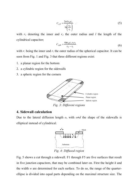
with r 1 being the inner and r 2 the outer radius of the spherical capacitor. It can be<br />
seen from Fig. 1 and Fig. 3 that three different regions exist:<br />
1. a planar region <strong>for</strong> the bottom<br />
2. a cylindric region <strong>for</strong> the sidewalls<br />
3. a spheric region <strong>for</strong> the corners<br />
(5)<br />
(6)<br />
4. Sidewall calculation<br />
Fig. 3: Different regions<br />
Cylindric region<br />
Planar region<br />
Spheric region<br />
Due to the lateral diffusion length o, with o≠d the shape of the sidewalls is<br />
elliptical instead of cylindrical.<br />
o<br />
Mask<br />
d<br />
<strong>Substrate</strong><br />
Fig. 4: Diffused region<br />
Fig. 5 shows a cut through a sidewall. F1 through F5 are five surfaces that result<br />
in five junction capacitors, that may be combined later on. First the height h and<br />
the width w are determined <strong>for</strong> each surface. To do so, the range of the quarterellipse<br />
is divided into equal parts depending on the maximal structure size. The