Accurate Junction Capacitance Modeling for Substrate Crosstalk ...
Accurate Junction Capacitance Modeling for Substrate Crosstalk ...
Accurate Junction Capacitance Modeling for Substrate Crosstalk ...

Create successful ePaper yourself
Turn your PDF publications into a flip-book with our unique Google optimized e-Paper software.
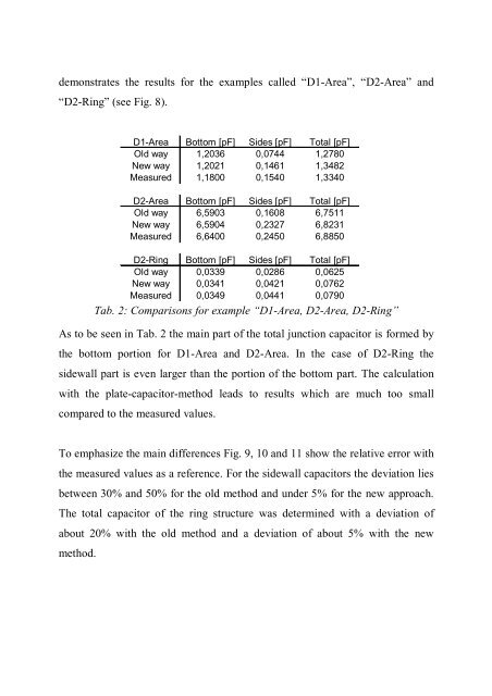
demonstrates the results <strong>for</strong> the examples called “D1-Area”, “D2-Area” and<br />
“D2-Ring” (see Fig. 8).<br />
D1-Area Bottom [pF] Sides [pF] Total [pF]<br />
Old way 1,2036 0,0744 1,2780<br />
New way 1,2021 0,1461 1,3482<br />
Measured 1,1800 0,1540 1,3340<br />
D2-Area Bottom [pF] Sides [pF] Total [pF]<br />
Old way 6,5903 0,1608 6,7511<br />
New way 6,5904 0,2327 6,8231<br />
Measured 6,6400 0,2450 6,8850<br />
D2-Ring Bottom [pF] Sides [pF] Total [pF]<br />
Old way 0,0339 0,0286 0,0625<br />
New way 0,0341 0,0421 0,0762<br />
Measured 0,0349 0,0441 0,0790<br />
Tab. 2: Comparisons <strong>for</strong> example “D1-Area, D2-Area, D2-Ring”<br />
As to be seen in Tab. 2 the main part of the total junction capacitor is <strong>for</strong>med by<br />
the bottom portion <strong>for</strong> D1-Area and D2-Area. In the case of D2-Ring the<br />
sidewall part is even larger than the portion of the bottom part. The calculation<br />
with the plate-capacitor-method leads to results which are much too small<br />
compared to the measured values.<br />
To emphasize the main differences Fig. 9, 10 and 11 show the relative error with<br />
the measured values as a reference. For the sidewall capacitors the deviation lies<br />
between 30% and 50% <strong>for</strong> the old method and under 5% <strong>for</strong> the new approach.<br />
The total capacitor of the ring structure was determined with a deviation of<br />
about 20% with the old method and a deviation of about 5% with the new<br />
method.