Datasheet - PMCCatalogue
Datasheet - PMCCatalogue
Datasheet - PMCCatalogue

You also want an ePaper? Increase the reach of your titles
YUMPU automatically turns print PDFs into web optimized ePapers that Google loves.
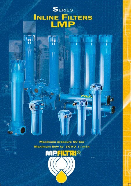
SERIES<br />
INLINE FILTERS<br />
LMP<br />
Maximum pressure 60 bar<br />
Maximum flow to 3 0 0 0 l / mi n<br />
s . p . a<br />
R
Foreword<br />
Filters are essential components in hydraulic systems since they perform a role of primary importance “Cleaning of the fluid”.<br />
Hydraulic systems require filtration products in order to reduce and maintain particulate contamination in-line with the ISO 4406<br />
cleanliness code.<br />
In-line filters in single and duplex designs are designed and built to meet market demands for applications in high pressure,<br />
Off-Line and in-line hydraulic systems.<br />
Studies conducted by our R&D department on filter bodies and filter elements led to the development of a line of products<br />
offering excellent technical features including a reduction in pressure drops combined with<br />
high dirt holding capacity of the filter elements.<br />
The choice of filter for a given application must take into account the technical characteristics of the hydraulic system and its<br />
components in relation to the work to be performed.<br />
Filter selection and sizing parameters<br />
1. Application type<br />
2. Type of filter(s)<br />
3. Sensitivity of components: to ISO 4406 class x/x/x<br />
4. Filtration efficiency: µm β x (c) ≥ 1.000<br />
5. Fluid type: HLP - HFC - HFD others<br />
6. Kinematic viscosity: mm 2 /sec (cSt)<br />
7. Operating temperature: min - max °C (°K)<br />
8. Working pressure: bar (MPa)<br />
9. Effective flow rate: l/min<br />
10. Maximum pressure drop: Δp bar (MPa)<br />
11. Bypass valve: with / without<br />
12. Differential indicator: pressure differential type Δp bar (MPa)<br />
4
Index<br />
Head at top<br />
In-line connection<br />
Series LMP400<br />
LMP900<br />
Head at top<br />
90° connection<br />
Series LMP401<br />
LMP901<br />
Head at bottom<br />
In-line connection<br />
Series LMP430<br />
LMP950<br />
Head at bottom<br />
90° connection<br />
Series LMP431<br />
LMP951<br />
INDEX<br />
Foreword<br />
Filter elements<br />
Sizing<br />
Differential indicators<br />
SAE flanges<br />
Page<br />
6<br />
8<br />
10<br />
12<br />
19<br />
FILTER<br />
LMP 400<br />
LMD 400/01/31<br />
LMP 900<br />
LMP 902-906<br />
LMP 950<br />
LMP 952-956<br />
LMD 951-953<br />
In-line filter working pressure<br />
In-line filter working pressure<br />
In-line filter working pressure<br />
In-line filter working pressure<br />
In-line filter working pressure<br />
In-line filter working pressure<br />
In-line duplex filter working pressure<br />
60/50 bar<br />
16 bar<br />
30 bar<br />
25 bar<br />
30 bar<br />
25 bar<br />
16 bar<br />
20<br />
32<br />
44<br />
54<br />
62<br />
70<br />
82<br />
Fixing accessories<br />
Operation and maintenance<br />
94<br />
96<br />
5
Foreword<br />
Installation in open circuits:<br />
Positioning<br />
Return filter mounted externally from the tank<br />
For large size systems.<br />
For flushing systems.<br />
Off-line filter<br />
For fluid power plants.<br />
For test benches.<br />
Over-boost filter<br />
Positioning between the boost pump and piston<br />
pump.<br />
Installations in closed circuits with the following<br />
functions:<br />
Working filter: down-stream from the hydrostatic transmission<br />
boost pump.<br />
Installations in forced lubrication circuits:<br />
In-line filter for low and medium pressures: protection of<br />
individual components or actuator.<br />
6
Hydraulic schematics<br />
HYDRAULIC SCHEMATICS<br />
Style S<br />
Style B<br />
B<br />
B<br />
D.I.<br />
D.I.<br />
A<br />
Filter without bypass valve, the entire flow must pass through<br />
the cartridge for maximum protection of the system in all<br />
operating conditions.<br />
A<br />
Filter with bypass valve, standard opening Δp 3.5 bar,<br />
filtration cannot be assured in all operating conditions. The<br />
flow that passes through the bypass valve is proportional to<br />
the differential pressure caused by clogging of the cartridge<br />
and variations in fluid viscosity related to temperature<br />
(see cold starts).<br />
Manifold<br />
version<br />
Duplex<br />
filter<br />
D.I. D.I. D.I.<br />
Filters with or without bypass valves, standard opening<br />
Δp 3.5 bar, mounted in parallel on 2 to 6 position<br />
multiple manifolds.<br />
Single differential indicator required.<br />
Duplex filter with or without bypass valve, standard<br />
opening Δp 3.5 bar.<br />
Two differential clogging indicators required.<br />
The filter is composed of a ball valve on the inlet connection,<br />
in 3-way execution layout “L” negative overlap, balancing<br />
connection between the two filters and double check valve on<br />
the outlet connection.<br />
7
Filter elements<br />
Description<br />
The filter elements are available with surface and depth<br />
filtration media.<br />
Surface media are made of stainless steel wire mesh,<br />
nominal filtration.<br />
Depth filtration media are made of inorganic fibre<br />
impregnated with epoxy resins, absolute filtration.<br />
Differential collapse pressure<br />
Mesh M<br />
Fibre A<br />
Cellulose P<br />
Mesh M<br />
Fibre A<br />
Δp 20 bar<br />
Δp 20 bar<br />
Δp 20 bar<br />
Δp 20 bar<br />
Δp 20 bar<br />
Serie N<br />
Serie N<br />
Serie N<br />
Serie W<br />
Serie W<br />
Support tubes - steel with heat-chemical treatment.<br />
Inner support tube - steel with heat-chemical treatment.<br />
Compatibility with fluids and filter elements<br />
Series N<br />
Composition of filtration media<br />
Series N-W: mesh M (style M25)<br />
Internal support mesh, filtration mesh, external support<br />
mesh.<br />
Series N-W: Fibre A<br />
Internal support mesh, filter media support,<br />
filtration media, prefilter media, external support mesh.<br />
Series N: Cellulose P<br />
Internal support mesh, cellulose filtration media,<br />
external support mesh.<br />
Reference standards<br />
All filter elements comply with the following<br />
ISO standards.<br />
I S O<br />
I S O<br />
I S O<br />
I S O<br />
I S O<br />
I S O<br />
I S O<br />
2941<br />
- Collapse and burst resistance<br />
2942<br />
- Bubble point test resistance.<br />
2943 - Compatibility with fluids.<br />
3723 - Resistance to axial deformation.<br />
3724 - Fatigue test with flow.<br />
3968 - Pressure drop.<br />
16889 - Filtration efficiency by means of Multipass.<br />
• The filter elements are compatible with:<br />
Mineral oils to ISO 2943 - 4<br />
Synthetic fluids.<br />
• Seals, standard in NBR compatible with:<br />
Mineral oils to ISO 2943 - 4<br />
Synthetic fluids.<br />
• FPM seals (test to ISO 2943), compatible with:<br />
Synthetic fluids type HS-HFDR-HFDS-HFDU<br />
To ISO 6743 - 4.<br />
Compatibility with fluids and W series<br />
filter elements<br />
Outer<br />
support<br />
mesh<br />
Prefilter<br />
media<br />
Inorganic microfibre<br />
Microfibre filtration media<br />
Inner support mesh<br />
Internal support<br />
Support<br />
tube<br />
• The filter elements are compatible with:<br />
Mineral oils to ISO 2943 - 4<br />
Aqueous emulsions<br />
Synthetic fluids, water and glycol.<br />
• Seals, standard in NBR compatible with:<br />
Mineral oils to ISO 2943 - 4<br />
Aqueous emulsions<br />
Synthetic fluids, water and glycol.<br />
• FPM seals (test to ISO 2943), compatible with:<br />
Synthetic fluids type HS-HFDR-HFDS-HFDU<br />
To ISO 6743 - 4.<br />
N . B. P series cellulose cartridges are compatible only with<br />
mineral oils to ISO 2943 - 4.<br />
8
Multipass test<br />
in compliance with new ISO 16889standard.<br />
Contaminant ISO MTD<br />
Multipass test<br />
in compliance with original<br />
ISO 4572 standard.<br />
Contaminant ACFTD<br />
Value β 2 10 75 100 200 1000 Value β 200<br />
Filtration efficiency in % 50% 90% 98.70% 99% 99.50% 99.90% Filtration efficiency in % 99.50%<br />
Filter element (µm ©) µm<br />
A03
Filter sizing<br />
C o r rect sizing of the filter must be based on a variable<br />
p r e s s u r e drop depending on the application:<br />
• re t u r n filter<br />
Δp from 0.4 to 0.6 bar<br />
• filter on lubrication lines Δp from 0.3 to 0.5 bar<br />
• o f f-line fluid power plants Δp from 0.3 to 0.4 bar<br />
• o f f-line filter test benches Δp from 0.1 to 0.3 bar<br />
• o v e r-boost filter<br />
Δp from 0.4 to 0.6 bar<br />
The pre s s u r e drop calculation is per f o r med by adding<br />
together the value for the housing and the value for the<br />
filter element.<br />
The pre s s u r e drop in the housing is pro p o r tional to the<br />
fluid density kg/dm 3 ; all the graphs in the catalogue are<br />
re f e r red to mineral oil with density of 0.86 kg/dm 3 .<br />
The filter element pre s s u r e drop value is pro p o r t i o n a l<br />
to viscosity mm 2 /s, the Y values in the catalogue are<br />
re f e r red to viscosity of 30 mm 2 /s.<br />
Number of working cart r i d g e s<br />
installed in LMP - LMD filters<br />
LMP 210 1 1 c a r t r i d g e CU 210 1<br />
LMP 210 2 1 c a r t r i d g e CU 210 2<br />
LMP 210 3 1 c a r t r i d g e CU 210 3<br />
L M P 40 0 2 1 c a r t r i d g e CU 400 2<br />
L M P 40 0 3 1 c a r t r i d g e CU 400 3<br />
L M P 40 0 4 1 c a r t r i d g e CU 400 4<br />
L M P 40 0 5 1 c a r t r i d g e CU 400 5<br />
L M P 40 0 6 1 c a r t r i d g e CU 400 6<br />
LMD 400/401 4 1 c a r t r i d g e CU 400 4<br />
LMD 431 5 1 c a r t r i d g e CU 400 5<br />
LMD 431 6 1 c a r t r i d g e CU 400 6<br />
L M P 900 1 1 c a r t r i d g e CU 900<br />
L M P 900 2 2 c a r t r i d g e s CU 900<br />
L M P 902 2 4 c a r t r i d g e s CU 900<br />
L M P 903 2 6 c a r t r i d g e s CU 900<br />
L M P 950 2 1 c a r t r i d g e CU 950 2<br />
L M P 950 3 1 c a r t r i d g e CU 950 3<br />
L M P 952 3 2 c a r t r i d g e s CU 950 3<br />
L M P 953 3 3 c a r t r i d g e s CU 950 3<br />
L M P 954 3 4 c a r t r i d g e s CU 950 3<br />
L M P 955 3 5 c a r t r i d g e s CU 950 3<br />
L M P 956 3 6 c a r t r i d g e s CU 950 3<br />
L M D 951 3 1 c a r t r i d g e s CU 950 3<br />
L M D 952 3 2 c a r t r i d g e s CU 950 3<br />
L M D 953 3 3 c a r t r i d g e s CU 950 3<br />
Filter h o u s i n g Δp pressure drop<br />
The curves are plotted utilising mineral oil<br />
with density of 0.86 kg/dm 3 to ISO 3968.<br />
Δp varies proportionally with density.<br />
LMP 900 - 901<br />
F1 - 3” - Δp housing<br />
0 , 6 0<br />
0 , 4 5<br />
0 , 3 0<br />
0 , 1 5<br />
9 0 0<br />
F1 - 3”<br />
0 , 00<br />
0 30 0 60 0 90 0 12 00 15 00<br />
Flow rate l/min<br />
For Y values see next page:<br />
10<br />
9 0 1<br />
F1 - 3”<br />
Sizing data for single cartridge,<br />
head at top<br />
Δp Tot.<br />
Δpc Filter h o u s i n g<br />
Δpe Filter element<br />
Y Multiplication factor (see page 11)<br />
Q l/min = flow rate<br />
V1 = reference viscosity 30 mm 2 /s (cSt)<br />
V2 = operating viscosity in mm 2 /s (cSt)<br />
Δp Tot. = Δpc + Δpe<br />
Δpe = Y : 1000 x Q x (V2/V1)<br />
Calculation example with HLP Mineral Oil<br />
Variation in viscosity<br />
D a t a :<br />
Filter with in-line connections<br />
P r e s s u r e = 15 bar<br />
Flow rate = 700 l/min<br />
Viscosity = 46 mm 2 /s (cSt)<br />
Density = 0.86 kg/dm 3<br />
Filtration = 10 µ absolute<br />
With bypass valve<br />
Filter type - LMP 900 1 (see housings pressure drop<br />
graphs on page 52)<br />
Practical example<br />
Q<br />
= 700 l/min<br />
V 2 = 46 mm 2 /s (cSt)<br />
Pmax = 15 bar<br />
Filtration = 10 µ absolute<br />
Δp Tot. max = 0.6 bar (max. recommended value)<br />
Filter element series N, Δp max 20 bar<br />
Δpc = 0.13 bar (* see diagram)<br />
Δpe = (0.3166 : 1000) x 700 x (46/30) = 0.34 bar<br />
Δp Tot. = 0.13 + 0.34 = 0.47 bar<br />
Sized filter type:<br />
LMP 900 1 B A F1 A10 N P01<br />
Calculation examples with HFD fluid<br />
Variations in viscosity and density<br />
D a t a :<br />
Filter with in-line connections<br />
P r e s s u r e = 15 bar<br />
Flow rate = 700 l/min<br />
Viscosity = 46 mm 2 /s (cSt)<br />
Density = 1.1 kg/dm 3<br />
Filtration = 10 µ absolute<br />
With bypass valve<br />
Filter type - LMP 900 1 (see housings pressure drop<br />
graphs on page 52)<br />
Practical example<br />
Q<br />
= 700 l/min<br />
V 2<br />
= 46 mm 2 /s (cSt)<br />
Pmax = 15 bar<br />
Filtration = 10 µ absolute<br />
Δp Tot. max = 0.6 bar (max. recommended value)<br />
Filter element series N, Δp max 20 bar<br />
Δpc = 0.13 x (1.1/0.86)= 0.17<br />
Δpe = (0.3166 : 1000) x 700 x (46/30) = 0.34 bar<br />
Δp Tot. = 0.17 + 0.34 = 0.51 bar<br />
Filter type:<br />
LMP 900 1 B V F1 A10 N P01
Data for sizing multicartridge<br />
filters with head at top<br />
Δp Tot.<br />
Δpc Filter housing<br />
Δpe Filter element<br />
Y Multiplication factor (see below)<br />
Q l/min = flow rate<br />
V1 = reference viscosity 30 mm 2 /s (cSt)<br />
V2 = operating viscosity in mm 2 /s (cSt)<br />
Δp Tot. = Δpc + Δpe<br />
Δpe = Y : 1000 x Q x (V2/V1)<br />
For multicartridge filter sizing, the value of flow rate “Q l/min”<br />
must be divided by the number of cartridges.<br />
Calculation example with HLP Mineral Oil<br />
Variation in viscosity<br />
D a t a :<br />
Filter with in-line connections<br />
P r e s s u r e = 10 bar<br />
Flow rate = 1400 l/min<br />
Viscosity = 46 mm 2 /s (cSt)<br />
Density = 0.86 kg/dm 3<br />
Filtration = 6 µ absolute<br />
With bypass valve<br />
Filter type - LMP 952 number of installed cartridges 2<br />
(see housings pressure drop graphs on pages 78 to 79)<br />
Practical example<br />
Calculation examples with HFD fluid<br />
Variations in viscosity and density<br />
D a t a :<br />
Filter with in-line connections<br />
P r e s s u r e = 10 bar<br />
Flow rate = 1400 l/min<br />
Vi s c o s i t y = 46 mm 2 /s (cSt)<br />
Density = 1.1 kg/dm 3<br />
F i l t r a t i o n = 6 µ absolute<br />
With bypass valve<br />
Filter type - LMP 952<br />
(see housings pressure drop graphs on pages 78 to 79)<br />
Practical example<br />
Q<br />
= 1400 l/min<br />
V 2 = mm 2 /s (cSt)<br />
Pmax = 10 bar<br />
Filtration = 6 µ absolute<br />
Δp Tot. max = 0.6 bar (max. recommended value)<br />
Filter element series N, Δp max 20 bar<br />
Δpc = 0.1 x (1.1/0.86)= 0.127 bar<br />
Δpe = (0.4 : 1000) x (1400/2) x (46/30) = 0.43 bar<br />
Δp Tot. = 0.127 + 0.43 = 0.557 bar<br />
Filter type:<br />
LMP 952 B V F3 A06 N P01<br />
Filter housing Δp pressure drop<br />
The curves are plotted utilising mineral oil<br />
with density of 0.86 kg/dm 3 to ISO 3968.<br />
Δp varies proportionally with density.<br />
Q<br />
= 1400 l/min<br />
V 2 = 46 mm 2 /s (cSt)<br />
Pmax = 10 bar<br />
Filtration = 6 m absolute<br />
Δp Tot. max = 0.6 bar (max. recommended value)<br />
Filter element series N, Δp max 20 bar<br />
Δpc = 0.1 bar (* see diagram)<br />
Δpe = (0.4 : 1000) x (1400/2) x (46/30) = 0.43 bar<br />
Δp Tot. = 0.1 + 0.43 = 0.53 bar<br />
Sized filter type:<br />
LMP 952 B A F3 A06 N P01<br />
Multiplication factor “Y” for definition of the<br />
p re s s u re drop of filter elements.<br />
R e f e r ence viscosity 150 SUS<br />
0 , 45<br />
0 , 36<br />
0 , 27<br />
0 , 18<br />
0 , 09<br />
0 , 00<br />
LMP 952<br />
95 2<br />
0 50 0 10 00 15 00 20 00 25 00 30 00<br />
Flow rate l/min<br />
F i l t e r<br />
E l e m e n t<br />
Type<br />
CU 210 1<br />
2<br />
3<br />
CU 400 2<br />
3<br />
4<br />
5<br />
6<br />
CU 900 1<br />
CU 950 2<br />
3<br />
F i l t r a t i o n<br />
Serie N - W<br />
Serie N<br />
A 0 3 A 0 6 A 1 0 A 1 6 A 2 5 M 2 5 P 1 0 P 2 5<br />
5,3<br />
3<br />
1,55<br />
3,133<br />
2,150<br />
1,600<br />
1,000<br />
0,822<br />
0,860 0,6333 0,3166 0,300 0,2142 0,050<br />
1,030<br />
0,443<br />
3,92<br />
2,3<br />
1,33<br />
2,550<br />
1,700<br />
1,285<br />
0,833<br />
0,580<br />
0,8<br />
0,4<br />
1,9<br />
1,21<br />
0,69<br />
1,457<br />
0,940<br />
0,709<br />
0,475<br />
0,300<br />
0,5875<br />
0,2625<br />
1,66<br />
0,88<br />
0,49<br />
1,225<br />
0,781<br />
0,615<br />
0,340<br />
0,267<br />
0,4<br />
0,1833<br />
1,2<br />
0,68<br />
0,42<br />
0,780<br />
0,500<br />
0,400<br />
0,200<br />
0,175<br />
0,2571<br />
0,152<br />
0,098<br />
0,065<br />
0,049<br />
0,192<br />
0,102<br />
0,084<br />
0,057<br />
0,053<br />
0,050<br />
0,020<br />
0,48<br />
0,42<br />
0,23<br />
0,750<br />
0,400<br />
0,340<br />
0,240<br />
0,220<br />
-<br />
-<br />
0,41<br />
0,35<br />
0,17<br />
0,640<br />
0,340<br />
0,270<br />
0,190<br />
0,177<br />
-<br />
-<br />
1 1
Differential indicators<br />
A guarantee of maintenance of the correct ISO 4406 contamination class achieved through the use of the filters can be provided<br />
exclusively with the correct use of the specific differential indicators.<br />
The trip threshold of the indicator must be selected taking account of the maximum differential pressure indicated for each type<br />
of filter element and the trip pressure of the bypass valve, if incorporated in the filter.<br />
Indicator housing ( M a t e r i a l s )<br />
• Brass<br />
P r e s s u r e<br />
• Max. working pre s s u re : 420 bar (42 MPa)<br />
Te m p e r a t u re<br />
• From -35°C to +110°C<br />
S e a l s<br />
• HNBR<br />
• FPM<br />
C o m p a t i b i l i t y<br />
• Housings compatible with:<br />
Mineral oils to ISO 2943 - aqueous emulsions<br />
Synthetic fluids, water and glycol.<br />
• V and H series FPM and HNBR seals, compatible with:<br />
Mineral oils to ISO 2943 - aqueous emulsions<br />
Synthetic fluids, water and glycol.<br />
For synthetic fluids type HS-HFDR-HFDS-HFDU,<br />
series V FPM seals.<br />
1 2
1 3<br />
Order code<br />
Order code<br />
1 2 3 4<br />
1 2 3 4 5 6 7 8<br />
Example: 1 E 7<br />
Example: NM 8 C 11 P01<br />
1 - Differential trip pressure<br />
1 1,2 bar ± 10% (only for style V - E)<br />
2 - Styles<br />
V Visual<br />
1 - Styles<br />
NR Electrical<br />
KR Electrical-Visual<br />
NM Electrical IP 67<br />
E<br />
Electrical-Visual<br />
Z<br />
Visual<br />
J Electrical-Visual-Thermostat controlled<br />
3 - Differential trip pressure<br />
6 2 bar ± 10%<br />
7 5 bar ± 10%<br />
4 - Seals<br />
FPM Standard<br />
x Others on request<br />
Seal for indicator/filter head, Bonded Seal.<br />
N<br />
K<br />
NE<br />
Electrical<br />
Electrical-Visual<br />
Electronic<br />
2 - Differential trip pressure<br />
2 1,2 bar ± 10%<br />
6 2 bar ± 10%<br />
7 5 bar ± 10%<br />
3 - Power supply voltage*<br />
(only for style K - KR)<br />
1 24 Volt<br />
4 - Seals<br />
2 110 Volt (only DC voltage for KR style)<br />
3 220 Volt (excluding style KR)<br />
ADAPTER<br />
Order code<br />
ICPAP01<br />
H<br />
V<br />
x<br />
HNBR Standard<br />
FPM<br />
Others on request<br />
5 - Thermostat (only for style NM)<br />
A<br />
Without<br />
C 50°<br />
6 - Electrical connector (only for style NM)<br />
11 AMP Superseal connector<br />
7 - Opzioni (only for style NE)<br />
CLOGGING INDICATOR SELECTION<br />
Filter for forced lubrication with or without bypass indicator<br />
opening value Δp 1.2 - Δp 2 bar.<br />
S<br />
T<br />
8 - Options<br />
Standard<br />
Double contact 75% - 100%<br />
6 sec. signalling delay<br />
Return or in-line filter with bypass valve indicator opening<br />
value Δp 2 bar.<br />
P 0 1<br />
MP standard<br />
Off-line and over-boost filter, without bypass valve indicator<br />
opening value Δp 2 bar - 5 bar.<br />
Seal for indicator/filter head, flat profiled.<br />
* Other power supply voltages on request.
Differential indicator dimensions<br />
35<br />
Ch. 30<br />
Ch. 32<br />
Ch. 30<br />
SERIES Z<br />
43,5<br />
SERIES V<br />
SERIES NR - KR<br />
44<br />
Ch. 32 Ch. 32<br />
SERIES E<br />
SERIES J<br />
Ch. 27<br />
SERIES NM con Termostato<br />
Ch. 27<br />
SERIES NM senza Termostato<br />
31<br />
32<br />
35<br />
Ch. 30<br />
Ch. 30<br />
Ch. 27<br />
SERIES N - K - NE SERIES NE...T ICPAP01<br />
1 4
STYLE<br />
TECHNICAL CHARACTERISTICS<br />
SERIES Z VISUAL<br />
Standard visual indicator with manual reset.<br />
Nylon signalling button.<br />
Button depressed position = cartridge clean.<br />
Button raised position, Red = cartridge clogged.<br />
Weight: 118 g.<br />
Tightening torque:<br />
65 Nm.<br />
SERIES V VISUAL<br />
Cover and lens in nylon.<br />
Visual indicator green<br />
Visual indicator red<br />
= cartridge clean.<br />
= cartridge clogged.<br />
Weight: 137 g.<br />
Tightening torque:<br />
95 Nm.<br />
SERIES E<br />
ELECTRICAL/VISUAL<br />
Connector EN 175301-803 A/ISO 4400<br />
Protection rating IP 65<br />
Max. contact rating 5 A/250V ~<br />
Power supply voltage 230 V ~<br />
3<br />
2<br />
N.C.<br />
N.O.<br />
2<br />
3<br />
Connector<br />
DIN 43650 Microswitch contact<br />
Cablegland PG 9<br />
Cover and lens in nylon.<br />
Visual indicator green<br />
Visual indicator red<br />
= cartridge clean.<br />
= cartridge clogged.<br />
1<br />
1<br />
Weight: 188 g.<br />
Tightening torque:<br />
95 Nm.<br />
SERIES J ELECTRICAL/VISUAL WITH THERMOSTAT CONTROL<br />
Connector EN 175301-803 A/ISO 4400<br />
Protection rating IP 65<br />
Max. contact rating 5 A/250V ~<br />
Power supply voltage 230 V ~<br />
Connector<br />
DIN 43650 Microswitch contact<br />
Cable gland PG 9<br />
Cover and lens in nylon<br />
3<br />
2<br />
1<br />
N.C.<br />
N.O.<br />
T 30°C<br />
2<br />
3<br />
1<br />
Visual indicator green<br />
= cartridge clean.<br />
Visual indicator red<br />
= cartridge clogged.<br />
CONTACT<br />
N.O.<br />
Operation on reaching temperature of +30°C<br />
Weight: 198 g.<br />
Tightening torque:<br />
95 Nm.<br />
1 6
STYLE<br />
TECHNICAL CHARACTERISTICS<br />
SERIES K<br />
ELECTRICAL/VISUAL<br />
Connector EN 175301-803 A/ISO 4400<br />
Protection rating P 65<br />
Max. contact rating 5 A/250V ~<br />
Power supply voltage<br />
24V DC - 115V DC/AC - 230V AC<br />
3<br />
2 N.C.<br />
2<br />
N.O.<br />
3<br />
LED<br />
1<br />
4<br />
1<br />
Connector<br />
DIN 43650 Microswitch contact<br />
Cable gland PG 9<br />
SIGNALLING LEDS<br />
GREEN LED<br />
= Cartridge clean.<br />
RED LED<br />
= Cartridge clogged.<br />
We i g h t : 183 g.<br />
Tightening torq u e :<br />
65 Nm.<br />
SERIES N ELECTRICAL<br />
Connector EN 175301-803 A/ISO 4400<br />
Protection rating IP 65<br />
Max. contact rating 5 A/250V ~<br />
Power supply voltage 230 V ~<br />
3<br />
2<br />
N.C.<br />
N.O.<br />
2<br />
3<br />
1<br />
Connector<br />
DIN 43650 Microswitch contact<br />
Cable gland PG 9<br />
We i g h t : 183 g.<br />
Tightening torq u e :<br />
65 Nm.<br />
1<br />
SERIES KR ELECTRICAL/VISUAL<br />
Connector EN 175301-803 A/ISO 4400<br />
Protection rating IP 65<br />
Max. contact rating 0.8 A/24V DC<br />
0.17 A/115V DC<br />
Power supply voltage 24V - 115V DC<br />
3<br />
2 N.C.<br />
2<br />
N.O.<br />
3<br />
LED<br />
1<br />
4<br />
1<br />
Connector<br />
DIN 43650 Reed switch<br />
Cable gland PG 9<br />
SIGNALLING LEDS<br />
GREEN LED<br />
RED LED<br />
Weight : 123 g.<br />
Tightening torq u e :<br />
= Cartridge clean.<br />
= Cartridge clogged.<br />
65 Nm.<br />
SERIES NR ELECTRICAL<br />
Connector EN 175301-803 A/ISO 4400<br />
2<br />
3<br />
N.C.<br />
N.O.<br />
2<br />
3<br />
Protection rating IP 65<br />
Max. contact rating<br />
0.17 A/115V DC<br />
Max power supply voltage 1 max 120V DC<br />
Connector<br />
DIN 43650 Reed switch<br />
Cable gland PG 9<br />
1<br />
Weight : 123 g.<br />
1<br />
Tightening torq u e :<br />
65 Nm.<br />
SERIES NM.A ELECTRICAL<br />
Connector<br />
AMP Superseal<br />
Cable and cablegland<br />
PVC<br />
Max. contact rating<br />
0.17 A/115V DC<br />
Max power supply voltage max 120V DC<br />
Protection rating IP 67<br />
Contacts<br />
N.O.<br />
Weight : 110 g.<br />
Tightening torq u e :<br />
65 Nm.<br />
1 7
STYLE<br />
TECHNICAL CHARACTERISTICS<br />
SERIES NM.C ELECTRICAL/THERMOSTAT<br />
Connector<br />
AMP Superseal<br />
Cable and cable gland<br />
PVC<br />
Max. contact rating<br />
0.17 A/115V DC<br />
Max power supply voltage<br />
max 120V DC<br />
Protection rating IP 67<br />
N.O. Contacts<br />
Thermostat (N.O.)<br />
Switching +50°C<br />
T 50°C<br />
Weight : 136 g.<br />
Tightening torq u e :<br />
65 Nm.<br />
SERIES NE ELECTRONIC<br />
1= + 24 VCC<br />
2= Out 4 - 20 mA<br />
3= - 24 VCC<br />
3<br />
2<br />
1<br />
Protection rating IP 65<br />
Power supply voltage from<br />
19 to 28 VCC<br />
Output signal<br />
4 - 20 mA<br />
Input impedance<br />
100 Ohm<br />
Non-linearity + hysteresis<br />
≤10% of full scale<br />
Thermal deviation from zero<br />
< 5 % of full scale from 0°C to +60°C<br />
Operating temperature<br />
from -20°C to +80°C<br />
Storage temperature<br />
from -35°C to +110°C<br />
Connector DIN 43650<br />
Cable gland PG 9<br />
We i g h t : 200 g.<br />
Tightening torq u e :<br />
65 Nm.<br />
INDICATOR NE...T ELECTRONIC<br />
1= + 24 VCC<br />
2= Out 4 > 20 mA<br />
3= Out N.O. 20 mA<br />
4= Out N.O. 16 mA<br />
5= - 24 VCC<br />
4<br />
5<br />
3<br />
1 2<br />
Protection rating IP 67<br />
Power supply voltage from<br />
19 to 28 VCC<br />
Output signal<br />
4 - 20 mA<br />
Input impedance<br />
100 Ohm<br />
Non-linearity + hysteresis<br />
≤10% of full scale<br />
Thermal deviation from zero<br />
< 5% of full scale from 0°C to +70°C<br />
N° 1 N.O. alarm threshold 16 mA (75% of full scale)<br />
N° 2 N.O. alarm threshold 20 mA (100% of full scale)<br />
Fixed timer interval<br />
thresold N° 1 and N° 2 6 seconds<br />
Operating temperature<br />
from -20°C to +80°C<br />
Storage temperature<br />
from -35°C to +110°C<br />
Connector M12 5 pin IEC 60947-5-2<br />
We i g h t : 350 g.<br />
Tightening torq u e :<br />
65 Nm.<br />
ADAPTER ICPAP01<br />
IN<br />
OUT<br />
Adapter for oil outlet and pressure sensing up-stream and down-stream from<br />
the filter element.<br />
IN/OUT connections G 1/4”<br />
Orientation of IN/OUT connections 360°<br />
Material: Phosphated stainless steel<br />
Seals: NBR (others on request)<br />
1 8
Sizes / Connections to SAE flange<br />
FLANGE SAE 3000 PSI<br />
E Depth<br />
A<br />
D<br />
B<br />
Connection to 3000 psi SAE flange<br />
Dimension<br />
2”<br />
SAE<br />
3000 PSI<br />
M<br />
2”<br />
SAE<br />
3000 PSI<br />
UNC<br />
2 1/2”<br />
SAE<br />
3000 PSI<br />
M<br />
2 1/2”<br />
SAE<br />
3000 PSI<br />
UNC<br />
3”<br />
SAE<br />
3000 PSI<br />
M<br />
3”<br />
SAE<br />
3000 PSI<br />
UNC<br />
4”<br />
SAE<br />
3000 PSI<br />
M<br />
4”<br />
SAE<br />
3000 PSI<br />
UNC<br />
A<br />
51<br />
51<br />
63<br />
63<br />
73<br />
73<br />
99<br />
99<br />
B<br />
77,77<br />
77,77<br />
88,90<br />
88,90<br />
106,38<br />
106,38<br />
130,18<br />
130,18<br />
C<br />
42,88<br />
42,88<br />
50,80<br />
50,80<br />
61,93<br />
61,93<br />
77,77<br />
77,77<br />
D<br />
M12<br />
1/2” UNC<br />
M12<br />
1/2” UNC<br />
M16<br />
5/8” UNC<br />
M16<br />
5/8” UNC<br />
E<br />
20<br />
20<br />
20<br />
20<br />
25<br />
25<br />
25<br />
25<br />
FLANGE DIN PN 16<br />
G<br />
C o n n e c t i o n<br />
Flange IN-OUT<br />
DIN<br />
PN16<br />
DN80<br />
DIN<br />
PN16<br />
DN100<br />
A<br />
73<br />
99<br />
A<br />
E<br />
F<br />
E<br />
F<br />
G<br />
160<br />
200<br />
18<br />
180<br />
220<br />
18<br />
SAE flange connections available on in-Line filters<br />
Filter<br />
SAE 3000 PSI<br />
DIN PN16<br />
Type<br />
2 ” 2 1 / 2 ” 3 ” 4 ”<br />
DN80<br />
DN100<br />
LMP400/1<br />
X<br />
X<br />
LMP430/1<br />
X<br />
X<br />
LMD400/1/31<br />
LMP900/1<br />
LMP902/3<br />
LMP950/1<br />
X<br />
X<br />
X<br />
X<br />
X<br />
X<br />
LMP952/3/4/5/6<br />
X<br />
LMD951/2/3<br />
X<br />
X X X<br />
1 9
2 0<br />
LMP 210
SERIES<br />
LMP 210<br />
Working pressure<br />
60 bar<br />
Style S<br />
Style B<br />
B<br />
B<br />
D.I.<br />
D.I.<br />
A<br />
A<br />
2 1
Technical data<br />
Filter housing ( M a t e r i a l s )<br />
• Head: Anodised Aluminium<br />
• Housing: Anodised A l u m i n i u m<br />
• Bypass valve: Nylon<br />
P r e s s u re<br />
• Working pre s s u re: 60 bar (6 MPa)<br />
• Test pre s s u re: 90 bar (9 MPa)<br />
• Burst pre s s u re: 180 bar (18 MPa)<br />
• Pulsed pre s s u re fatigue test: 1.000.000 cycles<br />
with pre s s u re from 0 to 60 bar (6 MPa)<br />
Te m p e r a t u r e<br />
• From -25°C to +110°C<br />
Bypass valve<br />
• Opening pre s s u re 3.5 bar ±10%<br />
• Other opening pre s s u res on re q u e s t .<br />
Δp Elements type<br />
• Series N and W elements: 20 bar<br />
• Oil flow from exterior to interior.<br />
S e a l s<br />
• Standard NBR series A<br />
• Optional FPM<br />
series V<br />
Weights (kg)<br />
L e n g t h<br />
• LMP210 - 1 3.5<br />
• LMP210 -2 4.4<br />
• LMP210 - 3 5 . 4<br />
Volumes (d m 3 )<br />
L e n g t h<br />
• LMP210 - 1 1.5<br />
• LMP210 -2 2<br />
• LMP210 - 3 2.7<br />
Connections<br />
In-line Inlet/Outlet LMP 210<br />
C o m p a t i b i l i t y<br />
• Housings compatible with:<br />
Mineral oils to ISO 2943 - aqueous emulsions<br />
synthetic fluids, water and glycol.<br />
• The filter elements are compatible with:<br />
Mineral oils to ISO 2943, Synthetic fluids<br />
Aqueous emulsions, water and glycol<br />
(series W re q u i re d ).<br />
• NBR seals series A, compatible with:<br />
Mineral oils to ISO 2943 - aqueous emulsions<br />
synthetic fluids, water and glycol.<br />
• V series FPM seals, compatible with:<br />
Synthetic fluids type HS-HFDR-HFDS-HFDU<br />
To ISO 2943<br />
Filter housing Δp pressure drop<br />
The curves are plotted utilising mineral oil<br />
with density of 0.86 kg/dm 3 to ISO 3968.<br />
Δp varies proportionally with density.<br />
0 , 9<br />
0 , 6<br />
0 , 3<br />
0 , 0 0<br />
Valves<br />
5 , 4 0<br />
3 , 6 0<br />
1 , 8 0<br />
0 , 0 0<br />
LMP 210 - Δp Housing<br />
0 60 12 0 18 0 24 0 30 0<br />
Flow rate l/min<br />
Bypass valve pressure drop<br />
Type<br />
A<br />
B<br />
C<br />
LMP 210<br />
A<br />
A<br />
B<br />
C<br />
B / C<br />
0 60 12 0 18 0 24 0 30 0<br />
Flow rate l/min<br />
Filter housing and valves Δp pressure drop connection<br />
Connection<br />
(dimensions page 23)<br />
G1 - G4 - G7- F1 - F4<br />
G2 - G5 - G8 - F2 - F5<br />
G3 - G6 - G9 - F3 - F6<br />
Bypass valve<br />
Recommended maximum flow rate<br />
- Pre s s u re drop of filter assembly equal to Δp 0,6 bar.<br />
- Oil kinematic viscosity 30 mm 2/s ( s C t ).<br />
- Density 0,86 kg/dm 3 .<br />
- Connections of filter under test G 3”.<br />
Filter Flow rate l/min Series N<br />
e l e m e n t Filter lenght<br />
type 1 2 3<br />
2 2<br />
Filter Element Area<br />
Filter element in stainless steel mesh<br />
Length<br />
Type<br />
1 2 3<br />
CU 210 3100 4950 7520<br />
Values expressed in cm 2<br />
A 03 98 140 190<br />
A 06 120 162 200<br />
A 10 175 205 235<br />
A 16 185 225 245<br />
A 25 208 235 250<br />
M 25 265 270 270<br />
P10 245 250 260<br />
P25 250 255 268
Dimensions<br />
LMP 210<br />
1 2 0<br />
B<br />
A<br />
D<br />
I N<br />
O U T<br />
I N<br />
Ø 1 0 1<br />
Ch. 30<br />
1 0<br />
Indicator port<br />
Plug T2 - Ch. 30<br />
Threaded Connections<br />
Type<br />
Connection “A”<br />
E<br />
Depth 12 mm<br />
G1<br />
G 1<br />
M 8<br />
G2<br />
G 1 1/4”<br />
M 8<br />
G3<br />
G 1 1/2”<br />
M 8<br />
G4<br />
1” NPT<br />
5/16” UNC<br />
F i x i n g<br />
h o l e s<br />
G5<br />
G6<br />
1 1/4” NPT<br />
1 1/2” NPT<br />
5/16” UNC<br />
5/16” UNC<br />
E<br />
G7<br />
SAE 16 1 5/16” 12 UN<br />
5/16” UNC<br />
9 8<br />
G8<br />
G9<br />
SAE 20 1 5/8” 12 UN<br />
SAE 24 1 7/8” 12 UN<br />
5/16” UNC<br />
5/16” UNC<br />
Filter<br />
Length<br />
1<br />
2<br />
3<br />
H<br />
mm<br />
360<br />
492<br />
630<br />
Flanged Connections<br />
Type Connection “A”<br />
F1 1” SAE - 3000 psi/M<br />
F2 1 1/4” SAE - 3000 psi/M<br />
“B”<br />
52 , 37<br />
58 , 72<br />
“C”<br />
26 , 19<br />
30 , 18<br />
“D”<br />
M 10<br />
M 10<br />
E<br />
Depth 12 mm<br />
M 8<br />
M 8<br />
F3<br />
1 1/2” SAE - 3000 psi/M<br />
6 9 , 8 5<br />
3 5 , 7 1<br />
M 1 2<br />
M 8<br />
F4<br />
1” SAE - 3000 psi/UNC<br />
5 2 , 3 7<br />
2 6 , 1 9<br />
3/8” UNC<br />
5/16” UNC<br />
F5<br />
1 1/4” SAE - 3000 psi/UNC<br />
5 8 , 7 2<br />
3 0 , 1 8<br />
7/16” UNC<br />
5/16” UNC<br />
F6<br />
1 1/2” SAE - 3000 psi/UNC<br />
6 9 , 8 5<br />
3 5 , 7 1<br />
1/2” UNC<br />
5/16” UNC<br />
2 3
LMP 210 spare parts<br />
3 c<br />
3 d<br />
4<br />
3 a<br />
1<br />
3 b<br />
2<br />
Pos.<br />
Description<br />
Qty<br />
FILTER Series LMD 401<br />
1<br />
Filter assembly<br />
1<br />
See order table<br />
2<br />
Filter element<br />
1<br />
See order table<br />
3<br />
Seals kit<br />
1<br />
NBR<br />
FPM<br />
02050435 02050436<br />
3a<br />
O-Ring filter element<br />
1<br />
O-R 144 Ø 39,69 x 3,53<br />
3b<br />
O-Ring housing<br />
1<br />
O-R 4375 Ø 94,84 x 3,53<br />
3c<br />
Seal<br />
1<br />
01030058 01030046<br />
3d<br />
O-Ring<br />
2<br />
O-R 2050 Ø 12,42 x 1,78<br />
4<br />
Indicator plug<br />
1<br />
T2H<br />
T2V<br />
-<br />
Indicators<br />
1<br />
See order table<br />
2 4
LMP 210 ordering information<br />
Filter assembly<br />
LMP210<br />
1 2 3 4 5 6<br />
7<br />
Example: LMP210 2 B A G3 A10 N P01<br />
Filter Element<br />
1 5 3 6 7<br />
CU210<br />
Example: CU210 2 A10 A N P01<br />
1 - Sizes<br />
1<br />
6 - Filter element<br />
A03 3 µm A16 16 µm<br />
Absolute filtration<br />
Inorganic<br />
microfibre<br />
2<br />
A06 6 µm A25 25 µm<br />
ßx (c) ≥ 1 0 0 0<br />
3<br />
A10 10 µm<br />
3 - Valves<br />
M25 25 µm M90 90 µm<br />
Nominal Filtration<br />
Metal mesh<br />
S<br />
Without by-pass<br />
M60 60 µm<br />
B<br />
With by-pass<br />
4 - Seals<br />
A<br />
NBR<br />
P10 10 µm<br />
P25 25 µm<br />
Nominal Filtration<br />
Cellulose<br />
V<br />
FPM<br />
7 - Filter elements series<br />
5 - Connections<br />
Threaded<br />
G 1<br />
G 1”<br />
G 2 G 1 1/4”<br />
Flanged<br />
F 1 1” SAE 3000 psi/M<br />
F 2 1 1/4” SAE 3000 psi/M<br />
N<br />
W<br />
8 - Options<br />
a - Filter<br />
Δp 20 bar<br />
Δp 20 bar Compatible with fluid FH AFH BFH C<br />
(not available for filter element Pxx)<br />
G 3<br />
G 1 1/2”<br />
F 3<br />
1 1/2” SAE 3000 psi/M<br />
P01<br />
MP Standard filters<br />
G 4<br />
1” NPT<br />
F 4<br />
1” SAE 3000 psi/UNC<br />
G 5<br />
1 1/4” NPT<br />
F 5<br />
1 1/4” SAE 3000 psi/UNC<br />
DIFFERENTIAL INDICATORS<br />
See catalogue IL LINE filter (code: CMP 1007 UK 001 B)<br />
G 6<br />
1 1/2” NPT<br />
F 6<br />
1 1/2” SAE 3000 psi/UNC<br />
G 7<br />
SAE 16 1 5/16” 12UN<br />
G 8<br />
SAE 20 1 5/8” 12UN<br />
G 9<br />
SAE 24 1 7/8” 12UN<br />
MP Filtri - The filter functions as described in this bulletin are valid exclusively for original MP Filtri filter elements and<br />
replacement parts. All rights reserved<br />
The data in this publication are purely guideline. MP Filtri reserves the right to make changes to the models described herein at any time it deems fit in relation to technical or<br />
commercial requirements. The colours of the products shown on the cover are purely guideline. Copyright. All rights reserved.<br />
2 5
2 6<br />
LMP 400 - 401<br />
430 - 431
SERIES<br />
LMP 400 - 401<br />
430 - 431<br />
Working pressure<br />
60/50 bar<br />
Style S<br />
Style B<br />
B<br />
B<br />
D.I.<br />
D.I.<br />
A<br />
A<br />
2 7
Technical data<br />
Filter h o u s i n g ( M a t e r i a l s )<br />
• Head: Anodised Aluminium<br />
• Housing: Anodised A l u m i n i u m<br />
• Bypass valve: Steel<br />
P r e s s u re<br />
LMP 400 lenght: 2 - 3 - 4<br />
• Working pre s s u re: 60 bar (6 MPa)<br />
• Test pre s s u re: 90 bar (9 MPa)<br />
• Burst pre s s u re: 180 bar (18 MPa)<br />
• Pulsed pre s s u re fatigue test: 1.000.000 cycles<br />
with pre s s u re from 0 to 60 bar (6 MPa)<br />
LMP 400 lenght: 5 - 6<br />
• Working pre s s u re: 50 bar (5 MPa)<br />
• Test pre s s u re: 75 bar (7,5 MPa)<br />
• Burst pre s s u re: 150 bar (15 MPa)<br />
• Pulsed pre s s u re fatigue test: 1.000.000 cycles<br />
with pre s s u re from 0 to 50 bar (5 MPa)<br />
Te m p e r a t u r e<br />
• From -25°C to +110°C<br />
• The filter elements are compatible with:<br />
Mineral oils to ISO 2943, Synthetic fluids<br />
Aqueous emulsions, water and glycol<br />
(series W re q u i re d ).<br />
• NBR seals series A, compatible with:<br />
Mineral oils to ISO 2943 - aqueous emulsions<br />
synthetic fluids, water and glycol.<br />
• V series FPM seals, compatible with:<br />
Synthetic fluids type HS-HFDR-HFDS-HFDU<br />
To ISO 2943<br />
Filter Element Area<br />
Filter element in stainless steel mesh<br />
Length<br />
Type 2 3 4 5 6<br />
CU 400<br />
3300 4950 6550 10200 15300<br />
Values expressed in cm 2<br />
Filter housing Δp pressure drop<br />
The curves are plotted utilising mineral oil<br />
with density of 0.86 kg/dm 3 to ISO 3968.<br />
Δp varies proportionally with density.<br />
Bypass valve<br />
• Opening pre s s u re 3.5 bar ±10%<br />
• Other opening pre s s u res on re q u e s t .<br />
0 , 9<br />
LMP 400 - 401 - Δp housing<br />
G 1 G 2 F 1<br />
F 2<br />
Δp Elements type<br />
• Series N and W elements: 20 bar<br />
0 , 6<br />
• Oil flow from exterior to interior.<br />
S e a l s<br />
• Standard NBR<br />
• Optional FPM<br />
Weights (kg)<br />
L e n g t h<br />
• LMP400 - 2 6.7<br />
• LMP400 -3 7.3<br />
• LMP400 - 4 8.1<br />
• LMP400 - 5 11.3<br />
• LMP400 - 6 14 . 4<br />
series A<br />
series V<br />
Volumes (d m 3 )<br />
L e n g t h<br />
• LMP400 - 2 3.5<br />
• LMP400 -3 5<br />
• LMP400 - 4 6.5<br />
• LMP400 - 5 9.5<br />
• LMP400 - 6 13.5<br />
Connections<br />
In-line Inlet/Outlet LMP 400 - 430<br />
90° Inlet/outlet LMP 401 - 431<br />
0 , 3<br />
0 , 00<br />
0 18 0 36 0 54 0 72 0 90 0<br />
Flow rate l/min<br />
Valves<br />
Bypass valve pressure drop<br />
LMP 400 - By-pass<br />
9<br />
6<br />
3<br />
C o m p a t i b i l i t y<br />
• H o u s i n g s compatible with:<br />
Mineral oils to ISO 2943 - aqueous emulsions<br />
synthetic fluids, water and glycol.<br />
0 , 0 0<br />
0 14 0 28 0 42 0 56 0 70 0<br />
Flow rate l/min<br />
2 8
Option P 0 2 for LMP 430/431<br />
Recommended maximum flow rate<br />
Recommended maximum flow rate for filters installed on<br />
lubrication lines, re t u rn or in-line filters is defined by the<br />
maximum oil velocity in the connections.<br />
For filters mounted on Off-Line lines the maximum<br />
recommended flow rate is defined by the pre s s u re dro p<br />
of the filter element.<br />
Filter for pressurised lubrication, max.<br />
oil velocity 2.5 m/sec.<br />
Return or in-line filter, max oil<br />
velocity 5 m/sec.<br />
Oil velocity<br />
2,5 m/sec.<br />
5 m/sec.<br />
1 1/2” 2” 2 1/2”<br />
120<br />
240<br />
Option P02 “Internal tube for<br />
reduced flow rate” is<br />
recommended for flow rate<br />
values below 100/150 I/min.<br />
The use of option P02 makes<br />
it easier to fill the housing<br />
with the operating fluid.<br />
P02 “ I n t e rnal tube for<br />
reduced flow rates”<br />
C o n n e c t i o n s<br />
300<br />
600<br />
500<br />
1000<br />
Recommended maximum flow rate<br />
- Pre s s u re drop of filter assembly equal to<br />
Δp 0.6 bar.<br />
- Oil kinematic viscosity 30 mm 2 /s (cSt).<br />
- Density 0.86 kg/dm 3 .<br />
- Connections of filter under test G 2 1/2”.<br />
Filter Flow rate F i l t e r<br />
e l e m e n t l / m i n l e n g t h<br />
t y p e Series N<br />
A 03 180<br />
A 06 215<br />
A 10 325<br />
A 16 360<br />
A 25 460<br />
M 25 660<br />
P10 470<br />
P25 500<br />
A 03 245<br />
A 06 295<br />
A10 420<br />
A 16 460<br />
A 25 540<br />
M 25 700<br />
P10 580<br />
P25 600<br />
A 03 305<br />
A 06 350<br />
A 10 480<br />
A 16 510<br />
A 25 575<br />
M 25 720<br />
P10 600<br />
P25 630<br />
A 03 405<br />
A 06 445<br />
A 10 550<br />
A 16 600<br />
A 25 660<br />
M 25 740<br />
P10 640<br />
P25 670<br />
A 03 450<br />
A 06 520<br />
A 10 610<br />
A 16 630<br />
A 25 670<br />
M 25 740<br />
P10 650<br />
P25 670<br />
2<br />
3<br />
4<br />
5<br />
6<br />
Flow rate l/min.<br />
O f f-Line filter, filter element recommended maximum<br />
p re s s u re drop must be equal to Δp 0.2 ÷ 0.3 bar.<br />
2 9
Dimensions<br />
LMP 400 LMP 401<br />
Length 2-3-4 Length 2-3-4<br />
1 7 0<br />
4 8 5 3<br />
8 8 , 9<br />
E<br />
I N<br />
O U T<br />
Fixing holes<br />
and surf a c e<br />
D<br />
D<br />
5 0 , 8<br />
I N<br />
A<br />
C<br />
B<br />
A<br />
A<br />
O U T<br />
C<br />
Fixing holes<br />
and surf a c e<br />
B<br />
B<br />
A<br />
B<br />
7 8 8 3<br />
Flanged IN/OUT<br />
connections<br />
E<br />
Depth 20 mm<br />
Threaded IN/OUT<br />
connections<br />
E<br />
Depth 20 mm<br />
Length<br />
Filter<br />
H<br />
mm<br />
2” SAE<br />
3000 psi/M<br />
2 1/2” SAE<br />
3000 psi/M<br />
2” SAE<br />
3000 psi/UNC<br />
2 1/2” SAE<br />
3000 psi/UNC<br />
M 1 2<br />
M 1 2<br />
1/2” UNC<br />
1/2” UNC<br />
G 1 1/2”<br />
G 2”<br />
1 1/2” NPT<br />
2” NPT<br />
SAE 24 - 1 7/8”- 12 UN<br />
SAE 32 - 2 1/2”- 12 UN<br />
M 12<br />
M 12<br />
1/2” UNC<br />
1/2” UNC<br />
1/2” UNC<br />
1/2” UNC<br />
A<br />
B<br />
C<br />
2<br />
3<br />
4<br />
378<br />
478<br />
578<br />
B reather plug - G 3/8” - Ch. 8<br />
Indicator connection - P l u g T2 - Ch. 30<br />
Bypass valve - Ch. 17<br />
3 0<br />
D<br />
Oil drain plug - G 3/8” - Ch. 8
LMP 400<br />
LMP 401<br />
Length 5 - 6 Length 5 - 6<br />
1 7 0<br />
4 8 5 3<br />
8 8 , 9<br />
E<br />
I N<br />
O U T<br />
Fixing holes<br />
and surf a c e<br />
Version P02<br />
Ø 174<br />
Version P01<br />
D<br />
5 0 , 8<br />
I N<br />
A<br />
C<br />
B<br />
A<br />
A<br />
O U T<br />
C<br />
Fixing holes<br />
and surf a c e<br />
B<br />
B<br />
A<br />
B<br />
7 8 8 3<br />
Length<br />
Filter<br />
5<br />
6<br />
H<br />
mm<br />
828<br />
1158<br />
H1<br />
mm<br />
120<br />
120<br />
H2<br />
mm<br />
660<br />
990<br />
A<br />
B<br />
C<br />
D<br />
B reather plug - G 3/8” - Ch. 8<br />
Indicator connection - P l u g T2 - Ch. 30<br />
Bypass valve - Ch. 17<br />
Oil drain plug - G 3/8” - Ch. 8<br />
3 1
LMP 430<br />
LMP 431<br />
Length 5 - 6 Length 5 - 6<br />
B<br />
D<br />
8 0 7 8<br />
Fixing holes<br />
and surf a c e<br />
B<br />
O U T<br />
B<br />
D<br />
D<br />
B<br />
5 0 , 8<br />
D<br />
I N<br />
A<br />
A<br />
Ø 174<br />
Fixing holes<br />
and surf a c e<br />
O U T<br />
I N<br />
5 3 4 8<br />
1 7 0<br />
E<br />
8 8 , 9<br />
3 2
Flanged IN/OUT<br />
connections<br />
2” SAE<br />
3000 psi/M<br />
2 1/2” SAE<br />
3000 psi/M<br />
2” SAE<br />
3000 psi/UNC<br />
2 1/2” SAE<br />
3000 psi/UNC<br />
E<br />
Depth 20 mm<br />
M 1 2<br />
M 1 2<br />
1/2” UNC<br />
1/2” UNC<br />
Flanged IN/OUT<br />
connections<br />
G 1 1/2”<br />
G 2”<br />
1 1/2” NPT<br />
2” NPT<br />
SAE 24 - 1 7/8”- 12 UN<br />
SAE 32 - 2 1/2”- 12 UN<br />
E<br />
Depth 20 mm<br />
M 12<br />
M 12<br />
1/2” UNC<br />
1/2” UNC<br />
1/2” UNC<br />
1/2” UNC<br />
A<br />
B<br />
D<br />
B reather plug - G 3/8” - Ch. 8<br />
Indicator connection - P l u g T2 - Ch. 30<br />
Oil drain plug - G 3/8” - Ch. 8<br />
Length<br />
Filter<br />
5<br />
6<br />
H<br />
mm<br />
828<br />
1158<br />
H1<br />
mm<br />
660<br />
990<br />
3 3
LMP400/401 spare parts<br />
Length 2, 3, 4<br />
3f<br />
3f<br />
4 4<br />
3g<br />
3d 3e<br />
3e 3d<br />
1<br />
3a<br />
3b<br />
2<br />
3c<br />
Pos.<br />
Description<br />
Qty<br />
FILTER Series<br />
LMP 400/401 2 - 3 - 4<br />
1<br />
Filter assembly<br />
1<br />
See order table<br />
2<br />
Filter Element<br />
1<br />
See order table<br />
3<br />
Seals kit<br />
1<br />
NBR FPM<br />
02050391 02050392<br />
3a<br />
Filter element O-Ring<br />
1<br />
O-R 3237<br />
Ø 59,99 x 2,62<br />
3b<br />
O-Ring for housing<br />
1<br />
O-R 4525<br />
Ø 132,95 x 3,53<br />
3c<br />
Oil drain plug<br />
1<br />
G 3/8” with seal<br />
3d<br />
Bonded seal<br />
2<br />
01030058 01030046<br />
3e<br />
O-Ring<br />
2<br />
O-R 2050<br />
Ø 12,42 x 1,78<br />
3f<br />
Breather plug<br />
2<br />
01029436<br />
3g<br />
By-pass plug O-Ring<br />
1<br />
O-R 3193<br />
Ø 48,90 x 2,62<br />
4<br />
Indicator connection plug<br />
2<br />
T 2 H<br />
T 2 V<br />
-<br />
Indicators<br />
1<br />
See order table<br />
3 4
LMP 400/401 spare parts<br />
Length 5, 6<br />
3f<br />
3f<br />
4<br />
3d 3e<br />
4<br />
3e 3d<br />
3a<br />
3g<br />
1<br />
3b<br />
2<br />
5<br />
3c<br />
Pos.<br />
Description<br />
Qty<br />
FILTER Series<br />
LMP 400/401 5 - 6<br />
1<br />
Filter assembly<br />
1<br />
See order table<br />
2<br />
Filter Element<br />
1<br />
See order table<br />
3<br />
Seals kit<br />
1<br />
NBR FPM<br />
02050393 02050394<br />
3a<br />
Filter element O-Ring<br />
2<br />
O-R 3237<br />
Ø 59,99 x 2,62<br />
3b<br />
O-Ring for housing<br />
2<br />
O-R 4525<br />
Ø 132,95 x 3,53<br />
3c<br />
3d<br />
Oil drain plug<br />
Bonded seal<br />
1<br />
2<br />
G 3/8” with seal<br />
01030058 01 03 00 46<br />
3e<br />
3f<br />
O-Ring<br />
Breather plug<br />
2<br />
2<br />
O-R 2050<br />
Ø 12,42 x 1,78<br />
01029436<br />
3g<br />
By-pass plug O-Ring<br />
1<br />
O-R 3193<br />
Ø 48,90 x 2,62<br />
4<br />
Indicator connection plug<br />
2<br />
T 2 H<br />
T 2 V<br />
5<br />
Housing spigot<br />
1<br />
01044108<br />
-<br />
Indicators<br />
1<br />
See order table<br />
3 5
LMP430/431 spare parts<br />
Length 5, 6<br />
3f<br />
5<br />
3b<br />
6<br />
2<br />
1<br />
3a<br />
3d 3e<br />
3c<br />
4<br />
Pos.<br />
Description<br />
Qty<br />
FILTER Series<br />
LMP 430/431 5 - 6<br />
1<br />
Filter assembly<br />
1<br />
See order table<br />
2<br />
Filter Element<br />
1<br />
See order table<br />
3<br />
Seals kit<br />
1<br />
NBR FPM<br />
02050395 02050396<br />
3a<br />
Filter element O-Ring<br />
2<br />
O-R 3237<br />
Ø 59,99 x 2,62<br />
3b<br />
O-Ring for housing<br />
2<br />
O-R 4525<br />
Ø 132,95 x 3,53<br />
3c<br />
Oil drain plug<br />
2<br />
G 3/8” with seal<br />
3d<br />
Bonded seal<br />
2<br />
01030058 01030046<br />
3e<br />
O-Ring<br />
2<br />
O-R 2050<br />
Ø 12,42 x 1,78<br />
3f<br />
Breather plug<br />
1<br />
01029436<br />
4<br />
Indicator connection plug<br />
2<br />
T2H<br />
T2V<br />
5<br />
Housing spigot<br />
1<br />
Spigot no by-pass 01044108<br />
Spigot with by-pass 02001414<br />
6<br />
Tube assembly<br />
1<br />
Length 5 - 02025041<br />
Length 6 - 02025042<br />
-<br />
Indicators<br />
1<br />
See order table<br />
3 6
Ordering information LMP400÷431<br />
Filter assembly<br />
LMP<br />
1 2 3 4 5 6<br />
7 8 a<br />
Example: LMP 400 4 B A G3 A10 N P01<br />
Filter Element<br />
CU 400<br />
2 6 4 7 8 b<br />
Example: CU400 4 A10 A N P01<br />
1 - Sizes<br />
40 0 43 0<br />
40 1 43 1<br />
2 - Filter length<br />
2<br />
3 LMP 430 - 431 excluded<br />
4<br />
5<br />
6<br />
6 - Filter element<br />
A03 3 µm A16 16 µm<br />
A06 6 µm A25 25 µm<br />
A10 10 µm<br />
M25 25 µm M90 90 µm<br />
M60 60 µm<br />
P10 10 µm<br />
P25 25 µm<br />
Absolute filtration<br />
Inorganic<br />
microfibre<br />
ßx (c) ≥ 1000<br />
see page 9<br />
Nominal Filtration<br />
Metal mesh<br />
see page 9<br />
Nominal Filtration<br />
Cellulose<br />
see page 9<br />
3 - Valves<br />
S<br />
B<br />
4 - Seals<br />
A<br />
V<br />
5 - Connections<br />
Type<br />
G1 G 1 1/2”<br />
G2 G 2”<br />
G3<br />
G4<br />
G5<br />
G6<br />
F1<br />
F2<br />
F3<br />
F4<br />
Without by-pass<br />
With by-pass<br />
NBR<br />
FPM (series P10 - P25<br />
filter elements excluded)<br />
1 1/2” NPT<br />
2” NPT<br />
SAE 24 (1 7/8” 12 UN)<br />
SAE 32 (2 1/2” 12 UN)<br />
2” SAE 3000 PSI/M<br />
2 1/2” SAE 3000 PSI/M<br />
2” SAE 3000 PSI/UNC<br />
2 1/2” SAE 3000 PSI/UNC<br />
7 - Filter elements series<br />
N<br />
W<br />
8 - Options<br />
a - Filter<br />
P01<br />
P02<br />
P02<br />
Pxx<br />
MP Standard filters<br />
LMP 400 - 401<br />
Maintenance from base of housing (lengths 5 and 6 only)<br />
Customer request<br />
b - Filter elements<br />
P01<br />
Pxx<br />
Δp 20 bar<br />
Δp 20 bar (aqueous emulsions - water and glycol, not<br />
available for series P10 - P25 filter elements)<br />
LMP 430 - 431<br />
With internal tube for reduced flow rate<br />
MP Standard filters<br />
Customer request<br />
DIFFERENTIAL INDICATORS (see page 12)<br />
MP Filtri - The filter functions as described in this bulletin are valid exclusively for original MP Filtri filter elements and<br />
replacement parts. All rights reserved<br />
The data in this publication are purely guideline. MP Filtri reserves the right to make changes to the models described herein at any time it deems fit in relation to technical or<br />
commercial requirements. The colours of the products shown on the cover are purely guideline. Copyright. All rights reserved.<br />
3 7
3 8<br />
LMD 400 - 401<br />
431
SERIES<br />
LMD 400 - 401<br />
431<br />
LMD 431<br />
Working pre s s u re<br />
16 bar<br />
LMD 401<br />
LMD 400<br />
LMD 400 - 401 - 431<br />
Duplex filter<br />
D.I.<br />
D.I.<br />
3 9
Technical data<br />
Filter h o u s i n g s ( M a t e r i a l s )<br />
• Head: Anodised Aluminium<br />
• Housing: Anodised Aluminium<br />
• Manifolds: Steel - Painted black<br />
• Bypass valve: Steel / Stainless steel<br />
• 3-way ball valve: - Steel h o u s i n g s<br />
- Stainless steel ball<br />
• Valve: phosphated steel - ASI 304<br />
P r e s s u re<br />
• SAE Flange<br />
• Working pre s s u re: 16 bar (1.6 MPa)<br />
• Test pre s s u re :<br />
Te m p e r a t u r e<br />
• From -25°C to +110°C<br />
Bypass valve<br />
25 bar (2.5 MPa)<br />
• Opening pre s s u re 3.5 bar ±10%<br />
• Other opening pre s s u res on re q u e s t .<br />
Filter elements Δp<br />
• Series N and W elements: 20 bar<br />
• Oil flow from exterior to interior.<br />
S e a l s<br />
• Standard FPM<br />
Weights (kg)<br />
L e n g t h<br />
• LMD400/401 4 60<br />
• LMD400/401 5 65<br />
• LMD400/401 6 72<br />
• LMD431 5 68<br />
• LMD431 6 75<br />
Volumes (d m 3 )<br />
L e n g t h<br />
• LMD400/401/431 4 18<br />
• LMD400/401/431 5 24<br />
• LMD400/401/431 6 32<br />
series V<br />
C o n n e c t i o n s<br />
Inlet/Outlet<br />
• Twin ver tically mounted (excluded version LMD400)<br />
• I n - l i n e<br />
C o m p a t i b i l i t y<br />
• H o u s i n g s compatible with:<br />
Mineral oils to ISO 2943 - aqueous emulsions<br />
synthetic fluids, water and glycol.<br />
• The filter elements are compatible with:<br />
Mineral oils to ISO 2943, Synthetic fluids<br />
Aqueous emulsions, water and glycol (series W re q u i re d ).<br />
• NBR seals series A, compatible with:<br />
Mineral oils to ISO 2943 - aqueous emulsions<br />
synthetic fluids, water and glycol.<br />
• V series FPM seals, compatible with:<br />
Synthetic fluids type HS-HFDR-HFDS-HFDU<br />
To ISO 2943<br />
Filter Element Area of Working H o u s i n g/H o u s i n g s<br />
Filter element in stainless steel mesh<br />
LMD 400/401/431 Length<br />
Type<br />
4 5 6<br />
CU400<br />
Filter h o u s i n g s Δp pressure drop<br />
The curves are plotted utilising mineral oil<br />
with density of 0.86 kg/dm 3 to ISO 3968.<br />
Δp varies proportionally with density.<br />
Valves<br />
9<br />
LMD 400/401/431<br />
Δp H o u s i n g s<br />
0 , 6<br />
0 , 5<br />
0 , 4<br />
0 , 3<br />
0 , 2<br />
0 , 1<br />
0 , 00<br />
10 0 20 0 30 0 40 0 50 0 60 0<br />
Flow rate l/min<br />
Bypass valve pressure drop<br />
For individual filter<br />
6550 10200 15300<br />
Values expressed in c m 2<br />
LMD 400/401/431<br />
Bypass valve<br />
6<br />
3<br />
0 , 0 0<br />
0 14 0 28 0 42 0 56 0 70 0<br />
Flow rate l/min<br />
4 0
Recommended maximum flow rate<br />
Option P02 “Internal tube for<br />
reduced flow rate” is<br />
recommended for flow rate<br />
values below: 150 l/min.<br />
The use of option P02 makes<br />
it easier to fill the housing<br />
with the operating fluid.<br />
P02 “ I n t e rnal tube for<br />
reduced flow rates”<br />
Recommended maximum flow rate for filters installed on<br />
lubrication lines, re t u rn or in-line filters is defined by the<br />
maximum oil velocity in the connections.<br />
For filters mounted on Off-Line lines the maximum<br />
recommended flow rate is defined by the pre s s u re dro p<br />
of the filter element.<br />
Recommended maximum flow rate<br />
- Pre s s u re drop of filter assembly equal to<br />
Δp 0.6 bar.<br />
- Oil kinematic viscosity 30 mm 2 /s (cSt).<br />
- Density 0.86 kg/dm 3 .<br />
Filter<br />
e l e m e n t<br />
t y p e<br />
Flow rate<br />
I / m i n<br />
Series N<br />
A 0 3 2 6 5<br />
A 0 6 3 1 0<br />
A 1 0 4 1 0<br />
A 1 6 4 3 0<br />
A 2 5 4 8 5<br />
P10 5 0 0<br />
P25 5 2 0<br />
M 2 5 5 7 0<br />
A 0 3 3 5 5<br />
A 0 6 3 8 5<br />
A10 4 6 5<br />
A 1 6 5 0 0<br />
A 2 5 5 4 0<br />
P10 5 3 0<br />
P25 5 4 0<br />
M 2 5 5 8 0<br />
A 0 3 3 9 0<br />
A 0 6 4 4 0<br />
A 1 0 5 1 0<br />
A 1 6 5 2 0<br />
A 2 5 5 6 0<br />
P10 5 4 0<br />
P25 555<br />
M 2 5 5 9 0<br />
F i l t e r<br />
Type<br />
LMD 400<br />
LMD 401<br />
LMD 400<br />
LMD 401<br />
LMD 431<br />
LMD 400<br />
LMD 401<br />
LMD 431<br />
Length<br />
4<br />
5<br />
6<br />
Filter for pressurised lubrication, max.<br />
oil velocity 2.5 m/sec.<br />
Return or in-line filter, max oil<br />
velocity 5 m/sec.<br />
Flange Connection<br />
F l a n g e<br />
2 1/2” SAE 3000 psi<br />
B<br />
D<br />
Oil velocity<br />
C o n n e c t i o n s<br />
2 1/2”<br />
C o n n e c t i o n s<br />
Flange IN-OUT<br />
2 1/2”<br />
SAE<br />
3000 psi/M<br />
2 1/2”<br />
SAE<br />
3000 psi/UNC<br />
2,5 m/sec.<br />
5 m/sec.<br />
500<br />
1000<br />
Flow rate l/min<br />
A<br />
B<br />
C<br />
D<br />
63<br />
88,90<br />
50,80<br />
M12<br />
63<br />
88,90<br />
50,80<br />
1/2” UNC<br />
4 0
Dimensions<br />
LMD 400<br />
LMD 400<br />
Length 4<br />
Length 5 - 6<br />
A<br />
B<br />
A<br />
B<br />
Version P02<br />
I<br />
I<br />
Version P01<br />
M 1 2<br />
Filter fixing holes LMD 400<br />
8 8 , 9<br />
2 5 3 , 1 8 8 , 9<br />
Length Length L e n g t h<br />
4 5 6<br />
A<br />
2 5 5<br />
2 5 5<br />
2 5 5<br />
B<br />
2 5 5<br />
2 5 5<br />
2 5 5<br />
C<br />
1 2 0<br />
1 2 0<br />
1 2 0<br />
D<br />
5 1 3<br />
7 6 5<br />
1 0 9 5<br />
E<br />
3 5 1<br />
3 5 1<br />
3 5 1<br />
F<br />
2 8 5<br />
2 8 5<br />
2 8 5<br />
G<br />
1 9 5<br />
1 9 5<br />
1 9 5<br />
H 1<br />
1 2 0<br />
1 2 0<br />
1 2 0<br />
R<br />
H 2<br />
-<br />
6 6 0<br />
9 9 0<br />
I<br />
3 4 2<br />
3 4 2<br />
3 4 2<br />
R<br />
2 5 5<br />
2 5 5<br />
2 5 5<br />
4 1
LMD 401 LMD 401<br />
Length 4 Length 5 - 6<br />
Version P02<br />
I<br />
Version P01<br />
I<br />
A<br />
F<br />
Ve r s i o n<br />
F1 - F2<br />
G<br />
Ve r s i o n<br />
F3 - F4<br />
R<br />
Length Length L e n g t h<br />
4 5 6<br />
Length Length L e n g t h<br />
4 5 6<br />
A<br />
6 4 0<br />
6 4 0<br />
6 4 0<br />
G<br />
1 5 6<br />
1 5 6<br />
1 5 6<br />
B<br />
2 5 0<br />
2 5 0<br />
2 5 0<br />
H 1<br />
1 2 0<br />
1 2 0<br />
1 2 0<br />
C<br />
2 2 8<br />
2 2 8<br />
2 2 8<br />
H2<br />
-<br />
6 6 0<br />
9 9 0<br />
D<br />
5 1 3<br />
7 6 5<br />
1 0 9 5<br />
I<br />
4 7 0<br />
4 7 0<br />
4 7 0<br />
E<br />
7 9 6<br />
1 0 4 8<br />
1 3 7 8<br />
R<br />
2 5 5<br />
2 5 5<br />
2 5 5<br />
F<br />
1 5 6<br />
1 5 6<br />
1 5 6<br />
4 2
LMD 431<br />
Length 5 - 6<br />
I<br />
F<br />
Ve r s i o n<br />
F1 - F2<br />
G<br />
Ve r s i o n<br />
F3 - F4<br />
A<br />
Length L e n g t h<br />
5 6<br />
A<br />
6 4 0<br />
6 4 0<br />
B<br />
2 5 0<br />
2 5 0<br />
C<br />
1 7 0<br />
1 7 0<br />
D<br />
2 2 8<br />
2 2 8<br />
R<br />
E<br />
1 1 6 5<br />
1 4 9 5<br />
F<br />
1 5 6<br />
1 5 6<br />
G<br />
1 5 6<br />
1 5 6<br />
Filter fixing holes LMD 431<br />
H<br />
6 6 0<br />
9 9 0<br />
M<br />
Ø 15 - No. 4 holes<br />
I<br />
M<br />
47 0<br />
53 0<br />
47 0<br />
53 0<br />
N<br />
1 0 0<br />
1 0 0<br />
R<br />
2 5 5<br />
2 5 5<br />
4 3
LMD 400<br />
LMD 431<br />
C<br />
A<br />
B<br />
A<br />
B<br />
B<br />
A<br />
C<br />
B<br />
D<br />
A Indicator connection plug T2 Ch. 30<br />
B Oil drain plug G 1/2” Ch. 10<br />
C Compensation valve<br />
D B reather plug G 1/2” Ch. 10<br />
D i ff e rential indicator:<br />
LMD 400 - 401 - 431<br />
Fit one indicator per individual filter assembly<br />
LMD 401<br />
A<br />
D<br />
D<br />
C<br />
A<br />
4 3
LMD 400 spare parts<br />
3<br />
4 b<br />
4 b<br />
1<br />
5 a<br />
5 b<br />
3<br />
4 b<br />
5 c<br />
5 d<br />
4 a<br />
2<br />
5 a<br />
5 b<br />
7<br />
6<br />
Pos.<br />
Description<br />
Qty<br />
FILTER Series LMD 400<br />
1<br />
Filter assembly<br />
1<br />
See order table<br />
2<br />
3-way ball valve<br />
PN 16<br />
1<br />
2 1/2” SAE 3000 psi/M 02001440<br />
2 1/2” SAE 3000 psi/UNC 02001441<br />
3<br />
One-way valve<br />
2<br />
02001429<br />
4<br />
Seals kit<br />
1<br />
02050399<br />
4a<br />
Flat seal<br />
2<br />
To DN 65<br />
4b<br />
IN-OUT O-Ring<br />
4<br />
O-R 4287<br />
5<br />
Threaded fasteners kit<br />
1<br />
02049062<br />
5a<br />
Allen screw<br />
16<br />
UNI 5931 - M12 x 35 - 10.9<br />
5b<br />
Circlips<br />
16<br />
UNI 1751-B 12<br />
5c<br />
Screw hexagon head<br />
8<br />
UNI EN 24017 - M16 x 40 - 10.9<br />
5d<br />
Circlips<br />
8<br />
UNI 1751-B 16<br />
6<br />
Kit ball valve with hose fitting<br />
1<br />
02025043<br />
7<br />
Filter<br />
2<br />
See order table<br />
LMP400xF2..... pag. 31<br />
-<br />
Indicators<br />
2<br />
See order table<br />
4 4
LMD 401 spare parts<br />
4 b<br />
5 a<br />
5 b<br />
1<br />
4 a<br />
3<br />
2<br />
5 d<br />
5 c<br />
5 b<br />
6<br />
7<br />
Pos.<br />
Description<br />
Qty<br />
FILTER Series LMD 401<br />
1<br />
Filter assembly<br />
1<br />
See order table<br />
2<br />
3-way ball valve<br />
PN 16<br />
1<br />
2 1/2” SAE 3000 psi/M 02001440<br />
2 1/2” SAE 3000 psi/UNC 02001441<br />
3<br />
One-way valve<br />
2<br />
02001429<br />
4<br />
Seals kit<br />
1<br />
02050399<br />
4a<br />
Flat seal<br />
2<br />
To DN 65<br />
4b<br />
IN-OUT O-Ring<br />
4<br />
O-R 4287<br />
5<br />
Mounting set accessories<br />
1<br />
02049062<br />
5a<br />
Allen screw<br />
16<br />
UNI 5931 - M12 x 35 - 10.9<br />
5b<br />
Circlips<br />
16<br />
UNI 1751-B 12<br />
5c<br />
Screw hexagon head<br />
8<br />
UNI EN 24017 - M16 x 40 - 10.9<br />
5d<br />
Circlips<br />
8<br />
UNI 1751-B 16<br />
6<br />
7<br />
Kit ball valve with hose fitting<br />
Filter<br />
1<br />
2<br />
02025043<br />
See order table<br />
LMP401xF2..... pag. 31<br />
-<br />
Indicators<br />
2<br />
See order table<br />
4 5
LMD 431 spare parts<br />
1<br />
6<br />
4 a<br />
7<br />
4 b<br />
3<br />
4 b<br />
5 c<br />
5 d<br />
2<br />
5 b<br />
5 a<br />
Pos.<br />
Description<br />
Qty<br />
FILTER Series LMD 431<br />
1<br />
Filter assembly<br />
1<br />
See order table<br />
2<br />
3-way ball valve<br />
PN 16<br />
1<br />
2 1/2” SAE 3000 psi/M 02001440<br />
2 1/2” SAE 3000 psi/UNC 02001441<br />
3<br />
One-way valve<br />
2<br />
02001429<br />
4<br />
Seals kit<br />
1<br />
02050399<br />
4a<br />
Flat seal<br />
2<br />
To DN 65<br />
4b<br />
IN-OUT O-Ring<br />
4<br />
O-R 4287<br />
5<br />
Threaded fasteners kit<br />
1<br />
02049062<br />
5a<br />
Allen screw<br />
16<br />
UNI 5931 - M12 x 35 - 10.9<br />
5b<br />
Circlips<br />
16<br />
UNI 1751-B 12<br />
5c<br />
Screw hexagon head<br />
8<br />
UNI EN 24017 - M16 x 40 - 10.9<br />
5d<br />
Circlips<br />
8<br />
UNI 1751-B 16<br />
6<br />
Kit ball valve with hose fitting<br />
1<br />
02025043<br />
7<br />
Filter<br />
2<br />
See order table<br />
LMP431xF2..... pag. 31<br />
-<br />
Indicators<br />
2<br />
See order table<br />
4 6
LMD400/401/431 ordering information<br />
Filter assembly<br />
LMD<br />
1 2 3 4 5 6<br />
7<br />
8 a<br />
Example: LMD 400 5 B V F1 A10 N P01<br />
Filter Element<br />
2 6 4 7 8b<br />
CU 400<br />
Example: CU400 5 A10 A N P01<br />
1 - Sizes<br />
40 0<br />
40 1<br />
43 1<br />
6 - Filter element<br />
A03 3 µm A16 16 µm<br />
A06 6 µm A25 25 µm<br />
A10 10 µm<br />
Absolute filtration<br />
Inorganic<br />
microfibre<br />
ßx (c) ≥ 1000<br />
see page 9<br />
2 - Filter length<br />
4 LMD 431 excluded<br />
M25 25 µm M90 90 µm<br />
M60 60 µm<br />
Nominal Filtration<br />
Metal mesh<br />
see page 9<br />
5<br />
6<br />
3 - Valves<br />
4 - Seals<br />
S Without by-pass<br />
B With by-pass<br />
a - Filter<br />
V FPM<br />
P10 10 µm<br />
P25 25 µm<br />
7 - Filter elements series<br />
N<br />
W<br />
8 - Options<br />
a - Filter<br />
Δp 20 bar<br />
Nominal Filtration<br />
Cellulose<br />
see page 9<br />
Δp 20 bar (aqueous emulsions - water and glycol, not<br />
available for series P10 - P25 filter elements)<br />
b - Filter elements<br />
A NBR<br />
V FPM (excluded series P10 and P25)<br />
5 - Connections<br />
P01<br />
P02<br />
P02<br />
Pxx<br />
MP Standard filters<br />
Maintenance from base of housing<br />
(only for length 5 - 6 / excluded LMD 431)<br />
LMD 431 With internal tube for reduced flow rate<br />
Customer request<br />
Type<br />
b - Filter elements<br />
F 1<br />
2 1/2” SAE 3000 psi/M<br />
P01<br />
MP Standard filters<br />
F 2<br />
2 1/2” SAE 3000 psi/UNC<br />
Pxx<br />
Customer request<br />
F 3<br />
F 4<br />
= F1 In-line connections<br />
(only LMD 401 - 431)<br />
= F2 In-line connections<br />
(only LMD 401 - 431)<br />
DIFFERENTIAL INDICATORS (see page 12)<br />
MP Filtri - The filter functions as described in this bulletin are valid exclusively for original MP Filtri filter elements and<br />
replacement parts. All rights reserved<br />
The data in this publication are purely guideline. MP Filtri reserves the right to make changes to the models described herein at any time it deems fit in relation to technical or<br />
commercial requirements. The colours of the products shown on the cover are purely guideline. Copyright. All rights reserved.<br />
4 7
4 8<br />
LMP 900-901
SERIES<br />
LMP 900 -901<br />
Working pre s s u re<br />
30 bar<br />
Filter elements in compliance with<br />
DIN 24550 standards<br />
Style S<br />
Style B<br />
B<br />
B<br />
D.I.<br />
D . I .<br />
A<br />
A<br />
4 9
Technical data<br />
Filter housing ( M a t e r i a l s )<br />
• Head: Anodised Aluminium<br />
• Housing: Anodised Aluminium<br />
• Bypass valve: Steel<br />
P r e s s u r e<br />
• Working pre s s u re: 30 bar (3 MPa)<br />
• Test pre s s u re: 45 bar (4.5 MPa)<br />
• Burst pre s s u re: 120 bar (12 MPa)<br />
• Pulsed pre s s u re fatigue test: 1.000.000 cycles<br />
with pre s s u re from 0 to 30 bar (3 MPa)<br />
Te m p e r a t u r e<br />
• From -25°C to +110°C<br />
Bypass valve<br />
• Opening pre s s u re 3.5 bar ±10%<br />
• Other opening pre s s u res on re q u e s t .<br />
Number of filter elements<br />
• LMP 900-1: 1 filter element CU900<br />
• LMP 900-2: 2 filter elements CU900<br />
• The filter elements are compatible with:<br />
Mineral oils to ISO 2943, Synthetic fluids<br />
Aqueous emulsions, water and glycol (series W re q u i re d ).<br />
• NBR seals series A, compatible with:<br />
Mineral oils to ISO 2943 - aqueous emulsions<br />
synthetic fluids, water and glycol.<br />
• V series FPM seals, compatible with:<br />
Synthetic fluids type HS-HFDR-HFDS-HFDU<br />
To ISO 2943<br />
Filter Element Area<br />
Filter element in stainless steel mesh<br />
Length<br />
Type<br />
CU 900<br />
1 2<br />
13000 26000<br />
Values expressed in c m 2<br />
Filter housing Δp pressure drop<br />
The curves are plotted utilising mineral oil<br />
with density of 0.86 kg/dm 3 to ISO 3968.<br />
Δp varies proportionally with density.<br />
Filter elements<br />
• Filter element in compliance with DIN 24550 standard<br />
Size: 1000<br />
Elements type Δp<br />
• Series N and W elements: 20 bar<br />
• Oil flow from exterior to interior.<br />
S e a l s<br />
0 , 6 0<br />
0 , 4 5<br />
LMP 900 - 901<br />
F1 - 3” - Δp H o u s i n g<br />
9 0 0<br />
F1 - 3”<br />
9 0 1<br />
F1 - 3”<br />
• Standard NBR<br />
• Optional FPM<br />
series A<br />
series V<br />
0 , 3 0<br />
Weights (kg)<br />
L e n g t h<br />
• LMP900 - 1 19.2<br />
• LMP900 - 2 30.4<br />
Volumes (d m 3 )<br />
L e n g t h<br />
• LMP900 - 1 16<br />
• LMP900 - 2 24<br />
C o n n e c t i o n s<br />
In-line Inlet/Outlet LMP 900<br />
90° Inlet/Outlet LMP 901<br />
C o m p a t i b i l i t y<br />
• Housings compatible with:<br />
Mineral oils to ISO 2943 - aqueous emulsions<br />
synthetic fluids, water and glycol.<br />
0 , 15<br />
0 , 00<br />
0 , 60<br />
0 , 45<br />
0 , 30<br />
0 30 0 60 0 90 0 12 00 15 00<br />
Flow rate l/min<br />
LMP 900 - 901<br />
F3 - 4” - Δp H o u s i n g<br />
9 0 0<br />
F3 - 4”<br />
9 0 1<br />
F3 - 4”<br />
0 , 1 5<br />
5 0<br />
0 , 0 0<br />
0 40 0 80 0 12 00 16 00 20 00<br />
Flow rate l/min
Valves<br />
Bypass valve pressure drop<br />
LMP 900<br />
9<br />
Bypass valve<br />
Recommended maximum flow rate<br />
Recommended maximum flow rate for filters installed on<br />
lubrication lines, re t u rn or in-line filters is defined by the<br />
maximum oil velocity in the connections.<br />
For filters mounted on Off-Line lines the maximum<br />
recommended flow rate is defined by the pre s s u re dro p<br />
of the filter element.<br />
6<br />
Filter for pressurised lubrication, max.<br />
oil velocity 2.5 m/sec.<br />
Return or in-line filter, max oil<br />
velocity 5 m/sec.<br />
3<br />
0 , 0 0<br />
0 24 0 48 0 72 0 96 0 12 00<br />
Flow rate l/min<br />
Oil velocity<br />
2,5 m/sec.<br />
5 m/sec.<br />
C o n n e c t i o n s<br />
3” 4”<br />
750<br />
1200<br />
1500<br />
2400<br />
Flow rate l/min<br />
O f f-Line filter, filter element recommended maximum<br />
p re s s u re drop must be equal to Δp 0.2 ÷ 0.3 bar.<br />
LMP 900<br />
Length 2<br />
Recommended maximum flow rate<br />
LMP 900 - 901 filters<br />
a re equipped with two<br />
1000 size cartridges in<br />
compliance with<br />
DIN 24550 standard,<br />
connected by means<br />
of a removable coupling<br />
s p i g o t .<br />
- Pre s s u re drop of filter assembly equal to Δp 0.6 bar.<br />
- Oil kinematic viscosity 30 mm 2 /s (cSt).<br />
- Density 0.86 kg/dm 3 .<br />
Filter<br />
e l e m e n t<br />
Flow rate<br />
I / m i n<br />
Filter<br />
l e n g t h<br />
C o n n e c t i o n s<br />
t y p e Series N<br />
A 03 600<br />
A 06 750<br />
A 10 110 0<br />
A 16 115 0<br />
1<br />
A 25 125 0<br />
M 25 150 0<br />
A 03 950<br />
A 06 110 0<br />
F l a n g e<br />
SAE 3000<br />
3 ”<br />
A10 130 0<br />
A 16 135 0<br />
2<br />
A 2 5 1 4 0 0<br />
M 2 5 1 5 0 0<br />
Coupling spigot<br />
A 03 650<br />
A 06 800<br />
A 10 120 0<br />
A 16 125 0<br />
1<br />
A 25 140 0<br />
M 25 190 0<br />
A 03 100 0<br />
A 06 120 0<br />
F l a n g e<br />
SAE 3000<br />
4 ”<br />
A10 155 0<br />
A 16 155 0<br />
2<br />
A 2 5 1 6 5 0<br />
M 2 5 2 0 0 0<br />
5 1
Dimensions<br />
LMP 900<br />
LMP 901<br />
Length 1 Length 1<br />
2 5 0<br />
1 3 0 , 1 8<br />
O U T<br />
E<br />
I N<br />
O U T<br />
Fixing holes<br />
and surf a c e<br />
D<br />
D<br />
7 7 , 7 7<br />
I N<br />
C<br />
B<br />
Fixing holes<br />
and surf a c e<br />
I N<br />
O U T<br />
O U T<br />
C<br />
B<br />
B<br />
B<br />
1 1 3<br />
1 1 7<br />
Flanged IN/OUT<br />
connections<br />
E<br />
Depth 25 mm<br />
3” SAE<br />
3000 psi/M<br />
M 1 6<br />
4” SAE<br />
3000 psi/M<br />
M 1 6<br />
3” SAE<br />
3000 psi/UNC<br />
5/8” UNC<br />
B<br />
Indicator connection - P l u g T2 - Ch. 30<br />
5 2<br />
4” SAE<br />
3000 psi/UNC<br />
5/8” UNC<br />
C<br />
D<br />
Bypass valve - Ch. 17<br />
Oil drain plug - G 1/2” - Ch. 10
LMP 900 LMP 901<br />
Length 2 Length 2<br />
2 5 0<br />
1 3 0 , 1 8<br />
O U T<br />
E<br />
I N<br />
O U T<br />
Fixing holes<br />
and surf a c e<br />
Version P02<br />
Ø 255<br />
Version P01<br />
D<br />
7 7 , 7 7<br />
I N<br />
C<br />
B<br />
Fixing holes<br />
and surf a c e<br />
I N<br />
O U T<br />
O U T<br />
C<br />
B<br />
B<br />
B<br />
1 1 3<br />
1 1 7<br />
Flanged IN/OUT<br />
connections<br />
E<br />
Depth 25 mm<br />
3” SAE<br />
3000 psi/M<br />
M 1 6<br />
4” SAE<br />
3000 psi/M<br />
M 1 6<br />
3” SAE<br />
3000 psi/UNC<br />
5/8” UNC<br />
B<br />
Indicator connection - P l u g T2 - Ch. 30<br />
4” SAE<br />
3000 psi/UNC<br />
5/8” UNC<br />
C<br />
D<br />
Bypass valve - Ch. 17<br />
Oil drain plug - G 1/2” - Ch. 10<br />
5 3
LMP900/901 spare parts<br />
Length 1<br />
4<br />
4<br />
3d<br />
3e<br />
3f<br />
3e 3d<br />
1<br />
3a<br />
3b<br />
2<br />
5<br />
3c<br />
Pos.<br />
Description<br />
Qty<br />
FILTER Series<br />
LMP 900/901 - 1<br />
1<br />
2<br />
Filter assembly<br />
Filter Element<br />
1<br />
1<br />
See order table<br />
See order table<br />
3<br />
Seals kit<br />
1<br />
NBR<br />
FPM<br />
02050363 02050364<br />
3a<br />
Filter element O-Ring<br />
2<br />
OR<br />
Ø 90 x 6 (NBR-50Sh)<br />
3b<br />
O-Ring for housing<br />
1<br />
OR 6745<br />
Ø 189,86 x 5,33<br />
3c<br />
3d<br />
Oil drain plug<br />
Bonded seal<br />
1<br />
2<br />
G 1/2” with seal<br />
01030058 0 1 0 3 0 0 4 6<br />
3e<br />
O-Ring<br />
2<br />
OR 2050<br />
Ø 12,42 x 1,78<br />
3f<br />
By-pass plug O-Ring<br />
1<br />
OR 3243<br />
Ø 61,6 x 2,62<br />
4<br />
Indicator connection plug<br />
2<br />
T 2 H<br />
T 2 V<br />
5<br />
Housing spigot<br />
1<br />
01044104<br />
-<br />
Indicator<br />
1<br />
See order table<br />
5 4
LMP 900/901 spare parts<br />
Length 2<br />
4<br />
3d 3e<br />
4<br />
3e 3d<br />
1<br />
3f<br />
3a<br />
2<br />
3b<br />
6<br />
5<br />
3c<br />
Pos.<br />
Description<br />
Qty<br />
FILTER Series<br />
LMP 900/901 - 2<br />
1<br />
2<br />
Filter assembly<br />
Filter Element<br />
1<br />
2<br />
See order tablee<br />
See order table<br />
3<br />
Seals kit<br />
1<br />
NBR<br />
FPM<br />
02050365 02050366<br />
3a<br />
Filter element O-Ring<br />
4<br />
O-R<br />
Ø 90 x 6 (NBR-50 Sh)<br />
3b<br />
O-Ring for housing<br />
2<br />
O-R 6745<br />
Ø 189,86 x 5,33<br />
3c<br />
Oil drain plug<br />
1<br />
G 1/2” - with seal<br />
3d<br />
Bonded seal<br />
2<br />
01030058 01030046<br />
3e<br />
O-Ring<br />
2<br />
O-R 2050<br />
Ø 12,42 x 1,78<br />
3f<br />
By-pass plug O-Ring<br />
1<br />
O-R 3243<br />
Ø 61,6 x 2,62 - VITON<br />
4<br />
Indicator connection plug<br />
2<br />
T 2 H<br />
T 2 V<br />
5<br />
Housing spigot<br />
1<br />
01044104<br />
6<br />
Coupling spigot<br />
1<br />
01044099<br />
-<br />
Indicator<br />
1<br />
See order table<br />
5 5
Filter assembly<br />
LMP<br />
LMP 900/901 ordering information<br />
1 2 3 4 5 6 7 8 a<br />
Example: LMP 900 2 B A F1 A10 N P01<br />
Filter Element<br />
CU 900<br />
6 4<br />
7 8b<br />
Example: CU900 A10 A N P01 (2 cartridges required)<br />
1 - Filter sizes<br />
90 0 LMP900 (in-line IN-OUT)<br />
90 1 LMP900 (90° IN-OUT)<br />
2 - Filter length<br />
1 With 1 CU900 cartridge<br />
2 With 2 CU900 cartridges<br />
6 - Filter element<br />
A03 3 µm A16 16 µm<br />
A06 6 µm A25 25 µm<br />
A10 10 µm<br />
M25 25 µm M90 90 µm<br />
M60 60 µm<br />
Absolute filtration<br />
Inorganic<br />
microfibre<br />
ßx (c) ≥ 1 0 0 0<br />
see page 9<br />
Nominal Filtration<br />
Metal mesh<br />
see page 9<br />
3 - Valves<br />
4 - Seals<br />
S Without by-pass<br />
B With by-pass<br />
A NBR<br />
V FPM<br />
5 - Connections<br />
Type<br />
F1 3” SAE 3000 PSI/M<br />
F2 3” SAE 3000 PSI/UNC<br />
F3 4” SAE 3000 PSI/M<br />
F4 4” SAE 3000 PSI/UNC<br />
7 - Filter elements series<br />
N Δp 20 bar<br />
W Δp 20 bar (aqueous emulsions - water and glycol)<br />
8 - Options<br />
a - Filters<br />
P01 MP Standard filters<br />
P02 Maintenance from base of housing (length 2 only)<br />
Pxx Customer reques<br />
b - Filter elements<br />
P01 MP Standard filters<br />
Pxx Customer reques<br />
DIFFERENTIAL INDICATORS (see page 12)<br />
MP Filtri - The filter functions as described in this bulletin are valid exclusively for original MP Filtri filter elements and<br />
replacement parts. All rights reserved<br />
The data in this publication are purely guideline. MP Filtri reserves the right to make changes to the models described herein at any time it deems fit in relation to technical or<br />
commercial requirements. The colours of the products shown on the cover are purely guideline. Copyright. All rights reserved.<br />
5 7
5 8<br />
LMP 902 - 903
SERIES<br />
LMP 902-903<br />
Working pressure<br />
25 bar<br />
Filter elements in compliance<br />
with DIN 24550<br />
Manifold<br />
version<br />
D.I.<br />
5 9
Technical data<br />
Filter housing ( M a t e r i a l s )<br />
• Head: Anodised Aluminium<br />
• Housing: Anodised Aluminium<br />
• Manifolds: Welded - phosphated steel<br />
• Bypass valve: Steel<br />
• 1000 size filter elements complying with DIN 24550<br />
s t a n d a rd .<br />
P r e s s u re<br />
• Working pre s s u re: 25 bar (2.5 MPa)<br />
• Test pre s s u re : 35 bar (3,5 MPa)<br />
Te m p e r a t u r e<br />
• From -25°C to +110°C<br />
Bypass valve<br />
• Opening pre s s u re 3.5 bar ±10%<br />
• Other opening pre s s u res on re q u e s t .<br />
C o m p a t i b i l i t y<br />
• H o u s i n g s compatible with:<br />
Mineral oils to ISO 2943 - aqueous emulsions<br />
synthetic fluids, water and glycol.<br />
• The filter elements are compatible with:<br />
Mineral oils to ISO 2943, Synthetic fluids<br />
Aqueous emulsions, water and glycol (series W re q u i re d ).<br />
• NBR seals series A, compatible with:<br />
Mineral oils to ISO 2943 - aqueous emulsions<br />
synthetic fluids, water and glycol.<br />
• V series FPM seals, compatible with:<br />
Synthetic fluids type HS-HFDR-HFDS-HFDU<br />
To ISO 2943<br />
Filter Element Area<br />
Filter element in stainless steel mesh<br />
LMP<br />
Type<br />
902 903<br />
CU900<br />
52000 78000<br />
Values expressed in cm 2<br />
Filter elements<br />
• Filter element in compliance with DIN 24550 standard<br />
Size: 1000<br />
Number of filter elements<br />
• LMP 902: 4 filter elements CU900<br />
• LMP 903: 6 filter elements CU900<br />
Elements type Δp<br />
• Series N and W elements: 20 bar<br />
• Oil flow from exterior to interior.<br />
S e a l s<br />
• Standard NBR<br />
• Optional FPM<br />
Weights (kg)<br />
L e n g t h<br />
• LMP902 89.6<br />
• LMP903 129 . 2<br />
Volumes (d m 3 )<br />
L e n g t h<br />
• LMP902 58<br />
• LMP903 87<br />
C o n n e c t i o n s<br />
In-line Inlet/Outlet<br />
series A<br />
series V<br />
Filter h o u s i n g Δp pressure drop<br />
The curves are plotted utilising mineral oil<br />
with density of 0.86 kg/dm 3 to ISO 3968.<br />
Δp varies proportionally with density.<br />
0 , 4 5<br />
0 , 3 6<br />
0 , 2 7<br />
0 , 1 8<br />
0 , 0 9<br />
LMP 902 - 903<br />
0 , 00<br />
0 50 0 10 00 15 00 20 00 25 00 30 00<br />
Flow rate l/min<br />
Valves<br />
Bypass valve pressure drop<br />
For single filter<br />
9<br />
6<br />
LMP 900<br />
By-pass valve<br />
90 2<br />
90 3<br />
3<br />
6 0<br />
0 , 0 0<br />
0 24 0 48 0 72 0 96 0 12 00<br />
Flow rate l/min
Recommended maximum flow rate<br />
- Pre s s u re drop of filter assembly equal to Δp 0.6 bar.<br />
- Oil kinematic viscosity 30 mm 2 /s (cSt).<br />
- Density 0.86 kg/dm 3 .<br />
- Connections of filter under test G 4”.<br />
Manifolds<br />
Position of manifolds IN - OUT connections<br />
0 , 6 0<br />
LMP 902<br />
A03 A06 A10 A16<br />
A 2 5<br />
0 , 4 5<br />
0 , 3 0<br />
M 2 5<br />
FA<br />
0 , 1 5<br />
0 , 0 0<br />
0 50 0 10 00 15 00 20 00 25 00 30 00<br />
Flow rate l/min<br />
FB<br />
0 , 6 0<br />
0 , 4 5<br />
0 , 3 0<br />
LMP 903<br />
A03 A06 A10<br />
A 1 6<br />
A 2 5<br />
M 2 5<br />
0 , 1 5<br />
FC<br />
0 , 0 0<br />
0 50 0 10 00 15 00 20 00 25 00 30 00<br />
Flow rate l/min<br />
Recommended maximum flow rate<br />
The recommended maximum flow rate for filters<br />
installed on lubrication lines, re t u rn or in-line filters is<br />
defined by the oil maximum velocity in the connections.<br />
For filters mounted on Off-Line lines the maximum<br />
recommended flow rate is defined by the pre s s u re dro p<br />
of the filter element.<br />
FD<br />
Filter for pressurised lubrication, max. oil velocity<br />
2.5 m/sec.<br />
Return or in-line filter, max oil velocity 5 m/sec.<br />
Oil velocity<br />
2,5 m/sec.<br />
5 m/sec.<br />
C o n n e c t i o n<br />
4”<br />
1200<br />
2400<br />
Flow rate l/min<br />
O f f-Line filter, the recommended maximum pre s s u re<br />
d rop of exclusively the filter element must be equal<br />
to Δp 0.2 ÷ 0.3 bar.<br />
6 1
Dimensions<br />
LMP 902-903<br />
O U T<br />
IN /OUT flanges<br />
4” SAE 3000 PSI<br />
7 7 , 7 7<br />
Ø 17,5<br />
Connection<br />
i n d i c a t o r<br />
Plug T2 - Ch. 30<br />
I N<br />
1 2 8<br />
4 4 2<br />
2 4 1<br />
Oil<br />
drain plug<br />
G 1/2” Ch. 10<br />
1 0 0<br />
Ø 15<br />
Bypass valve<br />
Ch. 17<br />
6 2
LMP 902<br />
6 4 5<br />
1 6 0 3 0 0 1 8 5<br />
LMP 903<br />
9 4 5<br />
1 6 0 3 0 0 3 0 0 1 8 5<br />
6 3
LMP 902/903 Spare parts<br />
7<br />
5<br />
8c<br />
4<br />
1<br />
7a<br />
7b<br />
7a<br />
6<br />
8b<br />
8d<br />
8<br />
8c 8b 8a<br />
7b 2 3<br />
9<br />
Pos.<br />
Description<br />
Qty / LMP 90*<br />
*2 *3<br />
FILTER Series<br />
LMP 902/903 - 2<br />
1<br />
2<br />
Filter assembly<br />
IN manifold with<br />
with 2 filter connections<br />
1<br />
1 -<br />
See order table<br />
01039270<br />
3<br />
IN manifold<br />
with 3 filter connections<br />
- 1<br />
01039272<br />
4<br />
OUT manifold<br />
with 2 filter connections<br />
1 -<br />
01039271<br />
5<br />
6<br />
7<br />
7a<br />
OUT manifold<br />
with 3 filter connections<br />
SAE 4” 3000 psi flange<br />
Manifolds seal kit<br />
IN - OUT O-Ring<br />
- 1<br />
2<br />
1<br />
4 4<br />
01039273<br />
01042020<br />
NBR<br />
FPM<br />
02050404 02050405<br />
O-R 4437<br />
Ø 110.7 x 3.53<br />
7b<br />
Manifolds/filter O-Ring<br />
4 6<br />
O-R 4337<br />
Ø 85.32 x 3.53<br />
8<br />
Threaded fasteners kit<br />
1<br />
LMP902 - 02049051<br />
LMP903 - 02049052<br />
8a<br />
Screws for IN-OUT flanges<br />
8 8<br />
UNI-EN 24017 M16 x 55-10.9<br />
8b<br />
Circlips<br />
24 32<br />
UNI 1751 - B16<br />
8c<br />
Nuts<br />
24 32<br />
UNI-EN 24032-M16-10.9<br />
8d<br />
Studs<br />
16 24<br />
M16 x 40 - 10.9<br />
9<br />
Filter<br />
2 3<br />
See order table<br />
LMP 9012F1.........P02 page 53<br />
-<br />
Filter spare parts pos. 9<br />
2 3<br />
See table spare parts<br />
LMP 9012F1.........P02 page 51<br />
-<br />
Filter seals kit pos. 9<br />
2 3<br />
See table spare parts<br />
LMP 9012F1.........P02 page 51<br />
-<br />
Indicators<br />
1<br />
See order table<br />
6 4
LMP902/903 ordering information<br />
Filter assembly<br />
LMP<br />
1 2 3 4 5 6<br />
7 8<br />
Example: LMP 903 2 B A FB A10 N P01<br />
Filter Element<br />
CU 900<br />
6 4 7 8<br />
Example: CU900 A10 A N P01 (6 cartridges required)<br />
1 - Sizes<br />
90 2 With 4 cartridges CU900<br />
90 3 With 6 cartridges CU900<br />
2 - Filter length<br />
2<br />
3 - Valves<br />
6 - Filter element<br />
A03 3 µm A16 16 µm<br />
A06 6 µm A25 25 µm<br />
A10 10 µm<br />
M25 25 µm M90 90 µm<br />
M60 60 µm<br />
Absolute filtration<br />
Inorganic<br />
microfibre<br />
ßx (c) ≥ 1 0 0 0<br />
see page 9<br />
Nominal Filtration<br />
Metal mesh<br />
see page 9<br />
S<br />
B<br />
4 - Seals<br />
A<br />
V<br />
Without by-pass<br />
With by-pass<br />
NBR<br />
FPM<br />
7 - Filter elements series<br />
8 - Options<br />
N Δp 20 bar<br />
W Δp 20 bar (aqueous emulsions - water and glycol)<br />
5 - Connections<br />
Type<br />
FA See page 57<br />
P01<br />
Pxx<br />
MP Standard filters<br />
Customer re q u e s t<br />
FB See page 57<br />
DIFFERENTIAL INDICATORS (see page 12)<br />
FC See page 57<br />
FD See page 57<br />
MP Filtri - The filter functions as described in this bulletin are valid exclusively for original MP Filtri filter elements and<br />
replacement parts. All rights reserved<br />
The data in this publication are purely guideline. MP Filtri reserves the right to make changes to the models described herein at any time it deems fit in relation to technical or<br />
commercial requirements. The colours of the products shown on the cover are purely guideline. Copyright. All rights reserved.<br />
6 5
6 6<br />
LMP 950-951
SERIES<br />
LMP 950-951<br />
Working pressure<br />
30 bar<br />
Style S<br />
Style B<br />
B<br />
B<br />
D.I.<br />
D.I.<br />
A<br />
A<br />
6 7
Technical data<br />
Filter housing ( M a t e r i a l s )<br />
• Head: Anodised Aluminium<br />
• Housing: Anodised Aluminium<br />
• Bypass valve: Anodised Aluminium<br />
P r e s s u re<br />
• Working pre s s u re: 30 bar (3 MPa)<br />
• Test pre s s u re: 45 bar (4.5 MPa)<br />
• Burst pre s s u re: 120 bar (12 MPa)<br />
• Pulsed pre s s u re fatigue test: 1.000.000 cycles<br />
with pre s s u re from 0 to 30 bar (3 MPa)<br />
Te m p e r a t u r e<br />
• From -25°C to +110°C<br />
• The filter elements are compatible with:<br />
Mineral oils to ISO 2943, Synthetic fluids<br />
Aqueous emulsions, water and glycol ((series W re q u i re d ).<br />
• NBR seals series A, compatible with:<br />
Mineral oils to ISO 2943 - aqueous emulsions<br />
synthetic fluids, water and glycol.<br />
• V series FPM seals, compatible with:<br />
Synthetic fluids type HS-HFDR-HFDS-HFDU<br />
To ISO 2943<br />
Filter Element Area<br />
Filter element in stainless steel mesh<br />
Length<br />
Type<br />
CU 950<br />
2 3<br />
10950 25100<br />
Values expressed in cm 2<br />
Bypass valve<br />
• Opening pre s s u re 3.5 bar ±10%<br />
• Other opening pre s s u res on re q u e s t .<br />
Filter h o u s i n g Δp pressure drop<br />
The curves are plotted utilising mineral oil<br />
with density of 0.86 kg/dm 3 to ISO 3968.<br />
Δp filter elements<br />
Δp varies proportionally with density.<br />
• Series N and W elements: 20 bar<br />
• Oil flow from exterior to interior.<br />
S e a l s<br />
• Standard NBR<br />
• Optional FPM<br />
series A<br />
series V<br />
0 , 6 0<br />
LMP 950 - 951<br />
F1 - 3” - Δp h o u s i n g<br />
9 5 0<br />
F1 - 3”<br />
9 5 1<br />
F1 - 3”<br />
Weights (kg)<br />
L e n g t h<br />
• LMP950 - 2 25.1<br />
• LMP950 - 3 33.5<br />
0 , 4 5<br />
0 , 3 0<br />
0 , 1 5<br />
Volumes (d m 3 )<br />
L e n g t h<br />
• LMP950 - 2 15<br />
• LMP950 - 3 28<br />
0 , 0 0<br />
0 40 0 80 0 12 00 16 00<br />
Flow rate l/min<br />
17 50<br />
C o n n e c t i o n s<br />
In-line Inlet/Outlet LMP 950<br />
90° Inlet/Outlet LMP 951<br />
C o m p a t i b i l i t y<br />
• H o u s i n g s compatible with:<br />
Mineral oils to ISO 2943 - aqueous emulsions<br />
synthetic fluids, water and glycol.<br />
0 , 6 0<br />
0 , 4 5<br />
LMP 950 - 951<br />
F3 - 4” - Δp h o u s i n g<br />
9 5 0<br />
F3 - 4”<br />
9 5 1<br />
F3 - 4”<br />
0 , 3 0<br />
0 , 1 5<br />
6 8<br />
0 , 0 0<br />
0 50 0 10 00 15 00 20 00 25 00<br />
Flow rate l/min
Valves<br />
Bypass valve pressure drop<br />
LMP 950 - 951<br />
6<br />
Bypass valve<br />
Recommended maximum flow rate<br />
- Pre s s u re drop of filter assembly equal to Δp 0.6 bar.<br />
- Oil kinematic viscosity 30 mm 2 /s (cSt).<br />
- Density 0.86 kg/dm 3 .<br />
F i l t e r Flow rate Filter<br />
e l e m e n t l/min l e n g t h<br />
t y p e Series N<br />
C o n n e c t i o n s<br />
5<br />
4<br />
3<br />
2<br />
1<br />
0 , 00<br />
0 40 0 80 0 12 00 16 00 20 00<br />
Flow rate l/min<br />
A 03 550<br />
A 06 650<br />
A 10 800<br />
A 16 100 0<br />
A 25 120 0<br />
M 25 170 0<br />
A 03 950<br />
A 06 100 0<br />
A10 120 0<br />
A 16 135 0<br />
A 25 140 0<br />
M 25 170 0<br />
2<br />
3<br />
F l a n g e<br />
SAE 3000<br />
3 ”<br />
A 0 3 5 5 0<br />
A 0 6 7 0 0<br />
A 10 850<br />
A 16 110 0<br />
2<br />
A 25 140 0<br />
M 25 230 0<br />
A 03 100 0<br />
A 06 110 0<br />
F l a n g e<br />
SAE 3000<br />
4 ”<br />
A10 140 0<br />
A 16 160 0<br />
3<br />
Option P02 for LMP 950/951<br />
A 25 180 0<br />
M 25 240 0<br />
Option P02 “Internal tube for<br />
reduced flow rate”<br />
recommended for flow rate<br />
values below 100/150 I/min.<br />
The use of option P02 makes<br />
it easier to fill the housing<br />
with the operating fluid.<br />
Recommended maximum flow rate<br />
The recommended maximum flow rate for filters installed<br />
on lubrication lines, re t u rn or in-line filters is defined<br />
by the oil maximum velocity in the connections.<br />
Recommended maximum flow rate for Off-Line filters<br />
is defined by the filter element<br />
p re s s u re drop.<br />
Filter for pressurised lubrication, max. oil velocity 2.5<br />
m/sec.<br />
Return or in-line filter, max oil oil velocity 5 m/sec.<br />
P02 “ I n t e rnal tube for<br />
reduced flow rates”<br />
Oil velocity<br />
2,5 m/sec.<br />
5 m/sec.<br />
C o n n e c t i o n s<br />
3” 4 ”<br />
750<br />
1200<br />
1500<br />
2400<br />
Flow rate l/min.<br />
O f f-Line filter, the recommended maximum pre s s u re<br />
d rop of exclusively the filter element must be equal<br />
to Δp 0.2 ÷ 0.3 bar.<br />
6 9
Dimensions<br />
LMP 950<br />
LMP 951<br />
B<br />
7 7 , 7 7<br />
E<br />
C<br />
2 4 6 2 4 6<br />
B<br />
B<br />
O U T<br />
I N<br />
Fixing holes<br />
and surf a c e<br />
O U T<br />
C<br />
C<br />
B<br />
C<br />
I N<br />
A<br />
A<br />
Ø 255<br />
Fixing holes<br />
and surf a c e<br />
O U T<br />
I N<br />
2 5 0<br />
E<br />
1 3 0 , 1 8<br />
Flanged IN/OUT<br />
connections<br />
3” SAE<br />
3000 psi/M<br />
E<br />
Depth 25 mm<br />
M 1 6<br />
Filter<br />
length<br />
H<br />
mm<br />
H1<br />
mm<br />
O U T<br />
4” SAE<br />
3000 psi/M<br />
M 1 6<br />
2<br />
3<br />
680<br />
1230<br />
350<br />
900<br />
3” SAE<br />
3000 psi/UNC<br />
4” SAE<br />
3000 psi/UNC<br />
5/8” UNC<br />
5/8” UNC<br />
A<br />
B<br />
C<br />
B reather plug - G 1/2” - Ch. 10<br />
Indicator connection - Plug T2 - Ch. 30<br />
Oil drain plug - G 1/2” - Ch. 10<br />
7 0
LMP 950/951 spare parts<br />
Length 2 - 3<br />
3f<br />
5<br />
3a<br />
3b<br />
2<br />
6<br />
1<br />
4<br />
3d 3e<br />
3c<br />
Pos.<br />
Description<br />
Qty<br />
FILTER Series<br />
LMP 950/951 2 - 3<br />
1<br />
2<br />
Filter assembly<br />
Filter Element<br />
1<br />
1<br />
See order table<br />
See order table<br />
3<br />
Seals kit<br />
1<br />
NBR<br />
FPM<br />
02050367 02050368<br />
3a<br />
Filter element O-Ring<br />
2<br />
OR 4412<br />
Ø 104,37 x 3,53<br />
3b<br />
O-Ring for housing<br />
2<br />
OR 6745<br />
Ø 189,86 x 5,33<br />
3c<br />
3d<br />
Oil drain plug<br />
Bonded seal<br />
2<br />
2<br />
G 1/2” with seal<br />
01030058 01030046<br />
3e<br />
O-Ring<br />
2<br />
OR 2050<br />
Ø 12,42 x 1,78<br />
3f<br />
Breather plug<br />
1<br />
01029444<br />
4<br />
Indicator connection plug<br />
LMP 950/951<br />
2<br />
T2H<br />
T2V<br />
5<br />
Housing spigot<br />
1<br />
Spigot without By-pass 01044106<br />
Spigot with By-pass 02001379<br />
6<br />
Tube assembly<br />
1<br />
x L. 2 02025032<br />
x L. 3 02025033<br />
-<br />
Indicator<br />
1<br />
See order table<br />
7 1
Filter assembly<br />
LMP<br />
CU 950<br />
1 2 3 4 5 6 7 8 a<br />
Example: LMP 950 2 B A F1 A10 N P01<br />
Filter Element<br />
LMP950/951 ordering information<br />
2 6 4 7 8b<br />
Example: CU950 2 A10 A N P01<br />
1 - Sizes<br />
95 0 LMP950 (in-line IN-OUT)<br />
95 1 LMP951 (90° IN-OUT)<br />
2 - Filter length<br />
2<br />
3<br />
6 - Filter element<br />
A03 3 µm A16 16 µm<br />
A06 6 µm A25 25 µm<br />
A10 10 µm<br />
M25 25 µm M90 90 µm<br />
M60 60 µm<br />
Absolute filtration<br />
Inorganic<br />
microfibre<br />
ßx (c) ≥ 1 0 0 0<br />
see page 9<br />
Nominal Filtration<br />
Metal mesh<br />
see page 9<br />
3 - Valves<br />
S<br />
Without by-pass<br />
7 - Filter elements series<br />
N<br />
Δp 20 bar<br />
B<br />
With by-pass<br />
W<br />
Δp 20 bar (aqueous emulsions - water and glycol)<br />
4 - Seals<br />
A NBR<br />
V FPM<br />
5 - Connections<br />
Type<br />
F1 3” SAE 3000 PSI/M<br />
F2 3” SAE 3000 PSI/UNC<br />
8 - Options<br />
a - Filters<br />
P01 MP Standard filter<br />
P02 With internal tube for reduced flow rate<br />
Pxx Customer request<br />
b - Filter elements<br />
F3<br />
4” SAE 3000 PSI/M<br />
P01<br />
MP Standard filter<br />
F4<br />
4” SAE 3000 PSI/UNC<br />
Pxx<br />
Customer request<br />
DIFFERENTIAL INDICATORS (see page 12)<br />
MP Filtri - The filter functions as described in this bulletin are valid exclusively for original MP Filtri filter elements and<br />
replacement parts. All rights reserved<br />
The data in this publication are purely guideline. MP Filtri reserves the right to make changes to the models described herein at any time it deems fit in relation to technical or<br />
commercial requirements. The colours of the products shown on the cover are purely guideline. Copyright. All rights reserved.<br />
7 3
7 4<br />
LMP 952÷956
SERIES<br />
LMP 952÷956<br />
Working pressure<br />
25 bar<br />
Mounting on<br />
Manifold<br />
D.I.<br />
7 5
Technical data<br />
Filter housing ( M a t e r i a l s )<br />
• Head: Anodised Aluminium<br />
• Housing: Anodised Aluminium<br />
• Manifolds: Welded - phosphated steel<br />
• Bypass valve: Anodised Aluminium<br />
P r e s s u re<br />
• Working pre s s u re : 25 bar (2.5 MPa)<br />
• Test pre s s u re :<br />
35 bar (3.5 MPa)<br />
Te m p e r a t u r e<br />
• From -25°C to +110°C<br />
Bypass valve<br />
• Opening pre s s u re 3.5 bar ±10%<br />
• Other opening pre s s u res on re q u e s t .<br />
Number of filter elements<br />
• LMP 952: 2 filter elements CU950-3<br />
• LMP 953: 3 filter elements CU950-3<br />
• LMP 954: 4 filter elements CU950-3<br />
• LMP 955: 5 filter elements CU950-3<br />
• LMP 956: 6 filter elements CU950-3<br />
• NBR seals series A, compatible with:<br />
Mineral oils to ISO 2943 - aqueous emulsions<br />
synthetic fluids, water and glycol.<br />
• V series FPM seals, compatible with:<br />
Synthetic fluids type HS-HFDR-HFDS-HFDU<br />
To ISO 2943<br />
Filter Element Area<br />
Filter element in stainless steel mesh<br />
LMP<br />
Type 952 953 954 955 956<br />
CU950 - 3<br />
0 , 4 5<br />
0 , 3 6<br />
50200 75300 100400 125500 150600<br />
Values expressed in cm 2<br />
Filter h o u s i n g Δp pressure drop<br />
The curves are plotted utilising mineral oil<br />
with density of 0.86 kg/dm 3 to ISO 3968.<br />
Δp varies proportionally with density.<br />
LMP 952<br />
9 5 2<br />
Δp filter elements<br />
• Series N and W elements: 20 bar<br />
• Oil flow from exterior to interior.<br />
S e a l s<br />
• Standard NBR<br />
• Optional FPM<br />
Weights (kg)<br />
L e n g t h<br />
• LMP952 96<br />
• LMP953 138<br />
• LMP954 192<br />
• LMP955 234<br />
• LMP956 277<br />
Volumes (d m 3 )<br />
L e n g t h<br />
• LMP952 66<br />
• LMP953 99<br />
• LMP954 132<br />
• LMP955 165<br />
• LMP956 198<br />
series A<br />
series V<br />
0 , 27<br />
0 , 18<br />
0 , 09<br />
0 , 00<br />
0 , 45<br />
0 , 36<br />
0 , 27<br />
0 , 18<br />
0 , 09<br />
0 , 00<br />
0 50 0 10 00 15 00 20 00 25 00 30 00<br />
Flow rate l/min<br />
LMP 953<br />
95 3<br />
0 50 0 10 00 15 00 20 00 25 00 30 00<br />
Flow rate l/min<br />
C o n n e c t i o n s<br />
In-line Inlet/Outlet<br />
C o m p a t i b i l i t y<br />
• H o u s i n g s compatible with:<br />
Mineral oils to ISO 2943 - aqueous emulsions<br />
synthetic fluids, water and glycol.<br />
0 , 45<br />
0 , 36<br />
0 , 27<br />
LMP 954<br />
9 5 4<br />
• The filter elements are compatible with:<br />
Mineral oils to ISO 2943, Synthetic fluids<br />
Aqueous emulsions, water and glycol (series W re q u i re d) .<br />
0 , 18<br />
0 , 09<br />
7 6<br />
0 , 0 0<br />
0 50 0 10 00 15 00 20 00 25 00 30 00<br />
Flow rate l/min
0 , 45<br />
0 , 36<br />
0 , 27<br />
0 , 18<br />
LMP 955<br />
9 5 5<br />
0 , 60<br />
0 , 45<br />
0 , 30<br />
LMP 953<br />
A03 A06 A10<br />
A 1 6<br />
A 2 5<br />
M 2 5<br />
0 , 0 9<br />
0 , 1 5<br />
0 , 0 0<br />
0 50 0 10 00 15 00 20 00 25 00 30 00<br />
Flow rate l/min<br />
0 , 0 0<br />
0 50 0 10 00 15 00 20 00 25 00 30 00<br />
Flow rate l/min<br />
0 , 4 5<br />
LMP 956<br />
0 , 36<br />
0 , 27<br />
95 6<br />
0 , 18<br />
0 , 09<br />
0 , 00<br />
0 50 0 10 00 15 00 20 00 25 00 30 00<br />
Flow rate l/min<br />
Valves<br />
Bypass valve pressure drop<br />
For individual filter<br />
0 , 60<br />
0 , 45<br />
0 , 30<br />
0 , 15<br />
0 , 00<br />
LMP 954<br />
A 03<br />
A 06<br />
0 50 0 10 00 15 00 20 00 25 00 30 00<br />
Flow rate l/min<br />
A 1 0<br />
A 1 6<br />
A 2 5<br />
M 2 5<br />
6<br />
5<br />
4<br />
3<br />
2<br />
LMP 951<br />
Bypass valve<br />
0 , 60<br />
0 , 45<br />
0 , 30<br />
LMP 955<br />
A 0 3<br />
A 0 6<br />
A 1 0<br />
A 1 6<br />
A 2 5<br />
M 2 5<br />
1<br />
0 , 1 5<br />
0 , 0 0<br />
0 40 0 80 0 12 00 16 00<br />
20 00<br />
Flow rate l/min<br />
0 , 0 0<br />
0 50 0 10 00 15 00 20 00 25 00 30 00<br />
Flow rate l/min<br />
P r e s s u r e drop of filter complete with cart r i d g e ,<br />
oil viscosity 30 mm 2 /s (cSt)<br />
0 , 60<br />
0 , 45<br />
0 , 30<br />
0 , 15<br />
LMP 952<br />
A03 A06 A10 A16<br />
A 2 5<br />
M 2 5<br />
0 , 60<br />
0 , 45<br />
0 , 30<br />
0 , 15<br />
LMP 956<br />
A 0 3<br />
A 0 6<br />
A 1 0<br />
A 1 6<br />
A 2 5<br />
M 2 5<br />
0 , 0 0<br />
0 50 0 10 00 15 00 20 00 25 00 30 00<br />
Flow rate l/min<br />
0 , 0 0<br />
0 50 0 10 00 15 00 20 00 25 00 30 00<br />
Flow rate l/min<br />
7 7
Manifolds<br />
Position of manifolds IN - OUT connections<br />
FA<br />
Recommended maximum flow rate<br />
Recommended maximum flow rate for<br />
filters installed on lubrication or re t u rn lines<br />
or in-line filters is defined by the maximum<br />
oil velocity in the connections.<br />
Recommended maximum flow rate for<br />
O f f-Line filters is defined by the filter<br />
element pre s s u re drop.<br />
Filter for pressurised lubrication, max.<br />
oil velocity. 2.5 m/sec.<br />
Return or in-line filter,<br />
max. oil velocity 5 m/sec.<br />
FB<br />
Oil velocity<br />
2,5 m/sec.<br />
5 m/sec.<br />
C o n n e c t i o n<br />
4”<br />
1200<br />
2400<br />
Flow rate l/min.<br />
O f f-Line filter, filter element<br />
recommended maximum pre s s u re drop<br />
must be equal to Δp 0.2 ÷ 0.3 bar.<br />
FC<br />
FD<br />
Option P 0 2 for LMP 952/956<br />
Option P02 “Internal tube<br />
for reduced flow rate” is<br />
recommended<br />
for flow rate values below:<br />
LMP 952 - 300 l/min<br />
LMP 953 - 450 l/min<br />
LMP 954 - 600 l/min<br />
LMP 955 - 750 l/min<br />
LMP 956 - 900 l/min<br />
The use of option<br />
P02 makes it easier to fill<br />
the housing with the<br />
operating fluid.<br />
P02 “ I n t e rnal tube for<br />
reduced flow rates”<br />
7 8
Dimensions<br />
LMP 95x<br />
1 3 0<br />
C o n n e c t i o n<br />
indicator<br />
Plug T2 - Ch. 30<br />
Oil<br />
drain plug<br />
G 1/2” Ch. 10<br />
1 0 0<br />
B reather plug<br />
G 1/2” Ch. 10<br />
4 4 2<br />
1 2 8 2 4 1<br />
I N<br />
8 0<br />
O U T<br />
Ø 17,5<br />
7 7 , 7 7<br />
IN /OUT flanges<br />
4” SAE 3000 PSI<br />
Oil<br />
drain plug<br />
G 1/2” Ch. 10<br />
C o n n e c t i o n<br />
indicator<br />
Plug T2 - Ch. 30
LMP 952<br />
LMP 954<br />
1 6 0 3 0 0<br />
6 4 5<br />
1 8 5<br />
1 6 0 3 0 0 3 2 0 3 0 0 1 8 5<br />
1 2 6 5<br />
1 3 0<br />
LMP 953<br />
1 0 0<br />
4 4 2<br />
1 2 8 2 4 1<br />
I N<br />
1 6 0 3 0 0 3 0 0 1 8 5<br />
9 4 5<br />
O U T<br />
Ø 17,5<br />
7 7 , 7 7<br />
IN /OUT flanges<br />
4” SAE 3000 PSI<br />
8 1
LMP 955<br />
1 6 0 3 0 0 3 0 0 3 2 0 3 0 0 1 8 5<br />
1 5 6 5<br />
1 3 0<br />
LMP 956<br />
1 0 0<br />
4 4 2<br />
1 2 8 2 4 1<br />
I N<br />
1 6 0 3 0 0 3 0 0 3 2 0 3 0 0 3 0 0 1 8 5<br />
1 8 6 5<br />
O U T<br />
Ø 17,5<br />
7 7 , 7 7<br />
IN /OUT flanges<br />
4” SAE 3000 PSI<br />
8 2
O p t i o n<br />
Flange with oil drain plug for<br />
rapid discharg e<br />
O rder code<br />
C M V 4<br />
C U V 4<br />
1<br />
5<br />
6<br />
4<br />
2<br />
3<br />
7<br />
C M V 4<br />
Bill of materials:<br />
• 1 4” SAE flange<br />
• 2 O-R 4437 (FPM) for flange<br />
• 3 Plug G 1-1/4”<br />
• 4 O-R 3168 for plug (FPM)<br />
• 5 No 4 Hex screws UNI-EN 24017<br />
M16 x 65-10.9<br />
• 6 No. 4 Circlips UNI 1751-B 16<br />
• 7 No. 4 Nuts UNI 5587 - M16<br />
C U V 4<br />
Manifolds<br />
Position and designation of manifolds IN - OUT connections<br />
Bill of materials:<br />
• 1 4” SAE flange<br />
• 2 O-R 4437 (FPM) for flange<br />
• 3 Plug SAE 20<br />
• 4 1147 O-R for plug (FPM)<br />
• 5 No. 4 Hex screws 5/8” UNC x 2” 1/2<br />
• 6 No. 4 Circlips UNI 1751-B 16<br />
• 7 No. 4 Nuts 5/8” UNC<br />
GA/EA<br />
GB/EB<br />
Oil drain plug<br />
Code<br />
Thread<br />
CMV4<br />
CUV4<br />
A<br />
A<br />
G 1 1/4” SAE 20<br />
GA<br />
EA<br />
GC/EC<br />
GD/ED<br />
GB<br />
GC<br />
EB<br />
EC<br />
GD<br />
ED<br />
8 3
LMP 952÷956 spare parts<br />
9<br />
8c<br />
8b<br />
8a<br />
7b<br />
2<br />
3<br />
8<br />
7a<br />
8d<br />
7b<br />
7a<br />
7b<br />
5a<br />
8b<br />
8c<br />
7 6<br />
4<br />
5<br />
1<br />
Pos.<br />
Description<br />
Q.té / LMP 95*<br />
*2 *3 *4 *5 *6<br />
FILTER Series<br />
LMP 952/953/954/955/956<br />
1<br />
Filter assembly<br />
1<br />
See order table<br />
2<br />
3<br />
IN manifold<br />
with 2 filter connections<br />
IN manifold<br />
with 3 filter connections<br />
1<br />
-<br />
-<br />
1<br />
2<br />
-<br />
1<br />
+<br />
1<br />
-<br />
2<br />
01039270<br />
01039272<br />
4<br />
5<br />
6<br />
OUT manifold<br />
with 2 filter connections<br />
OUT manifold<br />
with 3 filter connections<br />
3000 psi SAE 4” flange<br />
1<br />
-<br />
-<br />
1<br />
2<br />
-<br />
2<br />
1<br />
+<br />
1<br />
-<br />
2<br />
01039271<br />
01039273<br />
01042020<br />
7<br />
Manifolds seal kit<br />
1<br />
LMP 952 - 953 LMP 954 - 955 - 956<br />
NBR 02050404 NBR 02050406<br />
FPM 02050405 FPM 02050407<br />
7a<br />
IN - OUT O-Ring<br />
4<br />
4<br />
6<br />
6<br />
6<br />
O-R 4437<br />
Ø 110,7 x 3,53<br />
7b<br />
Manifolds/filter O-Ring<br />
4<br />
6<br />
8<br />
10<br />
12<br />
O-R 4337<br />
Ø 85,32 x 3,53<br />
8<br />
T h readed fasteners kit for manifolds<br />
1<br />
*2F...<br />
02049051<br />
*3F...<br />
02049052<br />
*4F...<br />
02049053<br />
*5F...<br />
02049054<br />
*6F...<br />
02049055<br />
8a<br />
Screws for IN-OUT flanges<br />
8<br />
8<br />
16<br />
16<br />
16<br />
UNI-EN 24017 M16 x 55-10.9<br />
8b<br />
Circlips<br />
24<br />
32<br />
48<br />
56<br />
64<br />
UNI 1751 - B16<br />
8c<br />
Nuts<br />
24<br />
32<br />
48<br />
56<br />
64<br />
UNI-EN 24032 M16 10.9<br />
8d<br />
Studs<br />
16<br />
24<br />
32<br />
40<br />
48<br />
UNI 5911 - M16 x 40 - 10.9<br />
9<br />
Filter<br />
2<br />
3<br />
4<br />
5<br />
6<br />
See order table<br />
LMP 9513F1.........P0* page 69<br />
-<br />
Filter spare parts pos. 9<br />
2<br />
3<br />
4<br />
5<br />
6<br />
See table spare parts<br />
LMP 9513F1.........P0* page 67<br />
-<br />
Filter seals kit pos. 9<br />
2<br />
3<br />
4<br />
5<br />
6<br />
See table spare parts NBR 02050367<br />
LMP 9513F1.........P0* page 67 FPM 02050368<br />
8 4<br />
-<br />
Indicators<br />
1<br />
See order table
LMP952÷956 ordering information<br />
Filter assembly<br />
LMP<br />
1 2 3 4 5 6<br />
7<br />
8 a<br />
Example: LMP 953 3 B A FB A10 N P01<br />
Filter Element<br />
2 6 4<br />
7<br />
8b<br />
CU 950<br />
Example: CU950 3 A10 A N P01 (3 cartridges required)<br />
1 - Sizes<br />
95 2 2 filter elements CU950-3<br />
95 3 3 filter elements CU950-3<br />
95 4 4 filter elements CU950-3<br />
95 5 5 filter elements CU950-3<br />
95 6 6 filter elements CU950-3<br />
2 - Filter length<br />
3<br />
6 - Filter element<br />
A03 3 µm A16 16 µm<br />
A06 6 µm A25 25 µm<br />
A10 10 µm<br />
M25 25 µm M90 90 µm<br />
M60 60 µm<br />
7 - Filter elements series<br />
Absolute filtration<br />
Inorganic<br />
microfibre<br />
ßx (c) ≥ 1000<br />
see page 9<br />
Nominal Filtration<br />
Metal mesh<br />
see page 9<br />
3 - Valves<br />
N<br />
Δp 20 bar<br />
S<br />
Without by-pass<br />
W<br />
Δp 20 bar (aqueous emulsions - water and glycol)<br />
B<br />
With by-pass<br />
8 - Options<br />
4 - Seals<br />
a - Filters<br />
A<br />
NBR<br />
P01<br />
MP Standard filters<br />
V FPM<br />
5 - Connections<br />
Standard Rapid discharge oil drain<br />
P02 With internal tube for reduced flow rate<br />
Pxx Customer request<br />
b - Filter elements<br />
FA<br />
FB<br />
FC<br />
FD<br />
GA<br />
GB<br />
GC<br />
GD<br />
EA<br />
EB<br />
EC<br />
ED<br />
P01 MP Standard filters<br />
Pxx Customer request<br />
DIFFERENTIAL INDICATORS (see page 12)<br />
See page 80 See page 85<br />
Option:<br />
Flange with rapid discharge oil drain plug<br />
See page 85<br />
CMV4 Plug G 1 1/4”<br />
CUV4 Plug SAE 20<br />
MP Filtri - The filter functions as described in this bulletin are valid exclusively for original MP Filtri filter elements and<br />
replacement parts. All rights reserved<br />
The data in this publication are purely guideline. MP Filtri reserves the right to make changes to the models described herein at any time it deems fit in relation to technical or<br />
commercial requirements. The colours of the products shown on the cover are purely guideline. Copyright. All rights reserved.<br />
8 5
8 6<br />
LMD 951
SERIES<br />
LMD 951<br />
Working pressure<br />
16 bar<br />
LMD 951<br />
Double filter<br />
D.I.<br />
D.I.<br />
LMD 952<br />
Double filter with manifolds for two filters<br />
D.I.<br />
D.I.<br />
LMD 953<br />
Double filter with manifolds for three filters<br />
D.I.<br />
D.I.<br />
8 7
Technical data<br />
Filter housing ( M a t e r i a l s )<br />
• Head: Anodised Aluminium<br />
• Housing: Anodised Aluminium<br />
• Manifolds: Steel / Painted black<br />
• Bypass valve: Nylon - Steel<br />
• 3-way ball valve: - Steel body<br />
- Stainless steel ball<br />
• Check valve: - Cast iron body<br />
- AISI 304 leaf<br />
P r e s s u r e<br />
• DIN Flange<br />
• Working pre s s u re: 16 bar (1.6 MPa)<br />
• Test pre s s u re : 25 bar (2.5 MPa)<br />
Te m p e r a t u r e<br />
• From -25°C to +110°C<br />
Bypass valve<br />
• Opening pre s s u re 3.5 bar ±10%<br />
• Other opening pre s s u res on re q u e s t .<br />
C o m p a t i b i l i t y<br />
• H o u s i n g s compatible with:<br />
Mineral oils to ISO 2943 - aqueous emulsions<br />
synthetic fluids, water and glycol.<br />
• The filter elements are compatible with:<br />
Mineral oils to ISO 2943, synthetic fluids<br />
Aqueous emulsions, water and glycol (series W re q u i re d ).<br />
• NBR seals series A, compatible with:<br />
Mineral oils to ISO 2943 - aqueous emulsions<br />
synthetic fluids, water and glycol.<br />
• V series FPM seals, compatible with:<br />
Synthetic fluids type HS-HFDR-HFDS-HFDU<br />
To ISO 2943<br />
Filter Element Area of Working Body/Bodies<br />
Filter element in stainless steel mesh<br />
LMD<br />
Tipo<br />
951 952 953<br />
CU950-3<br />
25100 50200 75300<br />
Values expressed in cm 2<br />
Filter h o u s i n g Δp pressure drop<br />
The curves are plotted using mineral oil<br />
with density of 0.86 kg/dm 3 to ISO 3968.<br />
Number of filter elements<br />
• LMD 951: 2 filter elements CU950-3<br />
• LMD 952: 4 filter elements CU950-3<br />
• LMD 953: 6 filter elements CU950-3<br />
Filter elements Δp<br />
• Series N and W elements: 20 bar<br />
• Oil flow from exterior to interior.<br />
S e a l s<br />
• Standard NBR series V<br />
1 , 2<br />
0 , 9<br />
0 , 6<br />
0 , 3<br />
Δp varies proportionally with density.<br />
LMD 951 - 1 - 2 - 3<br />
Δp h o u s i n g<br />
DN 80<br />
DN 100<br />
Weights (kg)<br />
L e n g t h<br />
• LMD951 102 (DN 80) - 130 (DN 100)<br />
• LMD952 207 (DN 80) - 235 (DN 100)<br />
• LMD953 312 (DN 80) - 340 (DN 100)<br />
Volumes (d m 3 )<br />
L e n g t h<br />
• LMD951 62<br />
• LMD952 138<br />
• LMD953 232<br />
C o n n e c t i o n s<br />
Inlet/Outlet<br />
• Over and under<br />
• I n - l i n e<br />
0 , 00<br />
0 24 0 48 0 72 0 96 0 12 00<br />
Flow rate l/min<br />
Valves<br />
Bypass valve pressure drop<br />
Per individual filter<br />
Bypass valve<br />
LMP 951<br />
6<br />
5<br />
4<br />
3<br />
2<br />
1<br />
8 8<br />
0 , 00<br />
0 40 0 80 0 12 00 16 00 20 00<br />
Flow rate l/min
Recommended maximum flow rate<br />
- Pre s s u re drop of filter assembly equal to Δp 0.6 bar.<br />
- Oil kinematic viscosity 30 mm 2 /s (cSt).<br />
- Density 0.86 kg/dm 3 .<br />
Filter Flow rate Filter Flange<br />
e l e m e n t l/min Type SAE 3000<br />
t y p e Series N<br />
A 03 625<br />
A 06 650<br />
A 10 700<br />
A 16 760<br />
A 25 780<br />
M 25 830<br />
A 03 720<br />
A 06 750<br />
A10 800<br />
A 16 800<br />
A 25 820<br />
M 25 850<br />
A 03 780<br />
A 06 800<br />
A 10 800<br />
A 16 850<br />
A 25 850<br />
M 25 880<br />
A 03 780<br />
A 06 820<br />
A 10 900<br />
A 16 100 0<br />
A 25 105 0<br />
M 25 115 0<br />
A 03 950<br />
A 06 980<br />
A 10 105 0<br />
A 16 110 0<br />
A 25 110 0<br />
M 25 118 0<br />
A 03 100 0<br />
A 06 105 0<br />
A 10 110 0<br />
A 16 115 0<br />
A 25 115 0<br />
M 25 120 0<br />
LMD 951 3 ”<br />
LMD 952 3”<br />
LMD 953 3”<br />
LMD 951 4 ”<br />
LMD 952 4 ”<br />
LMD 953 4 ”<br />
Option P 0 2 for LMD 951/952/953<br />
Recommended maximum flow rate<br />
Oil velocity<br />
2,5 m/sec.<br />
5 m/sec.<br />
3”<br />
7 5 0<br />
Option P02 “Internal tube for<br />
reduced flow rates” is<br />
recommended for flow rates<br />
lower than:<br />
LMD 951 - 150 l/min<br />
LMD 952 - 300 l/min<br />
LMD 953 - 450 l/min<br />
The use of option P02 allows<br />
the operating fluid to fill<br />
the filter housing completely.<br />
P02 “ I n t e rnal tube for<br />
reduced flow rates”<br />
The maximum recommended flow rate for the filters<br />
installed on lubrication lines, whether re t u rn or in-line, is<br />
defined by the maximum oil velocity in the connections.<br />
For filters installed on Off-Line lines, the maximum<br />
recommended flow rate is defined by the pre s s u re drop of<br />
the filter element.<br />
Filter for pressurised lubrication, max. oil<br />
velocity 2.5 m/sec.<br />
R e t u rn or in-line filter, max. oil velocity 5 m/sec.<br />
C o n n e c t i o n<br />
4”<br />
1 2 0 0<br />
1500<br />
2400<br />
Flow rate l/min<br />
Flange connection<br />
Connection<br />
Flange IN-OUT<br />
3”<br />
SAE<br />
3000 psi/M<br />
3”<br />
SAE<br />
3000 psi/UNC<br />
4”<br />
SAE<br />
3000 psi/M<br />
4”<br />
SAE<br />
3000 psi/UNC<br />
D<br />
B<br />
G<br />
A<br />
B<br />
C<br />
D<br />
73<br />
106,38<br />
61,93<br />
M16<br />
99<br />
106,38<br />
61,93<br />
5/8” UNC<br />
73<br />
130,18<br />
77,77<br />
M16<br />
99<br />
130,18<br />
77,77<br />
5/8” UNC<br />
Connection<br />
Flange IN-OUT<br />
DIN<br />
PN16<br />
DN80<br />
DIN<br />
PN16<br />
DN100<br />
A<br />
73<br />
99<br />
A<br />
E<br />
F<br />
E<br />
F<br />
G<br />
160<br />
200<br />
18<br />
180<br />
220<br />
18<br />
8 9
Dimensions<br />
LMD 951<br />
G<br />
Ve r s i o n:<br />
D2 - D4<br />
F2 - F4<br />
F<br />
Ve r s i o n:<br />
D1 - D3<br />
F1 - F3<br />
A<br />
3” SAE 4” SAE<br />
DN 80 DN 100<br />
A<br />
8 3 8<br />
9 3 2<br />
R<br />
B<br />
C<br />
34 6<br />
17 0<br />
34 6<br />
17 0<br />
D<br />
2 2 1<br />
2 6 8<br />
E<br />
1 5 3 0<br />
1 5 7 7<br />
Filter fixing holes<br />
F<br />
2 2 0<br />
2 2 0<br />
No. 4 holes<br />
Ø 15<br />
G<br />
M<br />
2 2 0<br />
5 8 8<br />
2 2 0<br />
6 8 2<br />
R<br />
3 7 0<br />
6 5 0<br />
M<br />
9 0
LMD 952<br />
L<br />
A<br />
A<br />
H<br />
I<br />
D<br />
C<br />
Ve r s i o n:<br />
D3 - D4<br />
F5 - F5 - F7 - F8<br />
B<br />
C<br />
Ve r s i o n:<br />
D1 - D2<br />
F1 - F2 - F3 - F4<br />
R<br />
3” SAE 4” SAE<br />
DN 80 DN 100<br />
A<br />
1 9 0<br />
1 9 0<br />
B<br />
3 0 0<br />
3 0 0<br />
C<br />
5 5 2<br />
5 5 2<br />
D<br />
3 3 2<br />
3 3 2<br />
E<br />
1 3 2<br />
1 3 2<br />
F<br />
2 0 7<br />
2 0 7<br />
G<br />
1 4 7 8<br />
1 4 7 8<br />
LMD 952 filter fixing holes<br />
H<br />
4 3 2<br />
4 5 6<br />
M<br />
I<br />
6 2 1<br />
6 4 7<br />
L<br />
2 6 9<br />
2 7 8<br />
M<br />
6 1 4<br />
6 6 2<br />
N<br />
3 0 0<br />
3 0 0<br />
R<br />
3 7 0<br />
6 5 0<br />
1 0 0<br />
No. 8 holes<br />
Ø 15<br />
9 1
LMD 953<br />
H<br />
L<br />
I<br />
C<br />
A<br />
B<br />
B<br />
A<br />
D<br />
C<br />
Ve r s i o n:<br />
D3 - D4<br />
F5 - F5 - F7 - F8<br />
Ve r s i o n:<br />
D1 - D2<br />
F1 - F2 - F3 - F4<br />
R<br />
3” SAE 4” SAE<br />
DN 80 DN 100<br />
A<br />
1 9 0<br />
1 9 0<br />
B<br />
3 0 0<br />
3 0 0<br />
C<br />
5 5 2<br />
5 5 2<br />
D<br />
E<br />
F<br />
33 2<br />
13 2<br />
20 7<br />
33 2<br />
13 2<br />
20 7<br />
LMD 953 filter fixing holes<br />
M<br />
G<br />
1 4 7 8<br />
1 4 7 8<br />
H<br />
4 3 2<br />
4 5 6<br />
I<br />
6 2 1<br />
6 4 7<br />
L<br />
2 6 9<br />
2 7 8<br />
M<br />
6 1 4<br />
6 6 2<br />
N<br />
R<br />
30 0<br />
37 0<br />
30 0<br />
65 0<br />
1 0 0<br />
No. 12 holes<br />
Ø 15<br />
9 2
LMD 951 LMD 952 - 953<br />
D<br />
C<br />
B<br />
A<br />
A<br />
B<br />
A Indicator connection plug T2 Ch. 30<br />
B Oil drain plug G 1/2” Ch. 10<br />
C Compensation valve<br />
D B reather plug G 1/2” Ch. 10<br />
D i ff e rential indicator:<br />
LMD 951<br />
Fit one indicator per filter housing<br />
A<br />
B<br />
LMD 952 - 953<br />
Fit one indicator per individual filter assembly<br />
O p t i o n<br />
O rder code<br />
Flange with oil drain plug for<br />
rapid discharge LMD 952 - 953<br />
A<br />
CMV4 G 1 1/4”<br />
CUV4 SAE 20<br />
The order code includes:<br />
- FLANGE<br />
- SCREWS<br />
- NUTS<br />
- SEALS<br />
- OIL DRAIN PLUG<br />
A<br />
9 3
LMD 951 spare parts<br />
1<br />
6<br />
7<br />
7<br />
5 e 5 b 4 a<br />
2<br />
4 b<br />
4 b<br />
5 b<br />
5 a<br />
3<br />
5 c<br />
5 b<br />
5 d<br />
4 a<br />
3<br />
4 a<br />
Pos.<br />
1<br />
Description<br />
Filter assembly<br />
Qty<br />
1<br />
LMD 951 Series Filter<br />
F1 - F2 - F5 - F6 / D1 - D3 F3 - F4- F7 - F8 / D2 - D4<br />
( 3” SAE / DIN PN16 DN 80) ( 4” SAE / DIN PN16 DN 100)<br />
See order table<br />
2<br />
3-way ball valve<br />
PN 16<br />
1<br />
3” SAE 3000 psi/M 02001135<br />
3” SAE 3000 psi/UNC 02001438<br />
4” SAE 3000 psi/M 02001162<br />
4” SAE 3000 psi/UNC 02001439<br />
3<br />
One-way valve<br />
2<br />
02001418<br />
02001419<br />
4<br />
Seals kit<br />
1<br />
02050388<br />
02050389<br />
4a<br />
Flat seal<br />
6<br />
To DN 80<br />
To DN 100<br />
4b<br />
IN-OUT O-Ring<br />
4<br />
O-R 4337 Ø 85,32 x 3,53 FPM<br />
O-R 4437 Ø 110,7 x 3,53 FPM<br />
5<br />
Threaded fasteners kit<br />
1<br />
02049056<br />
02049057<br />
5a<br />
Stud bolts<br />
16<br />
UNI 5931 - M16 x 40 10.9<br />
5b<br />
Circlips<br />
48<br />
UNI 1751-B 16<br />
5c<br />
Nuts<br />
16<br />
UNI - EN 24032 - M16 10.9<br />
5d<br />
5e<br />
Hex screws for flangesvalves<br />
pos. 3<br />
Hex screws for flangesvalves<br />
pos. 2<br />
16<br />
16<br />
UNI-EN 24014 - M16 x 120 - 10.9 UNI-EN 24014 - M16 x 130 10.9<br />
UNI-EN 24017 - M16 x 55 - 10.9<br />
6<br />
G 1/2” Ball Valve Kit<br />
with straight fittings<br />
1<br />
02025043<br />
7<br />
Filter<br />
2<br />
See order table LMP9513F..........PO* a pag. 69<br />
-<br />
Indicators<br />
2<br />
See order table<br />
9 4
LMD 952-953 spare parts<br />
1<br />
7<br />
6<br />
7<br />
2<br />
5 e<br />
5 b<br />
4<br />
5 c<br />
5 b<br />
5 a<br />
5 c<br />
5 b<br />
5 d<br />
4<br />
3<br />
4<br />
Pos.<br />
1<br />
Description<br />
Filter assembly<br />
Qty<br />
1<br />
LMD 952 - 953 Series Filter<br />
F1 - F2 - F5 - F6 / D1 - D3 F3 - F4- F7 - F8 / D2 - D4<br />
( 3” SAE / DIN PN16 DN80) ( 4” SAE / DIN PN16 DN 100)<br />
See order table<br />
2<br />
3-way ball valve<br />
PN 16<br />
1<br />
3” SAE 3000 psi/M 02001135<br />
3” SAE 3000 psi/UNC 02001438<br />
4” SAE 3000 psi/M 02001162<br />
4” SAE 3000 psi/UNC 02001439<br />
3<br />
One-way valve<br />
2<br />
02001418<br />
02001419<br />
4<br />
Flat seal<br />
6<br />
To DN 80<br />
To DN 100<br />
5<br />
Threaded fasteners kit<br />
1<br />
02049058<br />
02049059<br />
5a<br />
Hex screws for<br />
fittings - manifolds<br />
16<br />
UNI-EN 5931 - M16 x 55 10.9<br />
5b<br />
Circlips<br />
48<br />
UNI 1751-B 16<br />
5c<br />
Nuts<br />
32<br />
UNI-EN 24032 - M16 10.9<br />
5d<br />
5e<br />
Hex screws for flangesvalves<br />
pos. 3<br />
Hex screws for flangesvalves<br />
pos. 2<br />
16<br />
16<br />
UNI-EN 24014 - M16 x 110 10.9 UNI-EN 24014 - M16 x 120 10.9<br />
UNI-EN 24017 - M16 x 55 - 10.9<br />
6<br />
G 1/2” Ball Valve Kit<br />
with straight fittings<br />
1<br />
02025043<br />
7<br />
Filter<br />
2<br />
See order table LMP9523F..........PO* a pag. 87<br />
See order table LMP9533F..........PO* a pag. 87<br />
-<br />
Indicators<br />
2<br />
See order table<br />
9 5
Filter assembly 1 2 3 4 5 6 7 8 a<br />
LMD<br />
CU 950<br />
LMD951/2/3 ordering information<br />
Example: LMD 951 3 B V F1 A10 N P01<br />
Filter element<br />
2 6 4 7 8b<br />
Example: CU950 3 A10 A N P01<br />
1 - Sizes<br />
95 1 1+1 filter elements CU950-3<br />
95 2 2+2 filter elements CU950-3<br />
95 3 3+3 filter elements CU950-3<br />
2 - Filter length<br />
3<br />
6 - Filter element<br />
A03 3 µm A16 16 µm<br />
A06 6 µm A25 25 µm<br />
A10 10 µm<br />
M25 25 µm M90 90 µm<br />
M60 60 µm<br />
Absolute filtration<br />
Inorganic<br />
microfibre<br />
ßx (c) ≥ 1000<br />
see page 9<br />
Nominal Filtration<br />
Metal mesh<br />
see page9<br />
3 - Valves<br />
S<br />
B<br />
4 - Seals<br />
Without by-pass<br />
With by-pass<br />
7 - Filter element series<br />
N Δp 20 bar<br />
W Δp 20 bar (aqueous emulsions - water and glycol)<br />
V<br />
FPM<br />
5 - Connections<br />
8 - Options<br />
a - Filters<br />
Type<br />
D 1<br />
D 2<br />
DIN PN 16 DN 80<br />
DIN PN 16 DN 100<br />
Type<br />
F 1<br />
F 2<br />
3” SAE 3000 psi/M<br />
3” SAE 3000 psi/UNC<br />
P01 MP Standard filters<br />
P02 With internal tube for reduced flow rates<br />
Pxx Customer request<br />
b - Filter elements<br />
D 3<br />
D 4<br />
= D1 In-line connections<br />
= D2 In-line connections<br />
F 3<br />
F 4<br />
F 5<br />
4” SAE 3000 psi/M<br />
4” SAE 3000 psi/UNC<br />
= F1 In-line connections<br />
P01<br />
Pxx<br />
MP Standard filters<br />
Customer request<br />
F 6<br />
= F2 In-line connections<br />
DIFFERENTIAL INDICATORS (see page 12)<br />
F 7<br />
= F3 In-line connections<br />
F 8<br />
= F4 In-line connections<br />
Option exclusively for LMD 952 - 953:<br />
Flange with rapid oil drain plug<br />
See page 95<br />
CMV4<br />
CUV4<br />
G 1 1/4” plug<br />
SAE 20 plug<br />
O rder 2 kits per filter<br />
MP Filtri - The filter functions as described in this bulletin are valid exclusively for original MP Filtri filter elements and<br />
replacement parts. All rights reserved<br />
The data in this publication are purely guideline. MP Filtri reserves the right to make changes to the models described herein at any time it deems fit in relation to technical or<br />
commercial requirements. The colours of the products shown on the cover are purely guideline. Copyright. All rights reserved.<br />
9 7
FIXING SYSTEMS FOR<br />
LMP 400-900 LMP 430-950<br />
LMD 400-401<br />
Fixing brackets<br />
M a t e r i a l s<br />
• Bracket: Welded steel - phosphated<br />
• 4 M12 x 35 screws - Filter LMP 400<br />
(fixing of bracket to filter head).<br />
• 4 M16 x 35 screws - Filter LMP 900<br />
(fixing of bracket to filter head).<br />
C F L<br />
A<br />
C<br />
D<br />
Ordering code<br />
Bracket Code<br />
Filter type<br />
C F L 40 A P01 LMP 400<br />
C F L 90 A P01 LMP 900<br />
CFS 40 A P01 LMP 430<br />
CFS 90 A P01 LMP 950<br />
C F S<br />
A<br />
D<br />
Ø G no. 4 holes<br />
CFL 40<br />
CFL 90<br />
CFS 40<br />
CFS 90<br />
A B C D E F G<br />
165<br />
225<br />
260<br />
280<br />
120<br />
150<br />
115<br />
135<br />
115<br />
135<br />
45<br />
45<br />
70<br />
89<br />
220<br />
240<br />
35<br />
41<br />
60<br />
80<br />
70<br />
89<br />
-<br />
-<br />
13<br />
17<br />
13<br />
17<br />
Fixing with CFS<br />
bracket<br />
LMP 400-900<br />
Fixing with CFL<br />
bracket<br />
LMP 430-950<br />
Fixing with CFL<br />
bracket<br />
LMP 400-900<br />
Fixing with CFS<br />
bracket<br />
LMP 430-950<br />
9 8
Fixing with CFS<br />
bracket<br />
LMD 400<br />
Fixing with CFL<br />
bracket<br />
LMD 400<br />
Fixing with CFS<br />
bracket<br />
LMD 401<br />
Fixing with CFL<br />
bracket<br />
LMD 401<br />
FIXING SYSTEMS FOR<br />
LMP 950<br />
Fixing collar<br />
M a t e r i a l s<br />
• Collar: Galvanised steel<br />
• Seal: NBR<br />
• Hex screw DIN-EN 24017 M12x65<br />
• Nuts UNI-EN 24032 M12<br />
Ordering code<br />
C FA 20 M P01<br />
C FA 20<br />
21 4 , 5<br />
20 5 , 5<br />
2 5<br />
2 6 3<br />
Ch. 19<br />
2 5 0<br />
9 9
Operating<br />
&<br />
Maintenance Manual<br />
In-line filters are utilised to remove contaminant<br />
from hydraulic systems.<br />
Long working life of the hydraulic components and<br />
correct use of the hydraulic systems can be<br />
assured only when maintenance is performed correctly<br />
and at regular intervals.<br />
In-line filters can be supplied with bypass valves,<br />
reverse flow valves, and check valves.<br />
In order to prevent the filter elements from collapsing<br />
due to excessive hydraulic pressure<br />
it is essential to use differential indicators that<br />
serve to inform the user of the need to change<br />
the cartridge.<br />
Effective contamination control can be assured<br />
only by the correct use of clogging differential.<br />
1 0 0
MAINTENANCE TOOLS<br />
Differential indicators<br />
Wrenches Ch. 27/30/32<br />
Bypass valves<br />
Allen key Ch. 17<br />
Oil drain plugs<br />
Allen keys Ch. 8/10<br />
Rapid oil drain plug Allen key Ch. 14<br />
Air breather plugs<br />
Allen keys Ch. 8/10<br />
Indicator plug T2<br />
Wrench Ch. 30<br />
CHANGING THE FILTER<br />
ELEMENT<br />
A The date on which the filter elements are changed<br />
must be entered in the machine datasheet.<br />
B S p a re parts installed must be in compliance with<br />
the specifications given in the machine operating<br />
and maintenance manual.<br />
C Filter bodies and tools must be thoroughly cleaned<br />
prior to each maintenance operation.<br />
D After having opened the filter to change the filter<br />
element, check the condition of the seals and<br />
renew them if necessary. Clean thoroughly before<br />
re a s s e m b l i n g .<br />
Manifolds Flanges<br />
Wrench Ch. 24<br />
Accessories<br />
CFS - CFL Wrenches Ch. 19/24<br />
CFS - CFL Wrenches Ch. 19<br />
INSTALLATION<br />
A Check that the pre s s u re value of the selected filter<br />
is higher than the system’s maximum operating pre s s u re<br />
(the maximum pre s s u re value is shown on the datap<br />
l a t e ) .<br />
B Check that the filter body contains the filter cart r i d g e .<br />
C Check that the operating fluid is compatible with the<br />
material of the body, cartridge, and seals.<br />
D S e c u re the filter using the relevant threaded holes,<br />
to rigid brackets. Rigid installation makes it possible<br />
to unscrew the housing without introducing flexing of<br />
the hydraulic fittings, limiting any points of stre s s<br />
t r a n s f e r.<br />
E Install the filter in an accessible position for corre c t<br />
and tro u b l e - f ree maintenance and visibility.<br />
F S t a r t the machine and check for the absence of oil<br />
leaks from the filter and relative fittings.<br />
G Repeat the visual inspection when the system<br />
a rrives at the operating temperature of the oil.<br />
MAINTENANCE<br />
A All maintenance operations must be perf o rm e d<br />
only by suitably trained personnel.<br />
B The hydraulic system must be depre s s u r i s e d<br />
b e f o re perf o rming maintenance operations (except<br />
in the case of LMD duplex filters)<br />
C Maintenance must be carried out using suitable<br />
tools and containers to collect the fluid c o n t a i n e d<br />
in the filter body.<br />
Spent fluids must be disposed of in compliance<br />
with statutory legislation.<br />
D Do not use naked flames during maintenance<br />
o p e r a t i o n s .<br />
E Use the utmost caution in relation to the t e m p e r a-<br />
t u re of the fluid. High temperatures can lead to re s i d-<br />
ual pre s s u re with resulting undesirable movements<br />
of mechanical part s .<br />
1 0 1
CHANGING THE FILTER<br />
ELEMENT<br />
IN LMP 400/401 FILTERS<br />
Length 2-3-4<br />
1 Depressurise the system and clean the filter.<br />
2 Unscrew the oil drain plug (pos. A) collecting<br />
the fluid in a suitable container.<br />
When the operation is terminated screw the plug<br />
(pos. A) tightening it fully down and check<br />
check the condition of the seal.<br />
Unscrew housing using the appropriate tools<br />
and extract the filter element.<br />
Fig. 3<br />
C<br />
A<br />
B<br />
6 Lubricate the filter element seal with the<br />
operating fluid.<br />
Insert the filter element in the filter housing.<br />
Insert the cartridge in the head spigot.<br />
A<br />
Fig. 1<br />
3 Collect the spent oil and cartridge in a suitable<br />
container and dispose of them in compliance<br />
with statutory legislation<br />
Fig. 4<br />
7 Screw the housing onto the head using the<br />
correct tool.<br />
WARNING: Screw the housing fully home<br />
into the head<br />
“DO NOT APPLY EXCESSIVE TIGHTENING<br />
TORQUE”.<br />
Fig. 2<br />
!!! WARNING !!!<br />
4 To avoid damaging the components clean seals<br />
( B ), surfaces (A) and threads (C) of the housing<br />
and the head.<br />
5 Check the condition of seals (B) -if renewing,<br />
lubricate the new seals with the operating fluid<br />
before installing.<br />
Fig. 5<br />
8 Start the machine and check for the absence<br />
of leaks. Repeat the check when the machine<br />
has reached its operating temperature.<br />
1 0 2
CHANGING THE FILTER<br />
ELEMENT<br />
ON LMP 400/401 FILTERS<br />
Length 5-6<br />
1 Depressurise the system and clean the filter.<br />
2 Unscrew the oil drain plug (pos. A) collecting the<br />
fluid in a suitable container.<br />
When the operation is terminated screw down the<br />
plug (pos. A) tightening it fully down after having<br />
checked the condition of its seal.Unscrew the<br />
housing/cover using the appropriate tools and<br />
extract the filter element.<br />
Fig. 3<br />
C<br />
6 Lubricate the filter element seal with the<br />
operating fluid.<br />
Fit the lower spigot in the filter element, and<br />
insert the element - spigot assembly as shown<br />
in fig. 4 respectively for versions P01 and P02.<br />
A<br />
B<br />
Version P01<br />
Version P02<br />
A<br />
Fig. 1<br />
3 Collect the spent oil and cartridge in a suitable<br />
container and dispose of them in compliance<br />
with statutory legislation.<br />
Fig. 4<br />
7 Screw the cover onto the housing using the correct<br />
tool.<br />
WARNING: Screw fully home on the housing<br />
“DO NOT APPLY EXCESSIVE TIGHTENING<br />
TORQUE”.<br />
Fig. 2<br />
!!! WARNING !!!<br />
4 To avoid damaging the components clean the<br />
seals (B), the s u rfaces (A) and the threads (C)<br />
of the housing and the head or cover in version<br />
P01 and P02.<br />
5 Check the condition of seals (B) - if renewing,<br />
lubricate the new seals with the operating fluid<br />
before installing.<br />
Fig. 5<br />
8 Start the machine and check for the absence of<br />
leaks. Repeat the check when the machine has<br />
reached its operating temperature .<br />
1 0 3
CHANGING THE FILTER<br />
ELEMENT ON LMP 430/431 FILTERS<br />
1 Depressurise the system and clean the filter.<br />
2 Unscrew the air breather plug (pos. A) and open<br />
the oil drain connection (pos. B) collecting the<br />
fluid in a suitable container.<br />
When the operation is terminated screw the plug<br />
(pos. A) tightening it fully down after having<br />
checked the condition of its seal.<br />
Close the oil drain connection (B).<br />
A<br />
Fig. 3<br />
C<br />
7 Lubricate the filter element seal with the operating<br />
fluid.<br />
Insert the filter element in the filter body, fit the<br />
spigot at the top of the filter element as shown<br />
in fig.4.<br />
A<br />
B<br />
B<br />
Fig. 1<br />
3 Unscrew and remove the cover using the specific<br />
tools, extract the upper spigot, and extract the filter<br />
element.<br />
4 Collect the spent oil and cartridge in a suitable<br />
container and dispose of them in compliance with<br />
s t a t u t o r ylegislation.<br />
Fig. 4<br />
8 Screw the cover onto the housing using the correct<br />
tool.<br />
WARNING: Screw fully home on the housing<br />
“DO NOT APPLY EXCESSIVE TIGHTENING<br />
TORQUE”.<br />
A<br />
Fig. 2<br />
!!! WARNING !!!<br />
5 To avoid damaging the components clean the<br />
seal (B), surfaces (A) and threads (C) of thecover<br />
and the housing.<br />
6 Check the condition of seals (B) if renewing,<br />
lubricate the new seals with the operating fluid<br />
before installing.<br />
Fig. 5<br />
9 Start the machine and bleed the air by<br />
unscrewing (max. one turn) the plug(pos.A).<br />
When the operation is terminated tighten the plug<br />
fully.<br />
10 Start the machine and check for the absence<br />
of leaks.<br />
Repeat the check when the machine has<br />
reached its operating temperature.<br />
1 0 4
CHANGING THE FILTER<br />
ELEMENT ON LMP 900/901 FILTERS<br />
Length 1<br />
1 Depressurise the system and clean the filter.<br />
2 Unscrew the oil drain plug (pos. A) collecting the<br />
fluid in a suitable container.<br />
When the operation is terminated screw down the<br />
plug (pos. A) tightening it fully down after having<br />
checked the condition of its seal.<br />
U n s c rew the housing using the appropriate tools and<br />
extract the filter element.<br />
Fig. 3<br />
C<br />
A<br />
B<br />
6 Lubricate the filter element seals with the operating<br />
fluid.<br />
Fit the lower spigot in the filter element, and<br />
insert the element - spigot assembly + as<br />
shown in fig. 4 into the housing.<br />
A<br />
Fig. 1<br />
3 Collect the spent oil and cartridge in a suitable<br />
container and dispose of them in compliance with<br />
s t a t u t o r ylegislation.<br />
Fig. 4<br />
7 Screw the housing onto the head using the correct<br />
tool.<br />
WARNING: Screw the housing fully home into<br />
the head<br />
“DO NOT APPLY EXCESSIVE TIGHTENING<br />
TORQUE”.<br />
Fig. 2<br />
!!! WARNING !!!<br />
4 To avoid damaging the components clean seals (B),<br />
surfaces (A) and threads (C) of the housing and<br />
the head.<br />
Fig. 5<br />
5 Check the condition of seals (B) -if renewing,<br />
lubricate the new seals with the operating fluid<br />
before installing.<br />
8 Start the machine and check for the absence of<br />
leaks.<br />
Repeat the check when the machine has<br />
reached its operating temperature.<br />
1 0 5
CHANGING THE FILTER<br />
ELEMENT ON LMP 900/901 FILTERS<br />
Length 2<br />
1 Depressurise the system and clean the filter.<br />
2 Unscrew the air breather plug (pos. A) and open<br />
the oil drain connection (pos. B) collecting the<br />
fluid in a suitable container.<br />
When the operation is terminated screw the plug<br />
(pos. A) tightening it fully down after having<br />
checked the condition of its seal.<br />
Close the oil drain connection (B).<br />
Fig. 3<br />
C<br />
A<br />
B<br />
6 Lubricate the filter element seal with the<br />
operating fluid.<br />
Insert the filter element in the filter body, fit<br />
the spigot at the top of the filter element as<br />
shown in fig.4.<br />
Version P01<br />
Version P02<br />
A<br />
Fig. 1<br />
3 Unscrew and remove the cover using the specific<br />
tools, extract the upper spigot, and extract the filter<br />
element.<br />
Fig. 4<br />
7 Screw the cover onto the housing using the correct<br />
tool.<br />
WARNING: Screw fully home on the housing<br />
“DO NOT APPLY EXCESSIVE TIGHTENING<br />
TORQUE”.<br />
Fig. 2<br />
!!! WARNING !!!<br />
4 To avoid damaging the components clean the<br />
seal (B), surfaces (A) and threads (C) of thecover<br />
and the housing.<br />
5 Check the condition of seals (B) if renewing,<br />
lubricate the new seals with the operating fluid<br />
before installing.<br />
Fig. 5<br />
8 Start the machine and check for the absence of<br />
leaks.<br />
Repeat the check when the machine has<br />
reached its operating temperature.<br />
1 0 6
CHANGING THE FILTER<br />
ELEMENT ON LMP 902/903 FILTERS<br />
Length 1<br />
1 Depressurise the system and clean the filter.<br />
2 Unscrew the oil drain plug (pos. A) collecting the<br />
fluid in a suitable container.<br />
When the operation is terminated screw down the<br />
plug (pos. A) tightening it fully down after having<br />
checked the condition of its seal.<br />
U n s c rew the housing using the appropriate tools and<br />
extract the filter element.<br />
6 Lubricate the filter element seals with the operating<br />
fluid.<br />
Fit the lower spigot in the filter element, and<br />
insert the element - spigot assembly + as<br />
shown in fig. 4 into the housing.<br />
Fig. 4<br />
Fig. 1<br />
3 Collect the spent oil and cartridge in a suitable<br />
container and dispose of them in compliance with<br />
s t a t u t o r ylegislation.<br />
A<br />
7 Screw the housing onto the head using the correct<br />
tool.<br />
WARNING: Screw the housing fully home into<br />
the head<br />
“DO NOT APPLY EXCESSIVE TIGHTENING<br />
TORQUE”.<br />
Fig. 2<br />
!!! WARNING !!!<br />
4 To avoid damaging the components clean seals (B),<br />
surfaces (A) and threads (C) of the housing and<br />
the head.<br />
5 Check the condition of seals (B) -if renewing,<br />
lubricate the new seals with the operating fluid<br />
before installing.<br />
Fig. 5<br />
8 Start the machine and check for the absence of<br />
leaks.<br />
Repeat the check when the machine has<br />
reached its operating temperature.<br />
9 Start the machine and check for the absence of<br />
leaks.<br />
Repeat the check when the machine has<br />
reached its operating temperature.<br />
C<br />
A<br />
B<br />
Fig. 3<br />
1 0 7
CHANGING THE FILTER<br />
ELEMENT ON LMP 950/951 FILTERS<br />
1 Depressurise the system and clean the filter.<br />
2 Unscrew the air breather plug (pos. A) and open<br />
the oil drain connection (pos. B)collecting the fluid<br />
in a suitable container.<br />
When the operation is terminated screw down the plug<br />
(pos. A) tightening it fully down after having<br />
checked the condition of its seal.<br />
Close the oil drain connection (B).<br />
A<br />
Fig. 3<br />
C<br />
7 Lubricate the filter element seal with the operating<br />
fluid.<br />
Insert the filter element in the filter body, fit the<br />
spigot at the top of the filter element as shown<br />
in fig.4.<br />
A<br />
B<br />
B<br />
Fig. 1<br />
Fig. 4<br />
3 Unscrew and remove the cover using the specific<br />
tools, extract the upper spigot, and extract the filter<br />
element.<br />
4 Collect the spent oil and cartridge in a suitable<br />
container and dispose of them in compliance with<br />
s t a t u t o r ylegislation.<br />
8 Screw the cover onto the housing using the correct<br />
tool.<br />
WARNING: Screw fully home on the housing<br />
“DO NOT APPLY EXCESSIVE TIGHTENING<br />
TORQUE”.<br />
A<br />
Fig. 2<br />
!!! WARNING !!!<br />
5 To avoid damaging the components clean the seal<br />
(B), surfaces (A) and threads (C) of the cover<br />
and the housing.<br />
6 Check the condition of seals (B) if renewing,<br />
lubricate the new seals with the operating fluid<br />
before installing.<br />
Fig. 5<br />
9 Start the machine and bleed the air by<br />
unscrewing (max. one turn) the plug (pos.A).<br />
When the operation is terminated tighten the plug<br />
f u l l y.<br />
10 Start the machine and check for the absence<br />
of leaks.<br />
Repeat the check when the machine has<br />
reached its operating temperature.<br />
1 0 8
CHANGING THE FILTER<br />
ELEMENT ON<br />
LMP 952/953/954/955/956 FILTERS<br />
1 Depressurise the system and clean the filter.<br />
2 Unscrew the air breather plug (pos. A) and open<br />
the oil drain connection (pos. B, pos. B1 when the<br />
rapid oil drain flange is present) collecting the fluid<br />
in a suitable container.<br />
When the operation is terminated screw down the plug<br />
(pos. A) tightening it fully down after having<br />
checked the condition of its seal.<br />
Close the oil drain connection (B).<br />
Fig. 3<br />
C<br />
7 Lubricate the filter element seal with the operating<br />
fluid.<br />
Insert the cartridge in the head spigot or<br />
insert the upper spigot into the element.<br />
A<br />
B<br />
A<br />
B1<br />
B<br />
Fig. 1<br />
Fig. 4<br />
3 Unscrew the cover using the specific tools and<br />
tools, extract the upper spigot, and extract the filter<br />
element.<br />
4 Collect the spent oil and cartridge in a suitable<br />
container and dispose of them in compliance with<br />
statutory legislation.<br />
8 Screw the cover onto the housing using the correct<br />
tool.<br />
WARNING: Screw fully home on the housing<br />
“DO NOT APPLY EXCESSIVE TIGHTENING<br />
TORQUE”.<br />
A<br />
A<br />
Fig. 2<br />
!!! WARNING !!!<br />
5 To avoid damaging the components clean seal<br />
(B), surfaces (A) and threads (C) of the cover<br />
and the housing.<br />
6 Check the condition of seals (B) - if renewing,<br />
lubricate the new seals with the operating fluid<br />
before installing.<br />
Fig. 5<br />
9 Repeat the steps from point “2” on the other<br />
filters. Now start the machine and bleed the air<br />
by unscrewing (max. one turn) the plugs (pos.<br />
A). When the operation is terminated tighten<br />
the plugs fully.<br />
10 Start the machine and check for the absence<br />
of leaks.<br />
Repeat the check when the machine has<br />
reached its operating temperature.<br />
1 0 9
CHANGING THE FILTER<br />
ELEMENT ON<br />
LMD 951 FILTERS<br />
Indication of the lever position referred to the<br />
flow. As shown on the filter handle.<br />
When the operation is terminated screw down the plug<br />
(pos. A) tightening it fully down after having checked<br />
the condition of its seal. Close the oil drain connection<br />
(B).<br />
FILTER<br />
A<br />
A<br />
C<br />
B<br />
FILTER<br />
B<br />
Filter<br />
A<br />
B<br />
Filter<br />
B<br />
Fig. 1<br />
Fig. 3<br />
1 B e f o re rotating the lever from the filter B position to<br />
filter A, open the balancing valve (pos. C) by turning<br />
it counterclockwise. Bleed the air by means of<br />
the plug (pos. D), which must be turned through<br />
a maximum of one revolution.<br />
After bleeding the air tighten the breather plug<br />
and close the balancing valve (pos. C) by turning<br />
it clockwise.<br />
4 Open the balancing valve (pos. C) by turning it<br />
counterclockwise.<br />
Bleed the air through the plug (pos. A) which must<br />
be turned through a maximum of one revolution.<br />
After bleeding the air refit the breather plug and close<br />
the balancing valve (pos. C) by turning it clockwise.<br />
D<br />
C<br />
C<br />
A<br />
Filter<br />
A<br />
Filter<br />
B<br />
Filter<br />
A<br />
Filter<br />
B<br />
Fig. 2<br />
Fig. 4<br />
2 Tu rn the lever to divert the oil flow from filter B to filter<br />
A. Loosen the oil drain plug (pos. B) to depre s-<br />
surise the filter, unscrew the air breather plug (pos.<br />
A) and open the oil drain connection (pos. B) or fro m<br />
the opposite part of the head - collecting the fluid in<br />
a suitable container.<br />
5 Check for the absence of leaks.<br />
Filter “B” is set up for use.<br />
1 1 0
CHANGING THE FILTER<br />
ELEMENT ON<br />
LMD 952 - 953 FILTERS<br />
Indication of the lever position referred to the<br />
flow. As shown on the filter lever.<br />
A<br />
FILTER<br />
A<br />
B1<br />
A<br />
B1<br />
FILTER<br />
B<br />
c<br />
B<br />
Fig. 1<br />
Fig. 3<br />
1 Before rotating the lever from the filter B position<br />
to filter A, open the balancing valve (pos. C) by<br />
turning it counterclockwise. Bleed the air through<br />
the plugs (pos. D), which must be turned through<br />
a maximum of one revolution. After bleeding the<br />
air tighten the breather plugs and close the balancing<br />
valve (pos. C) by turning it clockwise.<br />
4 Open the balancing valve (pos. C) by turning it<br />
counterclockwise to supply fluid to filters “A”.<br />
Bleed the air through the plugs (pos. A) which must<br />
be turned through a maximum of one re v o l u t i o n.<br />
After bleeding the air tighten the breather plugs<br />
and close the balancing valve (pos. C) by turning<br />
it clockwise.<br />
D<br />
A<br />
D<br />
A<br />
c<br />
c<br />
Fig. 2<br />
Fig. 4<br />
2 Tu rn the lever to divert the oil flow from filter B to<br />
filter A. Loosen the oil drain plugs (pos. B) side “A”,<br />
(present on all heads also from the part opposite<br />
to pos. B indicated), to depressurise the part of<br />
the filter in question.<br />
Unscrew the air breather plugs (pos. A) and open<br />
the oil drain connections (pos B) collecting the<br />
fluid in a suitable container.<br />
5 Check for the absence of leaks.<br />
Filter “B” is set up for use.<br />
1 1 1