Servicedatasheet - PMCCatalogue
Servicedatasheet - PMCCatalogue
Servicedatasheet - PMCCatalogue

Create successful ePaper yourself
Turn your PDF publications into a flip-book with our unique Google optimized e-Paper software.
Model 70122Parts ListItem Part No. Qty. Description1 ♦ 1 Drive Shaft (Identification drawing on page #6)2 ♦ 1 Backplate Assembly (Identification drawing on page #7)3 70102-301 1 Housing Assembly, .5625-18 - SAE Straight Thread O-ring Port - Right side of housing3-1 16238-11616 1 Bearing3-2 16026-608 2 Roll Pin4 ♦ 1 Compensator Assembly (Identification drawing on page #8, 9 & 10)5 ♦ 1 Rotating Kit Assembly (parts list on page #11)6 70120-602 1 Camplate7 70120-401 1 Control Piston8 70422-618 2 Cover9 16026-507 1 Roll Pin+ 10 16078-16 2 Retaining Ring+ 11 16077-24 2 Retaining Ring+ 12 16077-26 1 Retaining Ring13 16048-312 1 Washer14 16148-412 4 Cap Screws15 16241-1625 1 Thrust Bearing16 16241-C1625 2 Bearing Race+ 17 16253-16 1 Shaft Seal17 16253-216 1 Shaft Seal, Drive (fluorocarbon rubber)18 17073-6 1 Spring19 70101-150 2 Inner Race20 70111-622 2 Trunnion Cover+ 21 70111-701 1 Gasket22 70120-600 1 Spring Collar23 70120-601 1 Button+ 24 70422-600 1 Gasket25 76100-191 2 Thrust Bearing+ 26 16015-25 2 O-ring, 3/32 x 1-5/16 ID27 16032-512 4 Cap Screw+ 28 16003-5-90 1 O-ring, 1/16 x 1/4 ID 90 DUR32 16246-427 1 Key, Used on 19.05 [.75] diameter shaft32 24500-619 1 Key, Used on 22.2 [.875] diameter shaftSeal Repair Kit• 70122-902 1 Seal Repair KitLegend ♦ Refer to specific item parts list.+ Included in seal repair kits listed.5
Model 70122Item 1 - Drive Shaft IdentificationItem 1Drive Shaft IdentificationPart NumberInput Drive70122-203,22.2 [.875] Dia. keyed70102-200, 13 Tooth70122-200,19.05 [.75] Dia. keyed70102-201, 13 Toothw/ Retaining Ring Groove6
8/7/2013Parcel ID Owners Name Legal Description2011 Amount Prior Years Amount Due107-06-543 BLOSSER MARK & VIRGI SHOW LOW PINES UNIT $179.69 $186.12 $365.81107-06-550 ARNOLDY ELAINE SHOW LOW PINES UNIT $179.69 $186.12 $365.81107-06-560 DICKERSON C WAYNE SHOW LOW PINES UNIT $179.69 $0.00 $179.69107-06-574 KILIMAN LINDA SUE TURN SHOW LOW PINES #2 LO $181.07 $0.00 $181.07107-06-593 TOMLIN RANDY AND JA SHOW LOW PINES UNIT $181.07 $365.15 $546.22107-06-598 WOLFSWINKEL MILDRED T SHOW LOW PINES UNIT $179.69 $0.00 $179.69107-06-601 TOMLIN RANDY AND JA SHOW LOW PINES UNIT $179.69 $362.52 $542.21107-06-611 BICKELS JULIA J JT SHOW LOW PINES UNIT $167.35 $294.03 $461.38107-06-613 TOMLIN RANDY AND JA SHOW LOW PINES UNIT $179.69 $362.52 $542.21107-06-614 TOMLIN RANDY AND JA SHOW LOW PINES UNIT $179.69 $362.52 $542.21107-06-619 TOMLIN RANDY AND JA SHOW LOW PINES UNIT $179.69 $362.52 $542.21107-06-627 GROS BRENDA S SOUTHAR SHOW LOW PINES UNIT $161.85 $326.78 $488.63107-06-631 BOWLES PEARL MARIE SHOW LOW PINES UNIT $132.16 $326.69 $458.85107-06-635 JOHNSON MIKE AND SUS SHOW LOW PINES UNIT $181.07 $365.15 $546.22107-06-638 GRANTHAM GRAY SHOW LOW PINES UNIT $181.07 $187.52 $368.59107-06-639 TOMLIN RANDY AND JA SHOW LOW PINES UNIT $181.07 $365.15 $546.22107-06-645 CASE GERTRUDE L SHOW LOW PINES UNIT $181.07 $187.52 $368.59107-06-648 TOMLIN RANDY AND JA SHOW LOW PINES UNIT $181.07 $365.15 $546.22107-06-649 TOMLIN RANDY AND JA SHOW LOW PINES UNIT $181.07 $365.15 $546.22107-06-650 TOMLIN RANDY AND JA SHOW LOW PINES UNIT $181.07 $365.15 $546.22107-06-653 HELMICK VIRGIL D & VEL SHOW LOW PINES UNIT $181.07 $365.15 $546.22107-06-654 HELMICK VIRGIL D & VEL SHOW LOW PINES UNIT $161.85 $167.41 $329.26107-06-660 TOMLIN RANDY AND JA SHOW LOW PINES UNIT $179.69 $362.52 $542.21107-06-661 BATES BRIAN E SHOW LOW PINES UNIT $179.69 $0.00 $179.69107-06-675 TOMLIN RANDY AND JA SHOW LOW PINES UNIT $179.69 $362.52 $542.21107-06-678 RINER ROBERT D & MARGA SHOW LOW PINES UNIT $179.69 $362.52 $542.21107-06-681 TOMLIN RANDY AND JA SHOW LOW PINES UNIT $179.69 $362.52 $542.21107-06-684 BLOSSER MARK AND VIR SHOW LOW PINES UNIT $179.69 $186.12 $365.81107-06-690 TOMLIN RANDY AND JA SHOW LOW PINES UNIT $182.47 $367.89 $550.36107-06-707 LOPEZ MIGUEL M & LAVI SHOW LOW PINES UNIT $183.84 $190.39 $374.23107-06-710 WARFEL ALFRED W & JU SHOW LOW PINES UNIT $185.21 $373.46 $558.67107-06-721 TOMLIN RANDY AND JA SHOW LOW PINES UNIT $182.47 $367.89 $550.36107-06-732 TOMLIN RANDY AND JA SHOW LOW PINES UNIT $179.69 $362.52 $542.21107-06-733 TOMLIN RANDY AND JA SHOW LOW PINES UNIT $179.69 $362.52 $542.21107-06-760 OLSON MICHAEL L & BER SHOW LOW PINES UNIT $111.26 $0.00 $111.26107-06-773 TOMLIN RANDY AND JA SHOW LOW PINES UNIT $182.47 $367.89 $550.36107-06-783 ENGEL RAYMOND LOUIS SHOW LOW PINES UNIT $182.47 $0.00 $182.47107-06-804 TOMLIN RANDY AND JA SHOW LOW PINES UNIT $179.69 $362.52 $542.21107-06-808 KETTERER DAVID NORMA SHOW LOW PINES UNIT $179.69 $0.00 $179.69107-06-811 CRUZ RAYMON A & DONN SHOW LOW PINES UNIT $179.69 $176.40 $356.09107-06-821 KELBEN ALEXIS A & MOO SHOW LOW PINES UNIT $179.69 $186.12 $365.81107-06-827 HULSE NORA TRUSTEE H SHOW LOW PINES UNIT $182.47 $367.89 $550.36107-06-828 HULSE NORA TRUSTEE H SHOW LOW PINES UNIT $182.47 $367.89 $550.36107-06-829 HULSE NORA TRUSTEE H SHOW LOW PINES UNIT $182.47 $367.89 $550.36107-06-830 HULSE NORA TRUSTEE H SHOW LOW PINES UNIT $182.47 $367.89 $550.36107-06-836 WEINHOLD JAMES I SHOW LOW PINES UNIT $182.47 $0.00 $182.47107-06-837 WEINHOLD JAMES I SHOW LOW PINES UNIT $182.47 $0.00 $182.47107-06-881 TOMLIN RANDY AND JA SHOW LOW PINES UNIT $179.69 $362.52 $542.21107-06-897 JOHNSON CARL E SHOW LOW PINES UNIT $182.47 $0.00 $182.47107-06-899 BLOSSER MARK & VIRGI SHOW LOW PINES UNIT $62.42 $65.78 $128.20107-06-903 HARDESTY TOM SHOW LOW PINES UNIT $60.48 $0.00 $60.48107-06-904 TOMLIN RANDY AND JA SHOW LOW PINES UNIT $60.26 $196.63 $256.89107-06-905 TOMLIN RANDY AND JA SHOW LOW PINES UNIT $59.68 $194.56 $254.24107-06-907 KORINKO STEPHEN J & A SHOW LOW PINES UNIT $190.73 $2,050.28 $2,241.01107-06-920 STORINO ROBERT SHOW LOW PINES UNIT $189.38 $196.10 $385.48107-09-009 TAKEDA RAY TAKEO II SHOW LOW PINES UNIT $92.18 $311.16 $403.34107-09-028 THOMAS WILLIAM H & AL SHOW LOW PINES UNIT $93.90 $0.00 $93.90107-09-031 DE CLUE WILLARD L & MA SHOW LOW PINES UNIT $93.90 $222.03 $315.93107-09-036 ARIZONA TITLE INS MERG SHOW LOW PINES UNIT $92.18 $0.00 $92.187
Model 70122Item 4 - Compensator AssemblyPressure-Flow CompensatorPressure Compensator*4-11Cover*4-11Cover*4-11Covernon-set non-set non-set4(a) 70422-HU 4(b) 70422-HY 4(c) 70422-HRLefthand (CCW) Pump Rotation Righthand (CW) Pump Rotation Fits Both Pump Rotations(Righthand (CW) rotation shown)*4-11, Cover not included with non-set compensator assy.4-194-19-14-74-84-94-104-114-24-34-14-124-44-144-164-134-154-54-6All left (CCW) or right (CW) directionsgiven are viewed from the input shaft end of the pump.84-174-184-94-104-11
Model 70122Item 4 - Compensator Parts ListItem 4 - Parts List (Refer to drawings)Item Part No. Qty. Description4(a) 70422-HU 1 Non-Set Pressure-Flow Compensator Assembly, Lefthand Rotation4(b) 70422-HY 1 Non-Set Pressure-Flow Compensator Assembly, Righthand Rotation4(c) 70422-HR 1 Non-Set Pressure Compensator Assembly4-1 N/S 1 Compensator Body4-2 N/S 1 Pressure Spool4-3 70422-405 1 Spring Pivot Cap4-4 17063-11 1 Spring+ 4-5 16003-11 1 O-ring, 2.38 mm Dia. x 14.29 mm I.D. [.0937 in. Dia. x .5625 in. I.D.]4-6 70421-453 1 Pressure Spring Follower+ 4-7 16015-18 1 O-ring, 2.38 mm Dia. x 22.23 mm I.D. [.0937 in. Dia. x .875 in. I.D.]4-8 70422-606 1 Adjustment Cap, Pressure4-9 70422-620 1or2 Set Screw4-10 16024-4 1or2 Nut4-11* 70422-618* 1or2 Cover*4-12 N/S 1 Flow Spool4-13 70411-411 1 Spring Pivot Cap4-14 17029-5 1 Spring+ 4-15 16003-4-90 1 O-ring, 1.59 mm Dia. x 5.55 mm I.D. [.0625 in. Dia. x .2187 in. I.D.]4-16 70421-477 1 Flow Spring Follower+ 4-17 16133-6 1 O-ring, 1.98 mm Dia. x 11.89 mm I.D. [.078 in. Dia. x .468 in. I.D.]4-18 70422-602 1 Adjustment Cap Flow4-19 16103-103 2 Plug Assembly+ 4-19-1 16133-3 2 O-ring, 1.59 mm Dia. x 7.54 mm I.D. [.0625 in. Dia. x .2969 in. I.D.]Legend + Included in seal repair kit listed on page 5.NSS Not Sold Separately* Covers are not included with Non-Set CompensatorFactory Pre-set Compensator Assemblies listed on page #10.9
Model 70122Factory Pre-set CompensatorAssembliesPre-set Pressure-Flow Compensator AssembliesNon-Set Pre-setAssembly Assembly Pump Rotation Pressure Setting Flow Setting70422-HU 70422-AY-03 Lefthand (CCW) 210±3.5 bar [3050±50 lbf/in 2 ] 13.8±0.7 bar [200±10 lbf/in 2 ]70422-HU 70422-BH-03 Lefthand (CCW) 191±2.1 bar [2770±30 lbf/in 2 ] 15.2±0.7 bar [220±10 lbf/in 2 ]70422-HU 70422-BL-03 Lefthand (CCW) 183±3.5 bar [2650±50 lbf/in 2 ] 25.2±1.8 bar [365±25 lbf/in 2 ]70422-HU 70422-DE-03 Lefthand (CCW) 193±3.5 bar [2800±50 lbf/in 2 ] 13.8±0.7 bar [200±10 lbf/in 2 ]70422-HU 70422-DU-03 Lefthand (CCW) 176±3.5 bar [2550±50 lbf/in 2 ] 19.0±1.8 bar [275±25 lbf/in 2 ]70422-HU 70422-EQ-03 Lefthand (CCW) 210±3.5 bar [3050±50 lbf/in 2 ] 25.9±1.8 bar [375±25 lbf/in 2 ]70422-HU 70422-GD-03 Lefthand (CCW) 176±3.5 bar [2550±50 lbf/in 2 ] 17.2±1.8 bar [250±25 lbf/in 2 ]70422-HU 70422-GN-03 Lefthand (CCW) 155±3.5 bar [2250±50 lbf/in 2 ] 19.0±1.8 bar [275±25 lbf/in 2 ]70422-HU 70422-GP-03 Lefthand (CCW) 169±3.5 bar [2450±50 lbf/in 2 ] 19.0±1.8 bar [275±25 lbf/in 2 ]70422-HU 70422-HL-03 Lefthand (CCW) 210±3.5 bar [3050±50 lbf/in 2 ] 24.5±1.0 bar [355±15 lbf/in 2 ]70422-HY 70422-BM-01 Righthand (CW) 210±3.5 bar [3050±50 lbf/in 2 ] 13.8±0.7 bar [200±10 lbf/in 2 ]70422-HY 70422-BU-01 Righthand (CW) 131±3.5 bar [1900±50 lbf/in 2 ] 13.8±0.7 bar [200±10 lbf/in 2 ]70422-HY 70422-DB-01 Righthand (CW) 238±3.5 bar [3450±50 lbf/in 2 ] 13.8±0.7 bar [200±10 lbf/in 2 ]70422-HY 70422-DJ-01 Righthand (CW) 210±3.5 bar [3050±50 lbf/in 2 ] 25.9±1.8 bar [375±25 lbf/in 2 ]70422-HY 70422-DW-01 Righthand (CW) 155±3.5 bar [2250±50 lbf/in 2 ] 13.8±0.7 bar [200±10 lbf/in 2 ]70422-HY 70422-ED-01 Righthand (CW) 169±3.5 bar [2450±50 lbf/in 2 ] 19.0±1.8 bar [275±25 lbf/in 2 ]70422-HY 70422-ET-01 Righthand (CW) 176±3.5 bar [2550±50 lbf/in 2 ] 13.8±0.7 bar [200±10 lbf/in 2 ]70422-HY 70422-EZ-01 Righthand (CW) 176±3.5 bar [2550±50 lbf/in 2 ] 17.2±0.7 bar [250±10 lbf/in 2 ]70422-HY 70422-FB-01 Righthand (CW) 191±2.1 bar [2770±30 lbf/in 2 ] 15.2±0.7 bar [220±10 lbf/in 2 ]70422-HY 70422-FL-01 Righthand (CW) 193±3.5 bar [2800±50 lbf/in 2 ] 20.7±1.0 bar [300±15 lbf/in 2 ]70422-HY 70422-FR-01 Righthand (CW) 210±3.5 bar [3050±50 lbf/in 2 ] 19.0±1.8 bar [275±25 lbf/in 2 ]70422-HY 70422-GA-01 Righthand (CW) 172±3.5 bar [2500±50 lbf/in 2 ] 20.7±0.7 bar [300±10 lbf/in 2 ]70422-HY 70422-GR-01 Righthand (CW) 193±3.5 bar [2800±50 lbf/in 2 ] 17.2±1.8 bar [250±25 lbf/in 2 ]70422-HY 70422-GU-01 Righthand (CW) 210±3.5 bar [3050±50 lbf/in 2 ] 17.2±1.8 bar [250±25 lbf/in 2 ]70422-HY 70422-HK-01 Righthand (CW) 210±3.5 bar [3050±50 lbf/in 2 ] 24.5±1.0 bar [355±15 lbf/in 2 ]70422-HY 70422-HM-01 Righthand (CW) 176±3.5 bar [2550±50 lbf/in 2 ] 24.5±1.0 bar [355±15 lbf/in 2 ]Pre-set Pressure Compensator AssemblyNon-Set Pre-setAssembly Assembly Pump Rotation Pressure Setting70422-HR 70422-CA-04 Both 210±3.5 bar [3050±50 lbf/in 2 ]70422-HR 70422-CH-04 Both 162±3.5 bar [2350±50 lbf/in 2 ]70422-HR 70422-CK-04 Both 148±3.5 bar [2150±50 lbf/in 2 ]70422-HR 70422-CL-04 Both 141±3.5 bar [2050±50 lbf/in 2 ]70422-HR 70422-CR-04 Both 107±3.5 bar [1550±50 lbf/in 2 ]70422-HR 70422-DH-04 Both 176±1.8 bar [2550±25 lbf/in 2 ]70422-HR 70422-FG-04 Both 159±3.5 bar [2300±50 lbf/in 2 ]70422-HR 70422-GE-04 Both 169±1.8 bar [2450±25 lbf/in 2 ]70422-HR 70422-HB-04 Both 190±3.5 bar [2750±50 lbf/in 2 ]70422-HR 70422-HE-04 Both 110±3.5 bar [1600±50 lbf/in 2 ]70422-HR 70422-HN-04 Both 114±1.8 bar [1650±25 lbf/in 2 ]10All left (CCW) or right (CW) directionsgiven are viewed from the input shaft end of the pump.
Model 70122Item 5 - Rotating Kit AssemblyItem 5Rotating Kit AssemblyItem Part No. Qty. Description5 70111-695 1 Rotating Kit Assembly5-1 NSS 9 Piston Assembly5-2 NSS 1 Spider5-3 NSS 1 Spider Pivot5-4 NSS 1 Retainer5-5 NSS 1 Piston Block5-6 NSS 3 Pins5-7 NSS 2 Washer5-8 NSS 1 Spring5-9 NSS 1 Retaining Ring55-55-65-95-75-7 5-8NSS - Not Sold Separately5-25-35-45-111
Model 70122Repair InformationCleanliness is extremely important when repairingthese pumps. Work in a clean area. Beforedisconnecting the lines clean port area of pump.Disconnect hydraulic lines and remove pumpassembly from vehicle and plug ports. Thoroughlyclean the outside of pump. After cleaning, removeport plugs and drain oil.DisassemblyATTENTION: Removal of the adjusting screw coversfrom cap may void the warranty on this assembly.1 Clamp the end of the drive shaft in a protectedjaw vise with the body of the pump up and removethe four allen head screws (14) holding compensator(4).2 Remove the compensator assembly (4), 0-ring(28), and gasket (24).3 Remove the four cap screws (27) from thebackplate of the pump.4 Place a screw driver in slots provided betweenhousing and loosen backplate. Remove backplate (2)and gasket (21) from housing.5 Remove the control piston (7) remaining on thebackplate or in housing. Also remove plug (2-2) frombackplate (2).6 To remove rotating assembly (5) from housing,remove pump from vise and slide rotating assemblyoff shaft. Caution: pistons may not come out withpiston block.7 Remove pistons (5-1), spider (5-2), and spiderpivot (5-3) from piston block (5-5).8 The piston block assembly (5-5) need not bedisassembled unless the internal pins (5-6) or spring(5-8) are damaged.CAUTION: Use the following procedure if the springis to be removed from the piston block. The spring(5-8) is highly compressed and the snap ring (5-9)should not be removed without compressing thespring.The following parts will be needed to disassemble thepiston block:2 ea. 5/16 l.D. x 15/16 O.D. flat washer,1 ea. 5/16 x 2-7/8 N.C. cap screw, and1 ea. 5/16 N.C. nut.Place one of the flat washers over the 5/16 x 2-7/8 cap screw and place this through the center of thepiston block. Place the other washer over the capscrew and let it rest on the three pins. Screw the nuton and compress the spring inside the piston block.Use a pair of snap ring pliers and remove the internalsnap ring (5-9). Remove the nut and bolt along withthe two washers (5-7), three pins (5-6), and theinternal pin keeper (5-4).9 To free shaft seal and shaft, remove retainingring (12).10 Remove shaft (1) from housing (3) by tappingbackplate end of shaft with a wooden or plasticmallet.11 Remove shaft seal (17), washer (13), the tworetaining rings (10), the two thrust washers (16), andbearing (15) from shaft.12 To remove the camplate (6) from the housing,remove the two internal retaining rings (11) from thesides of the housing. Remove the two covers (20),the two o-rings (26), the two inner races (19), andthe bearings (25). The camplate can now be movedover to one side and removed. The two camplatepivot bearings are a loose slip fit into the housing. Donot be concerned if they are not tight.13 Remove the spring collar (22) and spring (18).Do not remove the button (23) and roll pin (9) unlessthey are worn or loose.14 The pressure-flow compensator assembly (4)13
Model 70122Repair Informationmay be disassembled for cleaning and inspection.ATTENTION: Removal of the adjusting screw coversfrom cap may void the warranty on this assembly.15 Remove pressure adjustment cap (4-8) fromcompensator housing (4-1). Pressure spring follower(4-6) will remain in cap (4-8), pull follower from cap.16 Remove flow adjustment cap (4-18) fromcompensator housing (4-1). Flow spring follower (4-16) will remain in cap (4-18). Pull follower from cap.17 Remove springs (4-4 and 4-14) and spring pivots(4-3 and 4-13) from compensator housing.18 Remove plugs (4-19), pressure compensatorspool (4-2), and flow compensator spool (4-12) fromcompensator housing (4-1).19 The shaft seal, all 0-rings, and all gaskets shouldbe removed and replaced with new items uponreassembly.Inspect Parts For Wear1 Inspect the flat surface of the backplate (2), thefinish on the piston block side should be smooth andfree of grooves. The piston guide should be tight inthe backplate. The needle bearing in the backplateshould be free of excessive play and remain in thebearing cage. If the backplate has any of the wearcharacteristics outlined above, replace completebackplate assembly.2 Inspect the piston block (5). The surface thatcontacts the backplate should be smooth and free ofgrooves.3 The pistons (5-1) should move freely in thepiston block bore. If they stick in the bore, examinethe bore for scoring or contamination.4 Examine the O.D. of the piston (5-1) for finishcondition. They should not show wear or deepscratches. The shoes should be a snug fit on the ballend of the piston. The flat surface of the shoesshould be flat, and smooth. Do not lap piston shoes.5 Examine the spider (5-2). It should be flat, nocracks, and no signs of wear in the pivot area.6 Examine the pivot (5-3). It should be smooth andshow no signs of wear.7 Inspect the camplate (6) for the condition offinish of the polished shoe surface. It should showno signs of scoring.8 Inspect shaft (1) for wear in bearing and splineareas.9 Inspect thrust bearing (15) and thrust washers(16) for wear.10 Inspect the needle bearing in the housingassembly (3). If the needles are free of excessive playand remain in the bearing cage, there is no need toreplace the housing.11 Inspect the compensator springs (4-4 and 4-14)for breakage or weakness.12 Inspect the spools (4-2 and 4-12) for scoring.13 It is not necessary to inspect the o-rings,retaining rings, gaskets, or shaft seal as they shouldbe replaced as new items and are included in the sealrepair kit available for this assembly.Reassembly1 Clean all parts in suitable solvent; lubricate allcritical moving parts before reassembly.2 Install camplate control spring (18) and springcollar (22) in housing (3).3 Insert camplate (6) into housing (3). Insertneedle bearings (25) and bearing inner race (19) overthe camplate arms and slide into housing (3). Thenumbered end of the bearing should face outward14
Model 70122Repair Informationand the chamfered l.D. of the race should faceinward.4 Install new 0-ring (26) around O.D. of camplatepivot bearing (25). Install trunnion covers (20) andsecure with retaining rings (11).5 Install retaining ring (10) on shaft (1). Installthrust washer (16), thrust bearing (15), and secondthrust washer (16). Secure with second retaining ring(10).6 Install shaft (1) in housing (3) and install washer(13), shaft seal (17), and retain with retaining ring(12). Make sure retaining ring is seated in thegroove.7 If piston block assembly was disassembled,compress the pin keeper (5-4), and install in thespline area of piston block. Install the three pins (5-6) with the head end to the inside of the block andinstall in the special grooves of the piston blockspline.8 Install the washer (5-7), spring (5-8), and secondwasher (5-7) in the piston block. Use the two 5/16l.D. washers and the 5/16 x 2-7/8 cap screw tocompress the spring and retain with retaining ring(5-9). Remove the 5/16 x 2-7/8 cap screw and thetwo washer.14 Place new o-ring (4-19-1) on plug (4-19). Installplug assembly, flow compensator spool (4-12),spring pivot (4-13), spring (4-14), flow springfollower (4-16) with new o-ring (4-15), and flowadjustment cap (4-18) with new o-ring (4-17) intocompensator housing (4-1). Torque plug (4-19) 8 to11 N-m [6 to 8 lb-ft] and torque flow adjustment cap(4-18) 14 to 16 N-m [10 to 12 lb-ft ].15 Place new 0-ring (4-19-1) on plug (4-19). Installplug assembly, pressure compensator spool (4-2),spring pivot (4-3), spring (4-4), pressure springfollower (4-6) with new o-ring (4-5), and pressureadjustment cap (4-8) with new o-ring (4-7) intocompensator housing (4-1). Torque plug (4-19) 8 to10 N-m [6 to 8 lb-ft] and torque pressure adjustmentcap (4-18) 47 to 54 N-m [35 to 40 lb-ft].16 Install new gasket (24) and new o-ring (28), theninstall compensator assembly (4),and retain withfour allen head cap screws (14) and torque to 14 to16 N-m [10 to 12 lb-ft].17 Plug ports to preserve cleanliness untilinstallation on vehicle. (Refer to start up procedures.)9 Install the pivot (5-3), spider (5-2), and pistonassemblies (5-1) in the piston block. Install thisassembly in the housing assembly, the piston shoesmust be in contact with the camplate. Be sure all theparts are in their proper position.10 Clamp this assembly in a protected jaw vise withthe open end of the housing (3) up.11 Install new gasket (21).12 Install control piston (7), and plug (2-2) with newo-ring onto backplate. Note roll pin (3-2) locations.13 Install backplate (2) and retain with cap screws(27). Torque to 23 to 27 N-m [17 to 20 lb-ft].15
Model 70122Start-up ProcedureWhen initially starting a rebuilt load sensing system,it is extremely important that the start-up procedurebe followed. It prevents the chance of damaging thepump which might occur if the system was notproperly purged with oil before start-up.1 After the pump has been properly installed ontothe machine and all hydraulic connections have beenmade, check all fittings to make sure that they aretight.2 Fill the pump housing at least 1/2 full withsystem oil that has been filtered through a 10 micronfilter.3 Fill the reservoir with an approved oil that hasbeen filtered through a 10 micron filter. Leave thefiller cap loose as a means of air that is trapped in thesystem.4 Note on gasoline or L.P. engines: remove the coilwire and turn the engine over for 15 seconds. Dieselengines: shut off the fuel flow to the injectors andturn the engine over for 15 seconds. This procedureenables the pump to pick-up the oil before start-up.At this time disconnect the sensor line from thepump compensator and pull one of the valve spoolswhile the engine is being turned over. This allows oilto flow through the sensor line, thus, removing anyair in the sensor line. Reconnect the sensor line aftera steady flow of oil is coming from the line.5 Replace the coil wire or return the fuel flow to theinjectors and start the engine. Run at low idle speedfor one minute. The pump should immediately pickup oil and go into low pressure standby. If there is noindication of fill in 30 seconds, stop engine anddetermine the cause.6 After the pump has stabilized in low pressurestandby, operate the control valve and steering, if thesystem is equipped with one, to purge the system ofair and to fill the cylinders with oil. Continueoperating the system slowly with no load until itresponds fully.7 Check fluid level at the reservoir and refill ifnecessary to the proper level at the reservoir andrefill if necessary to the proper level with anapproved filtered oil.8 Check all line connections for leaks tighten ifnecessary.9 The machine is now ready to be put intooperation.10 Short hour filter changes are recommended forthe first two changes after placing the machine backinto operation. The first filter would be changed in 3-5 hours and the second at approximately 50 hours.Routine scheduled filter changes are recommendedfor maximum life of hydraulic system.16
Model 70122Fault - LogicTroubleshootingThis fault - logic troubleshooting guide is adiagnostic aid in locating pump problems.Match the pump systems with the problemstatements and follow the action steps shown in thebox diagrams. This will give expedient aid incorrecting minor problems eliminating unnecessarymachine down time.Following the fault - logic diagrams are diagramaction comments of the action steps shown in thediagrams. Where applicable, the comment number ofthe statement appears in the action block of thediagrams.ExplanatoryDiagramCommentNumberDecisionSolutionSymptom:1Inspect?DefectiveRepairorReplaceActionStepRecommended Gauge LocationsTest PortInlet Vacuum - LH. RotationSystem Pressure - RH. RotationLoad Sensing PortTee in Line to CheckLoad Sensing PressureTest PortSystem Pressure - LH. RotationInlet Vacuum - RH. RotationDrain PortTee in Line to CheckCase PressureGauges RecommendedInlet vacuum gauge: 2 bar to 1 bar [30 PSI to 30 inHg]System pressure gauge: 700 bar [10,000 PSI]Case pressure gauge: 0 to 25 bar [0 to 300 PSI]17
Model 70122Fault - LogicTroubleshootingSymptom:System will not Develop Proper Pressure or FlowCheckCheckOil Level in OK Hyd. Fluid OKReservoirSpecs1 2 3InspectInlet Screenor StrainerOK4InspectCompensatorSignalBelow LevelImproperCloggedLowFill toProperLevelInstallProperFluidCleanorReplaceInspectSignalLineOKDefectiveRepairorReplaceReplacePumpOKInspectPumpCompensator5DefectiveRepairorReplace18
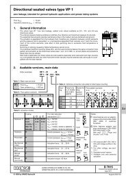
Model 70122Fault - LogicTroubleshootingSymptom: Pump Noisy or OverheatingCheckCheckOil Level in OK Hyd. Fluid OKReservoirSpecs1 2 3InspectInlet Screenor StrainerOKReplacePumpBelow LevelImproperCloggedFill toProperLevelInstallProperFluidCleanorReplaceDiagram Action Step Comments1. Check Oil Level in Reservoir:A. Fill to proper level.2. Check Hydraulic Fluid Specifications:A. Consult owner/operators manual for theproper type fluid.3. Inspect Inlet Screen or Strainer for:A. Suction screen or strainer plugged.B. Suction line to small or too longC. Suction line collapsed or plugged.194. Inspect Compensator Signal for:A. Improper size or length of signal line.B. Damaged or obstructed signal line5. *Inspect Pump Compensator for:A. Misadjusted pressure or flow setting.B. Pressure or flow spool stuck open.C. Pressure or flow spring weak or broken.*Standard factory compensator pressure settingsA. Pressure compensator set at 3000 to 3100 PSI(Optional settings of 1500 min. to 3100 max.PSI)B. Flow compensator set at 190 to 210 PSI(Optional settings of 190 min. to 450 max. PSI)
Model 70122Each order must include the following information.1. Product and/or Part Number2. Serial Number Code3. Part Name4. QuantityEaton CorporationHydraulics Division15151 Hwy. 5Eden Prairie, MN 55344Telephone 612/937-9800Fax 612/937-7130Eaton Ltd.Hydraulics DivisionGlenrothes, FifeScotland, KY7 4NWTelephone 01-592-771-771Fax 01-592-773-184Eaton GmbHHydraulics ProductsAm Schimmersfeld 740880 Ratingen, GermanyTelephone 02102-406-830Fax 02102-406-800ACCREDITED BYTHE DUTCH COUNCILFOR CERTIFICATIONReg. No. 24ISO-9001 CERTIFICATED FIRMDET NORSKE VERITAS INDUSTRY BV, THE NETHERLANDSQuality System CertifiedProducts in this catalog are manufacturedin an ISO-9001-certified site.Form No. 6-626July, 1991Copyright Eaton Corporation, 1991All Rights ReservedPrinted in USA20
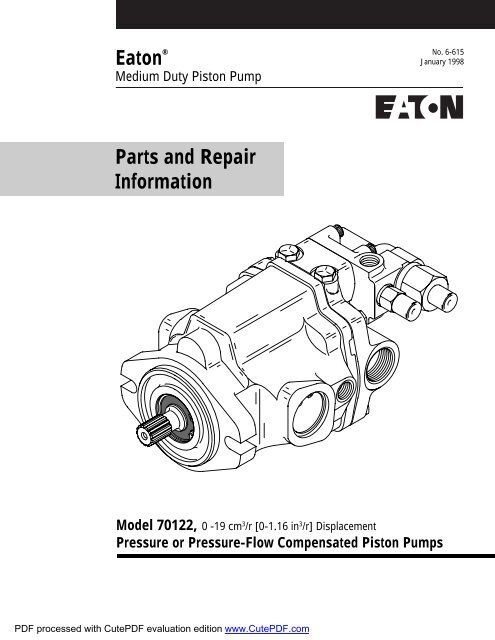
Eaton ®Medium Duty Piston PumpNo. 6-631January 1998Parts and RepairInformationModel 70422 or 704520 - 38 cm 3 /r [0 - 2.32 in 3 /r]DisplacementModel 70423 or 704530 - 45 cm 3 /r [0 - 2.77 in 3 /r]DisplacementPressure or Pressure-Flow Compensated Piston Pumps
Model 70422 or 70423IntroductionTable of ContentsIntroduction .........................................................................................................2Identification ........................................................................................................3Tools Required ....................................................................................................3Parts Drawing ......................................................................................................4Parts List .............................................................................................................5 - 15Item 1 - Drive Shaft ID ..................................................................................6item 2 - Backplate Assembly .........................................................................7 - 8Item 4 - Compensator Assembly and Parts List ............................................9 - 10Factory Pre-set Compensator Assemblies .....................................................11Item 3 - Housing Identification ......................................................................12Item 5 - Rotating Kit ......................................................................................12Mounting Kits ................................................................................................13Product Number ............................................................................................14 - 15Repair information ...............................................................................................16 - 18Disassembly ..................................................................................................16Inspection .....................................................................................................17Reassembly ...................................................................................................17 - 18Start-up Procedure ..............................................................................................19Fault - Logic Troubleshooting ..............................................................................20 - 23IntroductionThis manual provides service information for the Eaton Models 70422 or 70423 Pressure or Pressure - FlowCompensated Piston Pumps. Step by step instructions for the complete disassembly, inspection, andreassembly of the pump are given. The following recommendations should be followed to insure successfulrepairs.Remove the pump from the application.Cleanliness is extremely important.Clean the port areas thoroughly before disconnecting the hydraulic lines.Plug the pump ports and cover the open hydraulic lines immediately after they're disconnected.Drain the oil and clean the exterior of the pump before making repairs.Wash all metal parts in clean solvent.Use compressed air to dry the parts. Do not wipe them dry with paper towels or cloth.The compressed air should be filtered and moisture free.Always use new seals when reassembling hydraulic pumps.Lubricate the new rubber seals with a petroleum jelly (Vaseline) before installation.Torque all bolts over gasketed joints, then repeat the torquing sequence to make-up for gasketcompression.Verifying the accuracy of pump repairs on an authorized test stand is essential.2
Model 70422 or 70423Identification and Tools RequiredIdentification Numbers - Pressure or Pressure-Flow Compensated Piston PumpStamped on each units mounting flange.A - Product Number Description70422 = Single Piston Pump70452 = Single Piston Pump, w/ Aux. Flange70423 = Single Piston Pump70453 = Single Piston Pump, w/ Aux. FlangeB - RotationL - Left Hand (CCW)R - Right Hand (CW)C - Sequential NumberingRevision level of parts list.Serial Number Code:B 93 01 31 JBSingle Pump - Product Number:7 0 4 2 3 - R A AATesters InitialsBCLast two digits of year built.( 93 for 1993 etc.)Day of Month (two digits)Month (two digits)Year Manufactured(1 for 1991 etc.)Change CodeSerial Number Code prior to Jan., 1992:1 B- 52-JBTesters InitialsWeek of YearTools Required• 9/16 Inch Socket• 1-1/8 Inch End Wrench• 11/16 Inch End Wrench• Rachet Wrench• Torque Wrench (100 lb./ft.)• 3/16 Inch Hex Key (Allen)• 3/16 Inch Hex Key (Allen Socket)• Soft Face Hammer• Internal Retaining Pliers (Straight .070 Tip)• External Retaining Pliers (Straight .070 Tip)• Regular or Locking Pliers• Seal Driver or Similar Tool• Petroleum Jelly (Such as Vaseline)• 3/8 inch I.D. x 1-1/8 inch O.D. flat washer (2 ea.)• 3/8 inch x 3-1/4 inch N.C. Cap screw (1 ea.)• 3/8 inch N.C. Nut3
Model 70422 or 70423PartsDrawingPump drawn below is typical of a righthand (CW) rotation pump.269 625122121 22241582318 171314 33-2141238 15243-14 2710121120719 2816Serial code andassembly number location35(Cover only)52All left (CCW) or right (CW) directionsgiven are viewed from the input shaft end of the pump.4
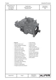
Model 70422 or 70423Parts ListItem Part No. Qty. Description1 ♦ 1 Drive Shaft (Identification drawing on page #6)2 ♦ 1 Backplate Assembly (Identification drawing on page #7 & 8)3 ♦ 1 Housing Assembly (Identification drawing on page #12)3-1 16238-11816 1 Bearing3-2 16026-808 2 Roll Pin4 ♦ 1 Compensator Assembly (Identification drawing on page #9, 10, & 11)5 ♦ 1 Rotating Kit Assembly (Parts list on page #12)6 70423-605 1 Camplate, 0 - 38 cm 3 /r [0 - 2.32 in 3 /r] Displacement6 70423-610 1 Camplate, 0 - 45 cm 3 /r [0 - 2.77 in 3 /r] Displacement7 70421-401 1 Control Piston, 0 - 38 cm 3 /r [0 - 2.32 in 3 /r] Displacement7 70423-418 1 Control Piston, 0 - 45 cm 3 /r [0 - 2.77 in 3 /r] Displacement+ 8 16015-27 2 O-ring, 2.38 mm Dia. x 36.51 mm ID. [.0937 in. Dia. x 1.4375 in. ID.]9 16026-608 1 Roll Pin10 16048-319 1 Washer+ 11 16077-32 1 Retaining Ring+ 12 16078-18 2 Retaining Ring13 17091-14 1 Spring14 70412-151 2 Thrust Bearing15 70412-607 2 Trunnion Cover+ 16 70412-626 1 Gasket17 70420-35 1 Pivot Button18 70420-59 1 Spring Collar+ 19 70422-600 1 Gasket+ 20 16253-18 1 Shaft Seal20 16253-218 1 Shaft Seal, Drive (fluorocarbon rubber)21 74308-100 2 Thrust Bearing Race22 74308-101 1 Thrust Bearing23 70402-100 2 Inner Race+ 24 16077-26 2 Retaining Ring+ 25 16003-405-90 1 O-ring, 1.59 mm Dia. x 6.35 mm ID. [.0625 in. Dia. x .25 in. ID.]26 16246-516 1 Key, Used on 19.05 [.75] diameter shaft26 24500-619 1 Key, Used on 22.2 [.875] diameter shaft27 16148-412 4 Cap Screw28 16032-612 4 Cap Screw32 170142-600 1 Cover Plate (In K3 kit)33 16032-610 2 Cap Screw, Cover Plate (In K3 kit)+ 34 16007-14 1 O-ring, (In K2 & K3 kit)35 70422-618 2 CoverMounting Kits (Drawings and parts list on Page #13)K2 70442-929 1 Gear Pump Mounting Kit (for "A" SAE flange)K3 70142-915 1 Cover Plate Kit, (for "A" SAE flange)K6 990596-000 1 Cover Plate Kit, (for "B" SAE flange)K7 70453-901 1 Gear Pump Mounting Kit, (for "B" SAE flange)Seal Repair Kit• 70422-915 1 Seal Repair KitLegend ♦ Refer to specific item parts list.+ Included in seal repair kits listed.5
Model 70422 or 70423Item 1 - Drive Shaft IdentificationItem 1Drive Shaft IdentificationPart Number Input Drive Output Drive70402-201, 13 Tooth70402-207, 15 Tooth70402-204,22.2 [.875] Dia. Keyed70442-235,25.4 [1.0] Dia. Keyed70452-200, 13 Tooth70442-228, 15 Tooth70442-225, 13 Tooth70442-246, 15 Tooth70442-231,22.2 [.875] Dia. KeyedUsed with 2-bolt A Flange backplateUsed with 2-bolt B Flange backplateUsed with 2-bolt A Flange backplateUsed with 2-bolt A Flange backplate9 ToothInternal41 ToothExternal9 ToothInternal9 ToothInternal70402-206, 13 Toothw/ Retaining Ring Groove6
Model 70422 or 70423Item 2 - Model 70422 Backplate Assembly(0 - 38 cm 3 /r [0 - 2.32 in 3 /r] Displacement)2-22-2-12(a)Rear Porting2(b)Opposite Side Porting2-3(Loctited)2-1Lefthand Rotation(CCW)Righthand Rotation(CW)2(c)Opposite Side Porting with 2-Bolt A Flange2-22-2-1Lefthand Rotation(CCW)Righthand Rotation(CW)2(d)Opposite Side Porting with 2-Bolt B FlangeLefthand Rotation(CCW)Righthand Rotation(CW)Lefthand Rotation(CCW)Righthand Rotation(CW)Item 2 - Model 70422 Parts List (0 - 38 cm 3 /r [0 - 2.32 in 3 /r] Displacement)Lefthand RighthandRotation RotationItem Part No. Part No. Qty. Description2(a) 70421-318 70421-343 1 Rear Porting Backplate Assembly2(b) 70421-327 70421-334 1 Opposite Side Porting Backplate Assembly2(c) 70452-302 70452-304 1 Auxiliary 2-Bolt A Flange Series 82-2, Opposite Side Porting Backplate2(d) --- 70452-317 1 Auxiliary 2-Bolt B Flange Series 101-2, Opposite Side Porting Backplate2-1 70421-150 1 Bearing2-2 16103-103 2 Plug Assembly+ 2-2-1 16133-3 2 O-ring, 1.59 mm Dia. x 7.54 mm I.D.[.0625 in. Dia. x .2969 in. I.D.]2-3 70422-428 1 Guide PinLegend + Included in seal repair kit listed on page 7.7All left (CCW) or right (CW) directionsgiven are viewed from the input shaft end of the pump.
Model 70422 or 70423Item 2 - Model 70423 Backplate Assembly(0 - 45 cm 3 /r [0 - 2.77 in 3 /r] Displacement)2-22-2-12(a)Rear Porting2(b)Opposite Side Porting2-3(Loctited)2-1Lefthand Rotation(CCW)Righthand Rotation(CW)2(c)Opposite Side Porting with 2-Bolt A Flange2-22-2-1Lefthand Rotation(CCW)Righthand Rotation(CW)2(d)Opposite Side Porting with 2-Bolt B FlangeLefthand Rotation(CCW)Righthand Rotation(CW)Lefthand Rotation(CCW)Righthand Rotation(CW)Item 2 - Model 70423 Parts List (0 - 45 cm 3 /r [0 - 2.77 in 3 /r] Displacement)Lefthand RighthandRotation RotationItem Part No. Part No. Qty. Description2(a) 70423-303 70423-301 1 Rear Porting Backplate Assembly2(b) 70423-306 70423-312 1 Opposite Side Porting Backplate Assembly2(c) 70453-301 70453-303 1 Auxiliary 2-Bolt A Flange Series 82-2, Opposite Side Porting Backplate2(d) --- 70453-307 1 Auxiliary 2-Bolt B Flange Series 101-2, Opposite Side Porting Backplate2-1 70421-150 1 Bearing2-2 16103-103 2 Plug Assembly+ 2-2-1 16133-3 2 O-ring, 1.59 mm Dia. x 7.54 mm I.D.[.0625 in. Dia. x .2969 in. I.D.]2-3 70422-428 1 Guide PinLegend + Included in seal repair kit listed on page 5.8All left (CCW) or right (CW) directionsgiven are viewed from the input shaft end of the pump.
Model 70422 or 70423Item 4 - Compensator AssemblyPressure-Flow CompensatorPressure Compensator*4-11Cover*4-11Cover*4-11Covernon-set non-set non-set4(a) 70422-HU 4(b) 70422-HY 4(c) 70422-HRLefthand (CCW) Pump Rotation Righthand (CW) Pump Rotation Fits Both Pump Rotations(Righthand (CW) rotation shown)*4-11, Cover not included with non-set compensator assy.4-194-19-14-74-84-94-104-114-24-34-14-124-44-144-164-134-154-54-694-174-184-94-104-11
Model 70422 or 70423Item 3 - Housing IdentificationItem 3Housing IdentificationItem Part No. Port Machined3 70402-304 A70402-310 C70402-336 B70402-371 A, B"A" Drain Port.5625-18 SAE Straight Thd."C" Drain Port"B" Drain Port.5625-18 SAE Straight Thd.55-55-65-95-75-7 5-85-25-35-45-1Item 5 - Rotating Kit AssemblyItem Part No. Qty. Description5 70402-638 1 Model 70422 Rotating Kit Assembly0 - 38 cm 3 /r [0 - 2.32 in 3 /r] Disp.5 70423-617 1 Model 70423 Rotating Kit Assembly0 - 45 cm 3 /r [0 - 2.77 in 3 /r] Disp.5-1 NSS 9 Piston Assembly5-2 NSS 1 Spider5-3 NSS 1 Spider Pivot5-4 NSS 1 Retainer5-5 NSS 1 Piston Block5-6 NSS 3 Pins5-7 NSS 2 Washer5-8 NSS 1 Spring5-9 NSS 1 Retaining Ring12NSS - Not Sold Separately
Model 70422 or 70423Mounting KitsKit 2, Gear Pump Mounting(To Mount "A" SAE flanges)Item Part No. Qty. DescriptionK2 70442-929 1 Gear Pump Mounting KitK2-1 16007-14 1 O-ring, 1.59 mm Dia. x 82.55 mm ID.[.0625 in. Dia. x 3.25 in. ID.]K2-2 16048-113 2 WasherK2-3 16032-612 2 Cap ScrewsK2-1K2-3K2-2Kit 7, Gear Pump Mounting(To Mount "B" SAE flanges)Item Part No. Qty. DescriptionK7 70423-901 1 Gear Pump Mounting KitK7-1 70423-615 1 Coupler, 41 ToothK7-2 16007-17 1 O-ring, 1.59 mm Dia. x 101.6 mm ID.[.0625 in. Dia. x 4 in. ID.]K7-3 16008-0 1 Lock RingK7-4 16032-814 2 Cap ScrewsK7-1K7-3K7-2K7-4Kit 3 & 6, Cover PlatesFor "A" SAE FlangesItem Part No. Qty. DescriptionK3 70142-915 1 Cover Plate Kit for "A" SAE flangeK3-1 16007-14 1 O-ring, 1.59 mm Dia. x 82.55 mm ID.[.0625 in. Dia. x 3.25 in. ID.]K3-2 70142-600 1 Cover PlateK3-3 16032-610 2 Cap ScrewsFor "B" SAE Flanges (Not Pictured)Item Part No. Qty. DescriptionK6 990596-000 1 Cover Plate Kit for "B" SAE flangeK6-1 102919-000 1 GasketK6-2 250073-000 1 Cover PlateK6-3 95865-100 2 Cap ScrewsK6-4 101896-050 2 Lock WasherK3-1K3-2K3-313
Model 70422 or 70423Product NumberThis list of product numbers is to aid in Item identification.If your product number is not listed contact your Eaton representitive.Model 70422, Lefthand Rotation (CCW)Description of Part NumberProduct Drive Shaft Backplate Assy. Housing Assy. Compensator Assy.Number Item #1 Item #2 Item #3 Item #470422-LAG 70402-206 70421-318 70402-304 70422-CA-0470422-LAH 70402-206 70421-318 70402-304 70422-AY-0370422-LAY 70402-204 70421-318 70402-304 70422-CA-0470422-LAZ 70402-204 70421-318 70402-304 70422-AY-0370422-LBJ 70402-206 70421-327 70402-304 70422-AY-0370422-LBK 70402-201 70421-327 70402-304 70422-CA-0470422-LBL 70402-204 70421-327 70402-304 70422-AY-0370422-LBM 70402-204 70421-327 70402-304 70422-CA-0470452-LAG 70442-225 70452-302 70402-304 70422-AY-0370452-LAJ 70442-225 70452-302 70402-304 70422-CA-0470452-LAK 70442-231 70452-302 70402-304 70422-AY-03Model 70422, Righthand Rotation (CW)Description of Part NumberProduct Drive Shaft Backplate Assy. Housing Assy. Compensator Assy.Number Item #1 Item #2 Item #3 Item #470422-RAT 70402-206 70421-343 70402-304 70422-CA-0470422-RAU 70402-206 70421-343 70402-304 70422-BM-0170422-RCB 70402-204 70421-343 70402-304 70422-CA-0470422-RCG 70402-204 70421-343 70402-304 70422-BM-0170422-RDM 70402-201 70421-334 70402-304 70422-BM-0170422-RDN 70402-206 70421-334 70402-304 70422-CA-0470422-RDQ 70402-204 70421-334 70402-304 70422-CA-0470452-RAG 70442-225 70452-304 70402-304 70422-BM-0170452-RAJ 70442-231 70452-304 70402-304 70422-CA-0470452-RAL 70442-231 70452-304 70402-304 70422-BM-0114All left (CCW) or right (CW) directionsgiven are viewed from the input shaft end of the pump.
Model 70422 or 70423Product NumberThis list of product numbers is to aid in Item identification.If your product number is not listed contact your Eaton representitive.Model 70423, Lefthand Rotation (CCW)Description of Part NumberProduct Drive Shaft Backplate Assy. Housing Assy. Compensator Assy.Number Item #1 Item #2 Item #3 Item #470423-LBA 70402-204 70423-303 70402-304 70422-AY-0370423-LBB 70402-201 70423-306 70402-304 70422-CA-0470423-LBD 70402-204 70423-306 70402-304 70422-CA-0470423-LBE 70402-204 70423-306 70402-304 70422-AY-0370423-LBF 70402-201 70423-303 70402-304 70422-CA-0470423-LBG 70402-201 70423-303 70402-304 70422-AY-0370453-LAF 70402-207 70453-301 70402-304 70422-AY-0370453-LAG 70402-207 70453-301 70402-304 70422-CA-04Model 70423, Righthand Rotation (CW)Description of Part NumberProduct Drive Shaft Backplate Assy. Housing Assy. Compensator Assy.Number Item #1 Item #2 Item #3 Item #470423-RBL 70402-204 70423-301 70402-304 70422-CA-0470423-RBM 70402-204 70423-301 70402-304 70422-BM-0170423-RBN 70402-201 70423-312 70402-304 70422-CA-0470423-RBQ 70402-204 70423-312 70402-304 70422-CA-0470423-RBS 70402-201 70423-301 70402-304 70422-CA-0470423-RBT 70402-201 70423-301 70402-304 70422-BM-0170453-RAG 70442-246 70453-303 70402-371 70422-BM-0170453-RAJ 70442-235 70453-303 70402-371 70422-CA-0415All left (CCW) or right (CW) directionsgiven are viewed from the input shaft end of the pump.
Model 70422 or 70423Repair InformationCleanliness is extremely important when repairingthese pumps. Work in a clean area. Beforedisconnecting the lines clean port area of pump.Disconnect hydraulic lines and remove pumpassembly from vehicle and plug ports. Thoroughlyclean the outside of pump. After cleaning, removeport plugs and drain oil.DisassemblyATTENTION: Removal of the adjusting screw coversfrom cap may void the warranty on this assembly.1 Clamp the end of the drive shaft in a protectedjaw vise with the body of the pump up and removethe four allen head screws (14) holding compensator(4).2 Remove the compensator assembly (4), 0-ring(28), and gasket (24).3 Remove the four cap screws (27) from thebackplate of the pump.4 Place a screw driver in slots provided betweenhousing and loosen backplate. Remove backplate (2)and gasket (21) from housing.5 Remove the control piston (7) remaining on thebackplate or in housing. Also remove plug (2-2) frombackplate (2).6 To remove rotating assembly (5) from housing,remove pump from vise and slide rotating assemblyoff shaft. Caution: pistons may not come out withpiston block.7 Remove pistons (5-1), spider (5-2), and spiderpivot (5-3) from piston block (5-5).8 The piston block assembly (5-5) need not bedisassembled unless the internal pins (5-6) or spring(5-8) are damaged.CAUTION: Use the following procedure if the springis to be removed from the piston block. The spring(5-8) is highly compressed and the snap ring (5-9)should not be removed without compressing thespring.The following parts will be needed to disassemble thepiston block:2 ea. 3/8 l.D. x 1-1/8 O.D. flat washer,1 ea. 3/8 x 3-1/4 N.C. cap screw, and1 ea. 3/8 N.C. nut.Place one of the flat washers over the 5/16 capscrew and place this through the center of the pistonblock. Place the other washer over the cap screw andlet it rest on the three pins. Screw the nut on andcompress the spring inside the piston block. Use apair of snap ring pliers and remove the internal snapring (5-9). Remove the nut and bolt along with thetwo washers (5-7), three pins (5-6), and the internalpin keeper (5-4).9 To free shaft seal and shaft, remove retainingring (12).10 Remove shaft (1) from housing (3) by tappingbackplate end of shaft with a wooden or plasticmallet.11 Remove shaft seal (17), washer (13), the tworetaining rings (10), the two thrust washers (16), andbearing (15) from shaft.12 To remove the camplate (6) from the housing,remove the two internal retaining rings (11) from thesides of the housing. Remove the two covers (20),the two o-rings (26), the two inner races (19), andthe bearings (25). The camplate can now be movedover to one side and removed. The two camplatepivot bearings are a loose slip fit into the housing. Donot be concerned if they are not tight.13 Remove the spring collar (22) and spring (18).Do not remove the button (23) and roll pin (9) unlessthey are worn or loose.14 The pressure-flow compensator assembly (4)may be disassembled for cleaning and inspection.16
Model 70422 or 70423Repair InformationATTENTION: Removal of the adjusting screw coversfrom cap may void the warranty on this assembly.15 Remove pressure adjustment cap (4-8) fromcompensator housing (4-1). Pressure spring follower(4-6) will remain in cap (4-8), pull follower from cap.16 Remove flow adjustment cap (4-18) fromcompensator housing (4-1). Flow spring follower (4-16) will remain in cap (4-18). Pull follower from cap.17 Remove springs (4-4 and 4-14) and spring pivots(4-3 and 4-13) from compensator housing.18 Remove plugs (4-19), pressure compensatorspool (4-2), and flow compensator spool (4-12) fromcompensator housing (4-1).19 The shaft seal, all 0-rings, and all gaskets shouldbe removed and replaced with new items uponreassembly.Inspect Parts For Wear1 Inspect the flat surface of the backplate (2), thefinish on the piston block side should be smooth andfree of grooves. The piston guide should be tight inthe backplate. The needle bearing in the backplateshould be free of excessive play and remain in thebearing cage. If the backplate has any of the wearcharacteristics outlined above, replace completebackplate assembly.2 Inspect the piston block (5). The surface thatcontacts the backplate should be smooth and free ofgrooves.3 The pistons (5-1) should move freely in thepiston block bore. If they stick in the bore, examinethe bore for scoring or contamination.4 Examine the O.D. of the piston (5-1) for finishcondition. They should not show wear or deepscratches. The shoes should be a snug fit on the ballend of the piston. The flat surface of the shoesshould be flat, and smooth. Do not lap piston shoes.5 Examine the spider (5-2). It should be flat, nocracks, and no signs of wear in the pivot area.6 Examine the pivot (5-3). It should be smooth andshow no signs of wear.7 Inspect the camplate (6) for the condition offinish of the polished shoe surface. It should showno signs of scoring.8 Inspect shaft (1) for wear in bearing and splineareas.9 Inspect thrust bearing (15) and thrust washers(16) for wear.10 Inspect the needle bearing in the housingassembly (3). If the needles are free of excessive playand remain in the bearing cage, there is no need toreplace the housing.11 Inspect the compensator springs (4-4 and 4-14)for breakage or weakness.12 Inspect the spools (4-2 and 4-12) for scoring.13 It is not necessary to inspect the o-rings,retaining rings, gaskets, or shaft seal as they shouldbe replaced as new items and are included in the sealrepair kit available for this assembly.Reassembly1 Clean all parts in suitable solvent; lubricate allcritical moving parts before reassembly.2 Install camplate control spring (18) and springcollar (22) in housing (3).3 Insert camplate (6) into housing (3). Insertneedle bearings (25) and bearing inner race (19) overthe camplate arms and slide into housing (3). Thenumbered end of the bearing should face outwardand the chamfered l.D. of the race should faceinward.4 Install new 0-ring (26) around O.D. of camplate17
Model 70422 or 70423Repair Informationpivot bearing (25). Install trunnion covers (20) andsecure with retaining rings (11).5 Install retaining ring (10) on shaft (1). Installthrust washer (16), thrust bearing (15), and secondthrust washer (16). Secure with second retaining ring(10).6 Install shaft (1) in housing (3) and install washer(13), shaft seal (17), and retain with retaining ring(12). Make sure retaining ring is seated in thegroove.7 If piston block assembly was disassembled,compress the pin keeper (5-4), and install in thespline area of piston block. Install the three pins (5-6) with the head end to the inside of the block andinstall in the special grooves of the piston blockspline.8 Install the washer (5-7), spring (5-8), and secondwasher (5-7) in the piston block. Use the two 3/8 l.D.washers and the 3/8 x 3-1/4 cap screw to compressthe spring and retain with retaining ring (5-9).Remove the 3/8 cap screw and the two washers.adjustment cap (4-18) with new o-ring (4-17) intocompensator housing (4-1). Torque plug (4-19) 8 to11 N-m [6 to 8 lb-ft] and torque flow adjustment cap(4-18) 14 to 16 N-m [10 to 12 lb-ft ].15 Place new 0-ring (4-19-1) on plug (4-19). Installplug assembly, pressure compensator spool (4-2),spring pivot (4-3), spring (4-4), pressure springfollower (4-6) with new o-ring (4-5), and pressureadjustment cap (4-8) with new o-ring (4-7) intocompensator housing (4-1). Torque plug (4-19) 8 to10 N-m [6 to 8 lb-ft] and torque pressure adjustmentcap (4-18) 47 to 54 N-m [35 to 40 lb-ft].16 Install new gasket (24) and new o-ring (28), theninstall compensator assembly (4),and retain withfour allen head cap screws (14) and torque to 14 to16 N-m [10 to 12 lb-ft].17 Plug ports to preserve cleanliness untilinstallation on vehicle. (Refer to start up procedures.)9 Install the pivot (5-3), spider (5-2), and pistonassemblies (5-1) in the piston block. Install thisassembly in the housing assembly, the piston shoesmust be in contact with the camplate. Be sure all theparts are in their proper position.10 Clamp this assembly in a protected jaw vise withthe open end of the housing (3) up.11 Install new gasket (21).12 Install control piston (7), and plug (2-2) with newo-ring onto backplate. Note roll pin (3-2) locations.13 Install backplate (2) and retain with cap screws(27). Torque to 37 to 42 N-m [27 to 31 lb-ft].14 Place new o-ring (4-19-1) on plug (4-19). Installplug assembly, flow compensator spool (4-12),spring pivot (4-13), spring (4-14), flow springfollower (4-16) with new o-ring (4-15), and flow18
Model 70422 or 70423Start - up ProcedureWhen initially starting a rebuilt load sensing system,it is extremely important that the start-up procedurebe followed. It prevents the chance of damaging thepump which might occur if the system was notproperly purged with oil before start-up.1 After the pump has been properly installed ontothe machine and all hydraulic connections have beenmade, check all fittings to make sure that they aretight.2 Fill the pump housing at least 1/2 full withsystem oil that has been filtered through a 10 micronfilter.3 Fill the reservoir with an approved oil that hasbeen filtered through a 10 micron filter. Leave thefiller cap loose as a means of air that is trapped in thesystem.4 Note on gasoline or L.P. engines: remove the coilwire and turn the engine over for 15 seconds. Dieselengines: shut off the fuel flow to the injectors andturn the engine over for 15 seconds. This procedureenables the pump to pick-up the oil before start-up.At this time disconnect the sensor line from thepump compensator and pull one of the valve spoolswhile the engine is being turned over. This allows oilto flow through the sensor line, thus, removing anyair in the sensor line. Reconnect the sensor line aftera steady flow of oil is coming from the line.5 Replace the coil wire or return the fuel flow to theinjectors and start the engine. Run at low idle speedfor one minute. The pump should immediately pickup oil and go into low pressure standby. If there is noindication of fill in 30 seconds, stop engine anddetermine the cause.6 After the pump has stabilized in low pressurestandby, operate the control valve and steering, if thesystem is equipped with one, to purge the system ofair and to fill the cylinders with oil. Continueoperating the system slowly with no load until itresponds fully.7 Check fluid level at the reservoir and refill ifnecessary to the proper level at the reservoir andrefill if necessary to the proper level with anapproved filtered oil.8 Check all line connections for leaks tighten ifnecessary.9 The machine is now ready to be put intooperation.10 Short hour filter changes are recommended forthe first two changes after placing the machine backinto operation. The first filter would be changed in 3-5 hours and the second at approximately 50 hours.Routine scheduled filter changes are recommendedfor maximum life of hydraulic system.19
Model 70422 or 70423Fault - LogicTroubleshootingThis fault - logic troubleshooting guide is adiagnostic aid in locating pump problems.Match the pump systems with the problemstatements and follow the action steps shown in thebox diagrams. This will give expedient aid incorrecting minor problems eliminating unnecessarymachine down time.Following the fault - logic diagrams are diagramaction comments of the action steps shown in thediagrams. Where applicable, the comment number ofthe statement appears in the action block of thediagrams.Recommended Gauge LocationsTest PortInlet Vacuum - LH. RotationSystem Pressure - RH. RotationTest PortSystem Pressure - LH. RotationInlet Vacuum - RH. RotationLoad Sensing PortTee in Line to CheckLoad Sensing PressureCommentNumberDecisionSolutionTest PortSystem Pressure - RH. RotationSystem Pressure - LH. RotationSymptom:1Inspect?DefectiveRepairorReplaceActionStepLoad Sensing PortTee in Line to CheckLoad Sensing PressureDrain PortTee in Line to CheckCase PressureModel 704220 - 38 cm 3 /r [0 - 2.32 in 3 /r] DisplacementDrain PortTee in Line to CheckCase PressureTee in Line to suction port for inletvacuum test. Suction port is theModel 70423largest port.0 - 45 cm 3 /r [0 - 2.77 in 3 /r] DisplacementGauges RecommendedInlet vacuum gauge: 2 bar to 1 bar [30 PSI to 30 inHg]System pressure gauge: 700 bar [10,000 PSI]Case pressure gauge: 0 to 25 bar [0 to 300 PSI]20
Model 70422 or 70423Fault - LogicTroubleshootingDiagram Action Step Comments1. Check Oil Level in Reservoir:A. Fill to proper level.2. Check Hydraulic Fluid Specifications:A. Consult owner/operators manual for the propertype fluid.3. Inspect Inlet Screen or Strainer for:A. Suction screen or strainer plugged.B. Suction line to small or too longC. Suction line collapsed or plugged.4. Inspect Compensator Signal for:A. Improper size or length of signal line.B. Damaged or obstructed signal line5. *Inspect Pump Compensator for:A. Misadjusted pressure or flow setting.B. Pressure or flow spool stuck open.C. Pressure or flow spring weak or broken.*Standard factory compensator pressure settingsA. Pressure compensator set at 3000 to 3100 PSI(Optional settings of 1500 min. to 3100 max. PSI)B. Flow compensator set at 190 to 210 PSI(Optional settings of 190 min. to 450 max. PSI)23
Model 70523PartsDrawingPump drawn below is typical of a righthand (CW) rotation pump.8612212719203172318Serial code andassembly number location20281192721123-112142511161513 164132624230353432 3310(Cover only)79293029225All left (CCW) or right (CW) directionsgiven are viewed from the input shaft end of the pump.4
Model 70523Parts ListItem Part No. Qty. Description1 ♦ 1 Drive Shaft (Identification drawing on page #6)2 ♦ 1 Backplate Assembly (Identification drawing on page #7)3 ♦ 1 Housing Assembly (Identification drawing on page #10)3-1 77010-9 1 Bearing4 ♦ 1 Compensator Assembly (Identification drawing on page #8 & 9)5 ♦ 1 Rotating Kit Assembly (Parts list on page #10)6 70523-605 1 Camplate7 70523-423 1 Control Piston8 16026-608 1 Roll Pin9 16028-604 2 Dowel Pin10 70523-618 2 Cover11 16048-329 1 Washer+ 12 16077-34 3 Retaining Ring+ 13 16078-22 2 Retaining Ring14 16147-412 4 Cap Screw15 16241-2233 1 Thrust Bearing16 16241-C2233 2 Thrust Bearing Race17 17091-12 1 Spring18 70420-35 1 Pivot Button19 70500-100 2 Inner Race20 70500-101 2 Thrust Bearing21 70500-600 2 Trunnion Cover+ 22 70500-604 1 Gasket23 70523-400 1 Spring Collar+ 24 70523-610 1 Gasket+ 25 16232-22 1 Shaft Seal25 16233-22 1 Shaft Seal, Drive (fluorocarbon rubber)+ 26 16003-408-90 1 O-ring, 2.38 mm Dia. x 9.525 mm ID. [.0937 in. Dia. x .375 in. ID.]+ 27 16004-3 2 O-ring, 3.175 mm Dia. x 47.625 mm ID. [.125 in. Dia. x 1.875 in. ID.]27 16004-403 2 O-ring, 3.175 mm Dia. x 47.625 mm ID. [.125 in. Dia. x 1.875 in. ID.] (fluorocarbon)28 16246-612 1 Key, Used on 31.75 [1.25] diameter shaft29 16032-734 4 Cap Screw30 16032-720 2 Cap Screw32 70400-646 1 Mount Adapter, SAE "A" to "B" flange33 16147-610 2 Cap Screw34 16007-14 1 O-ring, (In K2 & K3 kit)35 70411-617 1 Coupler, for 9 tooth spline35 70411-604 1 Coupler, for 13 tooth splineMounting Kits (Drawings and parts list on Page #11)K2 70442-929 1 Gear Pump Mounting KitK3 70142-915 1 Cover Plate Kit, (for "A" SAE flange)K6 990596-000 1 Cover Plate Kit, (for "B" SAE flange)Seal Repair Kit• 70523-900 1 Seal Repair KitLegend ♦ Refer to specific item parts list.+ Included in seal repair kits listed.5
Model 70523Item 1 - Drive Shaft IdentificationItem 1Drive Shaft IdentificationPart Number Input Drive Output Drive70502-200, 14 Tooth70502-202,31.8 [1.25] Dia. Keyed70552-200, 14 Tooth70552-203, 14 ToothUsed with 2-bolt A Flange backplateUsed with 2-bolt B Flange backplateUsed with 2-bolt A Flange backplate9 ToothExternal13 ToothExternal9 ToothExternal70552-209,31.8 [1.25] Dia. Keyed6
Model 70523Item 2 - Backplate Assembly2-2(Loctited)2(a)Top Mounted Compensator2(c)Top Mounted Compensatorw/ "A" SAE Aux. Flange2-1Lefthand Rotation(CCW)Righthand Rotation(CW)2(b) Rear Mounted CompensatorLefthand Rotation(CCW)Righthand Rotation(CW)Item 2 - Parts ListLefthand RighthandRotation RotationItem Part No. Part No. Qty. Description2(a) 70523-301 70523-305 1 Opposite Side Porting, Top Mounted Compensator Backplate Assembly2(b) ---- 70523-341 1 Opposite Side Porting, Rear Mounted Compensator Backplate Assembly2(c) 70553-305 70553-303 1 Auxiliary 2-Bolt A Flange Series 82-2, Opposite Side Porting Backplate2-1 16237-11816 1 Bearing2-2 70523-614 1 Guide Pin7All left (CCW) or right (CW) directionsgiven are viewed from the input shaft end of the pump.
Model 70523Item 4 - Compensator AssemblyPressure-Flow CompensatorPressure Compensator*4-11Cover*4-11Cover*4-11Covernon-set non-set non-set4(a) 70523-FW 4(b) 70523-FU 4(c) 70523-FTLefthand (CCW) Pump Rotation Righthand (CW) Pump Rotation For Both Pump Rotations*4-11, Cover not included with non-set compensator assy.4-94-104-114-84-34-74-24-14-22-14-224-34-54-64-174-44-134-144-154-164-124-204-214-114-184-198
Model 70523Item 4 - Compensator Parts ListItem 4 - Parts List (Refer to drawings)Item Part No. Qty. Description4(a) 70523-FW 1 Non-Set Pressure-Flow Compensator Assembly, Lefthand Rotation4(b) 70523-FU 1 Non-Set Pressure-Flow Compensator Assembly, Righthand Rotation4(c) 70523-FT 1 Non-Set Pressure Compensator Assembly4-1 N/S 1 Compensator Body4-2 N/S 1 Pressure Spool4-3 70523-501 2 Spring Pivot4-4 17122-8 1 Spring+ 4-5 16003-7-90 1 O-ring, 1.588 mm Dia. x 8.26 mm I.D. [.0625 in. Dia. x .375 in. I.D.]4-6 70500-628 1 Pressure Rod+ 4-7 16015-24 1 O-ring, 2.38 mm Dia. x 31.75 mm I.D. [.0937 in. Dia. x 1.25 in. I.D.]4-8 70500-627 1 Adjustment Cap, Pressure4-9 16138-624 1 Set Screw4-10 16024-6 1 Nut4-11* 70523-618* 1or2 Cover*4-12 N/S 1 Flow Spool4-13 70500-605 1 Spring Pivot4-14 17046-12 1 Spring4-15 70500-629 1 Spring Pivot+ 4-16 16003-1 1 O-ring, 1.59 mm Dia. x 3.175 mm I.D. [.0625 in. Dia. x .125 in. I.D.]4-17 70500-631 1 Pressure Rod+ 4-18 16133-6 1 O-ring, 1.98 mm Dia. x 11.89 mm I.D. [.078 in. Dia. x .468 in. I.D.]4-19 70500-630 1 Adjustment Cap, Flow4-20 16139-516 1 Set Screw4-21 16024-5 1 Nut4-22 16103-104 2 Plug Assembly+ 4-22-1 16133-4 2 O-ring, 1.83 mm Dia. x 8.92 mm I.D. [.072 in. Dia. x .351 in. I.D.]Legend + Included in seal repair kit listed on page 5.NSS Not Sold Separately* Covers are not included with Non-Set CompensatorPre-set Pressure-Flow Compensator AssembliesNon-Set Pre-setAssembly Assembly Pump Rotation Pressure Setting Flow Setting70523-FU 70523-DS-01 Righthand (CW) 176±3.5 bar [2550±50 lbf/in 2 ] 13.8±0.7 bar [200±10 lbf/in 2 ]70523-FU 70523-EL-01 Righthand (CW) 193±3.5 bar [2800±50 lbf/in 2 ] 19.3±0.7 bar [280±10 lbf/in 2 ]70523-FU 70523-EW-01 Righthand (CW) 155±3.5 bar [2250±50 lbf/in 2 ] 5.68±1.2 bar [82.5±17.5 lbf/in 2 ]70523-FU 70523-FA-01 Righthand (CW) 193±3.5 bar [2800±50 lbf/in 2 ] 13.8±0.7 bar [200±10 lbf/in 2 ]70523-FU 70523-FG-01 Righthand (CW) 210±3.5 bar [3050±50 lbf/in 2 ] 13.8±0.7 bar [200±10 lbf/in 2 ]70523-FU 70523-FL-01 Righthand (CW) 193±3.5 bar [2800±50 lbf/in 2 ] 15.8±0.7 bar [230±10 lbf/in 2 ]70523-FW 70523-FH-02 Lefthand (CCW) 210±3.5 bar [3050±50 lbf/in 2 ] 13.8±0.7 bar [200±10 lbf/in 2 ]70523-FW 70523-FM-02 Lefthand (CCW) 134±3.5 bar [1950±50 lbf/in 2 ] 21.7±0.7 bar [315±10 lbf/in 2 ]Pre-set Pressure Compensator AssemblyNon-Set Pre-setAssembly Assembly Pump Rotation Pressure Setting70523-FT 70523-FJ-03 Both 210±3.5 bar [3050±50 lbf/in 2 ]9
Model 70523Item 3 - Housing IdentificationItem 5 - Rotating Kit AssemblyItem 3Housing IdentificationItem Part No. Port Machined3 70500-303 B70500-311 A70500-332 A, B"B" Drain Port.875-14 SAE Straight Thd.Top of PumpRightside (CW)"A" Drain Port.875-14 SAE Straight Thd.Leftside (CCW)Item 5Rotating Kit AssemblyItem Part No. Qty. Description5 70502-606 1 Rotating Kit Assembly5-1 NSS 9 Piston Assembly5-2 NSS 1 Spider5-3 NSS 1 Spider Pivot5-4 NSS 1 Retainer5-5 NSS 1 Piston Block5-6 NSS 3 Pins5-7 NSS 1 Washer5-8 NSS 1 Spring5-9 NSS 1 Retaining RingNSS - Not Sold Separately5-255-45-35-55-65-7 5-8 5-95-110
Model 70523Mounting KitsK2-3Kit 2, Gear Pump Mounting(To Mount "A" SAE flanges)Item Part No. Qty. DescriptionK2-1K2-2K2 70442-929 1 Gear Pump Mounting KitK2-1 16007-14 1 O-ring, 1.59 mm Dia. x 82.55 mm ID. [.0625 in. Dia. x 3.25 in. ID.]K2-2 16048-113 2 WasherK2-3 16032-612 2 Cap ScrewsK3-3Kit 3 & 6, Cover PlatesFor "A" SAE FlangesItem Part No. Qty. DescriptionK3 70142-915 1 Cover Plate Kit for "A" SAE flangeK3-1 16007-14 1 O-ring, 1.59 mm Dia. x 82.55 mm ID. [.0625 in. Dia. x 3.25 in. ID.]K3-2 70142-600 1 Cover PlateK3-3 16032-610 2 Cap ScrewsFor "B" SAE Flanges (Not Pictured)Item Part No. Qty. DescriptionK6 990596-000 1 Cover Plate Kit for "B" SAE flangeK6-1 102919-000 1 GasketK6-2 250073-000 1 Cover PlateK6-3 95865-100 2 Cap ScrewsK6-4 101896-050 2 Lock Washer11K3-1K3-2
Model 70523Product NumberThis list of product numbers is to aid in Item identification.If your product number is not listed contact your Eaton representitive.Model 70523, Lefthand Rotation (CCW)Description of Part NumberProduct Drive Shaft Backplate Assy. Housing Assy. Compensator Assy.Number Item #1 Item #2 Item #3 Item #470523-LAA 70502-200 70523-301 70500-303 70523-FJ-0370523-LAB 70502-200 70523-301 70500-303 70523-FH-0270523-LBF 70502-202 70523-301 70500-303 70523-FH-0270523-LBG 70502-202 70523-301 70500-303 70523-FJ-0370553-LAB 70552-200 70553-305 70500-303 70523-FH-0270553-LAK 70552-209 70553-305 70500-303 70523-FH-0270553-LAR 70552-203 70553-305 70500-303 70523-FH-02Model 70523, Righthand Rotation (CW)Description of Part NumberProduct Drive Shaft Backplate Assy. Housing Assy. Compensator Assy.Number Item #1 Item #2 Item #3 Item #470523-RAA 70502-200 70523-305 70500-303 70523-FJ-0370523-RAB 70502-200 70523-305 70500-303 70523-FG-0170523-RBE 70502-202 70523-305 70500-303 70523-FJ-0370553-RAB 70552-200 70553-303 70500-303 70523-FG-0170553-RAK 70552-209 70553-303 70500-303 70523-FG-0112All left (CCW) or right (CW) directionsgiven are viewed from the input shaft end of the pump.
Model 70523Repair InformationCleanliness is extremely important when repairingthese pumps. Work in a clean area. Beforedisconnecting the lines clean port area of pump.Disconnect hydraulic lines and remove pumpassembly from vehicle and plug ports. Thoroughlyclean the outside of pump. After cleaning, removeport plugs and drain oil.DisassemblyATTENTION: Removal of the adjusting screw coversfrom cap may void the warranty on this assembly.1 Clamp the end of the drive shaft in a protectedjaw vise with the body of the pump up and removethe four allen head screws (14) holding compensator(4).2 Remove the compensator assembly (4), 0-ring(26), and gasket (24).3 Remove the six cap screws (29, four ea. and 30,two ea.) from the backplate of the pump.4 Use a soft mallet to loosen backplate. Removebackplate (2) and gasket (22) from housing.5 Remove the control piston (7) remaining on thebackplate or in housing.6 To remove rotating assembly (5) from housing,remove pump from vise and slide rotating assemblyoff shaft. Caution: pistons may not come out withpiston block.7 Remove pistons (5-1), spider (5-2), and spiderpivot (5-3) from piston block (5-5).8 The piston block assembly (5-5) need not bedisassembled unless the internal pins (5-6) or spring(5-8) are damaged.CAUTION: Use the following procedure if the springis to be removed from the piston block. The spring(5-8) is highly compressed and the snap ring (5-9)should not be removed without compressing thespring.The following parts will be needed to disassemble thepiston block:2 ea. 1/2 l.D. x 1-3/8 O.D. flat washer,1 ea. 5/8 x 1-3/4 flat washer, and1 ea. 1/2 x 4-1/2 in. N.C. cap screw1 ea. 1/2 N.C. nut.Place one of the flat washers over the 1/2 x 4-1/2in. cap screw and place this through the center of thepiston block. Place the 5/8 washer over the capscrew and let it rest on the three pins. Place the other1/2 in. flat washer on the cap screw and screw thenut on and compress the spring inside the pistonblock. Use a pair of snap ring pliers and remove theinternal snap ring (5-9). Remove the nut and boltalong with the two washers (5-7), three pins (5-6),and the internal pin keeper (5-4).9 To free shaft seal and shaft, remove retainingring (12).10 Remove shaft (1) from housing (3) by tappingbackplate end of shaft with a wooden or plasticmallet.11 Remove shaft seal (25), washer (11), the tworetaining rings (13), the two thrust washers (16), andbearing (15) from shaft.12 To remove the camplate (6) from the housing,remove the two internal retaining rings (12) from thesides of the housing. Remove the two covers (21),the two o-rings (27), the two inner races (19), andthe bearings (20). The camplate can now be movedover to one side and removed. The two camplatepivot bearings are a loose slip fit into the housing. Donot be concerned if they are not tight.13 Remove the spring collar (23) and spring (17).Do not remove the button (18) and roll pin (8) unlessthey are worn or loose.14 The pressure-flow compensator assembly (4)may be disassembled for cleaning and inspection.ATTENTION: Removal of the adjusting screw covers13
Model 70523Repair Informationfrom cap may void the warranty on this assembly.15 Remove pressure adjustment cap (4-8) fromcompensator housing (4-1). Pressure rod (4-6) willremain in cap (4-8), pull rod from cap.16 Remove flow adjustment cap (4-19) fromcompensator housing (4-1). Pressure rod (4-17) willremain in cap (4-19). Pull rod from cap.17 Remove springs (4-4 and 4-14) and spring pivots(4-3, 4-13 and 4-15) from compensator housing.18 Remove plugs (4-22), pressure compensatorspool (4-2), and flow compensator spool (4-12) fromcompensator housing (4-1).19 The shaft seal, all 0-rings, and all gaskets shouldbe removed and replaced with new items uponreassembly.Inspect Parts For Wear1 Inspect the flat surface of the backplate (2), thefinish on the piston block side should be smooth andfree of grooves. The piston guide should be tight inthe backplate. The needle bearing in the backplateshould be free of excessive play and remain in thebearing cage. If the backplate has any of the wearcharacteristics outlined above, replace completebackplate assembly.2 Inspect the piston block (5). The surface thatcontacts the backplate should be smooth and free ofgrooves.3 The pistons (5-1) should move freely in thepiston block bore. If they stick in the bore, examinethe bore for scoring or contamination.4 Examine the O.D. of the piston (5-1) for finishcondition. They should not show wear or deepscratches. The shoes should be a snug fit on the ballend of the piston. The flat surface of the shoesshould be flat, and smooth. Do not lap piston shoes.5 Examine the spider (5-2). It should be flat, nocracks, and no signs of wear in the pivot area.6 Examine the pivot (5-3). It should be smooth andshow no signs of wear.7 Inspect the camplate (6) for the condition offinish of the polished shoe surface. It should showno signs of scoring.8 Inspect shaft (1) for wear in bearing and splineareas.9 Inspect thrust bearing (15) and thrust washers(16) for wear.10 Inspect the needle bearing in the housingassembly (3). If the needles are free of excessive playand remain in the bearing cage, there is no need toreplace the housing.11 Inspect the compensator springs (4-4 and 4-14)for breakage or weakness.12 Inspect the spools (4-2 and 4-12) for scoring.13 It is not necessary to inspect the o-rings,retaining rings, gaskets, or shaft seal as they shouldbe replaced as new items and are included in the sealrepair kit available for this assembly.Reassembly1 Clean all parts in suitable solvent; lubricate allcritical moving parts before reassembly.2 Install camplate control spring (17) and springcollar (23) in housing (3).3 Insert camplate (6) into housing (3). Insertneedle bearings (20) and bearing inner race (19) overthe camplate arms and slide into housing (3). Thenumbered end of the bearing should face outwardand the chamfered l.D. of the race should faceinward.4 Install new 0-ring (27) around O.D. of camplate14
Model 70523Repair Informationpivot bearing (20). Install trunnion covers (21) andsecure with retaining rings (12).5 Install retaining ring (13) on shaft (1). Installthrust washer (16), thrust bearing (15), and secondthrust washer (16). Secure with second retaining ring(13).6 Install shaft (1) in housing (3) and install washer(11), shaft seal (25), and retain with retaining ring(12). Make sure retaining ring is seated in thegroove.7 If piston block assembly was disassembled,compress the pin keeper (5-4), and install in thespline area of piston block. Install the three pins (5-6) into the special grooves of the piston block spline.8 Install the washer (5-7), spring (5-8), into thepiston block. Use the three washers and the 1/2 x 4-1/2 in. cap screw to compress the spring and retainwith retaining ring (5-9). Remove the cap screw andthe three washers.8 to 11 N-m [6 to 8 lb-ft ] and torque flowadjustment cap (4-19) 14 to 16 N-m [10 to 12 lb-ft ].15 Place new o-ring (4-22-1) on plug (4-22). Installplug assembly, pressure compensator spool (4-2),spring pivot (4-3), spring (4-4), second spring pivot(4-3), pressure rod (4-6) with new o-ring (4-5), andpressure adjustment cap (4-8) with new o-ring (4-7)into compensator housing (4-1). Torque plug (4-22)8 to 10 N-m [6 to 8 lb-ft ] and torque pressureadjustment cap (4-8) 47 to 54 N-m [35 to 40 lb-ft] .16 Install new gasket (24) and new o-ring (26), theninstall compensator assembly (4),and retain withfour allen head cap screws (14) and torque to 14 to16 N-m [10 to 12 lb-ft].17 Plug ports to preserve cleanliness untilinstallation on vehicle. (Refer to start up procedures.)9 Install the pivot (5-3), spider (5-2), and pistonassemblies (5-1) in the piston block. Install thisassembly in the housing assembly, the piston shoesmust be in contact with the camplate. Be sure all theparts are in their proper position.10 Clamp this assembly in a protected jaw vise withthe open end of the housing (3) up.11 Install new gasket (22).12 Install control piston (7), and plug (2-2) with newo-ring onto backplate. Note roll pin (3-2) locations.13 Install backplate (2) and retain with cap screws(29 and 30). Torque to 47 to 54 N-m [35 to 40 lb-ft].14 Place new o-ring (4-22-1) on plug (4-22). Installplug assembly, flow compensator spool (4-12),spring pivot (4-13), spring (4-14), spring pivot (4-150, pressure rod (4-17) with new 0-ring (4-16), andflow adjustment cap (4-19) with new 0-ring (4-18)into compensator housing (4-1). Torque plug (4-22)15
Model 70523Start-up ProcedureWhen initially starting a rebuilt load sensing system,it is extremely important that the start-up procedurebe followed. It prevents the chance of damaging thepump which might occur if the system was notproperly purged with oil before start-up.1 After the pump has been properly installed ontothe machine and all hydraulic connections have beenmade, check all fittings to make sure that they aretight.2 Fill the pump housing at least 1/2 full withsystem oil that has been filtered through a 10 micronfilter.3 Fill the reservoir with an approved oil that hasbeen filtered through a 10 micron filter. Leave thefiller cap loose as a means of air that is trapped in thesystem.4 Note on gasoline or L.P. engines: remove the coilwire and turn the engine over for 15 seconds. Dieselengines: shut off the fuel flow to the injectors andturn the engine over for 15 seconds. This procedureenables the pump to pick-up the oil before start-up.At this time disconnect the sensor line from thepump compensator and pull one of the valve spoolswhile the engine is being turned over. This allows oilto flow through the sensor line, thus, removing anyair in the sensor line. Reconnect the sensor line aftera steady flow of oil is coming from the line.5 Replace the coil wire or return the fuel flow to theinjectors and start the engine. Run at low idle speedfor one minute. The pump should immediately pickup oil and go into low pressure standby. If there is noindication of fill in 30 seconds, stop engine anddetermine the cause.6 After the pump has stabilized in low pressurestandby, operate the control valve and steering, if thesystem is equipped with one, to purge the system ofair and to fill the cylinders with oil. Continueoperating the system slowly with no load until itresponds fully.7 Check fluid level at the reservoir and refill ifnecessary to the proper level at the reservoir andrefill if necessary to the proper level with anapproved filtered oil.8 Check all line connections for leaks tighten ifnecessary.9 The machine is now ready to be put intooperation.10 Short hour filter changes are recommended forthe first two changes after placing the machine backinto operation. The first filter would be changed in 3-5 hours and the second at approximately 50 hours.Routine scheduled filter changes are recommendedfor maximum life of hydraulic system.16
Model 70523Fault - LogicTroubleshootingThis fault - logic troubleshooting guide is adiagnostic aid in locating pump problems.Match the pump systems with the problemstatements and follow the action steps shown in thebox diagrams. This will give expedient aid incorrecting minor problems eliminating unnecessarymachine down time.Following the fault - logic diagrams are diagramaction comments of the action steps shown in thediagrams. Where applicable, the comment number ofthe statement appears in the action block of thediagrams.Recommended Gauge LocationsLoad Sensing PortTee in Line to CheckLoad Sensing PressureExplanatoryDiagramCommentNumberDecisionSolutionSymptom:1Inspect?DefectiveRepairorReplaceActionStepInstall an in lineTest Port for:System Pressureand Inlet VacuumDrain PortTee in Line to CheckCase PressureGauges RecommendedInlet vacuum gauge: 2 bar to 1 bar [30 PSI to 30 inHg]System pressure gauge: 700 bar [10,000 PSI]Case pressure gauge: 0 to 25 bar [0 to 300 PSI]17
Model 70523Fault - LogicTroubleshootingSymptom:System will not Develop Proper Pressure or FlowCheckCheckOil Level in OK Hyd. Fluid OKReservoirSpecs1 2 3InspectInlet Screenor StrainerOK4InspectCompensatorSignalBelow LevelImproperCloggedLowFill toProperLevelInstallProperFluidCleanorReplaceInspectSignalLineOKDefectiveRepairorReplaceReplacePumpOKInspectPumpCompensator5DefectiveRepairorReplace18
Model 70523Fault - LogicTroubleshootingSymptom: Pump Noisy or OverheatingCheckCheckOil Level in OK Hyd. Fluid OKReservoirSpecs1 2 3InspectInlet Screenor StrainerOKReplacePumpBelow LevelImproperCloggedFill toProperLevelInstallProperFluidCleanorReplaceDiagram Action Step Comments1. Check Oil Level in Reservoir:A. Fill to proper level.2. Check Hydraulic Fluid Specifications:A. Consult owner/operators manual for theproper type fluid.3. Inspect Inlet Screen or Strainer for:A. Suction screen or strainer plugged.B. Suction line to small or too longC. Suction line collapsed or plugged.194. Inspect Compensator Signal for:A. Improper size or length of signal line.B. Damaged or obstructed signal line5. *Inspect Pump Compensator for:A. Misadjusted pressure or flow setting.B. Pressure or flow spool stuck open.C. Pressure or flow spring weak or broken.*Standard factory compensator pressure settingsA. Pressure compensator set at 3000 to 3100 PSI(Optional settings of 1500 min. to 3100 max.PSI)B. Flow compensator set at 190 to 210 PSI(Optional settings of 190 min. to 450 max. PSI)