Proportional Directional Valves with Feedback Proportional ... - Vickers
Proportional Directional Valves with Feedback Proportional ... - Vickers
Proportional Directional Valves with Feedback Proportional ... - Vickers

Create successful ePaper yourself
Turn your PDF publications into a flip-book with our unique Google optimized e-Paper software.
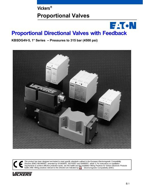
B.1<strong>Vickers</strong> ®<strong>Proportional</strong> <strong>Valves</strong><strong>Proportional</strong> <strong>Directional</strong> <strong>Valves</strong> <strong>with</strong> <strong>Feedback</strong>KBSDG4V-5, 1* Series – Pressures to 315 bar (4500 psi)This product has been designed and tested to meet specific standards outlined in the European Electromagnetic CompatibilityDirective (EMC) 89/336/EEC, amended by 91/263/EEC, 92/31/EEC and 93/68/EEC, article 5. For instructions on installationrequirements to achieve effective protection levels, see this leaflet and the Installation Wiring Practices for <strong>Vickers</strong> Electronic Productsleaflet 2468. Wiring practices relevant to this Directive are indicated by Electromagnetic Compatibility (EMC).
Spool DataTypical Section ViewKBSDG4V-5Spool SymbolsAvailable Spools for KBSDG4V-5A BP TSpool type 92LA BSpool Types and Flow RatingsSymmetric SpoolsBase line pressure drop (p) = 35 bar (500 psi) per metering flow path, e.g. B to T.For actual maximum flow refer to power capacity envelope curves.Spool code Spool symbol Flow ratingFor KBSDG4V-5 valves:92L2592L5092L8096L2596L5096L8092L92L92L96L96L96L25 L/min (6.5 USgpm)50 L/min (13 USgpm)80 L/min (21 USgpm)25 L/min (6.5 USgpm)50 L/min (13 USgpm)80 L/min (21 USgpm)P TSpool type 96LFunctional SymbolModel Type KBSDG4V-5proportional directional valve (<strong>with</strong> integral electronics)7-pinplugABPTL4
Operating dataData is typical <strong>with</strong> fluid at 36 cST (168 SUS) and 50C (122F)Power supplyCommand signalInput impedanceCommon mode voltage to pin BValve enable signal for model code PH7 & PR7EnableDisableInput impedance7–pin plug connectorAGFEElectromagnetic compatibility (EMC):Emission (10 V/m)Immunity (10 V/m)Zero adjustmentMonitor point signalOutput impedanceDBCView of pins of fixed half.24V DC (21V to 36V including 10% peak-to-peakmax. ripple) max current 3,7A0 to +10V DC, or 0 to –10V DC, or –10 V to +10 V DC47 kΩ18V (max)>8.5V (36V max)
Sub-plate Installation DimensionsSubplates <strong>with</strong> Rear Ports P, T, A, B, Maximum Pressure 210 bar (3000 psi)Model types: KDGSM-5-676805-2*(<strong>with</strong> rear port L)EKDGSM-01Y-1*-R(<strong>with</strong> side port L)P T B A LRear port L, KDGSM-5-676805 only:G 1 / 8 ( 1 / 8 BSPF) x 12,0 (0.47) full thread depth101,6 (4.0)C4 holes Ø 10,8 (0.42 dia) through,spotfaced Ø 17,5 (0.66 dia)11,5(0.45)LP T B A79,4 (3.12)12,7 (0.5)11,2 (0.44)114,3(4.5)WKFE68,3(2.7) 47,5(1.5)92,1(3.62)69,0(2.7)LATPB68,3(2.7)23,1(0.9)JHGMass = 1,3 kg (2.9 lbs)NSide port L,EKDGSM-01Y only:9 M/ 16 -18 UNF-2B x12,7 (0.5) full thread depth11,25,6(0.22)90,4(3.56)(0.44)4 holes tapped according to model type:For KDGSM-5 models (UNC port threads),1 / 4 -20 UNC-2B x 12,7 (0.5) deep.For EKDGSM-01Y models (BSPF port threads),M6 x 15,8 (0.62) deep.Model210 bar (3000 psi) KDGSM-5-676805-2280 bar (4000 psi) EKDGSM-01Y-10-RPorts P, T, A, B Threads3/4-16 UNF-2B x 14,0 (0.56) full thread depthG 1/2 (1/2” BSPF) x 15,0 90.59 full thread depthDimensionsModel210 bar (3000 psi )KDGSM-5-676805-2280 bar (4000 psi)EKDGSM-01Y-10-RC E F G H J K M N W45,2(1.78)42,1(1.66)19,0(0.75)68,3(2.69)45,2(1.78)23,8(0.94)42,1(1.66)31,8(1.25)23,8(0.94)57,1(2.25)39,7(1.56)40,5(1.59)9,9(0.39)70,6(2.78)39,7(1.56)10,7(0.42)40,5(1.59)36,5(1.44)28,6(1.13)72,6(2.86)9
Subplates <strong>with</strong> Rear Ports P, T, A, B, LMaximum Pressure 315 bar (4500 psiModel types: KDGSM-5-615225-1*KDGSM-5-615226-1*All dimensions in mm (inches)Recommended panel cut-out toclear fittings, Ø 108,0 (4.25 dia)89,0 (3.5)75,0 (3.0)APort L, G 1 / 4 ( 1 / 4 BSPF) x 12,0 (0.47),spotfaced to Ø 24,0 (0.94 dia)42,0(1.7)Port L, Ø 4,0 (0.16 dia)80,0 (3.15)13,0 (0.51)P T B AL4 holesØ 10,5 (0.41 dia)46,0(1.81)47,5(1.9)77,5(3.1)Z Y1,0(0.04)23,0(0.9)LATPB67,0(2.6)92,0(3.62)115,0(4.6)5,0 (0.2)Mass = 1,3 kg (2.9 lbs)40,0 (1.6)12,5 (0.5)17,0 (0.7)Ports P, T, A, B,Ø 10,5 (0.41 dia)88,0 (3.5)120,0 (4.8)4 holes M6 x14,0 (0.55) fullthread depthPorts P, T, A, BModel Y Thread Z diameterKDGSM-5-615225-10 G1/2 (1/2” BSPF) x 14,0 (0.55) full thread depth 30,0 (1.18)KDGSM-5-615226-10 G3/4 (3/4” BSPF) X 16,0 (0.63) full thread depth 33,0 (1.30)Electrical InformationBlock DiagramCommand Signals and Outputs7-pin plugPin DPositiveOVPin EOVNegativeU D - U E = PositiveNegativeOVOVPositiveU D - U E = NegativeFlowdirectionP to AP to B7-pin plug connectionsCommandsignalvoltage,see table+24V APower 0V BMonitor 0V CMonitor output FNon-inverting DInverting EProtective groundGWiringConnections must be made via the 7-pin plug mounted on the amplifier. Seepage 11 of this leaflet and Installation Wiring Practices for <strong>Vickers</strong> ElectronicProducts, leaflet 2468. Recommended cable sizes are shown below:Screen (shield):A suitable cable would have 7 cores, aseparate screen for the signal wiresand an overall screen.Cable outside diameter 8,0–10,5 mm(0.31–0.41 inches)See connection diagram on next page.Signal cables:0,50 mm 2 (20 AWG)Power cables:For 24V supply0,75 mm 2 (18 AWG) up to 20m (65 ft)1,00 mm 2 (16 AWG) up to 40m (130 ft)Valve envelopeNote:+15V0V–15V+24VGainLVDTCompensationnetworkOffset+24VSolenoiddriveModulatorIn valves <strong>with</strong> PH7 or PR7 type electricalconnection, pin C is used for a valveenable signal.WarningAll power must be switchedoff before connecting ordisconnecting any plugs.10
Typical Connection ArrangementsWiring ConnectionsUser PanelPowerSupply +24V0VOuter ScreenKB..PC7/PE7 valveABSpool position monitor voltage (pin F)will be referenced to the KB valve localground. A “local ground” (pin C) isprovided on PC7/PE7 versions foroptional use by differential input customersupplied electronics.DemandSignalSpoolPositionMonitorEnclosure0V+/-10V0VInput0V must beconnected to groundInner ScreenDrain WireC D or EValveG must beconnectedto groundF viasubplateConnectorshellWARNINGDo not ground pin C. If the localground (pin C) is not used for differentialmonitor electronics, do not use. Readmonitor pin F <strong>with</strong> respect to ground.Wiring Connections for <strong>Valves</strong> <strong>with</strong> Enable FeaturePowerSupplyEnableSignalDemandSignalSpoolPositionMonitorUser Panel+24V0V0V+8.5Vto 36V0V10V0VInputOuter ScreenInner ScreenDrain WireKB..PR7/PH7 valveABC D or EE or DGFNote:In applications where the valve mustconform to European RFI/EMCregulations, the outer screen (shield)must be connected to the outer shell ofthe 7 pin connector, and the valvebody must be fastened to the earthground. Proper earth groundingpractices must be observed in thiscase, as any differences in commandsource and valve ground potentials willresult in a screen (shield) ground loop.0V must beconnected to groundValve must beconnected toConnectorground viashellsubplateWarningElectromagnetic Compatibility (EMC)It is necessary to ensure that the valve is wired up as above. For effective protection the user electrical cabinet, the valve subplate ormanifold and the cable screens should be connected to efficient ground points. The metal 7 pin connector part no. 934939 should be used for theintegral amplifier.In all cases both valve and cable should be kept as far away as possible from any sources of electromagnetic radiation such as cables carryingheavy current, relays and certain kinds of portable radio transmitters, etc. Difficult environments could mean that extra screening may benecessary to avoid the interference.It is important to connect the 0V lines as shown above. The multi-core cable should have at least two screens to separate the demand signaland monitor output from the power lines.The enable line to pin C should be outside the screen which contains the demand signal cables.11
Application DataFluid CleanlinessProper fluid condition is essential forlong and satisfactory life of hydrauliccomponents and systems. Hydraulicfluid must have the correct balance ofcleanliness, materials and additives forprotection against wear of components,elevated viscosity and inclusion of air.Recommendations on contaminationcontrol methods and the selection ofproducts to control fluid condition areincluded in <strong>Vickers</strong> publication 9132 or561, “<strong>Vickers</strong> Guide to SystemicContamination Control”. The book alsoincludes information on the <strong>Vickers</strong>concept of “ProActive Maintenance”.The following recommendations arebased on ISO cleanliness levels at2 m, 5 m and 15 mFor products in this catalog therecommended levels are:0 to 70 bar (1000 psi) . . . . . . 18/16/1370 + bar (1000 + psi) . . . . . . . 17/15/12<strong>Vickers</strong> products, as any components, willoperate <strong>with</strong> apparent satisfaction influids <strong>with</strong> higher cleanliness codes thanthose described. Other manufacturers willoften recommend levels above thosespecified.Experience has shown, however, thatlife of any hydraulic components isshortened in fluids <strong>with</strong> highercleanliness codes than those listedabove. These codes have been provento provide a long trouble-free servicelife for the products shown, regardlessof the manufacturer.Hydraulic FluidsMaterials and seals used in these valvesare compatible <strong>with</strong> antiwear hydraulicoils, and non-alkyl-based phosphateesters. The extreme operating viscosityrange is 500 to 13 cSt (2270 to 70 SUS)but the recommended running range is 54to 13 cSt (245 to 70 SUS).InstallationThe proportional valves in this catalog canbe mounted in any attitude, but it may benecessary in certain demandingapplications, to ensure that the solenoidsare kept full of hydraulic fluid. Goodinstallation practice dictates that the tankport and any drain port are piped so as tokeep the valves full of fluid once thesystem start-up has been completed.Mounting Bolt KitsFor KBSDG4V-5BKDG01633M (metric)BKDPNG40706 (inch)If not using <strong>Vickers</strong> recommended boltkits, bolts used should be to ISO 898,12.9 or better.Seal KitsKBSDG4V-5 . . . . . . . . . . . . . 02-332751PlugsKBSDG4V7-pin plug (metal) . . . . . . . . . . . 9349397-pin plug (plastic) . . . . . . . . . . 694534(metal plug must be used for full EMCprotection)NOTE: An alternative metal connectorwhich gives EMC protection but notIP67 rating is available fromITT-Cannon, part numberCA06-COM-E-14S-A7-S. For IP ratingconsult the manufacturer.Extension CableExtension Cable: Adapter forextending 7 core cable when changingfrom KA to KB valve and existingwiring is not long enough. Consists ofa 7 pin plug, a 7 pin socket and alength of cable, fully assembled forease of useExtension Cable . . . . . . . . . . . . 944450Service InformationThe products from this range arepreset at the factory for optimumperformance; disassembling criticalitems would destroy these settings. Itis therefore recommended that shouldany mechanical or electronic repair benecessary they should be returned tothe nearest <strong>Vickers</strong> repair center. Theproducts will be refurbished asnecessary and retested tospecification before return.Field repair is restricted to thereplacement of the seals.Note: The feedback/solenoidassembly installed in this valve shouldnot be disassembled.<strong>Vickers</strong> Systems DivisionAeroquip-<strong>Vickers</strong> LtdP.O. Box 4New Lane, HavantHampshire PO9 2NBEnglandAeroquip-<strong>Vickers</strong> do Brazil S.A.CEP 07250-270Av. Julia Gaioli, 450Bonsucesso-GuarulhosSao Paulo 07Brazil<strong>Vickers</strong> Asia Pacific LtdTennozu Parkside Building2-5-8 Higashi ShinagawaShinagawa-kuTokyo 140Japan<strong>Vickers</strong>, Incorporated5445 Corporate DriveP.O. Box 302Troy, Michigan48007-0302USA5071.03/EN/1097/APrinted in U.S.A.