SERIES GRA PARALLEL GRIPPERS - Teknalia
SERIES GRA PARALLEL GRIPPERS - Teknalia
SERIES GRA PARALLEL GRIPPERS - Teknalia

Create successful ePaper yourself
Turn your PDF publications into a flip-book with our unique Google optimized e-Paper software.
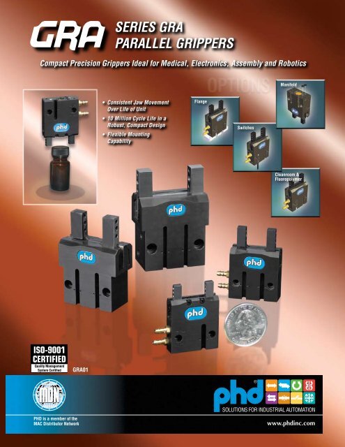
<strong>GRA</strong><strong>SERIES</strong> <strong>GRA</strong><strong>PARALLEL</strong> <strong>GRIPPERS</strong>Compact Precision Grippers Ideal for Medical, Electronics, Assembly and RoboticsPrecision Jaw Movement• Consistent Jaw High Movement Moments FlangeOver Life of UnitHighest Grip Force to Height Ratio• 10 Million Cycle Life in aRobust, Compact Design• Flexible MountingCapabilitySwitchesManifoldCleanroom &Fluoropolymer<strong>GRA</strong>01
ORDERING DATA: <strong>SERIES</strong> <strong>GRA</strong> <strong>PARALLEL</strong> <strong>GRIPPERS</strong>INDEX:Ordering DataPage 2BenefitsPage 3DimensionsPages 4 and 5Engineering DataPages 6 and 7Options &AccessoriesPages 8 to 11Exploded View &Parts ListPage 12<strong>GRA</strong> - 5TO ORDER SPECIFY:Product, Design No., Size, Minimum Total Jaw Travel,and any options required.DESIGN NO.5 - MetricOPTIONS (Omit if not required)MANIFOLD OPTIONL11-UB99 - Manifold option in location 99MOUNTING OPTIONGR9 - Mounting flange in location 99FLUID COMPATIBILITYV1 - Fluoro-Elastomer Seals and LubricantsLUBRICATIONY4 - Cleanroom Grade Lubricant- 6 x 4 - L11-UB99STANDARD PORTIN LOCATION 2699 OPTION:MANIFOLD INLOCATION 9926PRODUCTSmall Profile Precision Jaw PRODUCT BORE DIA.Movement Parallel Gripper SIZE mm inch6 6 .236NOTE: Design No. indicatesmetric mountings, dowel pinholes, and ports.101620101620.394.630.787MINIMUM TOTAL JAW TRAVELTotal Travel Per Bore Sizemm inch equivalent4 .1575 .1979 .35413 .512<strong>SERIES</strong> JC1SD MAGNETIC SWITCHESPART NO.SWITCH DESCRIPTIONJC1SDP-5 PNP (Source), Solid State, 10-30 VDC, 5 meter cableJC1SDP-K PNP (Source), Solid State, 10-30 VDC, Quick ConnectJC1SDN-5 NPN (Sink), Solid State, 10-30 VDC, 5 meter cableJC1SDN-K NPN (Sink), Solid State, 10-30 VDC, Quick ConnectIncludes one switch and installation directionsMINIMUM JAW TRAVEL = MINIMUM OPENPOSITION - MAXIMUM CLOSED POSITIONMINIMUM OPEN POSITIONMAXIMUMCLOSEDPOSITION<strong>SERIES</strong> JC1ST TWO POSITION TEACHABLE MAGNETIC SWITCHESPART NO.JC1STP-2JC1STP-KSWITCH DESCRIPTIONPNP (Source), Solid State, 12-30 VDC, 2 meter cablePNP (Source), Solid State, 12-30 VDC, Quick ConnectIncludes one switch and installation directions© Copyright 2010, by PHD, Inc. All Rights Reserved. Printed in the U.S.A.(800) 624-8511www.phdinc.com/gra<strong>GRA</strong>01
<strong>SERIES</strong> <strong>GRA</strong> <strong>PARALLEL</strong> <strong>GRIPPERS</strong>fully supported hardenedsteel jaws provide long lifewith minimal wear and highmoment capabilitysimple mounting of toolingwith two dowel pins and asingle screw per jawlow friction metallic cam driverprovides smooth movement andlong life without maintenanceangled cam drive provides highgrip forces throughout jaw traveluniversal port threads onsizes 16 & 20 or universalfittings installed on sizes 6 &10 simplify installationmanifold capable forincreased mounting flexibilityH7-tolerance dowel holessupplied in jaws and bodyfor accurate mountinghardcoated aluminum body withprecision machined jaw guidesdelivers robust, wear resistant jawsupport and rod guidanceintegrated switch slots requireno additional bracketrystandard mounting providesflexibility with back, bottom andfront through mounting. GR9option provides top throughmountinglarge cross-section sealsprovide long-life with low wearstandard unit includes magnetfor use with two-position teachableor single position switchesslim design allows “stacking” ofgrippers in a confined areaMajor Benefits• Series <strong>GRA</strong> Gripper’s compact, flexible design provides large momentcapacities and long tooling lengths.• Factory set jaw guide system minimizes jaw “free-play” and reduces jawdeflection when gripping or moving loads.• Robust construction ensures long operating life.• True parallel jaw motion simplifies jaw tooling and is ideal for centeringparts of various sizes.• H7-tolerance dowel pin holes included for accurate alignment of toolingand gripper mounting.• Double acting for use in both internal and external gripping applications.• Manifold porting capability allows for nested gripper installation.• Mounting provided from top (with option GR9), bottom, front, and backof gripper.• Internal speed control is standard, no external speed control required.• Standard with imperial / metric porting, metric mounting threads anddowel holes for global appeal.• Supplied “switch-ready” for easy integration of optional magneticposition sensing switches.• Magnetic sensing two-teachable position switch available to simplifyset-up and integration.• Standard four working day delivery reduces integration time.Industry/Process Uses• Medical device manufacture• Semiconductor manufacture• Laboratory processing applications• Clamping and fixturing during assembly operations• Centering and registration of parts• Incorporation into space restricted processing andmanufacturing equipmentConsistent Jaw Movement Over Life of Unit10 Million Cycle Life in a Robust,Compact DesignFlexible Mounting Capability<strong>GRA</strong>01(800) 624-8511www.phdinc.com/gra
DIMENSIONS: <strong>SERIES</strong> <strong>GRA</strong> <strong>PARALLEL</strong> <strong>GRIPPERS</strong>B12X K7 [H7]DOWEL PIN HOLESEE NOTE 6K10K11B3B42X K6 THDK8K9B22X K1 THD3K3MOUNTING THDS2X THRU HOLE FOR K12MOUNTING FASTENERSECTION2X K2 [H7]DOWEL PIN HOLESEE NOTE 64 21K145K5K4DOWEL HOLESP6P3B5P22X P1 PORTOPEN PORT(K16)P5P4K13K15 P7MAXIMUMFITTING J4(J8)J9 MIN6BARB FITTINGSSUPPLIED WITHSIZE 6 & 10. TUBEI.D. .125 [3 mm]CLOSE PORTJ3/22X J1 THDJ7A CLOSED(SEE NOTE 3)J64X J2 [H7]DOWEL PIN HOLESEE NOTE 6J5J3A OPEN(SEE NOTE 3)(800) 624-8511www.phdinc.com/gra<strong>GRA</strong>01
DIMENSIONS: <strong>SERIES</strong> <strong>GRA</strong> <strong>PARALLEL</strong> <strong>GRIPPERS</strong>LETTERDIMNOMINAL TOTALJAW TRAVELA CLOSEDA OPENB1B2B3B4B5J1J2J3J4J5J6J7J8J9 MINK1K2K3K4K5K6K7K8K9K10K11K12K13K14K15K16P1P2P3P4P5P6P7<strong>GRA</strong>-5-6x4in mm.157.9851.1421.220N/AN/A1.355.394.19691.535.118.197.1771.713.172.945.6890.177.5120.945.827.295.289.9451.112.4134.025.029.031.0N/AN/A34.410.0M1.6 x 0.351.55.0039.03.05.04.543.54.4M2.5 x 0.45 x 5 DP2.0 x 3.0 DP24.017.504.5M3 x 0.5 x 6 DP2.0 x 3.0 DPM2.513.0024.021.07.57.324.028.2510.5M3 x 0.5 x 3 DP.059 1.5.039 1.0.256 6.5.610 15.5.990 25.1.256 6.5MODEL NUMBER<strong>GRA</strong>-5-10x5 <strong>GRA</strong>-5-16x9 <strong>GRA</strong>-5-20x13in mmin mmin mm.1981.0631.2611.339N/AN/A1.518.630.27561.850.177.236.2362.087.215.984.9843.394.55121.0631.024.315.5071.0631.339.5125.027.032.034.0N/AN/A38.616.0M2.5 x 0.452.07.0047.04.56.06.053.05.5M3 x 0.5 x 6.5 DP2.0 x 3.0 DP25.025.0010.0M3 x 0.5 x 6.5 DP2.0 x 3.0 DPM2.514.0027.026.08.012.927.034.013.0M3 x 0.5 x 3 DP.118 3.0.019 .5.236 6.0.709 18.01.050 26.7.374 9.5.3531.3391.6921.7721.4961.01911.784.866.39372.224.276.354.3152.540.2881.2601.2598.591.78741.1811.378.315.7081.1811.693.531M4 x 0.72.59.034.043.045.038.025.945.322.010.0056.57.09.08.064.57.3M3 x 0.5 x 6.5 DP3.0 x 4.0 DP32.032.0015.0M4 x 0.7 x 8 DP3.0 x 4.0 DPM320.0030.035.08.018.030.043.013.5M5 x 0.8 x 4.5 DP.158 4.0.138 3.5.295 7.5.750 19.1N/A N/A.512 13.0.5111.4181.9292.0081.8111.2212.1101.102.47242.618.335.394.3542.972.3591.4171.4173.748.86611.4171.595.354.9251.4171.949.669M5 x 0.83.013.036.049.051.046.031.053.628.012.0066.58.510.09.075.59.1M4 x 0.7 x 8 DP4.0 x 4.0 DP36.036.0019.0M5 x 0.8 x 10 DP4.0 x 4.0 DPM422.0036.040.59.023.536.049.517.0M5 x 0.8 x 4.5 DP.197 5.0.158 4.0.354 9.0.945 24.0N/A N/A.512 13.0NOTES:1) ALL DIMENSIONS ARE REFERENCE ONLY UNLESS SPECIFICALLY TOLERANCED2) METRIC INFORMATION SHOWN IN [ ] DESIGNATED mm3) A OPEN REFLECTS SMALLEST POSSIBLE OPEN DIMENSION (+.052/-.000 [+1.3 mm/-.0 mm])A CLOSED REFLECTS LARGEST POSSIBLE CLOSED DIMENSION (+.000/-.024 [+.0 mm/-.6 mm])4) CIRCLED NUMBERS INDICATE POSITIONS5) DESIGNATED C L IS CENTERLINE OF UNIT6) DOWEL PINS OR SPRING PINS OF THE SAME DIAMETER ARE RECOMMENDED. THIS PROVIDES A SMALL PRESS TO SLIGHTSLIP FIT DURING ASSEMBLY. PHD RECOMMENDS THE USE OF ANTI-SEIZE COMPOUNDS DURING ASSEMBLY.<strong>GRA</strong>01(800) 624-8511www.phdinc.com/gra
ENGINEERING DATA: <strong>SERIES</strong> <strong>GRA</strong> <strong>PARALLEL</strong> <strong>GRIPPERS</strong><strong>SERIES</strong> <strong>GRA</strong>SPECIFICATIONS IMPERIAL METRICOPERATING AIR PRESSURE 30 psi min. to 120 psi max. air 2 bar min. to 8.3 bar max. airOPERATING TEMPERATURE -20F min. to +180F max. -28C min. to +82C max.GRIP REPEATABILITY .0004 inch of original position .01 mm of original positionRATED LIFE10 million cyclesLUBRICATIONFactory lubricated for rated lifeSIZE6101620MINIMUMTOTALJAW TRAVELin mm.158 4.0.197 5.0.354 9.0.512 13.0TOTAL CLOSEGRIP FORCEAT 87 psi [6 bar]lb N2.55 118.2 3718.2 8127.7 123GRIPPERWEIGHTlb0.080.1630.360.62kg0.0360.0740.160.28DISPLACEMENTin 3 cm 30.005 0.080.016 0.260.063 1.030.134 2.20CLOSE OROPEN TIMEAT 87 psi [6 bar]sec.030.030.040.105MAXIMUMTOOLINGLENGTHin1.181.773.153.94mm304580100GRIP FORCE FACTORINTERNALGRIPEXTERNALGRIPIMP0.0240.0800.1670.254MET1.55.210.816.4IMP0.0290.0940.2090.318MET1.896.1013.520.5SIZE6101620AXIAL FORCEFalb3.25122540N1453111178MAXIMUM INDIVIDUAL MOMENTSMx My MzNm0.401.12.85.1in-lb1.705.02545Nm0.190.562.85.1in-lb1.705.02030in-lb3.5010.02545Nm0.190.562.33.4REFERENCEPLANEFa: Total for both jawsMx: Maximum allowable moment per jaw, relative to the referenceplaneMy: Maximum allowable moment per jaw, relative to the geometriccenter of the jaw fingerMz: Maximum allowable moment per jaw, relative to the referenceplaneWhen calculating the value for Fa, include the tooling weight,part weight, external forces, and accelerations. When calculatingvalues for Mx, My, and Mz, include the grip force per jaw, toolingweight, part weight, external forces, and accelerations as applicable.MzMxFaMxRECOMMENDATIONSDesign tooling so that the grip point is as close to the grippersurfaces as possible. The grip force factor (Gf) values given inthe table on page 6 are for zero tooling length. As the grip point ismoved away from the jaw surface, the applied moment causes jawfriction to increase, resulting in reduced effective grip force. Usethe tooling length factor chart on the following page to calculate theeffective grip force for a specific grip point.The maximum load that grippers can handle will vary basedon: size of the part being picked up, shape of the part, texture of thepart, speed at which the part is transferred, working pressure, shapeof the fingers, etc.MyMy(800) 624-8511www.phdinc.com/gra<strong>GRA</strong>01
ENGINEERING DATA: <strong>SERIES</strong> <strong>GRA</strong> <strong>PARALLEL</strong> <strong>GRIPPERS</strong>TOOLING LENGTH FACTORAs the grip point is moved away from the jaw surface, the gripforce is reduced due to additional friction generated by the gripinduced moment. The tooling length factor allows calculation of thegrip force at any grip point. The graph also indicates the maximumtooling length for each gripper size.<strong>GRA</strong> 6TOOLING LENGTH FACTOR1.000.990.980.970.960.950.94Max. Tooling Length0.930.920.910.900.0 0.20 0.40 0.60 0.80 1.00 1.20[5.08] [10.16] [15.24] [20.32] [25.4] [30.48]1.00<strong>GRA</strong> 16@100 psiTOOLING LENGTH in [mm]@87 psi@60 psiTOOLING LENGTH FACTOR1.000.950.900.850.800.751.00<strong>GRA</strong> 100.700.0 0.25 0.5 0.75 1.0 1.25 1.5 1.75 2.0[6.35] [12.7] [19.05] [25.4] [31.75] [38.1] [44.45] [50.8]TOOLING LENGTH in [mm]@100 psi<strong>GRA</strong> 20@87 psiMax. Tooling Length@60 psiTOOLING LENGTH FACTOR0.950.900.850.80Max. Tooling Length0.750.700.650.600.550.500.0 0.5 1.0 1.5 2.0 2.5 3.0 3.5[12.7] [25.4] [38.1] [50.8] [63.5] [76.2] [88.9]TOOLING LENGTH in [mm]GRIP force CALCULATION Equations:IMPERIAL:Total Grip Force [lb] = (Pressure [psi] x Gf) x Tooling Length Factor@100 psi@87 psi@60 psiTOOLING LENGTH FACTOR0.950.900.850.800.75Max. Tooling Length0.700.650.600.550.500.0 0.5 1.0 1.5 2.0 2.5 3.0 3.5 4.0[12.7] [25.4] [38.1] [50.8] [63.5] [76.2] [88.9] [101.6]TOOLING LENGTH in [mm]METRIC:Total Grip Force [N] = (Pressure [bar] x Gf) x Tooling Length Factor@100 psi@87 psi@60 psiGRIP FORCETotal gripping force relative to tooling length is shown below at 87 psi [6 bar]pressure. Grip force per jaw equals the total grip force divided by two. The graphs alsoindicate the maximum tooling length for each gripper size.<strong>GRA</strong> 6 & 10Grip Force at 87 psi [6 bar]TOTAL GRIP FORCE lb [N]9.00[40.0]8.00[35.6]7.00[31.1]6.00[26.7]5.00[22.2]4.00[17.8]3.00[13.3]2.00[8.90]1.00[4.45]0.000.00 0.25 0.50 0.75 1.00 1.25 1.50[6.35] [12.7] [19.05] [25.4] [31.75] [38.1]TOOLING LENGTH in [mm]TOTAL GRIP FORCE lb [N]30.0[133.4]25.0[111.2]20.0[89.0]15.0[66.7]10.0[44.5]5.0[22.2]<strong>GRA</strong> 6 & 16 Close<strong>GRA</strong> 6 & 16 Open<strong>GRA</strong> 16 & 20Grip Force at 87 psi [6 bar]<strong>GRA</strong> 10 & 20 Close<strong>GRA</strong> 10 & 20 Open0.00.00 0.50 1.00 1.50 2.00 2.50 3.00[12.7] [25.4] [38.1] [50.8] [63.5] [76.2]TOOLING LENGTH in [mm]<strong>GRA</strong>01(800) 624-8511www.phdinc.com/gra
OPTIONS: <strong>SERIES</strong> <strong>GRA</strong> <strong>PARALLEL</strong> <strong>GRIPPERS</strong>L11-UB99MANIFOLD PORTSWITH GR9 OPTIONWith this option the gripper is configured for manifoldmounting on the indicated mounting face. The standard portsare plugged. O-ring seals are provided for mounting between thegripper and the manifold.The manifold port option is also available in kit form. See theManifold Conversion Kits chart below.63F1B13OPEN PORT<strong>SERIES</strong> <strong>GRA</strong>GRIPPER OR FLANGEP12CUSTOMERMOUNTINGSURFACEB5P104 2 P13 P11P9O-RING P4OPTIONALFLANGEMOUNTING15P8CLOSE PORTMANIFOLD PORTING DIMENSIONSFor customer use (dimensions requiredon customer mounting surface)2X PORT PLUGS6REPLACEMENTMANIFOLD SEAL KITSSIZE6101620KIT NUMBER82013820138201382013Manifold kit includes sealsMANIFOLDCONVERSION KITSSIZE6101620KIT NUMBER82014-06-582014-10-582014-16-582014-20-5Manifold kit includes seals,port plugs, and installationdirectionsLETTERDIMP8P9P10P11P12P13P4 O-RING*(F1)(B1)(B5)<strong>GRA</strong>-5-6x4in.226.099.099.047.030.158mm5.752.52.51.2.84.02 mm x 1 mm1.653 42.01.220 31.0.394 10.0MODEL NUMBER<strong>GRA</strong>-5-10x5 <strong>GRA</strong>-5-16x9in.345.020.177.047.030.158mm7.75.54.51.2.84.0in.453.118.118.047.030.158mm11.53.03.01.2.84.02 mm x 1 mm 2 mm x 1 mm1.8501.339.63047.034.016.02.0471.772.86652.045.022.0NOTES:1) ALL DIMENSIONS ARE REFERENCE ONLY UNLESS SPECIFICALLY TOLERANCED2) CIRCLED NUMBERS INDICATE POSITIONS3) *I.D. x CROSS-SECTION<strong>GRA</strong>-5-20x13in mm.551 14.0.138 3.5.138 3.5.047 1.2.030 .8.158 4.02 mm x 1 mm2.4992.0081.10263.551.028.0(800) 624-8511www.phdinc.com/gra<strong>GRA</strong>01
OPTIONS: <strong>SERIES</strong> <strong>GRA</strong> <strong>PARALLEL</strong> <strong>GRIPPERS</strong>GR9BOTTOM MOUNTING FLANGEThe GR9 option adds a flange with thru holes to the bottom ofthe gripper allowing for top mounting. Dowel pin holes in the flangeare clearance to allow dowel pins to install in the body for accuratemounting. See chart for recommended dowel pin lengths.The GR9 option is sealed between the body and the flange toallow use of the L11-UB99 manifold option.The GR9 flange is also available in kit form. See FlangeMounting Kit chart below.F1F4F242X F8 [H7]DOWEL PIN HOLE(HOLES IN FLANGEARE CLEARANCE)F73152OPEN PORTF52X THRU HOLE FOR F6MOUNTING FASTENERCLOSE PORTFLANGE MOUNTING KITSIZE6101620KIT NUMBER81867-06-581867-10-581867-16-581867-20-5Kit includes: Flange,manifold seals, assemblyfasteners, and installationdirectionsF3F9 DOWEL PINHOLE DEPTH(HOLES IN FLANGEARE CLEARANCE)6LETTERDIMF1F2F3F4F5F6F7F8F9<strong>GRA</strong>-5-6x4in mm1.653 42.0.394 10.0.197 5.01.457 37.0.177 4.5M2.5.6890 17.52.0 mm x 3.0 mm DP.315 8.0MODEL NUMBER<strong>GRA</strong>-5-10x5 <strong>GRA</strong>-5-16x9in1.850.630.1971.614.394mm47.016.05.041.010.0in2.047.866.2361.772.591mm52.022.06.045.015.0M3M3.9843 25.0 1.2598 32.02.0 mm x 3.0 mm DP 3.0 mm x 4.0 mm DP.315 8.0 .394 10.0NOTES:1) ALL DIMENSIONS ARE REFERENCE ONLY UNLESS SPECIFICALLY TOLERANCED2) METRIC INFORMATION SHOWN IN [ ] DESIGNATED mm3) GR9 OPTION INCLUDES SEALS BETWEEN BODY AND FLANGE<strong>GRA</strong>-5-20x13in mm2.499 63.51.102 28.0.236 6.02.165 55.0.748 19.0M41.4173 36.04.0 mm x 4.0 mm DP.394 10.0V1FLUORO-ELASTOMERSEALS & LUBRICANTSY4CLEANROOM <strong>GRA</strong>DELUBRICANTFluoro-elastomer seals and lubricants are available to achieveseal compatibility with certain fluids. Seal compatibility should bechecked with the fluid manufacturer for proper application.Cleanroom grade lubricant replaces all standard lubricants.<strong>GRA</strong>01(800) 624-8511www.phdinc.com/gra
ACCESSORIES: <strong>SERIES</strong> <strong>GRA</strong> <strong>GRIPPERS</strong><strong>SERIES</strong> JC1ST TWO POSITIONTEACHABLE MAGNETIC SWITCHThis switch provides the ability to identify two separatelyprogrammable jaw positions with a single switch. Programmablecapability means no “fine-tuning.” With switch properly aligned,just place jaws in desired position and program. Solid-state sensingtechnology provides a highly reliable switch. Elliptical housing allowsfor easy “drop-in” installation on sizes 16 and 20 only. Includes LEDindicators for convenient means of positioning and programming.Available with cable or 8 mm threaded Quick Connect.<strong>SERIES</strong> JC1ST TWO POSITION TEACHABLE MAGNETIC SWITCHESPART NO.JC1STP-2JC1STP-KSWITCH DESCRIPTIONPNP (Source), Solid State, 12-30 VDC, 2 meter cablePNP (Source), Solid State, 12-30 VDC, Quick ConnectIncludes one switch and installation directionsPART NO.81284-1-001MATCHING CORDSETDESCRIPTIONM8, 4 pin, Straight Female Connector, 5 meter cableON SIZE 6, SWITCHSLOT IS AVAILABLE ONTHIS SIDE ONLY34 2SW1ALIGN SYMBOL ONSWITCH AND BODYFOR OPTIMUMPERFORMANCE SW3 MIN(FOR CLEARANCE)SW21ONE SWITCH FOR 2POSITION SENSING(SIZE 6 ALLOWSONE SWITCH ONLY)5INSTALLATION WRENCHHEX WRENCH SUPPLIEDWITH SENSORSW46SIZE 6 AND 10 SWITCHES AREINSTALLED AT AN ANGLE ASSHOWN. OFFSET SWITCH SLOTSCONTROL THE ROTATION.SWITCHES SLIDE IN FROM END.LETTERDIMSW1SW2SW3SW4MODEL NUMBER<strong>GRA</strong>-5-6x4 <strong>GRA</strong>-5-10x5 <strong>GRA</strong>-5-16x9 <strong>GRA</strong>-5-20x13in mm in mm in mm in mm.100 2.5 .270 6.9 .358 9.1 .475 12.1.230 5.8 .213 5.4 .305 7.7 .315 8.0.169 4.3 .169 4.3 .169 4.3 .169 4.3.135 3.4 .070 1.8 NOTE: ALL DIMENSIONS ARE REFERENCE ONLY UNLESS SPECIFICALLY TOLERANCED10(800) 624-8511www.phdinc.com/gra<strong>GRA</strong>01
ACCESSORIES: <strong>SERIES</strong> <strong>GRA</strong> <strong>GRIPPERS</strong><strong>SERIES</strong> JC1SD MAGNETIC SWITCHThis switch provides the ability to identify a single jaw position.Solid-state sensing technology provides a highly reliable switch.Elliptical housing allows for easy “drop-in” installation. IncludesLED indicator for convenient means of positioning. Available withPNP or NPN output. Available with cable or 8 mm threaded QuickConnect.NOTE: Series JC1SD Switches only function on 16 and 20 mmunits. Series 6790 Reed Switches are not applicable.<strong>SERIES</strong> JC1SD MAGNETIC SWITCHESPART NO.SWITCH DESCRIPTIONJC1SDP-5 PNP (Source), Solid State, 10-30 VDC, 5 meter cableJC1SDP-K PNP (Source), Solid State, 10-30 VDC, Quick ConnectJC1SDN-5 NPN (Sink), Solid State, 10-30 VDC, 5 meter cableJC1SDN-K NPN (Sink), Solid State, 10-30 VDC, Quick ConnectIncludes one switch and installation directionsPART NO.63549-0263549-05MATCHING CORDSETDESCRIPTIONM8, 3 pin, Straight Female Connector, 2 meter cableM8, 3 pin, Straight Female Connector, 5 meter cable34 2HS1HS215 HS3 MIN(FOR CLEARANCE)HS4OPEN POSITIONSWITCHCLOSEDPOSITIONSWITCH6LETTERDIMHS1HS2HS3HS4MODEL NUMBER<strong>GRA</strong>-5-16x9 <strong>GRA</strong>-5-20x13in mm in mm.358 9.1 .475 12.1.305 7.7 .315 8.0.169 4.3 .169 4.31.580 14.7 .560 14.2NOTE: ALL DIMENSIONS ARE REFERENCE ONLY UNLESSSPECIFICALLY TOLERANCED<strong>GRA</strong>01(800) 624-8511www.phdinc.com/gra11
EXPLODED VIEW & PARTS LIST: <strong>SERIES</strong> <strong>GRA</strong> <strong>GRIPPERS</strong>14STANDARD UNIT45L11-UB99 OPTION1216153127689101811912220GR9 MOUNTINGFLANGE OPTION21KEY12345678910121415161819202122DESCRIPTIONBodyRod SealRod Seal RetainerDriverJawPiston & Rod AssemblyPiston SealBore PlugBore Plug SealRetaining RingSet Screw (Manifold Plug)SHCS (Spacer)Barb Fitting WasherBarb FittingSet Screw (Port Plug)O-Ring Seal (Manifold)GR9 Mounting FlangeSFHCS (GR9 Mounting)O-Ring Seal (Manifold)<strong>GRA</strong>-5-6x4 <strong>GRA</strong>-5-10x5 <strong>GRA</strong>-5-16x9 <strong>GRA</strong>-5-20x13Sold as part of seal kit only -H9000Sold as part of seal kit only -H9000-H5610-H1000Sold as part of seal kit only -H9000-H3100Sold as part of seal kit only -H9000Sold as part of seal kit only -H900017424-10114308-789 Part of -H2800 (1 fitting) Part of -H2800 (1 washer) Sold as part of manifold conversion kit only -H9091Sold as part of manifold kits -H9090 or -H9091Sold as part of GR9 mounting flange kit only -H9055DESCRIPTIONSeal KitManifold Conversion KitManifold Seal Replacement KitFlange Mounting KitKITS<strong>GRA</strong>-5-6x4 <strong>GRA</strong>-5-10x5 <strong>GRA</strong>-5-16x9 <strong>GRA</strong>-5-20x13Seal Kit -H9000Manifold Conversion Kit -H9091Manifold Seal Kit -H9090Flange Mounting Kit -H9055NOTE: -H codes must be used with full unit description. Example: <strong>GRA</strong>-5-10x5-V1-GR9-H1000.This ensures the correct configuration of components is provided.Illustrations are concept only. Contact yourlocal PHD Distributor for more information.TOP JAWMOUNTINGALTERNATEJAW STYLESSHORTERJAW TRAVELHIGHER FORCEADDITIONALMANIFOLDLOCATIONSCLEARANCE HOLESIN JAW FOR THRUFASTENERSIMPERIAL UNITSPRING ASSIST12PHD, Inc.9009 Clubridge DriveP.O. Box 9070, Fort Wayne, Indiana 46899 U.S.A.Phone (260) 747-6151 • Fax (260) 747-6754www.phdinc.com • phdinfo@phdinc.com<strong>GRA</strong>01PHDinEurope GmbHArnold-Sommerfeld-Ring 252499 Baesweiler, GermanyTel. +49 (0)2401 805 230 • Fax +49 (0)2401 805 232www.phdinc.com • info@PHDinEurope.de7500-I 8/10 8090