Series 248 Hydraulic Actuators - MTS
Series 248 Hydraulic Actuators - MTS
Series 248 Hydraulic Actuators - MTS

Create successful ePaper yourself
Turn your PDF publications into a flip-book with our unique Google optimized e-Paper software.
<strong>Series</strong> <strong>248</strong> <strong>Hydraulic</strong> <strong>Actuators</strong><br />
Benefits<br />
� Hydrostatic pressure-centering<br />
bearings for continuous high<br />
speed operation under heavy<br />
side loaded conditions.<br />
� Large-diameter, single-piece,<br />
chrome-plated piston rod<br />
provides strength and lateral<br />
stiffness.<br />
� Thick-walled cylinder for overall<br />
rigidity and high transverse<br />
resonant frequency.<br />
� Displacement transducer is<br />
coaxially mounted within the<br />
hollow piston rod for simple<br />
construction, increased accuracy,<br />
and transducer protection.<br />
� Standard built-in hydraulic<br />
cushions protect the end caps<br />
during full-stroke, high-velocity<br />
operation.<br />
� Accepts a wide range of<br />
servovalves from 1 to 90 gpm (4<br />
to 340 L/min). Special porting<br />
and cushions are available as<br />
an option for flow requirements<br />
greater than 90 gpm (340 L/min).<br />
� Optional static support assembly<br />
uses pressurized nitrogen to<br />
offset the weight of a heavy<br />
specimen or fixture that is used<br />
with the actuator.This reduces<br />
power requirements on the<br />
hydraulic system.<br />
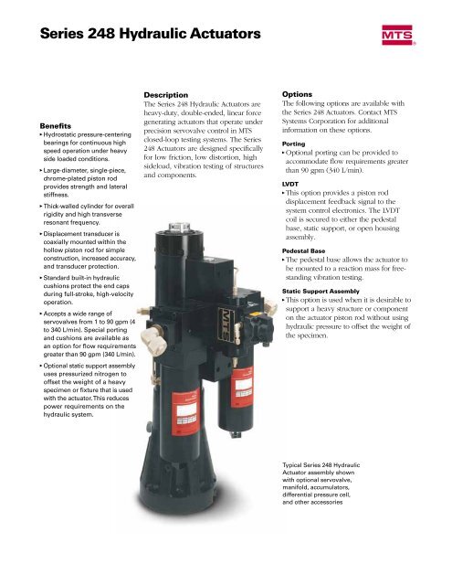
Description<br />
The <strong>Series</strong> <strong>248</strong> <strong>Hydraulic</strong> <strong>Actuators</strong> are<br />
heavy-duty, double-ended, linear force<br />
generating actuators that operate under<br />
pre cision servovalve control in <strong>MTS</strong><br />
closed- loop testing systems. The <strong>Series</strong><br />
<strong>248</strong> <strong>Actuators</strong> are designed specifically<br />
for low friction, low distortion, high<br />
sideload, vibration testing of structures<br />
and components.<br />
m<br />
Options<br />
The following options are available with<br />
the <strong>Series</strong> <strong>248</strong> Actua tors. Contact <strong>MTS</strong><br />
Systems Corporation for additional<br />
information on these options.<br />
Porting<br />
� Optional porting can be pro vided to<br />
accommodate flow requirements greater<br />
than 90 gpm (340 L/min).<br />
LVDT<br />
� This option provides a piston rod<br />
displacement feedback signal to the<br />
system control electronics. The LVDT<br />
coil is secured to either the pedestal<br />
base, static support, or open housing<br />
assembly.<br />
Pedestal Base<br />
� The pedestal base allows the actuator to<br />
be mounted to a reaction mass for freestanding<br />
vibration testing.<br />
Static Support Assembly<br />
� This option is used when it is desirable to<br />
support a heavy structure or component<br />
on the actuator piston rod without using<br />
hydraulic pressure to offset the weight of<br />
the specimen.<br />
Typical <strong>Series</strong> <strong>248</strong> <strong>Hydraulic</strong><br />
Actuator assembly shown<br />
with optional servovalve,<br />
manifold, accumulators,<br />
differential pressure cell,<br />
and other accessories
m<br />
m<br />
m<br />
<strong>248</strong> actuator & servovalve (S)<br />
Design Characteristics<br />
<strong>MTS</strong> actuators are manufactured to close<br />
tolerances to ensure reliability, long life,<br />
and complete part interchangeability<br />
(within a given actuator model). The<br />
following characteristics are common to<br />
all <strong>Series</strong> <strong>248</strong> <strong>Actuators</strong>.<br />
Piston Rod End (fixture attachment end)<br />
Has a center position internal thread and<br />
an internal thread circular hole pattern for<br />
mounting fixtures, vibration tables, wheel<br />
pans, load cell, etc.<br />
Porting<br />
<strong>Hydraulic</strong> fluid is ported into the actuator<br />
through the retraction port or the<br />
extension port. The fluid flow is regulated<br />
by a servovalve. As high hydraulic pressure<br />
is applied to one port, the other port is<br />
opened to a return line, resulting in actu ator<br />
rod displacement.<br />
Piston Rod<br />
The double-ended piston has equal areas<br />
on both sides for balanced performance.<br />
It is machined from a single piece of heattreated<br />
alloy steel, hard chrome plated,<br />
and precision ground to a fine finish to<br />
increase seal and bearing life. The hollow<br />
piston rod permits convenient installation<br />
and accu rate alignment of the LVDT.<br />
Piston Seal<br />
The close tolerance fit between the piston<br />
and cylinder provides an effective viscous<br />
seal. Grooves on the piston ensure<br />
adequate lubrication of the piston surface<br />
during short-stroke, sideloaded tests.<br />
Hydrostatic Bearings<br />
Each end cap contains four bearing pads<br />
which provide a strong centering force to<br />
counteract sideloads.<br />
Piston Rod Seals<br />
One seal assembly is provided in each<br />
end cap. This assembly contains a seal<br />
which guides excess hydraulic fluid to<br />
the drainback port, and a wiper which<br />
prevents external contamination from<br />
entering the actuator.<br />
Pedestal Base<br />
Allows the actuator to be mounted to a<br />
reaction mass for vibration testing.<br />
LVDT<br />
This assembly provides a signal proportional<br />
to actuator displacement. The LVDT core<br />
is secured inside the hol low piston rod<br />
by a core mount. On the pedestal base<br />
and open housing con fig urations, the<br />
core mount can be adjusted to establish a<br />
zero reference point for the actuator. The<br />
static support configuration has a fixed<br />
core mount to provide a mid-stroke zero<br />
reference point.<br />
Static Support (not shown)<br />
The <strong>Series</strong> <strong>248</strong> <strong>Actuators</strong> may be used in<br />
a static support configuration when it is<br />
desir able to support a heavy specimen or<br />
fixture on the piston rod without using<br />
hydraulic pressure to offset the weight of<br />
the specimen or the fixture. The static<br />
sup port assembly is mounted to the lower<br />
end cap of the actuator.<br />
Cutaway View of a Typical <strong>Series</strong> <strong>248</strong> Actuator
4 holes, "G" thread<br />
size, "H" deep,<br />
equally spaced on<br />
a "J" diameter.<br />
<strong>248</strong>.0X<br />
B (min.)<br />
"K" thread size<br />
"L" deep<br />
A<br />
Piston Rod End<br />
F (dia.)<br />
E (dia.)<br />
0.19 in. (4.8 mm)<br />
End Caps<br />
(both ends)<br />
M (dia.)<br />
8 holes, "G" thread<br />
size, "H" deep,<br />
equally spaced on<br />
a "J" diameter.<br />
"K" thread size,<br />
"L" deep<br />
<strong>248</strong>.1X, <strong>248</strong>.2X<br />
D<br />
(cushion)<br />
D<br />
(cushion)<br />
<strong>248</strong>.0X <strong>248</strong>.1X, <strong>248</strong>.2X<br />
4 holes, "N" thread size, "P" deep,<br />
equally spaced on a "Q" diameter.<br />
Basic Cylinder Assembly<br />
Dimensional Drawing<br />
Dynamic<br />
Stroke<br />
C<br />
(min.)<br />
Specifications<br />
Specifications for the <strong>Series</strong> <strong>248</strong> <strong>Actuators</strong> are listed<br />
according to actuator model numbers. Other<br />
tables list the dimensions for the basic cylinder<br />
assembly shown. The open housing and pedestal<br />
base configurations are shown on the next page.<br />
<strong>Series</strong> <strong>248</strong> Actuator Specifications<br />
Model Force Rating Piston Area Rod Diameter<br />
Kip kN in. 2 cm 2 in. mm<br />
<strong>248</strong>.01 2.2 10 0.81 5.23 3.15 80.0<br />
<strong>248</strong>.02 3.5 16 1.29 8.32 3.15 80.0<br />
<strong>248</strong>.03 6.2 28 2.25 14.52 3.15 80.0<br />
<strong>248</strong>.04 8.5 38 3.10 20.00 3.15 80.0<br />
<strong>248</strong>.05 11.0 50 3.98 25.67 3.15 80.0<br />
<strong>248</strong>.11 22.0 100 7.87 50.77 3.94 100.0<br />
<strong>248</strong>.12 35.0 160 12.60 81.29 3.94 100.1<br />
<strong>248</strong>.21 55.0 250 19.69 127.03 4.92 125.0<br />
Specifications are subject to change without notice. Contact <strong>MTS</strong> for verification of specifications critical to your needs.<br />
Basic Cylinder Assembly Dimensions (Stroke Length Dependent)<br />
Dynamic<br />
Stroke A B C D<br />
Length <strong>248</strong>.0X <strong>248</strong>.1X <strong>248</strong>.2X<br />
in. mm in. mm in. mm in. mm in. mm in. mm in. mm<br />
1 25.4 11.89 302.0 12.29 312.1 13.61 345.7 0.38 9.6 1.25 31.8 0.38 9.6<br />
2 50.8 12.89 327.4 13.29 337.5 14.61 371.1 0.38 9.6 1.25 31.8 0.38 9.6<br />
4 101.6 15.64 396.2 16.04 407.4 17.36 441.0 0.38 9.6 1.25 31.8 0.75 19.1<br />
6 152.4 17.64 448.0 18.04 458.2 19.36 491.8 0.38 9.6 1.25 31.8 0.75 19.1<br />
8 203.2 19.64 498.8 20.04 509.0 21.36 542.6 0.38 9.6 1.25 31.8 0.75 19.1<br />
10 254.0 21.64 549.6 22.04 559.8 23.36 593.4 0.38 9.6 1.25 31.8 0.75 19.1<br />
Specifications are subject to change without notice. Contact <strong>MTS</strong> for verification of specifications critical to your needs.<br />
Basic Cylinder Assembly Dimensions (Model Number Dependent)<br />
Model E F G H J K<br />
in. Basic mm Cylinder <strong>248</strong> in. mm in. mm in. mm<br />
<strong>248</strong>.0X 4.49 114.0 3.15 80.0 M12 x 1.75 mm 0.88 22.4 2.25 57.2 M27 x 2 mm<br />
<strong>248</strong>.1X 5.25 133.4 3.94 100.0 M12 x 1.75 mm 0.88 22.4 2.76 70.0 M27 x 2 mm<br />
<strong>248</strong>.2X 6.30 160.0 4.92 125.1 M16 x 2 mm 1.00 25.4 3.54 90.0 M36 x 3 mm<br />
Model L M N P Q<br />
in. mm in. mm in. mm in. mm<br />
<strong>248</strong>.0X 2.00 50.8 6.75 170.0 M20 x 2.5 mm 0.94 23.9 5.38 136.5<br />
<strong>248</strong>.1X 2.00 50.8 8.75 222.2 M24 x 3 mm 1.00 25.4 6.75 171.5<br />
<strong>248</strong>.2X 2.50 63.5 10.69 271.5 M24 x 3 mm 1.50 38.1 9.06 230.0<br />
Specifications are subject to change without notice. Contact <strong>MTS</strong> for verification of specifications critical to your needs.
Open Housing LVDT<br />
Dimensional Drawing<br />
Open House LVDT<br />
A<br />
A 1.00 in. (25.4 mm)<br />
<strong>MTS</strong> Systems Corporation<br />
14000 Technology Drive<br />
Eden Prairie, Minnesota 55344-2290 USA<br />
Toll Free: 800·328·2255<br />
Phone: 952·937·4000 Fax: 952·937·4515<br />
E-mail: info@mts.com<br />
www.mts.com<br />
ISO 9001 CerTIfIed QMS<br />
B<br />
1.25 in. (31.8 mm)<br />
Pedestal Base Dimension Drawing<br />
B<br />
2.18 in. (55.4 mm)<br />
4 threaded holes, "E" size,<br />
"F" deep, equally spaced<br />
on a "G" diameter<br />
8 holes, "C" diameter<br />
through, equally spaced<br />
on a "D" diameter<br />
Open Housing LVDT Dimensions<br />
Model A B<br />
Specifications subject to change without notice.<br />
<strong>MTS</strong> and RPC are registered trademarks of <strong>MTS</strong><br />
Systems Corporation. RTM No. 211177.<br />
© 1999 <strong>MTS</strong> Systems Corporation.<br />
100-016-994 HydAct<strong>248</strong>-01 Printed in U.S.A. 10/99<br />
m<br />
1 in. (25.4 mm) 4 in. (101.6 mm) 8 in. (203.2 mm)<br />
and and and<br />
2 in. (50.8 mm) 6 in. (152.4 mm) 10 in. (254.0 mm)<br />
Stroke Stroke Stroke<br />
in. mm in. mm in. mm in. mm<br />
<strong>248</strong>.0X 6.50 165.1 4.25 107.6 9.00 228.6 13.00 330.2<br />
<strong>248</strong>.1X 7.75 196.9 4.25 107.6 9.00 228.6 13.00 330.2<br />
<strong>248</strong>.2X 9.00 228.6 4.25 107.6 9.00 228.6 13.00 330.2<br />
Specifications are subject to change without notice. Contact <strong>MTS</strong> for verification of specifications critical to your needs.<br />
Pedestal Base Dimensions<br />
Model A B C D E F G<br />
in. mm in. mm in. mm in. mm in. mm in. mm<br />
<strong>248</strong>.0X 10.5 266.7 5.75 1<br />
146.1 1<br />
10.5 266.7 10.50 2 266.7 2<br />
10.5 266.7 14.50 3 368.3 3<br />
10.5 266.7 16.50 4 419.1 4<br />
<strong>248</strong>.1X 13.5 342.9 5.25 1<br />
133.4 1<br />
13.5 342.9 10.50 2 266.7 2<br />
13.5 342.9 14.50 3 368.3 3<br />
13.5 342.9 16.50 4 419.1 4<br />
<strong>248</strong>.2X 16.5 419.1 5.25 1<br />
133.4 1<br />
16.5 419.1 10.50 2 266.7 2<br />
16.5 419.1 14.50 3 368.3 3<br />
16.5 419.1 16.50 4 419.1 4<br />
1. Applies to actuators with 1 or 2 in. (25.4 or 50.8 mm) stroke.<br />
2. Applies to actuators with 4 or 6 in. (101.6 or 152.4 mm) stroke.<br />
3. Applies to actuators with 8 or 10 in. (203.2 or 254.0 mm) stroke.<br />
4. Applies to actuators with 12 in. (304.8 mm) stroke.<br />
0.53 13.5 9.00 228.6 3/4”-10 UNC-2B 1.0 25.4 9.0 228.6<br />
0.53 13.5 9.00 228.6 3/4”-10 UNC-2B 1.0 25.4 9.0 228.6<br />
0.53 13.5 9.00 228.6 3/4”-10 UNC-2B 1.0 25.4 9.0 228.6<br />
0.53 13.5 9.00 228.6 3/4”-10 UNC-2B 1.0 25.4 9.0 228.6<br />
0.66 16.8 11.81 300.0 1”-8 UNC-2B 1.5 38.1 11.0 279.4<br />
0.66 16.8 11.81 300.0 1”-8 UNC-2B 1.5 38.1 11.0 279.4<br />
0.66 16.8 11.81 300.0 1”-8 UNC-2B 1.5 38.1 11.0 279.4<br />
0.66 16.8 11.81 300.0 1”-8 UNC-2B 1.5 38.1 11.0 279.4<br />
0.91 23.1 14.57 370.0 – – – – –<br />
0.91 23.1 14.57 370.0 – – – – –<br />
0.91 23.1 14.57 370.0 – – – – –<br />
0.91 23.1 14.57 370.0 – – – – –<br />
5. Dimension is 5.25 in. (133.4 mm) for <strong>248</strong>.1X and <strong>248</strong>.2X actuators with a 1 in. (25.4 mm) or 2 in. (50.8 mm) stroke.<br />
This dimension and dimension 'B' are one and the same for these models.<br />
Ordering Information<br />
When ordering a <strong>Series</strong> <strong>248</strong> Actuator, first<br />
specify the desired basic cylinder assembly.<br />
The basic cylinder assembly is ordered<br />
by the model number corresponding to<br />
the desired force rating and the desired<br />
stroke length. Next, specify the desired<br />
Pedestal <strong>248</strong><br />
options as follows:<br />
� Special Porting<br />
� Open Housing LVDT Configuration<br />
� Pedestal Base Configuration<br />
� Static Support Configuration