XLogic SuperAnalogue Channel Owner's Manual - Solid State Logic
XLogic SuperAnalogue Channel Owner's Manual - Solid State Logic
XLogic SuperAnalogue Channel Owner's Manual - Solid State Logic

You also want an ePaper? Increase the reach of your titles
YUMPU automatically turns print PDFs into web optimized ePapers that Google loves.
Operation<br />
DYNAMICS<br />
COMPRESSOR<br />
RELEASE<br />
GATE<br />
THRESHOLD<br />
HOLD<br />
DYN<br />
IN<br />
PRE<br />
EQ<br />
0<br />
PK<br />
1 4<br />
THRESHOLD<br />
3 6 10<br />
RATIO<br />
14<br />
20<br />
3<br />
0<br />
RELEASE<br />
+10<br />
0<br />
EXP<br />
RANGE<br />
0<br />
4<br />
KEY<br />
LINK<br />
FAST<br />
ATT<br />
+10 -20<br />
1<br />
1<br />
4<br />
FAST<br />
ATT<br />
0 40<br />
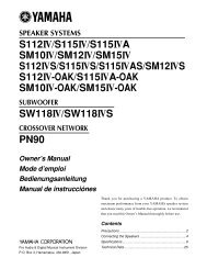
4.2 Dynamics Section<br />
The Dynamics section comprises a compressor/limiter and an expander/gate, both of which use the same<br />
gain change element. Both sections work independently, but can be operational at the same time,<br />
providing sophisticated control of signal levels. The Filter and/or the Equaliser section can be assigned to<br />
the dynamics side chain allowing de-essing etc.<br />
The Dynamics section has two routing buttons associated with it. Section 5 deals with Dynamics routing<br />
in more detail, but briefly these button function as follows:<br />
DYN IN – Switches the Dynamics section into the signal path pre the EQ.<br />
PRE EQ – Switches the Dynamics section pre the EQ section (but post the Filter section if the Filter INPUT<br />
switch is pressed).<br />
KEY – Switches the Dynamics side chain to the ‘KEY’ input on the rear panel of the unit.<br />
If you have more than one unit and have connected the ‘DYN LINK’ jacks on the rear of the units together<br />
the side chain control signals of multiple units can be linked by pressing the LINK switch on those units<br />
you wish to gang. When two Dynamics sections are linked, the control voltages of each section sum<br />
together, so that whichever section has the most gain reduction will control the other section.<br />
Don’t try to link two gates using the LINK button when you want the signal on one to open the other. If<br />
you need to achieve this effect, take a keying signal from one section to trigger the other. The easiest way<br />
to do this is by patching from the output of the ‘source’ channel into the Key input of the ‘destination’<br />
channel, and selecting KEY (see above) on this channel.<br />
4.3 Compressor/Limiter<br />
RATIO – When turned to 1:1, the Compressor/Limiter section is inactive. Turning the control clockwise<br />
increases the compression ratio to give a true limiter at the fully clockwise position.<br />
The compressor normally has an ‘over-easy’ characteristic. Selecting PK changes this to peak sensing, and<br />
replaces the ’over–easy’ characteristic with a hard knee, providing an alternative for some instruments.<br />
THRESHOLD – Whenever a signal exceeds the level set by this control, the compressor will start to act<br />
at the ratio set by the RATIO control. This control also provides automatic make-up gain, so as you lower<br />
the threshold and introduce more compression, the output level is increased, maintaining a steady output<br />
level regardless of the amount of compression.<br />
RELEASE – Sets the time constant (speed) with which the compressor returns to normal gain settings once<br />
the signal has passed its maximum.<br />
FAST ATT – Provides a fast attack time (3mS for 20dB gain reduction). When off the attack time is<br />
program dependent (3mS – 30mS).<br />
The yellow and red LEDs, on the bottom of the LED display area, indicate the amount of gain reduction<br />
(compression).<br />
Page 9