current_userManual - Audio Rents
current_userManual - Audio Rents
current_userManual - Audio Rents

Create successful ePaper yourself
Turn your PDF publications into a flip-book with our unique Google optimized e-Paper software.
DMA8Plus Digital<br />
Media Adapter<br />
Installation and User’s<br />
Manual<br />
Issue 3 Part Number 91805
Dolby Laboratories, Inc.<br />
Corporate Headquarters<br />
Dolby Laboratories, Inc.<br />
100 Potrero Avenue<br />
San Francisco, CA 94103‐4813 USA<br />
Telephone 415‐558‐0200<br />
Fax 415‐863‐1373<br />
www.dolby.com<br />
European Headquarters<br />
Dolby Laboratories, Inc.<br />
Wootton Bassett<br />
Wiltshire SN4 8QJ England<br />
Telephone 44‐1793‐842100<br />
Fax 44‐1793‐842101<br />
DISCLAIMER OF WARRANTIES:<br />
EQUIPMENT MANUFACTURED BY DOLBY LABORATORIES IS WARRANTED AGAINST DEFECTS<br />
IN MATERIALS AND WORKMANSHIP FOR A PERIOD OF ONE YEAR FROM THE DATE OF<br />
PURCHASE. THERE ARE NO OTHER EXPRESS OR IMPLIED WARRANTIES AND NO WARRANTY<br />
OF MERCHANTABILITY OR FITNESS FOR A PARTICULAR PURPOSE, OR OF NONINFRINGEMENT<br />
OF THIRD‐PARTY RIGHTS (INCLUDING, BUT NOT LIMITED TO, COPYRIGHT AND PATENT<br />
RIGHTS).<br />
LIMITATION OF LIABILITY:<br />
IT IS UNDERSTOOD AND AGREED THAT DOLBY LABORATORIES’ LIABILITY, WHETHER IN<br />
CONTRACT, IN TORT, UNDER ANY WARRANTY, IN NEGLIGENCE, OR OTHERWISE, SHALL NOT<br />
EXCEED THE COST OF REPAIR OR REPLACEMENT OF THE DEFECTIVE COMPONENTS OR<br />
ACCUSED INFRINGING DEVICES, AND UNDER NO CIRCUMSTANCES SHALL DOLBY<br />
LABORATORIES BE LIABLE FOR INCIDENTAL, SPECIAL, DIRECT, INDIRECT, OR<br />
CONSEQUENTIAL DAMAGES (INCLUDING, BUT NOT LIMITED TO, DAMAGE TO SOFTWARE OR<br />
RECORDED AUDIO OR VISUAL MATERIAL), COST OF DEFENSE, OR LOSS OF USE, REVENUE, OR<br />
PROFIT, EVEN IF DOLBY LABORATORIES OR ITS AGENTS HAVE BEEN ADVISED, ORALLY OR IN<br />
WRITING, OF THE POSSIBILITY OF SUCH DAMAGES.<br />
Dolby, Pro Logic, and the double‐D symbol are registered trademarks of Dolby Laboratories. Part Number 91805<br />
All other trademarks remain the property of their respective owners. Issue 3<br />
© 2008 Dolby Laboratories. All rights reserved. S08/18506/19457<br />
ii<br />
Dolby ® DMA8Plus Digital Media Adapter Installation and User’s Manual
Regulatory Notices<br />
FCC<br />
NOTE: This equipment has been tested and found to comply with the limits for a Class A<br />
digital device, pursuant to Part 15 of the FCC Rules. These limits are designed to provide<br />
reasonable protection against harmful interference when the equipment is operated in a<br />
commercial environment. This equipment generates, uses, and can radiate radio frequency<br />
energy and, if not installed and used in accordance with this instruction manual, may cause<br />
harmful interference to radio communications. Operation of this equipment in a residential<br />
area is likely to cause harmful interference in which case the user will be required to correct<br />
the interference at his own expense.<br />
Canada<br />
This Class A digital apparatus complies with Canadian ICES‐003.<br />
EU/EMC<br />
This unit complies with the EMC requirement of EN55103‐1 and EN55103‐2 when operated<br />
in an E2 environment in accordance with this manual.<br />
Important Safety Instructions<br />
1. Read these instructions.<br />
2. Keep these instructions.<br />
3. Heed all warnings.<br />
4. Follow all instructions.<br />
5. Do not use this apparatus near water.<br />
6. WARNING: To reduce the risk of fire or electric shock, do not expose this apparatus to<br />
rain or moisture.<br />
7. Clean only with dry cloth.<br />
8. Do not install near any heat sources such as radiators, heat registers, stoves, or other<br />
apparatus (including amplifiers) that produce heat.<br />
9. No naked flame sources, such as lighted candles, should be placed on the apparatus<br />
10. Protect the power cord from being walked on or pinched particularly at plugs,<br />
convenience receptacles, and the point where they exit from the apparatus.<br />
11. Only use attachments/accessories specified by the manufacturer.<br />
12. Unplug this apparatus during lightning storms or when unused for long periods of<br />
time.<br />
13. Refer all servicing to qualified service personnel. Servicing is required when the<br />
apparatus has been damaged in any way, such as power‐supply cord or plug is<br />
damaged, liquid has been spilled or objects have fallen into the apparatus, the<br />
apparatus has been exposed to rain or moisture, does not operate normally, or has<br />
been dropped.<br />
14. Do not expose the apparatus to dripping or splashing and no objects filled with<br />
liquids, such as vases, shall be placed on the apparatus.<br />
Dolby ® DMA8Plus Digital Media Adapter Installation and User’s Manual Issue 3 Preliminary 0.92<br />
iii
Regulatory Notices<br />
15. CAUTION: Troubleshooting must be performed by a trained technician. To reduce the<br />
risk of electric shock, do not attempt to service this equipment unless you are<br />
qualified to do so.<br />
16. Do not defeat the safety purpose of the polarized or grounding‐type plug. A polarized<br />
plug has two blades with one wider than the other. A grounding type plug has two<br />
blades and a third grounding prong. The wide blade or the third prong is provided<br />
for your safety. If the provided plug does not fit into your outlet, consult an electrician<br />
for replacement of the obsolete outlet.<br />
17. This apparatus must be earthed (grounded) by connecting to a correctly wired and<br />
earthed power outlet.<br />
18. Ensure that your mains supply is in the correct range for the input power requirement<br />
of the unit.<br />
19. In order to reduce the risk of electrical shock, the power cord must be disconnected<br />
when the power supply assembly is removed.<br />
20. This equipment is designed to mount in a suitably ventilated 19” rack; ensure that any<br />
ventilation slots in the unit are not blocked or covered.<br />
21. The mains power disconnect device for this unit is the plug‐in mains cord rather than<br />
a power switch. The mains cord must remain readily accessible for disconnecting<br />
mains power.<br />
22. To avoid exposure to dangerous voltages and to avoid damage to the unit, do not<br />
connect the rear‐panel Ethernet port to telephone circuits.<br />
23. As the colours of the cores in the mains lead may not correspond with the coloured<br />
markings identifying the terminals in your plug, proceed as follows:<br />
• The green and yellow core must be connected to the terminal in the plug<br />
identified by the letter E, or by the earth symbol , or coloured green, or green<br />
and yellow.<br />
• The blue core must be connected to the terminal marked with the letter N or<br />
coloured black.<br />
• The brown core must be connected to the terminal marked with the letter L or<br />
coloured red.<br />
24. This apparatus must be earthed.<br />
Fuses<br />
WARNING: Check that the correct fuses have been installed. For continued protection<br />
against risk of fire, replace only with fuses of the same type and rating. For details on fuse<br />
ratings and instructions on fuse replacement, see Checking the Two User‐Serviceable Fuses<br />
on page 10.<br />
WEEE<br />
PRODUCT END‐OF‐LIFE INFORMATION<br />
This product was designed and built by Dolby Laboratories to provide many years of<br />
service, and is backed by our commitment to provide high‐quality support. When it<br />
eventually reaches the end of its serviceable life, it should be disposed of in accordance<br />
with local or national legislation.<br />
For <strong>current</strong> information please visit our website at: http://www.dolby.com/environment.<br />
iv<br />
Dolby ® DMA8Plus Digital Media Adapter Installation and User’s Manual
Regulatory Notices<br />
IMPORTANT SAFETY NOTICE<br />
This unit complies with safety standard EN60065 as appropriate. The unit shall not be exposed to dripping or splashing and no objects filled with liquids, such as<br />
coffee cups, shall be placed on the equipment. To ensure safe operation and to guard against potential shock hazard or risk of fire, the following must be<br />
observed:<br />
o Ensure that your mains supply is in the correct range for the input power requirement of the unit.<br />
o Ensure fuses fitted are the correct rating and type as marked on the unit.<br />
o The unit must be earthed by connecting to a correctly wired and earthed power outlet.<br />
o The power cord supplied with this unit must be wired as follows:<br />
Live—Brown Neutral—Blue Earth—Green/Yellow<br />
GB<br />
IMPORTANT – NOTE DE SECURITE<br />
Ce materiel est conforme à la norme EN60065. Ne pas exposer cet appareil aux éclaboussures ou aux gouttes de liquide. Ne pas poser dʹobjets remplis de liquide, tels que des<br />
tasses de café, sur lʹappareil. Pour vous assurer dʹun fonctionnement sans danger et de prévenir tout choc électrique ou tout risque dʹincendie, veillez à observer<br />
les recommandations suivantes.<br />
F<br />
o Le selecteur de tension doit être placé sur la valeur correspondante à votre alimentation réseau.<br />
o Les fusibles doivent correspondre à la valeur indiquée sur le materiel.<br />
o Le materiel doit être correctement relié à la terre.<br />
o Le cordon secteur livré avec le materiel doit être cablé de la manière suivante:<br />
Phase—Brun Neutre—Bleu Terre—Vert/Jaune<br />
WICHTIGER SICHERHEITSHINWEIS<br />
Dieses Gerät entspricht der Sicherheitsnorm EN60065. Das Gerät darf nicht mit Flüssigkeiten (Spritzwasser usw.) in Berührung kommen; stellen Sie keine Gefäße, z.B.<br />
Kaffeetassen, auf das Gerät. Für das sichere Funktionieren des Gerätes und zur Unfallverhütung (elektrischer Schlag, Feuer) sind die folgenden Regeln unbedingt<br />
einzuhalten:<br />
o Der Spannungswähler muß auf Ihre Netzspannung eingestellt sein.<br />
D<br />
o Die Sicherungen müssen in Typ und Stromwert mit den Angaben auf dem Gerät übereinstimmen.<br />
o Die Erdung des Gerätes muß über eine geerdete Steckdose gewährleistet sein.<br />
o Das mitgelieferte Netzkabel muß wie folgt verdrahtet werden:<br />
Phase—braun Nulleiter—blau Erde—grün/gelb<br />
NORME DI SICUREZZA – IMPORTANTE<br />
Questa apparecchiatura è stata costruita in accordo alle norme di sicurezza EN60065. Il prodotto non deve essere sottoposto a schizzi, spruzzi e gocciolamenti, e nessun tipo di<br />
oggetto riempito con liquidi, come ad esempio tazze di caffè, deve essere appoggiato sul dispositivo. Per una perfetta sicurezza ed al fine di evitare eventuali rischi di scossa<br />
êlettrica o dʹincendio vanno osservate le seguenti misure di sicurezza:<br />
o Assicurarsi che il selettore di cambio tensione sia posizionato sul valore corretto.<br />
o Assicurarsi che la portata ed il tipo di fusibili siano quelli prescritti dalla casa costruttrice.<br />
I<br />
o Lʹapparecchiatura deve avere un collegamento di messa a terra ben eseguito; anche la connessione rete deve<br />
avere un collegamento a terra.<br />
o Il cavo di alimentazione a corredo dellʹapparecchiatura deve essere collegato come segue:<br />
Filo tensione—Marrone Neutro—Blu Massa—Verde/Giallo<br />
AVISO IMPORTANTE DE SEGURIDAD<br />
Esta unidad cumple con la norma de seguridad EN60065. La unidad no debe ser expuesta a goteos o salpicaduras y no deben colocarse sobre el equipo recipientes con liquidos,<br />
como tazas de cafe. Para asegurarse un funcionamiento seguro y prevenir cualquier posible peligro de descarga o riesgo de incendio, se han de observar las<br />
siguientes precauciones:<br />
o Asegúrese que el selector de tensión esté ajustado a la tensión correcta para su alimentación.<br />
E<br />
o Asegúrese que los fusibles colocados son del tipo y valor correctos, tal como se marca en la unidad.<br />
o La unidad debe ser puesta a tierra, conectándola a un conector de red correctamente cableado y puesto a tierra.<br />
o El cable de red suministrado con esta unidad, debe ser cableado como sigue:<br />
Vivo—Marrón Neutro—Azul Tierra—Verde/Amarillo<br />
VIKTIGA SÄKERHETSÅTGÄRDER!<br />
Denna enhet uppfyller säkerhetsstandard EN60065. Enheten får ej utsättas för yttre åverkan samt föremål innehållande vätska, såsom kaffemuggar, får ej placeras på<br />
utrustningen. För att garantera säkerheten och gardera mot eventuell elchock eller brandrisk, måste följande observeras:<br />
o Kontrollera att spänningsväljaren är inställd på korrekt nätspänning.<br />
o Konrollera att säkringarna är av rätt typ och för rätt strömstyrka så som anvisningarna på enheten föreskriver.<br />
S<br />
o Enheten måste vara jordad genom anslutning till ett korrekt kopplat och jordat el‐uttag.<br />
o El‐sladden som medföljer denna enhet måste kopplas enligt foljande:<br />
Fas—Brun Neutral—Blå Jord—Grön/Gul<br />
BELANGRIJK VEILIGHEIDS‐VOORSCHRIFT:<br />
Deze unit voldoet aan de EN60065 veiligheids‐standaards. Dit apparaat mag niet worden blootgesteld aan vocht. Vanwege het risico dat er druppels in het apparaat vallen, dient<br />
u er geen vloeistoffen in bekers op te plaatsen. Voor een veilig gebruik en om het gevaar van electrische schokken en het risico van brand te vermijden, dienen de<br />
volgende regels in acht te worden genomen:<br />
o Controleer of de spanningscaroussel op het juiste Voltage staat.<br />
NL<br />
o Gebruik alleen zekeringen van de aangegeven typen en waarden.<br />
o Aansluiting van de unit alleen aan een geaarde wandcontactdoos.<br />
o De netkabel die met de unit wordt geleverd, moet als volgt worden aangesloten:<br />
Fase—Bruin Nul—Blauw Aarde—Groen/Geel<br />
Dolby ® DMA8Plus Digital Media Adapter Installation and User’s Manual<br />
v
Table of Contents<br />
Introduction ................................................................................................................................. 1<br />
1.1 DMA8Plus Front Panel .........................................................................................................2<br />
1.1.1 Digital Input Push Buttons........................................................................................2<br />
1.1.2 Film Push Button......................................................................................................3<br />
1.1.3 Valid Input Clock .....................................................................................................3<br />
1.1.4 Output Activity LEDs ................................................................................................3<br />
1.1.5 Format LEDs............................................................................................................3<br />
1.1.6 Decode Mode LEDs.................................................................................................3<br />
1.1.7 USB Port ..................................................................................................................3<br />
1.2 DMA8Plus Rear Panel..........................................................................................................4<br />
1.2.1 To CP Control Connector.........................................................................................4<br />
1.2.2 To DA Control Connector.........................................................................................4<br />
1.2.3 4xAES Input (AES/EBU) ..........................................................................................5<br />
1.2.4 1xAES Inputs (AES3)...............................................................................................5<br />
1.2.5 S/PDIF Optical Input ................................................................................................5<br />
1.2.6 Digital Media Automation Connector .......................................................................5<br />
1.2.7 RS-232 Serial Port ...................................................................................................5<br />
1.2.8 Ethernet Port............................................................................................................5<br />
1.2.9 <strong>Audio</strong> Out to CP Connector .....................................................................................6<br />
1.2.10 Analog <strong>Audio</strong> In Connector......................................................................................6<br />
Installation and Maintenance..................................................................................................... 7<br />
2.1 DMA8Plus Floating Signal Grounds .....................................................................................7<br />
2.2 Digital <strong>Audio</strong> Inputs...............................................................................................................7<br />
2.2.1 Consumer Interface Standards for Digital <strong>Audio</strong>......................................................8<br />
2.2.2 Cable Issues ............................................................................................................8<br />
2.2.3 Multiple Sources: Conversion Between Interface Standards...................................8<br />
2.3 Connections..........................................................................................................................9<br />
2.4 Fuse Information...................................................................................................................9<br />
2.4.1 Checking the Two User-Serviceable Fuses...........................................................10<br />
2.5 Mains Power Wiring............................................................................................................11<br />
2.6 Wiring Diagrams .................................................................................................................11<br />
Setting up the DMA8Plus .........................................................................................................19<br />
3.1 DMA8Plus Setup Software ................................................................................................19<br />
3.2 Installing and Running the Setup Software.........................................................................20<br />
3.3 Profile .................................................................................................................................20<br />
3.3.1 Profile Settings.......................................................................................................21<br />
3.3.2 Virtual Status Monitor.............................................................................................21<br />
3.4 Network...............................................................................................................................22<br />
3.5 Digital Inputs 1, 2, 3, and 4 .................................................................................................23<br />
3.5.1 Global Delay ..........................................................................................................24<br />
3.5.2 PCM Settings .........................................................................................................24<br />
Dolby ® DMA8Plus Digital Media Adapter Installation and User’s Manual<br />
vii
Table of Contents<br />
3.5.3 Dolby Digital Settings.............................................................................................25<br />
3.5.4 Dolby E Settings ....................................................................................................26<br />
3.6 General Settings .................................................................................................................27<br />
3.6.1 CP Settings ............................................................................................................27<br />
3.6.2 Surround Delay ......................................................................................................28<br />
3.6.3 Pro Logic/Pro Logic II Subwoofer ..........................................................................28<br />
3.6.4 Power-on Mode......................................................................................................28<br />
3.7 File Menu ............................................................................................................................29<br />
3.7.1 Loading Settings ....................................................................................................29<br />
3.7.2 Saving Settings ......................................................................................................29<br />
3.8 Action Menu........................................................................................................................30<br />
3.8.1 Connecting to a Local or Remote Device ..............................................................30<br />
3.8.2 Update Software ....................................................................................................31<br />
3.9 Window Menu .....................................................................................................................31<br />
3.10 Updating the DMA8Plus Firmware......................................................................................32<br />
Technical Reference ................................................................................................................. 33<br />
4.1 DMA8Plus Specifications....................................................................................................33<br />
4.2 Rear-Panel Connector Descriptions and Types..................................................................36<br />
4.2.1 Digital Media Automation Connector .....................................................................36<br />
4.2.2 Analog <strong>Audio</strong> In/Out Connectors ...........................................................................36<br />
4.2.3 4xAES In Connector ..............................................................................................38<br />
4.2.4 Remote RS-232 Serial Port ...................................................................................39<br />
4.2.5 Automation Connections—CP55 with Cat. No. 321 Interface................................39<br />
4.2.6 Cinema Processor Automation Pin Assignments ..................................................40<br />
4.2.7 RS-232 ASCII String Commands...........................................................................42<br />
4.2.8 To CP Control Pinouts ...........................................................................................42<br />
4.2.9 DMA8Plus <strong>Audio</strong> Out to CP Pinouts ......................................................................44<br />
4.3 Remote Commands and Control ........................................................................................45<br />
4.3.1 Serial......................................................................................................................45<br />
4.3.2 Ethernet .................................................................................................................46<br />
viii<br />
Dolby ® DMA8Plus Digital Media Adapter Installation and User’s Manual
List of Figures<br />
Figure 1-1 DMA8Plus Front Panel .......................................................................................................... 2<br />
Figure 1-2 DMA8Plus Rear Panel........................................................................................................... 4<br />
Figure 2-1 Checking the User-Serviceable Fuses ................................................................................ 10<br />
Figure 3-1 Installation Welcome Screen ............................................................................................... 20<br />
Figure 3-2 Profile Settings Window....................................................................................................... 21<br />
Figure 3-3 Ethernet Settings Window ................................................................................................... 22<br />
Figure 3-4 Digital Input 1 Window......................................................................................................... 23<br />
Figure 3-5 Digital Input 2 Window......................................................................................................... 24<br />
Figure 3-6 General Settings Window .................................................................................................... 27<br />
Figure 3-7 Selecting Open in the File Menu ......................................................................................... 29<br />
Figure 3-8 Selecting Save in the File Menu .......................................................................................... 29<br />
Figure 3-9 Action Menu......................................................................................................................... 30<br />
Figure 3-10 Connect to Remote DMA8Plus Prompt ............................................................................... 30<br />
Figure 3-11 Window Menu...................................................................................................................... 31<br />
Figure 3-12 Expert View Window............................................................................................................ 31<br />
Figure 3-13 Dolby Software Update Screen ........................................................................................... 32<br />
Dolby ® DMA8Plus Digital Media Adapter Installation and User’s Manual<br />
ix
List of Figures<br />
x<br />
Dolby ® DMA8Plus Digital Media Adapter Installation and User’s Manual
List of Tables<br />
Table 1-1 Digital Push Button Functionality............................................................................................2<br />
Table 2-1 Examples of Available Balanced/Unbalanced Adapters.........................................................9<br />
Table 4-1 Rear-Panel Connector Descriptions and Types ...................................................................36<br />
Table 4-2 Digital Media Connector Pinout ............................................................................................36<br />
Table 4-3 Analog <strong>Audio</strong> In/Out Connector Pinout.................................................................................37<br />
Table 4-4 4xAES In Connector Pinout..................................................................................................38<br />
Table 4-5 Serial Port Pinout..................................................................................................................39<br />
Table 4-6 CP55 with Cat. No. 321 Automation Interface Card Installed...............................................39<br />
Table 4-7 S0–S7 CP Automation Digital Mode Defaults (digital 1–4 defaults shaded).........................40<br />
Table 4-8 S0–S7 CP Automation Film Mode Format Defaults (film defaults shaded)..........................41<br />
Table 4-9 ASCII String Commands ......................................................................................................42<br />
Table 4-10 To CP Control (25-pin D output)...........................................................................................42<br />
Table 4-11 <strong>Audio</strong> Out to CP Cables (Cat. No. 757 dongle grounds shaded) .........................................45<br />
Dolby ® DMA8Plus Digital Media Adapter Installation and User’s Manual<br />
xi
List of Tables<br />
xii<br />
Dolby ® DMA8Plus Digital Media Adapter Installation and User’s Manual
Chapter 1<br />
Introduction<br />
The Dolby ® DMA8Plus Digital Media Adapter is a direct result of Dolby Laboratories’<br />
continued leadership in the development of innovative cinema technologies. The<br />
DMA8Plus provides all the interface capabilities and digital inputs you’re likely to need.<br />
With the DMA8Plus, you can adapt your existing sound system for digital cinema and<br />
other digital audio sources. The unit provides a straightforward interface to existing Dolby<br />
cinema equipment, such as the CP650, CP500, CP65, CP55, CP45, CP200, and DA20. In<br />
addition, the DMA8Plus provides theatres with audio solutions to today’s alternative<br />
programming challenges, such as pay‐per‐view events and digital broadcasting.<br />
The DMA8Plus has four separate digital inputs and accepts up to eight channels of PCM<br />
digital audio as well as Dolby Digital and Dolby E bitstreams. Two‐channel audio sources<br />
can be decoded as discrete, Dolby Pro Logic ® , or Dolby Pro Logic II signals. Analog audio<br />
outputs are calibrated to cinema processor reference levels to ensure a straightforward<br />
interface with your cinema’s existing sound processor.<br />
With the DMA8Plus, you can present high‐quality audio from the following audio sources<br />
and formats:<br />
• Dolby Digital Cinema<br />
• Onscreen advertising servers<br />
• Digital VTRs<br />
• Digital satellite or cable TV receivers<br />
• DVDs<br />
• PCM<br />
• Dolby Digital consumer bitstreams<br />
• Dolby E<br />
A separate adjustable global audio delay is assigned to each digital input to ensure that<br />
sound and picture are perfectly synchronized during digital cinema presentations.<br />
Different delays can be assigned to different inputs, providing flexibility for alternative<br />
content sources, which often require different delays.<br />
The DMA8Plus is also compatible with existing theatre automation systems and ASCII<br />
command strings. Its ability to handle multiple formats and future upgrades make it an<br />
essential tool for an evolving digital cinema market.<br />
The DMA8Plus is designed to fit between an existing DA20 (Dolby Digital film decoder)<br />
and a cinema processor. This allows both the DA20 and DMA8Plus to share the six‐channel<br />
input of the cinema processor. When the DMA8Plus is in Film mode, standard six‐channel<br />
analog signals from any source, such as a Dolby DA20, are routed through the DMA8Plus<br />
to the six‐channel input of a cinema sound processor (pass‐through). In one of the four<br />
digital modes, the DMA8Plus decodes and routes signals from a variety of nonfilm sources<br />
to the existing cinema sound processor.<br />
Dolby ® DMA8Plus Digital Media Adapter Installation and User’s Manual 1
Introduction<br />
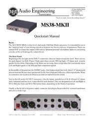
1.1 DMA8Plus Front Panel<br />
The DMA8Plus front panel includes the following components:<br />
• Five push buttons to select the input source (digital 1, digital 2, digital 3, digital 4, or<br />
film)<br />
• Four LEDs that indicate a valid clock presence for each digital input<br />
• Four LEDs that indicate the <strong>current</strong> format (PCM, Dolby Digital, Dolby E, or<br />
Aux [auxiliary])<br />
• Three LEDs that indicate the decode mode (Pro Logic II, Pro Logic, or Discrete)<br />
• Eight LEDs that monitor the eight‐channel analog audio output activity (L, C, R, Sw,<br />
Ls, Rs, 7 and 8)<br />
• One USB port for firmware upgrades and setup software<br />
Figure 1‐1<br />
Figure 1-1<br />
DMA8Plus Front Panel<br />
1.1.1 Digital Input Push Buttons<br />
When you press any of the digital 1, digital 2, digital 3, or digital 4 push buttons, that button<br />
illuminates, indicating that the selected input is active until you press one of the other push<br />
buttons. Pressing a push button selects a specific digital input source, as shown in<br />
Table 1‐1. The DMA8Plus sends a format pulse to the cinema processor to switch the<br />
processor into the appropriate six‐channel input format (see Table 4‐7).<br />
Note:<br />
Be sure to use a control cable to connect the cinema processor to the DMA8Plus<br />
TO CP CONTROL connector.<br />
When in a digital mode, the DMA8Plus can switch between PCM, Dolby Digital, or Dolby<br />
E encoded bitstreams.<br />
Table 1-1<br />
Digital Push Button Functionality<br />
Digital Push<br />
Button<br />
digital 1<br />
digital 2<br />
digital 3<br />
digital 4<br />
Input Source Selected<br />
Selects the digital input source from the 4xAES digital input 1 (four‐channel<br />
pairs, 25‐pin D‐connector)<br />
Selects the digital input source from the 1xAES digital input 2 (BNC)<br />
Selects the digital input source from the 1xAES digital input 3 (BNC)<br />
Selects the digital input source from the 1xAES digital input 4 (S/PDIF<br />
optical)<br />
2 Dolby ® DMA8Plus Digital Media Adapter Installation and User’s Manual
DMA8Plus Front Panel<br />
1.1.2 Film Push Button<br />
When you press this button it illuminates, indicating that film mode is active. When the<br />
DMA8Plus is in Film mode, audio is received from the analog audio input, which then<br />
passes through to the analog audio output (while the unit is in Film mode or when<br />
powered off). The DMA8Plus sends a format pulse to the cinema processor to enable an<br />
appropriate format (see Table 4‐8). When you press any cinema processor format button,<br />
the DMA8Plus switches to Film mode without sending its Film mode pulse assertion.<br />
Note:<br />
Be sure to use a control cable to connect the cinema processor to the DMA8Plus<br />
TO CP CONTROL connector.<br />
1.1.3 Valid Input Clock<br />
Each of the four digital input push buttons has a green valid LED located beneath it. These<br />
LEDs illuminate when a valid input clock signal is detected on the respective input<br />
(regardless of whether the corresponding button is selected).<br />
1.1.4 Output Activity LEDs<br />
There are eight signal‐level LEDs, one for each channel. The signals are monitored after the<br />
D/A converter output, and before the output relays. The LEDs vary in intensity and are<br />
brightest at +20 dBr (r = 300 mV), while turning off at approximately –26 dBr.<br />
1.1.5 Format LEDs<br />
There are four bitstream format LEDs (PCM, Dolby Digital, Dolby E, and Aux). The Aux<br />
format is <strong>current</strong>ly reserved for future use. These LEDs illuminate when the DMA8Plus is<br />
actually receiving the respective data format.<br />
1.1.6 Decode Mode LEDs<br />
There are three bitstream processing LEDs, indicating the decode mode (Pro Logic II, Pro<br />
Logic, and Discrete).<br />
1.1.7 USB Port<br />
The USB port is provided for connecting to a PC. You can use it to set up or update the<br />
DMA8Plus firmware.<br />
Dolby ® DMA8Plus Digital Media Adapter Installation and User’s Manual 3
Introduction<br />
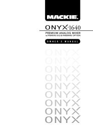
1.2 DMA8Plus Rear Panel<br />
The DMA8Plus rear panel includes the following components:<br />
• AC input<br />
• TO CP CONTROL (25‐pin male D‐connector for cinema processor format interface)<br />
• TO DA CONTROL (25‐pin female D‐connector for DA20 processor interface)<br />
• One 4xAES (AES/EBU) digital input (25‐pin female D‐connector)<br />
• Two 1xAES (AES3) digital inputs (BNC)<br />
• One OPTICAL (S/PDIF) digital input (Toslink TM connector)<br />
• DIGITAL MEDIA AUTOMATION (9‐pin female D‐connector from cinema automation<br />
control)<br />
• RS-232 port (9‐pin female D‐connector for control via ASCII command strings)<br />
• 10BASE-T (RJ45 Ethernet port for control through ASCII command strings, Dolby<br />
Digital cinema systems, and setup/updates)<br />
• AUDIO OUT TO CP (25‐pin male D‐connector balanced audio to cinema processor)<br />
• ANALOG AUDIO IN (25‐pin female D‐connector audio from DA20)<br />
Figure 1‐2<br />
Digital Media Adapter<br />
DMA8Plus<br />
TO CP CONTROL<br />
4xAES IN<br />
1xAES<br />
1xAES<br />
OPTICAL<br />
DIGITAL MEDIA<br />
AUTOMATION<br />
AUDIO OUT TO CP<br />
100–240 Vac ~ 50–60Hz 15W<br />
Dolby, Pro Logic and the double-D symbol<br />
are registered trademarks of Dolby Laboratories.<br />
TO DA CONTROL<br />
DIGITAL 1 IN<br />
DIGITAL 2 IN<br />
DIGITAL 3 IN<br />
DIGITAL 4 IN<br />
RS-232<br />
ACT<br />
10BASE-T<br />
LINK<br />
ANALOG AUDIO IN<br />
Figure 1-2<br />
DMA8Plus Rear Panel<br />
1.2.1 To CP Control Connector<br />
This connector is a 25‐pin male D‐connector for connecting to a Dolby cinema processor’s<br />
automation input. It has a floating ground. This output performs the following functions:<br />
• Prevents a DA20 from reverting the cinema processor to a Dolby SR format while the<br />
DMA8Plus is in a digital mode utilizing the cinema processor in Format 10<br />
• Enables the DMA8Plus to send a film or digital format command to the cinema<br />
processor to switch the processor to an associated format<br />
• Enables the DMA8Plus to receive and activate a film command from a cinema<br />
processor when the processor’s format button is activated<br />
Note:<br />
A cable kit is available for connecting the DMA8Plus to a CP650 or CP500 along<br />
with your existing automation connection. The kit includes a custom audio cable<br />
(shielded/twisted pairs) and a shielded automation cable. If you require this kit,<br />
order CDMA/D.<br />
1.2.2 To DA Control Connector<br />
This is a 25‐pin female D‐connector for interfacing to a Dolby DA20 CP Sense Control port.<br />
It has a floating ground. This interface prevents or blocks a Dolby SR format reversion from<br />
a DA20 while the DMA8Plus is in a digital mode, utilizing a Dolby cinema processor in<br />
Format 10.<br />
4 Dolby ® DMA8Plus Digital Media Adapter Installation and User’s Manual
DMA8Plus Rear Panel<br />
1.2.3 4xAES Input (AES/EBU)<br />
This 25‐pin female D‐connector receives four AES3 streams, which are linked to the digital<br />
1 button. Typically, this input connects to a Dolby Digital cinema server. It accommodates<br />
PCM audio at 96, 48, and 44.1 kHz (16, 20, and 24 bit), Dolby Digital at all data rates and<br />
sample rates, and Dolby E at frame rates of 23.98 (24 pulldown), 24, 25, 29.97, and 30 fps.<br />
The decoding of coded audio (Dolby Digital or Dolby E) is restricted to the first AES3<br />
channel pair. The clocks for all four pairs are derived from pair 1. This connector has a<br />
floating ground.<br />
1.2.4 1xAES Inputs (AES3)<br />
These BNC connectors are linked to the digital 2 and digital 3 buttons respectively. They<br />
accommodate PCM audio at 96, 48, and 44.1 kHz (16‐, 20‐, and 24‐bit), Dolby Digital at all<br />
data rates and sample rates, and Dolby E at frame rates of 23.98 (24 pulldown), 24, 25, 29.97,<br />
and 30 fps. A BNC male to RCA female adapter can interface with most consumer gear.<br />
These connectors have floating grounds.<br />
1.2.5 S/PDIF Optical Input<br />
This Toslink optical connector is linked to the digital 4 button. It accommodates PCM audio<br />
at 96, 48, and 44.1 kHz (16‐, 20‐, and 24‐bit), Dolby Digital at all data rates and sample rates,<br />
and Dolby E at frame rates of 23.98 (24 pulldown), 24, 25, 29.97, and 30 fps.<br />
1.2.6 Digital Media Automation Connector<br />
This interface connects to a theatre automation system. It is a 9‐pin female D‐connector<br />
providing ground‐switching control of the front‐panel input selection buttons. It has a<br />
floating ground. The automation system can switch between film sound (pass‐through)<br />
and any of the four digital media sources. This function duplicates the front‐panel digital<br />
input buttons and the film button. Two pins (6, 7) provide relay dry contact closure<br />
whenever you select either digital 1, digital 2, digital 3, or digital 4 (the relay contacts open<br />
when Film mode is selected) for CP200 digital subwoofer logic control.<br />
1.2.7 RS-232 Serial Port<br />
You can use this port for serial control using ASCII string commands. Set this port to 9600<br />
and 8 1 and use a pin‐to‐pin serial cable. You can also perform the same function using<br />
the Ethernet port, as described in Section 1.2.8.<br />
1.2.8 Ethernet Port<br />
This is an illuminated RJ45 10BASE‐T Ethernet port with activity LEDs, which provides an<br />
interface to a Dolby Digital Cinema network and also ASCII string commands through<br />
telnet protocol to port 61412. You can also use this port for setup software and firmware<br />
upgrades.<br />
Dolby ® DMA8Plus Digital Media Adapter Installation and User’s Manual 5
Introduction<br />
1.2.9 <strong>Audio</strong> Out to CP Connector<br />
This connector is an eight‐channel analog output (L, C, R, Ls, Rs, SW, and unassigned<br />
channels 7 and 8), which is present on a male 25 pin D‐connector (300 mV reference level).<br />
This is either the audio received from the ANALOG AUDIO IN port (Film mode) or the audio<br />
converted from one of the digital input sources. This connector has a floating ground.<br />
Caution: When connecting the DMA8Plus to a CP45, CP55, CP65, or CP200, be sure to<br />
ground the negative side of all audio channels. Failure to do so will result in a<br />
reduced audio output level (approximately –6 dB) for that channel. The original<br />
audio cables for these processors (DA20 to CP audio cables) were designed for<br />
unbalanced audio. As a result, not all grounds are connected to the negative side<br />
of the associated channel. You can insert the Cat. No. 757 audio cable adapter<br />
dongle with the existing audio output cable to ensure proper grounding of all<br />
CP45, CP55, CP65, or CP200 channels. For more information, see DMA8Plus<br />
<strong>Audio</strong> Out to CP Pinouts on page 44.<br />
1.2.10 Analog <strong>Audio</strong> In Connector<br />
This is an eight‐channel analog input (L, C, R, Ls, Rs, SW, and unassigned channels 7 and<br />
8) designed to receive 300 mV(ref) inputs from a DA20 or other external sources and inputs<br />
on a female 25‐pin D‐connector. This analog input signal passes through the DMA8Plus<br />
(when in film mode) via relay contacts. These relay contacts are normal to “pass‐through”<br />
when the DMA8Plus is not powered on. This connector’s ground passes through the<br />
AUDIO OUT TO CP connector in film mode, and is otherwise floating.<br />
6 Dolby ® DMA8Plus Digital Media Adapter Installation and User’s Manual
Chapter 2<br />
Installation and Maintenance<br />
2.1 DMA8Plus Floating Signal Grounds<br />
The DMA8Plus is designed to eliminate ground loops, which can occur when the unit is<br />
connected to multiple external equipment grounds. For this reason, the following<br />
DMA8Plus connectors have isolated grounds:<br />
• Analog audio inputs and outputs: When in Pass‐Through (film) mode, the low side of<br />
each signal is switched along with the hot side. Note that the positive side of the<br />
signal is capacitively coupled. If the external signal passing through is balanced, the<br />
output is also balanced. When in internal (digital) modes, the output is floating and<br />
balanced. Any common mode signal between the DMA8Plus audio outputs and its<br />
chassis ground must not exceed + 6V peak.<br />
• DIGITAL MEDIA AUTOMATION connector: the common is floating and can be + 10V<br />
peak from the chassis ground.<br />
• TO CP CONTROL and TO DA CONTROL connectors: The common is floating and can be<br />
+ 10V peak from the chassis ground. Note that the CP/DA common is separate from<br />
the DIGITAL MEDIA AUTOMATION common.<br />
• 1xAES BNC digital inputs: These are transformer isolated and their grounds can be<br />
+10V peak from the chassis ground.<br />
• 4xAES D‐connector digital inputs: These are transformer isolated and their grounds<br />
can be + 10V peak from the chassis ground.<br />
Note:<br />
The RS‐232 input ground is connected to the DMA8Plus chassis ground and is not<br />
floating.<br />
2.2 Digital <strong>Audio</strong> Inputs<br />
There are two professional interface methods used for digital audio: AES/EBU (also known<br />
as AES3) and AES‐3id. These methods stream the same digital data and professional audio<br />
header information over copper conductor links, but use different types of conductors and<br />
connectors.<br />
AES/EBU uses a balanced connection (two conductors plus shield) with a characteristic<br />
input impedance of 110Ω, nominal peak‐to‐peak signal level of 5 V, and, most commonly,<br />
XLR connectors. The typical maximum transmission distance is 100 meters (328 feet).<br />
AES‐3id uses an unbalanced connection (one signal conductor plus shield) with a<br />
characteristic input impedance of 75Ω, peak‐to‐peak signal level of 1 V, and BNC (“push<br />
and twist”) connectors. The typical maximum transmission distance is 1,000 meters (3,280<br />
feet).<br />
Dolby ® DMA8Plus Digital Media Adapter Installation and User’s Manual 7
Installation and Maintenance<br />
Professional digital audio equipment typically uses the AES/EBU method because<br />
balanced operation yields superior noise immunity, as it does with analog audio signals,<br />
and because XLR connectors are the standard on analog professional audio equipment.<br />
Professional video equipment typically uses the AES‐3id variation of this interface, with<br />
BNC connectors. As with XLR connectors on professional audio equipment, the adoption<br />
of BNC connectors for the audio on professional video equipment stems from the existing<br />
use for the video signal. Also, the unbalanced AES‐3id signal can connect to more than one<br />
piece of equipment by using the loop‐through connectors available on some devices. The<br />
signal is robust for long cable runs.<br />
2.2.1 Consumer Interface Standards for Digital <strong>Audio</strong><br />
The consumer interface standard for digital audio is S/PDIF (IEC 61937). S/PDIF uses<br />
coaxial unbalanced connections (one signal conductor plus shield) with a characteristic<br />
input impedance of 75Ω with RCA (phono) connectors, or a fiber‐optic cable with Toslink TM<br />
connectors. The unbalanced coaxial connection has a peak‐to‐peak signal level of 0.5 V. The<br />
typical maximum transmission distance is 10 meters (33 feet). Although S/PDIF‐specific<br />
cables with suitable connectors can be purchased, you can also obtain good results using<br />
high‐quality 75Ω video cable with the appropriate connectors and/or adapters.<br />
2.2.2 Cable Issues<br />
Even in digital audio, noise‐free signals are very important. The cable used for digital<br />
signals is specifically designed for such use, although it looks the same as the cable used<br />
for analog audio or video signals. Any professional audio equipment or broadcast supply<br />
company can provide 110Ω cable with connectors (or without, if you’d like to terminate<br />
them yourself) for AES/EBU connections, and high‐quality 75Ω video cables with BNC<br />
connectors for AES‐3id connections. Use of cables or connectors not designed for digital<br />
transmission or with incorrect impedance compromises the integrity of the bitstream. This<br />
can result in unreliable hardware interconnections, especially with long cable runs.<br />
2.2.3 Multiple Sources: Conversion Between Interface Standards<br />
Although some details of the bitstreams used in the AES and S/PDIF standards are<br />
different, the audio information is exactly the same. As a result, most audio equipment<br />
accepts either standard with no need to convert the bitstream itself; this is the case with the<br />
DMA8Plus. However, if you intend to connect sources across different types of digital<br />
audio inputs, do not attempt to convert a digital interface type by directly wiring an XLR<br />
connector to a BNC or RCA plug. This causes an impedance mismatch and signal<br />
reflections, resulting in digital waveform degradation. This may appear to work, but the<br />
results are unreliable and dropouts occur.<br />
For conversion between the AES‐3id and S/PDIF formats, you can use high‐quality<br />
RCA‐to‐BNC adapters because the cable and impedance are both the same (75Ω).<br />
For conversion between the AES/EBU and AES‐3id or AES/EBU and S/PDIF formats, a<br />
simple and economical method uses inline transformers. These devices perform the<br />
necessary impedance and balanced/unbalanced conversion. Table 2‐1 shows some<br />
examples of suitable adapters. The unbalanced connector in these examples is BNC.<br />
8 Dolby ® DMA8Plus Digital Media Adapter Installation and User’s Manual
Connections<br />
You can add BNC‐to‐RCA adapters for connecting to consumer S/PDIF connections. The<br />
following units use passive circuitry.<br />
Table 2-1<br />
Examples of Available Balanced/Unbalanced Adapters<br />
Adapter Type Neutrik® Canare®<br />
XLR female 110Ω in<br />
NA‐BF<br />
BCJ‐XJ‐TRA<br />
to BNC female 75Ω out<br />
BNC female 75Ω in<br />
to male XLR 110Ω out<br />
NA‐BM<br />
BCJ‐XP‐TRA<br />
Higher‐priced units incorporating active circuitry are also available. These offer additional<br />
features like multiple inputs, inputs for Toslink digital connections, and multiple outputs.<br />
2.3 Connections<br />
For connecting the DMA8Plus to your cinema processor, refer to Wiring Diagrams on<br />
page 11. Use the appropriate diagram for your cinema processor model.<br />
For proper operation in locations where there is considerable RF or other interference field,<br />
strictly adhere to the cable types, lengths, and pin assignments. Shields must connect only<br />
to the chassis and should not be paralleled with the negative side of inputs or outputs.<br />
Pinout information for each connector is listed in Rear‐Panel Connector Descriptions and<br />
Types on page 36.<br />
2.4 Fuse Information<br />
Warning: To reduce the risk of fire, replace fuses only with the same type and rating.<br />
The DMA8Plus uses a universal‐switching power supply that handles the full range of<br />
nominal mains voltages between 100 and 240 VAC, and any frequency between<br />
50 and 60 Hz. If a power supply fuse blows, do not attempt to replace it. In such a case,<br />
please contact Dolby Laboratories for a replacement power supply.<br />
There are two fuses on the Cat. No. 758 board, which are user serviceable, as described in<br />
Checking the Two User‐Serviceable Fuses on page 10.<br />
Dolby ® DMA8Plus Digital Media Adapter Installation and User’s Manual 9
Installation and Maintenance<br />
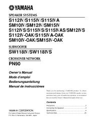
2.4.1 Checking the Two User-Serviceable Fuses<br />
The fuse rating for the user‐serviceable fuses is:<br />
T 5A L (time‐lag, 5 amp, 250 V, 20 mm, low breaking) for all operating voltages.<br />
Warning: Before performing the following steps, be sure to disconnect the DMA8Plus<br />
power cable from the power source.<br />
1. Open the DMA8Plus lid.<br />
2. Remove the fuse cover, which covers the fuses.<br />
3. Remove the two fuses from their slots, check each of them, and replace, if required.<br />
4. Replace the fuse cover.<br />
Figure 2‐1<br />
Figure 2-1<br />
Checking the User-Serviceable Fuses<br />
10 Dolby ® DMA8Plus Digital Media Adapter Installation and User’s Manual
Mains Power Wiring<br />
2.5 Mains Power Wiring<br />
In some countries the primary mains cable may not have a connector fitted. These<br />
nonterminated leads must be properly wired to an approved mains connector in<br />
accordance with the following international code:<br />
• Brown wire: Live or hot<br />
• Blue wire: Neutral<br />
• Green wire: Mains ground<br />
Warning: If you are uncertain about the wiring of your AC mains outlet then do not use it.<br />
Consult a qualified electrician.<br />
2.6 Wiring Diagrams<br />
This section contains connection diagrams for these cinema processors.<br />
• CP650<br />
• CP500<br />
• CP65/DA20<br />
• CP55/DA20<br />
• CP45/DA20<br />
• CP200/DA20<br />
Choose the appropriate diagram based on your installed equipment.<br />
Dolby ® DMA8Plus Digital Media Adapter Installation and User’s Manual 11
PROFESSIONAL AUDIO<br />
EQUIPMENT 4J06<br />
AUDIO / VIDEO APPARATUS<br />
19NJ<br />
{<br />
Installation and Maintenance<br />
Wiring Diagrams<br />
~<br />
100 - 240 Vac 50 - 60 Hz 120 W<br />
CAUTION<br />
To reduce the risk of fire<br />
replace only with same<br />
type and rating<br />
250V time-lag fuse.<br />
FUSE T 6.3A L<br />
5mmx20mm<br />
C<br />
UL<br />
LISTED<br />
US<br />
MUTE<br />
U2<br />
NONSYNC<br />
U1<br />
11<br />
10<br />
AUTOMATION<br />
REMOTES AND AUD. FADER<br />
+<br />
REMOTE DATA<br />
FADER<br />
IN<br />
N/C<br />
H/I OUTPUT<br />
This device complies with Part 15 of the FCC Rules.<br />
Operation is subject to the following two conditions: (1) this<br />
device may not cause harmful interference, and (2) this<br />
device must accept any interference received, including<br />
interference that may cause undesired operation.<br />
This Class A digital apparatus complies with Canadian ICES003.<br />
13<br />
1<br />
1<br />
01<br />
04<br />
05<br />
O<br />
14 17 20 23 24 25<br />
San Francisco U.S.<br />
READER 1<br />
READER 2<br />
L<br />
L +<br />
C<br />
C +<br />
R<br />
R +<br />
Ls<br />
Ls +<br />
Rs<br />
Rs +<br />
SW<br />
SW +<br />
13<br />
MAIN AUDIO OUTPUT<br />
CP650<br />
Digital Cinema Processor<br />
Wootton Bassett U.K.<br />
L<br />
L<br />
Dolby Digital<br />
NONSYNC IN 1<br />
R<br />
NONSYNC IN 2<br />
R<br />
SERIAL DATA (RS-232)<br />
MOTOR START<br />
WARNING<br />
Risk of electric shock.<br />
Do not open.<br />
No user serviceable parts<br />
inside. Refer all service<br />
to qualified personnel.<br />
This equipment must be<br />
earthed/grounded.<br />
6-CH AUDIO INPUT<br />
(External Digital Processor)<br />
MS1<br />
P1<br />
P1/ P2<br />
P2<br />
MS2<br />
ETHERNET<br />
OPTION CARD I/O<br />
MIC. INPUT<br />
OPTICAL IN 1<br />
R<br />
R<br />
L<br />
L<br />
OPTICAL IN 2<br />
Notes:<br />
1. Follow all local electrical and building codes.<br />
2. Use earthed (grounded) conduit wherever<br />
possible. Avoid routing signal wiring near electric<br />
motors, rectifiers, power wiring, dimmer wiring, or<br />
other sources of electrical noise.<br />
3. For two-conductor with shield wiring, use<br />
Belden 8451 two-conductor shielded cable or<br />
equivalent: tinned copper, twisted pair, 22AWG<br />
stranded tinned copper drain wire, aluminumpolyester<br />
shield, 100 percent shield coverage,<br />
conductor to conductor (111 pF per meter).<br />
From<br />
Automation<br />
Shielded<br />
Automation Cable F-M-F<br />
Dolby Part Number 83457<br />
Part of CDMA/D<br />
See Note 5.<br />
Shielded <strong>Audio</strong> Cable<br />
Dolby Part Number 83528<br />
Part of CDMA/D<br />
See Note 5.<br />
Digital Media<br />
Push Button<br />
or<br />
Relay Contacts<br />
(See Digital Media<br />
Automation<br />
Wiring Diagram)<br />
4. All shields must be connected to the chassis of<br />
the CP650 or DMA8Plus rather than to circuit<br />
(audio) ground. This achieves the RF interference<br />
immunity required by the FCC and European EMC<br />
standards. For D-connectors, a metal housing<br />
must be used and the shields must be connected<br />
to the housing.<br />
5. The Shielded <strong>Audio</strong> and Automation Cables are<br />
included in the CDMA/D cable set.<br />
Digital 4<br />
Push Button<br />
or<br />
Relay Contacts<br />
DIGITAL MEDIA<br />
AUTOMATION<br />
5<br />
8<br />
5<br />
9<br />
6<br />
1<br />
4xAES Source<br />
Eight-Channel PCM<br />
from Server<br />
F91805G_3.CDR<br />
~<br />
100–240 Vac 50–60Hz 15W<br />
Dolby, Pro Logic and the double-D symbol<br />
are registered trademarks of Dolby Laboratories.<br />
TO CP CONTROL<br />
TO DA CONTROL<br />
4XAES Digital <strong>Audio</strong> Cable<br />
Dolby Part Number 8305580<br />
DSP100 TO DMA8PLUS<br />
Digital Media Adapter<br />
DMA8Plus<br />
4xAES IN<br />
DIGITAL 1 IN<br />
This cable is included in the Cat. No. 899-DMA8<br />
Digital Cinema Installation Kit<br />
1xAES<br />
DIGITAL 2 IN<br />
1xAES<br />
OPTICAL<br />
DIGITAL 3 IN DIGITAL 4 IN<br />
DIGITAL MEDIA<br />
AUTOMATION<br />
RS-232<br />
ACT<br />
10BASE-T<br />
{<br />
LINK<br />
AUDIO OUT TO CP<br />
ANALOG AUDIO IN<br />
Auditorium<br />
Network<br />
PCM<br />
Dolby Digital (AC-3)<br />
Dolby E<br />
Digital 3<br />
Digital 2<br />
Film<br />
Digital 1<br />
DIGITAL MEDIA AUTOMATION<br />
WIRING DIAGRAM<br />
5<br />
4<br />
5<br />
3<br />
5<br />
2<br />
5<br />
1<br />
DMA8PLUS TO CP650<br />
INSTALLATION WIRING<br />
12 Dolby ® DMA8Plus Digital Media Adapter Installation and User’s Manual
AUDIO / VIDEO APPARATUS<br />
19NJ<br />
{<br />
To reduce the risk o fire<br />
replace only with same<br />
type and rating<br />
250V time-lag fuse.<br />
Installation and Maintenance<br />
Wiring Diagrams<br />
READER 1<br />
READER 2<br />
DIGITAL ACC.<br />
(Accessory I/O Only)<br />
MIC. INPUT<br />
RTA<br />
PA<br />
PA<br />
N/C<br />
ANALOG ACC. / MAG.<br />
OPTICAL 1<br />
R+<br />
L–<br />
R–<br />
L+<br />
OPTICAL 2<br />
Notes:<br />
1. Follow all local electrical and building codes.<br />
2. Use earthed (grounded) conduit wherever<br />
possible. Avoid routing signal wiring near electric<br />
motors, rectifiers, power wiring, dimmer wiring, or<br />
other sources of electrical noise.<br />
MODEL CP500<br />
CAUTION<br />
FUSE T 2A<br />
5mm x 20mm<br />
100 - 240 Vac 50 - 60 Hz 120 W<br />
6 CHANNEL INPUT<br />
(External Digital Processor)<br />
MUX PWR<br />
MUX GND<br />
MUX DATA<br />
1<br />
15-24V AC/DC IN<br />
2<br />
3<br />
4 DATA REMOTE<br />
5<br />
6 VREF<br />
FADER<br />
7 RTN<br />
8 N/C<br />
NONSYNC 1<br />
L R<br />
NONSYNC 2<br />
L R<br />
3. For two-conductor with shield wiring, use<br />
Belden 8451 two-conductor shielded cable or<br />
equivalent: tinned copper, twisted pair, 22AWG<br />
stranded tinned copper drain wire, aluminumpolyester<br />
shield, 100 percent shield coverage,<br />
conductor to conductor (111 pF per meter).<br />
From<br />
Automation<br />
4xAES Source<br />
Eight-Channel PCM<br />
from Server<br />
F91805A_3.CDR<br />
AUTOMATION<br />
SERIAL DATA<br />
Shielded<br />
Automation Cable F-M-F<br />
Dolby Part Number 83457<br />
Part of CDMA/D<br />
See Note 5.<br />
~<br />
100–240 Vac 50–60Hz 15W<br />
Dolby, Pro Logic and the double-D symbol<br />
are registered trademarks of Dolby Laboratories.<br />
MOTOR START<br />
TO CP CONTROL<br />
TO DA CONTROL<br />
Shielded<br />
4XAES Digital <strong>Audio</strong> Cable<br />
Dolby Part Number 8305580<br />
DSP100 TO DMA8PLUS<br />
BYPASS PWR / REMOTES<br />
1 2 5 6 7 8<br />
Shielded <strong>Audio</strong> Cable<br />
Dolby Part Number 83528<br />
Part of CDMA/D<br />
See Note 5.<br />
Digital Media<br />
Push Button<br />
or<br />
Relay Contacts<br />
(See Digital Media<br />
Automation<br />
Wiring Diagram)<br />
Digital Media Adapter<br />
DMA8Plus<br />
4xAES IN<br />
DIGITAL 1 IN<br />
This cable is included in the Cat. No. 899-DMA8<br />
Digital Cinema Installation Kit<br />
1xAES<br />
DIGITAL 2 IN<br />
L<br />
1xAES<br />
DIGITAL 3 IN<br />
R<br />
OPTICAL<br />
DIGITAL 4 IN<br />
Ls Rs SW<br />
HI<br />
DIGITAL MEDIA<br />
AUTOMATION<br />
RS-232<br />
Ms<br />
ACT<br />
X-OVER OUT<br />
HF<br />
BASS<br />
L R C Ls Rs<br />
10BASE-T<br />
{<br />
LINK<br />
AUDIO OUT TO CP<br />
ANALOG AUDIO IN<br />
Auditorium<br />
Network<br />
PCM<br />
Dolby Digital (AC-3)<br />
Dolby E<br />
4. All shields must be connected to the chassis of<br />
the CP500 or DMA8Plus rather than to circuit<br />
(audio) ground. This achieves the RF interference<br />
immunity required by the FCC and European EMC<br />
standards. For D-connectors, a metal housing<br />
must be used and the shields must be connected<br />
to the housing.<br />
5. The Shielded <strong>Audio</strong> and Automation Cables are<br />
included in the CDMA/D cable set.<br />
Digital 4<br />
Digital 3<br />
Digital 2<br />
Film<br />
Digital 1<br />
Push Button<br />
or<br />
Relay Contacts<br />
DIGITAL MEDIA<br />
AUTOMATION<br />
5<br />
8<br />
5<br />
4<br />
5<br />
3<br />
5<br />
2<br />
5<br />
1<br />
DIGITAL MEDIA AUTOMATION<br />
WIRING DIAGRAM<br />
5<br />
9<br />
6<br />
1<br />
DMA8PLUS TO CP500<br />
INSTALLATION WIRING<br />
Dolby ® DMA8Plus Digital Media Adapter Installation and User’s Manual 13
AUDIO / VIDEO APPARATUS<br />
19NJ<br />
{<br />
Installation and Maintenance<br />
Wiring Diagrams<br />
Notes:<br />
<strong>Audio</strong> Out<br />
to CP<br />
<strong>Audio</strong> In<br />
from CP<br />
J8<br />
J7<br />
CP Sense/<br />
J6<br />
Control<br />
Serial<br />
J3<br />
Data<br />
MODEL DA20<br />
DIGITAL FILM<br />
SOUND PROCESSOR<br />
To reduce the risk of fire<br />
or electric shock do not<br />
expose this equipment to<br />
rain or moisture.<br />
No user serviceable parts<br />
inside. Refer all service<br />
to qualified personnel.<br />
Motor<br />
Start<br />
Dolby and the double-D symbol are trademarks of Dolby Laboratories Licensing Corporation.<br />
U.S. and worldwide patents pending.<br />
J9<br />
WARNING<br />
mag format<br />
NO NR<br />
NR<br />
J24<br />
non-sync in<br />
TB1<br />
Dolby Part Number<br />
83135 (Part of CDA/65)<br />
See Note 5.<br />
L<br />
R<br />
automation inputs<br />
S0 S1 S2 S3 S4 S5 S6<br />
S7<br />
C<br />
/ O<br />
MODEL CP65<br />
M UT<br />
E<br />
Shielded <strong>Audio</strong> Cable<br />
Dolby Part Number 83528<br />
Part of CDMA/A<br />
See Note 5.<br />
auto c/o remote fader pre-amp<br />
C/ O C E B A D<br />
Lt Rt<br />
TB2<br />
1. Follow all local electrical and building codes.<br />
2. Use earthed (grounded) conduit wherever<br />
possible. Avoid routing signal wiring near electric<br />
motors, rectifiers, power wiring, dimmer wiring or<br />
other sources of electrical noise.<br />
3. For two-conductor with shield wiring, use<br />
Belden 8451 two-conductor shielded cable or<br />
equivalent: tinned copper, twisted pair, 22AWG<br />
stranded tinned copper drain wire, aluminumpolyester<br />
shield, 100 percent shield coverage,<br />
conductor to conductor (111 pF per meter).<br />
4. All shields must be connected to the chassis of<br />
the DA20 or DMA8Plus rather than to circuit<br />
(audio) ground. This achieves the RF interference<br />
immunity required by the FCC and European EMC<br />
standards. For D-connectors, a metal housing<br />
must be used and the shields must be connected<br />
to the housing.<br />
5. Re-attach existing cables (Dolby Part Numbers<br />
83134 and 83135) to the DMA8Plus as shown<br />
(cables are included in CDA/65 cable set). The<br />
Shielded <strong>Audio</strong> and Data Cables are included in<br />
CDMA/A cable set (Dolby Part Numbers 83442<br />
and 83528).<br />
Shielded Data Cable<br />
Dolby Part Number 83442<br />
Part of CDMA/A<br />
See Note 5.<br />
4xAES Source<br />
Eight-Channel PCM<br />
from Server<br />
F91805B_3.CDR<br />
~<br />
100–240 Vac 50–60Hz 15W<br />
Dolby, Pro Logic and the double-D symbol<br />
are registered trademarks of Dolby Laboratories.<br />
H/I<br />
TB3<br />
L<br />
TO CP CONTROL<br />
TO DA CONTROL<br />
4XAES Digital <strong>Audio</strong> Cable<br />
Dolby Part Number 8305580<br />
DSP100 TO DMA8PLUS<br />
MAG<br />
HEADER<br />
#2<br />
To Power Amps<br />
From mpu Format 42 From Digital Proj 1<br />
C R Ls Rs S<br />
R S Le Re L C R Ls Rs<br />
L<br />
W L C S W<br />
TB4<br />
Digital Media<br />
Push Button<br />
or<br />
Relay Contacts<br />
(See Digital Media<br />
Automation<br />
Wiring Diagram)<br />
Digital Media Adapter<br />
DMA8Plus<br />
4xAES IN<br />
DIGITAL 1 IN<br />
This cable is included in the Cat. No. 899-DMA8<br />
Digital Cinema Installation Kit<br />
1xAES<br />
DIGITAL 2 IN<br />
1xAES<br />
DIGITAL 3 IN<br />
OPTICAL<br />
DIGITAL 4 IN<br />
R<br />
TB7<br />
Proj<br />
2<br />
Proj 2<br />
Dolby Part Number 83134<br />
(Part of CDA/65) See Note 5.<br />
DIGITAL MEDIA<br />
AUTOMATION<br />
RS-232<br />
ACT<br />
10BASE-T<br />
{<br />
LINK<br />
L<br />
Cat. No. 757<br />
R<br />
AUDIO OUT TO CP<br />
ANALOG AUDIO IN<br />
Auditorium<br />
Network<br />
PCM<br />
Dolby Digital (AC-3)<br />
Dolby E<br />
6. Caution: Be sure to ground the negative side of<br />
all audio channels. The original CP audio cables<br />
were designed for unbalanced audio. Not all<br />
grounds are connected to the negative side of the<br />
associated DMA8Plus channel. Insert the Cat. No.<br />
757 audio adapter as shown on the diagram.<br />
Digital 4<br />
Digital 3<br />
Digital 2<br />
Film<br />
Digital 1<br />
Push Button<br />
or<br />
Relay Contacts<br />
DIGITAL MEDIA<br />
AUTOMATION<br />
DIGITAL MEDIA AUTOMATION<br />
WIRING DIAGRAM<br />
DMA8PLUS TO CP65/DA20<br />
INSTALLATION WIRING<br />
5<br />
8<br />
5<br />
4<br />
5<br />
3<br />
5<br />
2<br />
5<br />
1<br />
5<br />
9<br />
6<br />
1<br />
14 Dolby ® DMA8Plus Digital Media Adapter Installation and User’s Manual
AUDIO / VIDEO APPARATUS<br />
19NJ<br />
{<br />
Installation and Maintenance<br />
Wiring Diagrams<br />
<strong>Audio</strong> Out<br />
to CP<br />
<strong>Audio</strong> In<br />
from CP<br />
J8<br />
J7<br />
CP Sense/<br />
J6<br />
Control<br />
Serial<br />
J3<br />
Data<br />
MODEL DA20<br />
DIGITAL FILM<br />
SOUND PROCESSOR<br />
To reduce the risk of fire<br />
or electric shock do not<br />
expose this equipment to<br />
rain or moisture.<br />
No user serviceable parts<br />
inside. Refer all service<br />
to qualified personnel.<br />
Motor<br />
Start<br />
Dolby and the double-D symbol are trademarks of Dolby Laboratories Licensing Corporation.<br />
U.S. and worldwide patents pending.<br />
Voltage select<br />
Shielded Data Cable<br />
Dolby Part Number 83442<br />
Part of CDMA/A<br />
See Note 5.<br />
gnd<br />
TB1<br />
MODEL CP55<br />
ID7<br />
ID6<br />
ID5<br />
J9<br />
ID4<br />
WARNING<br />
ID3<br />
ID2<br />
ID1<br />
S8<br />
S2<br />
S3<br />
S4<br />
S5<br />
S6<br />
S7<br />
ID0<br />
mute<br />
gnd<br />
S9<br />
SO<br />
S1<br />
TB2<br />
remote fader<br />
indicator<br />
To DMA8<br />
AUDIO OUT TO CP<br />
CAT<br />
242<br />
28 FF<br />
1<br />
J7<br />
TB3<br />
bypass<br />
A indicator<br />
from mag aux non sync<br />
1 2<br />
C<br />
CAT.NO.<br />
241<br />
16 T<br />
1<br />
R<br />
J8<br />
S<br />
D<br />
R<br />
A<br />
L<br />
C<br />
R<br />
S<br />
CAT.NO.<br />
64B<br />
J9<br />
to power amps<br />
L C R S<br />
L<br />
R<br />
B/E<br />
Dolby Part Number 83132<br />
(Part of CDA/55) See Note 5.<br />
TB1<br />
CAT.NO.<br />
64B<br />
J10<br />
auto c/o<br />
C<br />
auto fader<br />
/ O C E B A D FI BC Lt Rt<br />
CAT.NO.<br />
64B<br />
test<br />
J18<br />
J11<br />
bypass<br />
preamp<br />
TB2<br />
CAT.NO. CAT.NO. CAT.NO.<br />
150 85 222<br />
Dolby Part Number 83133<br />
(Part of CDA/55) See Note 5.<br />
Digital Media<br />
Push Button<br />
or<br />
Relay Contacts<br />
(See Digital Media<br />
Automation<br />
Wiring Diagram)<br />
J12<br />
TB4<br />
J13<br />
J14<br />
Proj 1<br />
Shielded <strong>Audio</strong> Cable<br />
Dolby Part Number 83528<br />
Part of CDMA/A<br />
See Note 5.<br />
CAT.NO.<br />
240 spare<br />
J15<br />
Proj 2<br />
L R L R<br />
Cat. No. 757<br />
J16<br />
Notes:<br />
1. Follow all local electrical and building codes.<br />
2. Use earthed (grounded) conduit wherever<br />
possible. Avoid routing signal wiring near electric<br />
motors, rectifiers, power wiring, dimmer wiring, or<br />
other sources of electrical noise.<br />
3. For two-conductor with shield wiring, use<br />
Belden 8451 two-conductor shielded cable or<br />
equivalent: tinned copper, twisted pair, 22AWG<br />
stranded tinned copper drain wire, aluminumpolyester<br />
shield, 100 percent shield coverage,<br />
conductor to conductor (111 pF per meter).<br />
4. All shields must be connected to the chassis of<br />
the DA20 or DMA8Plus rather than to circuit<br />
(audio) ground. This achieves the RF interference<br />
immunity required by the FCC and European EMC<br />
standards. For D-connectors, a metal housing<br />
must be used and the shields must be connected<br />
to the housing.<br />
5. Re-attach existing cables (Dolby Part Numbers<br />
83132 and 83133) to the DMA8Plus as shown.<br />
(Cables are included in CDA/55 cable set.) The<br />
Shielded <strong>Audio</strong> and Data Cables are included in<br />
CDMA/A cable set (Dolby Part Numbers 83442<br />
and 83528).<br />
6. Caution: Be sure to ground the negative side of<br />
all audio channels. The original CP audio cables<br />
were designed for unbalanced audio. Not all<br />
grounds are connected to the negative side of the<br />
associated DMA8Plus channel. Insert the Cat. No.<br />
757 audio adapter as shown on the diagram.<br />
Digital 4<br />
Digital 3<br />
Push Button<br />
or<br />
Relay Contacts<br />
DIGITAL MEDIA<br />
AUTOMATION<br />
5<br />
8<br />
5<br />
4<br />
5<br />
9<br />
6<br />
1<br />
4xAES Source<br />
Eight-Channel PCM<br />
from Server<br />
F91805D_3.CDR<br />
~<br />
100–240 Vac 50–60Hz 15W<br />
Dolby, Pro Logic and the double-D symbol<br />
are registered trademarks of Dolby Laboratories.<br />
TO CP CONTROL<br />
TO DA CONTROL<br />
4XAES Digital <strong>Audio</strong> Cable<br />
Dolby Part Number 8305580<br />
DSP100 TO DMA8PLUS<br />
Digital Media Adapter<br />
DMA8Plus<br />
4xAES IN<br />
DIGITAL 1 IN<br />
This cable is included in the Cat. No. 899-DMA8<br />
Digital Cinema Installation Kit<br />
1xAES<br />
DIGITAL 2 IN<br />
1xAES<br />
OPTICAL<br />
DIGITAL 3 IN DIGITAL 4 IN<br />
DIGITAL MEDIA<br />
AUTOMATION<br />
RS-232<br />
ACT<br />
10BASE-T<br />
{<br />
LINK<br />
AUDIO OUT TO CP<br />
ANALOG AUDIO IN<br />
Auditorium<br />
Network<br />
PCM<br />
Dolby Digital (AC-3)<br />
Dolby E<br />
Digital 2<br />
Film<br />
Digital 1<br />
DIGITAL MEDIA AUTOMATION<br />
WIRING DIAGRAM<br />
DMA8PLUS TO CP55/DA20<br />
INSTALLATION WIRING<br />
5<br />
3<br />
5<br />
2<br />
5<br />
1<br />
Dolby ® DMA8Plus Digital Media Adapter Installation and User’s Manual 15
AUDIO / VIDEO APPARATUS<br />
19NJ<br />
L<br />
{<br />
L<br />
Installation and Maintenance<br />
Wiring Diagrams<br />
<strong>Audio</strong> Out<br />
to CP<br />
<strong>Audio</strong> In<br />
from CP<br />
J8<br />
J7<br />
CP Sense/<br />
J6<br />
Control<br />
Serial<br />
J3<br />
Data<br />
1 2 3 4<br />
NORMAL<br />
J1<br />
MODEL DA20<br />
DIGITAL FILM<br />
SOUND PROCESSOR<br />
BYPASS<br />
J2<br />
LF<br />
HF<br />
1 2 3 4 5 6 7 8<br />
LF HF LF HF<br />
FULL<br />
RANGE<br />
LEFT<br />
*<br />
LF<br />
To reduce the risk of fire<br />
or electric shock do not<br />
expose this equipment to<br />
rain or moisture.<br />
No user serviceable parts<br />
inside. Refer all service<br />
to qualified personnel.<br />
Dolby and the double-D symbol are trademarks of Dolby Laboratories Licensing Corporation.<br />
U.S. and worldwide patents pending.<br />
J9<br />
J9<br />
BOOTH MONITOR OUTPUT<br />
HF<br />
FULL<br />
RANGE<br />
CENTER<br />
WARNING<br />
Motor<br />
Start<br />
J3<br />
LF<br />
1 2 3 4 5 6<br />
LF<br />
HF<br />
HF<br />
OUTPUTS<br />
LS<br />
Ls<br />
RS<br />
7 8<br />
Rs<br />
RANGE<br />
SW<br />
1 2 3 4 5 6 7 8<br />
SW<br />
HEARING<br />
IMPAIRED<br />
J4<br />
MODEL CP45<br />
L R<br />
NON<br />
SYNC 1<br />
Dolby Part Number 83135<br />
(Part of CDA/45) See Note 5.<br />
Cat. No. 545A<br />
(Part of CDA/45)<br />
See Note 5.<br />
J5<br />
1 2 3 4 5 6 7 8<br />
C<br />
R<br />
COM<br />
S<br />
R S<br />
SW<br />
COM<br />
NON-SYNC 2<br />
AUXILIARY<br />
TO AUTOMATION<br />
J11<br />
INPUTS<br />
TO CPU P10<br />
J6<br />
1 2 3 4 5 6 7<br />
8<br />
COM<br />
P2<br />
P1<br />
PROJECTOR<br />
MIC CHANGEOVER<br />
Shielded <strong>Audio</strong> Cable<br />
Dolby Part Number 83528<br />
Part of CDMA/A See Note 5.<br />
J10<br />
CONTROL<br />
LOGIC TO<br />
DIGITAL<br />
PROCESSOR<br />
J12<br />
J7<br />
PROJECTOR 1<br />
R+<br />
R–<br />
L+<br />
L–<br />
J8<br />
PROJECTOR 2<br />
Notes:<br />
1. Follow all local electrical and building codes.<br />
2. Use earthed (grounded) conduit wherever<br />
possible. Avoid routing signal wiring near electric<br />
motors, rectifiers, power wiring, dimmer wiring, or<br />
other sources of electrical noise.<br />
3. For two-conductor with shield wiring, use Belden<br />
8451 two-conductor shielded cable or equivalent:<br />
tinned copper, twisted pair, 22 AWG stranded tinned<br />
copper drain wire, aluminum-polyester shield, 100<br />
percent shield coverage, conductor to conductor<br />
(111 pF per meter).<br />
4. All shields must be connected to the chassis of<br />
the DA20 or DMA8Plus rather than to circuit (audio)<br />
ground. This achieves the RF interference immunity<br />
required by the FCC and European EMC standards.<br />
For D-connectors, a metal housing must be used<br />
and the shields must be connected to the housing.<br />
5. Re-attach existing cables (Dolby Part Numbers<br />
83306 and 83135) to the DMA8Plus as shown.<br />
(Cables and Cat. No. 545A are included in CDA/45<br />
upgrade kit. All existing Cat. No. 545 assemblies<br />
must be upgraded to Cat. No. 545A. The Shielded<br />
<strong>Audio</strong> and Data Cables are included in CDMA/A<br />
cable set (Dolby Part Numbers 83442 and 83528).<br />
Shielded Data Cable<br />
Dolby Part Number 83442<br />
Part of CDMA/A<br />
See Note 5.<br />
4xAES Source<br />
Eight-Channel PCM<br />
from Server<br />
F91805C_3.CDR<br />
~<br />
100–240 Vac 50–60Hz 15W<br />
Dolby, Pro Logic and the double-D symbol<br />
are registered trademarks of Dolby Laboratories.<br />
TO CP CONTROL<br />
TO DA CONTROL<br />
4XAES Digital <strong>Audio</strong> Cable<br />
Dolby Part Number 8305580<br />
DSP100 TO DMA8PLUS<br />
Digital Media Adapter<br />
This cable is included in the Cat. No. 899-DMA8<br />
Digital Cinema Installation Kit<br />
Digital Media<br />
Push Button<br />
or<br />
Relay Contacts<br />
(See Digital Media<br />
Automation<br />
Wiring Diagram)<br />
DMA8Plus<br />
4xAES IN<br />
DIGITAL 1 IN<br />
1 2 3 4 5 6 7 8<br />
1xAES<br />
DIGITAL 2 IN<br />
1xAES<br />
DIGITAL 3 IN<br />
Dolby Part Number 83306<br />
(Part of CDA/45) See Note 5&6.<br />
OPTICAL<br />
DIGITAL 4 IN<br />
DIGITAL MEDIA<br />
AUTOMATION<br />
RS-232<br />
ACT<br />
Cat. No. 757<br />
10BASE-T<br />
{<br />
LINK<br />
AUDIO OUT TO CP<br />
ANALOG AUDIO IN<br />
Auditorium<br />
Network<br />
PCM<br />
Dolby Digital (AC-3)<br />
Dolby E<br />
6. Caution: Be sure to ground the negative side of<br />
all audio channels. The original CP audio cables<br />
were designed for unbalanced audio. Not all<br />
grounds are connected to the negative side of the<br />
associated DMA8Plus channel. Insert the Cat. No.<br />
757 audio adapter as shown on the diagram.<br />
Digital 4<br />
Digital 3<br />
Digital 2<br />
Film<br />
Digital 1<br />
Push Button<br />
or<br />
Relay Contacts<br />
DIGITAL MEDIA<br />
AUTOMATION<br />
DIGITAL MEDIA AUTOMATION<br />
WIRING DIAGRAM<br />
DMA8PLUS TO CP45/DA20<br />
INSTALLATION WIRING<br />
5<br />
8<br />
5<br />
4<br />
5<br />
3<br />
5<br />
2<br />
5<br />
1<br />
5<br />
9<br />
6<br />
1<br />
16 Dolby ® DMA8Plus Digital Media Adapter Installation and User’s Manual
AUDIO / VIDEO APPARATUS<br />
19NJ<br />
{<br />
Installation and Maintenance<br />
Wiring Diagrams<br />
<strong>Audio</strong> Out<br />
J8<br />
to CP<br />
<strong>Audio</strong> In<br />
from CP<br />
J7<br />
CP Sense/<br />
J6<br />
Control<br />
Serial<br />
J3<br />
Data<br />
MODEL DA20<br />
DIGITAL FILM<br />
SOUND PROCESSOR<br />
To reduce the risk of fire<br />
or electric shock do not<br />
expose this equipment to<br />
rain or moisture.<br />
No user serviceable parts<br />
inside. Refer all service<br />
to qualified personnel.<br />
Motor<br />
Start<br />
Dolby and the double-D symbol are trademarks of Dolby Laboratories Licensing Corporation.<br />
U.S. and worldwide patents pending.<br />
J9<br />
WARNING<br />
Dolby Part Number<br />
83136<br />
Part of CDA/200<br />
.<br />
Shielded <strong>Audio</strong> Cable<br />
Dolby Part Number<br />
83528<br />
Part of CDMA/A<br />
See Note 5.<br />
Dolby Part Number<br />
83137<br />
Part of CDA/200<br />
See Note 5.<br />
Dolby Part Number<br />
83138<br />
Part of CDA/200<br />
See Note 5.<br />
JM20<br />
JM2<br />
SP2-14<br />
JM11<br />
JM21<br />
Digital Media Adapter<br />
JM3<br />
DMA8Plus<br />
BS24<br />
(1)<br />
JM10<br />
PJ24<br />
BS1<br />
JM4<br />
JM9<br />
JM22<br />
PJ23<br />
SK13<br />
SP2 CAT.150 CAT.160<br />
16 T<br />
1<br />
A<br />
1 1<br />
PJ22<br />
Digital Media<br />
Push Button or<br />
Relay Contacts<br />
(See Digital Media<br />
Automation Wiring Diagram)<br />
A<br />
B<br />
23<br />
(12)<br />
PJ21<br />
SK13-B21<br />
PROJ 1<br />
JM24<br />
JM23<br />
(1) BS2 (12)<br />
RL3<br />
CP200 Processor Unit<br />
SK13-B1<br />
EMERGENCY C/O<br />
PROJ 2<br />
PROJ 1 CONTROL<br />
PROJ 2 CONTROL<br />
PROJ 3 CONTROL<br />
AUTO MUTE<br />
MUTE LED<br />
JM26<br />
JM25<br />
JM30<br />
(1) BS23<br />
(12) (1) BS22<br />
(12)<br />
Cat. No. 757<br />
JM8<br />
RL2<br />
JM5<br />
(1)<br />
(1)<br />
CP200 Control Unit<br />
Notes:<br />
1. Follow all local electrical and building codes.<br />
2. Use earthed (grounded) conduit wherever<br />
possible. Avoid routing signal wiring near electric<br />
motors, rectifiers, power wiring, dimmer wiring, or<br />
other sources of electrical noise.<br />
3. For two-conductor with shield wiring, use Belden<br />
8451 two-conductor shielded cable or equivalent:<br />
tinned copper, twisted pair, 22 AWG stranded tinned<br />
copper drain wire, aluminum-polyester shield, 100<br />
percent shield coverage, conductor to conductor<br />
(111 pF per meter).<br />
4. All shields must be connected to the chassis of<br />
the DA20 or DMA8Plus rather than to circuit (audio)<br />
ground. This achieves the RF interference immunity<br />
required by the FCC and European EMC standards.<br />
For D-connectors, a metal housing must be used<br />
and the shields must be connected to the housing.<br />
5. Re-attach existing cables (Dolby Part No’s 83137<br />
and 83138) to the DMA8Plus as shown. (Cables<br />
included in CDA/200 cable set.) The Shielded <strong>Audio</strong><br />
Cable is included in the CDMA/A cable set.<br />
Digital 4<br />
Digital 3<br />
Digital 2<br />
Film<br />
Digital 1<br />
Push Button or<br />
Relay Contacts<br />
<strong>Audio</strong><br />
5<br />
8<br />
5<br />
4<br />
5<br />
3<br />
5<br />
2<br />
5<br />
1<br />
5<br />
9<br />
CP200 PU<br />
DA20<br />
6<br />
1<br />
DIGITAL MEDIA<br />
AUTOMATION<br />
CP200 PU<br />
Digital<br />
Subwoofer<br />
Control<br />
DIGITAL MEDIA AUTOMATION<br />
WIRING DIAGRAM<br />
6<br />
7<br />
SK13-B21<br />
GND<br />
Control<br />
4xAES Source<br />
Eight-Channel PCM<br />
from Server<br />
F91805E_3.CDR<br />
~<br />
100–240 Vac 50–60Hz 15W<br />
Dolby, Pro Logic and the double-D symbol<br />
are registered trademarks of Dolby Laboratories.<br />
TO CP CONTROL<br />
TO DA CONTROL<br />
4XAES Digital <strong>Audio</strong> Cable<br />
Dolby Part Number 8305580<br />
DSP100 TO DMA8PLUS<br />
4xAES IN<br />
DIGITAL 1 IN<br />
This cable is included in the Cat. No. 899-DMA8<br />
Digital Cinema Installation Kit<br />
1xAES<br />
DIGITAL 2 IN<br />
1xAES<br />
OPTICAL<br />
DIGITAL 3 IN DIGITAL 4 IN<br />
DIGITAL MEDIA<br />
AUTOMATION<br />
RS-232<br />
ACT<br />
10BASE-T<br />
{<br />
LINK<br />
AUDIO OUT TO CP<br />
ANALOG AUDIO IN<br />
Auditorium<br />
Network<br />
PCM<br />
Dolby Digital (AC-3)<br />
Dolby E<br />
DMA8PLUS<br />
CP200 CU<br />
SIGNAL FLOW DIAGRAM<br />
DMA8PLUS TO CP200/DA20<br />
INSTALLATION WIRING<br />
Dolby ® DMA8Plus Digital Media Adapter Installation and User’s Manual 17
Chapter 3<br />
Setting Up the DMA8Plus<br />
3.1 DMA8Plus Setup Software<br />
The setup software is required to complete the DMA8Plus installation and perform other<br />
functions. You begin by installing the setup software on a PC running Microsoft ®<br />
Windows ® XP (Service Pack 2 or later) or Windows Vista ® (setup software version 1.2.10.2<br />
or later). When the installation is completed, you launch the setup software, and then<br />
connect your PC to the DMA8Plus using a USB cable (as described in Installing and<br />
Running the Setup Software on page 20). You can then use the setup software to perform<br />
the following functions:<br />
• Select the model number of the cinema processor connected to the DMA8Plus for<br />
DA/CP control<br />
• Enter the network settings<br />
• Select the PCM input‐channel routing (PCM Channel Assignment)<br />
• Set the Global delay for each digital input<br />
• Set the AES 1/2 Decode Mode and 2Ch Decode Mode (Pro Logic ® , Pro Logic II, or<br />
Discrete L/R) for PCM<br />
• Set the 2Ch Decode Mode (Auto, Pro Logic, Pro Logic II, or Discrete L/R) for Dolby ®<br />
Digital, and Dolby E<br />
• Enable or disable the PCM Processing Mode<br />
• Enable or disable Dialog Normalization for Dolby Digital bitstreams<br />
• Set the Surround Delay<br />
• Select the Pro Logic subwoofer filter<br />
• Select the Power-on Mode<br />
• Select the ‘To CP Control’ Pin Assignments<br />
In addition, the setup software displays the following information:<br />
• Sample Rate and Data Rate (when available)<br />
• Dialnorm and Channel Mode metadata information (when available)<br />
• Signal‐level monitoring level meters<br />
• Current input selection<br />
• <strong>Audio</strong> format (PCM, Dolby Digital, Dolby E, or Aux)<br />
• Decode mode (Pro Logic, Pro Logic II, or Discrete)<br />
• Version numbers for the DMA8Plus firmware and setup software<br />
The following sections provide a detailed description of all the setup software functions.<br />
Dolby ® DMA8Plus Digital Media Adapter Installation and User’s Manual 19
Setting Up the DMA8Plus<br />
3.2 Installing and Running the Setup Software<br />
1. Run the DMA8Plus installation program to install the setup software on your PC.<br />
The welcome screen appears, as shown in Figure 3‐1.<br />
Figure 3-1<br />
Installation Welcome Screen<br />
2. Click Next, then follow the onscreen instructions to install the software.<br />
3. Launch the setup software by selecting Start>Programs>Dolby>DMA8Plus Setup, then<br />
connect your PC to the DMA8Plus front‐panel USB port to establish a connection.<br />
The DMA8Plus Profile settings window appears, as shown in Figure 3‐2.<br />
3.3 Profile<br />
When you launch and connect the DMA8Plus setup software, the Profile settings window<br />
appears, as shown in Figure 3‐2. The virtual status monitor appears in the lower section of<br />
the window.<br />
Near the top of the window, there are also tabs for Network, Digital Input 1, Digital Input 2,<br />
Digital Input 3, Digital Input 4, and General Settings. When you click any of these tabs, the<br />
corresponding parameter window appears where you can enter and/or modify the<br />
respective settings, as described in the sections that follow. The virtual status monitor also<br />
appears at the bottom of each of these tab settings windows. Following is a description of<br />
the Profile settings and the virtual status monitor.<br />
20 Dolby ® DMA8Plus Digital Media Adapter Installation and User’s Manual
Profile<br />
Figure 3-2<br />
Profile Settings Window<br />
3.3.1 Profile Settings<br />
Selecting this tab displays the Profile settings window. In this window, you can enter the<br />
corresponding information for your system. This information defines the Theatre Profile for<br />
the local auditorium. In addition, Input Descriptions appears for each digital input. You can<br />
edit each description and enter the desired information.<br />
3.3.2 Virtual Status Monitor<br />
The virtual status monitor provides a user‐friendly interface that is similar to the<br />
DMA8Plus front panel. Its eight‐channel signal‐presence meter monitors the DMA8Plus<br />
analog output (before the bypass relays). Five virtual buttons represent the digital 1, digital<br />
2, digital 3, digital 4, and film input selections. When you click any of these buttons, the<br />
associated input is activated. Each of the digital input buttons has an associated virtual<br />
LED, representing a valid clock presence. In addition, four virtual LEDs represent format<br />
decoding, one each for PCM, Dolby Digital, Dolby E, and Aux (for future use). Three more<br />
virtual LEDs represent the decode mode, one each for Pro Logic II, Pro Logic, and Discrete.<br />
Parameter indicators display the Sample Rate, Data Rate, Dialnorm, and Channel Mode<br />
(when available).<br />
Dolby ® DMA8Plus Digital Media Adapter Installation and User’s Manual 21
Setting Up the DMA8Plus<br />
3.4 Network<br />
Selecting this tab displays the DMA8Plus Ethernet Settings window, as shown in<br />
Figure 3‐3. In this window, you can configure the DMA8Plus network settings. If you<br />
change the network settings, two buttons are highlighted below your settings: Discard<br />
Changes and Apply Changes. Clicking one of these buttons performs the respective action.<br />
The default entries are set for a Dolby Digital Cinema system. Following is list of these<br />
default entries:<br />
• Host Name: DMA8Plus<br />
• DHCP: Disable<br />
• IP Address: 192.168.x.131 (x = auditorium number)<br />
• Subnet Mask: 255.255.255.128<br />
• Default Gateway: 192.168.x.129 (x = auditorium number)<br />
Figure 3‐1<br />
Figure 3-3<br />
Ethernet Settings Window<br />
22 Dolby ® DMA8Plus Digital Media Adapter Installation and User’s Manual
Digital Inputs 1, 2, 3, and 4<br />
3.5 Digital Inputs 1, 2, 3, and 4<br />
Selecting any of these tabs displays the corresponding digital input window. The examples<br />
in Figure 3‐4 and Figure 3‐5 show the Digital Input 1 and Digital Input 2 windows. The same<br />
setting options are provided in each digital input window, except for the PCM Channel<br />
Assignment and AES 1/2 Decode Mode which appear only in the Digital Input 1 window and<br />
the PCM 2Ch Decode Mode, which appears only in the Digital Input 2, 3, and 4 windows. The<br />
following sections describe each of these settings.<br />
Figure 3‐2<br />
Figure 3-4<br />
Digital Input 1 Window<br />
Dolby ® DMA8Plus Digital Media Adapter Installation and User’s Manual 23
Setting Up the DMA8Plus<br />
Figure 3‐3<br />
Figure 3-5<br />
Digital Input 2 Window<br />
3.5.1 Global Delay<br />
Specifies an audio delay (in addition to the DMA8Plus decoding delay of approximately<br />
7 ms for 4xAES PCM). This function synchronizes the audio with the video that is required<br />
for digital cinema projectors, which add a video processing delay. Use the up and down<br />
arrows to set the Global delay between 0 and 250 ms. You can specify a different Global delay<br />
for digital 1, digital 2, digital 3, and digital 4.<br />
Systems that use an external video scaler may add another decoding delay.<br />
3.5.2 PCM Settings<br />
Following is a description of the PCM settings.<br />
PCM Channel Assignment (Digital Input 1 Only)<br />
The analog audio output channels (L, R, C, LFE, Ls, Rs) are always fixed and hardwired to<br />
a cinema processor. However, when a PCM bitstream input‐channel mapping is not a<br />
default SMPTE configuration (L/R, C/LFE, Ls/Rs), you must reassign the input channels to<br />
match the hard wired audio outputs. For channel reassignment, the surround delay and<br />
the LFE filter are always tied at the output, and therefore cause no problem.<br />
24 Dolby ® DMA8Plus Digital Media Adapter Installation and User’s Manual
Digital Inputs 1, 2, 3, and 4<br />
To reassign the input channels, use the drop‐down menu for each of the AES channel<br />
inputs or click one of the three preset buttons (L/R C/Sw/ Ls/Rs, L/C R/Ls, Rs/Sw, or<br />
L/Ls C/Rs R/Sw). To activate your changes, click the Apply changes button. To cancel your<br />
changes, click the Discard changes button.<br />
AES 1/2 Decode Mode (Digital Input 1 Only)<br />
This mode applies to two‐channel PCM bitstreams on the 4 x AES IN 1/2 channel pair. There<br />
are three options: Pro Logic, Pro Logic II, and Discrete L/R. Typically, you connect this input<br />
to a digial cinema server and set it to Discrete L/R. However, if you connect this input only<br />
to a single PCM bitstream, you can set it to Pro Logic or Pro Logic II.<br />
Processing Mode<br />
Minimum Latency<br />
When selected, this default mode provides the quickest audio processing (approximately<br />
7 ms) for PCM audio.<br />
Silent Switch<br />
When selected, this mode constantly checks for transitions between PCM and coded audio,<br />
and switches between the two silently. This mode adds a 40 ms latency to the audio<br />
processing (for a total latency of approximately 47 ms).<br />
Mute<br />
When selected, this mode mutes the audio when PCM is detected.<br />
2Ch Decode Mode (Digital Inputs 2, 3, and 4 Only)<br />
This mode applies only to a two‐channel input stream. There are three options: Pro Logic,<br />
Pro Logic II, and Discrete L/R.<br />
Note:<br />
For Dolby Digital Cinema multichannel PCM, you must use the Discrete L/R option<br />
in the Digital Input 1 window.<br />
3.5.3 Dolby Digital Settings<br />
Following is a description of the Dolby Digital settings.<br />
2Ch Decode Mode<br />
For two‐channel configurations, there are four options: Auto, Pro Logic, Pro Logic II, and<br />
Discrete L/R. The audio decode mode follows the surrounds metadata parameter that is<br />
embedded within the bitstream. Alternatively, you can enable Pro Logic or Pro Logic II<br />
decoding, which overrides the presence or absence of the surrounds metadata in<br />
two‐channel bitstreams. The Discrete L/R mode sends the audio only to the Left and Right<br />
channels.<br />
Dolby ® DMA8Plus Digital Media Adapter Installation and User’s Manual 25
Setting Up the DMA8Plus<br />
Dialog Normalization<br />
When enabled (Enable), this option sets the decoder level shift according to the encoded<br />
metadata embedded in a Dolby Digital (AC‐3) bitstream. Metadata is available on most<br />
DVDs, terrestrial and satellite broadcast signals, and other Dolby Digital sources. The<br />
default is Disable.<br />
3.5.4 Dolby E Settings<br />
Following is a description of the Dolby E settings.<br />
2Ch Decode Mode<br />
Same functionality as for Dolby Digital, as described previously.<br />
Dialog Normalization<br />
Same functionality as for Dolby Digital, as described previously.<br />
Program Select<br />
You can select one of four possible programs to receive a Dolby E bitstream: P1, P2, P3, or<br />
P4. The default is P1.<br />
26 Dolby ® DMA8Plus Digital Media Adapter Installation and User’s Manual
General Settings<br />
3.6 General Settings<br />
Selecting this tab displays the General Settings window, as shown in Figure 3‐6. Following<br />
is a description of each of these settings.<br />
Figure 3‐4<br />
Figure 3-6<br />
General Settings Window<br />
3.6.1 CP Settings<br />
Following is a description of the cinema processor (CP) settings.<br />
Cinema Processor<br />
Selects the cinema processor connected to the DMA8Plus. This parameter affects the ‘To CP<br />
Control’ Pin Assignments. If you are not using a Dolby processor, select Custom and set the<br />
appropriate ‘To CP Control’ Pin Assignments for your setup.<br />
‘To CP Control’ Pin Assignments<br />
The pin assignments for Film and Digital Media correspond to the cinema processor’s<br />
nonsync format and six‐channel input format. For default CP formats on control lines 0–7<br />
(pins 1–8) see Table 4‐7. The various DMA8Plus cinema processor Film defaults correspond<br />
to each cinema processor’s default nonsync format. Likewise, the Digital Media defaults<br />
correspond to each cinema processor’s default six‐channel input format. You can change<br />
any of these pins manually to accommodate your setup.<br />
Dolby ® DMA8Plus Digital Media Adapter Installation and User’s Manual 27
Setting Up the DMA8Plus<br />
3.6.2 Surround Delay<br />
When the unit receives audio from a digital media source, you need to apply a delay to the<br />
Surround channels, so the Center and Surrounds audio reach the listener at the same time.<br />
Set the Surround Delay by entering the dimensions of the auditorium and clicking the<br />
Calculate button, or use the slider if you know the required delay setting.<br />
Note:<br />
If the DMA8Plus is connected to a CP650, the CP650 applies the appropriate digital<br />
media surround delay based on its settings (format 11). If the CP650 has been<br />
selected as the cinema processor type, the Surround Delay setting in this window is<br />
disabled. Use this function to set the digital media surround delay only when<br />
connected to other cinema processors.<br />
3.6.3 Pro Logic/Pro Logic II Subwoofer<br />
Selects a subwoofer filter of 50 Hz (default) or 100 Hz for Pro Logic and Pro Logic II<br />
decoding. This subwoofer signal is derived from the matrix decoded sum of Left, Center,<br />
and Right, which passes through this filter. The main audio outputs bandwidth (L, C, R) is<br />
not affected because this subwoofer signal is a reinforcement rather than a bass redirection.<br />
3.6.4 Power-on Mode<br />
Selects the desired DMA8Plus startup mode when the unit is powered on. You can select<br />
Last Setting, Film, or any of the digital inputs: digital 1 (4xAES), digital 2 (1xAES),<br />
digital 3 (1xAES), or digital 4 (Optical).<br />
28 Dolby ® DMA8Plus Digital Media Adapter Installation and User’s Manual
File Menu<br />
3.7 File Menu<br />
You can use the setup software File menu to load and save settings. Following is a<br />
description of each of these functions.<br />
3.7.1 Loading Settings<br />
You can load a previously saved .dlb parameter file as follows:<br />
Select Open in the File menu, browse to the desired .dlb file on your PC, and open that file.<br />
Figure 3‐5<br />
Figure 3-7<br />
Selecting Open in the File Menu<br />
3.7.2 Saving Settings<br />
You can save your <strong>current</strong> settings to a .dlb parameter file as follows:<br />
Select Save in the File menu, browse to the location on your PC where you want to save the<br />
file, enter a file name, and click Save. To modify an existing .dlb file and save it under a<br />
different name, open the file, then select Save As in the File menu.<br />
Figure 3‐6<br />
Figure 3-8<br />
Selecting Save in the File Menu<br />
Dolby ® DMA8Plus Digital Media Adapter Installation and User’s Manual 29
Setting Up the DMA8Plus<br />
3.8 Action Menu<br />
You can use the setup software Action menu to connect to a local or remote device and<br />
update the DMA8Plus firmware, as described in the sections that follow. The Extract Logs<br />
and View Log options <strong>current</strong>ly do not function. To extract an event log, see ASCII String<br />
Commands on page 42.<br />
Figure 3‐7<br />
Figure 3-9<br />
Action Menu<br />
3.8.1 Connecting to a Local or Remote Device<br />
These options allow you to connect to a DMA8Plus that is connected to your PC (local<br />
device) or a DMA8Plus that is connected to an Ethernet network (remote device). If you<br />
select Connect to remote device, a prompt for an IP address appears, as shown in<br />
Figure 3‐10. Enter the IP address of the remote DMA8Plus and click OK.<br />
Note:<br />
If you are connecting directly to a DMA8Plus, use a crossover cable. If you are<br />
connecting through an Ethernet switch, use a standard Ethernet cable.<br />
Figure 3‐8<br />
Figure 3-10 Connect to Remote DMA8Plus Prompt<br />
When connecting the setup software to a DMA8Plus using a PC Ethernet connection, you<br />
must change the PC’s TCP/IP properties to communicate properly with the DMA8Plus. We<br />
recommend the following TCP/IP settings to enable your PC to communicate with a<br />
DMA8Plus using its default setting.<br />
IP address: 192.168.1.200<br />
Subnet mask: 255.255.255.128<br />
Default gateway: 192.168.1.129<br />
Note: The DMA8Plus default IP address (for connecting) is 192.168.131.<br />
30 Dolby ® DMA8Plus Digital Media Adapter Installation and User’s Manual
Window Menu<br />
3.8.2 Update Software<br />
With setup software version 1.2.5.0 and later, when you select this option, the setup<br />
software closes and Dolby Software Update automatically opens and connects. You can<br />
then update the DMA8Plus firmware by following the directions in Updating the<br />
DMA8Plus Firmware on page 32. When the update is completed, Dolby Software Update<br />
closes and the setup software opens and reconnects.<br />
3.9 Window Menu<br />
You can use the Window menu to toggle in and out of Expert View mode. In addition, you<br />
can turn the Setup (tabs view) and/or Monitor display(s) on or off.<br />
Figure 3‐9<br />
Figure 3-11 Window Menu<br />
Using Expert View<br />
When you select Expert View, all the DMA8Plus parameters and command strings appear,<br />
including some parameters not displayed in the tabs view. You can modify each of the<br />
parameters that are highlighted in green by double clicking on any of these (or selecting<br />
one and pressing ), and then typing the new parameter entry. For more<br />
information, see ASCII String Commands on page 42. To return to the tabs display, select<br />
Expert View again to uncheck it.<br />
Figure 3‐10<br />
Figure 3-12 Expert View Window<br />
Dolby ® DMA8Plus Digital Media Adapter Installation and User’s Manual 31
Setting Up the DMA8Plus<br />
3.10 Updating the DMA8Plus Firmware<br />
To update the DMA8Plus firmware:<br />
1. Obtain the latest version of the Dolby Software Update application from Dolby<br />
Laboratories and install it on your PC.<br />
2. Obtain the .dlb update file from Dolby Laboratories and copy it to your PC.<br />
3. Connect your PC to the USB port on the DMA8Plus front panel.<br />
4. Select Start>Programs>Dolby>Dolby Software Update to launch the update application.<br />
Figure 3‐11<br />
Figure 3-13 Dolby Software Update Screen<br />
5. Click Browse to find the .dlb update file on your PC, then click Open.<br />
6. Click Update.<br />
After a few seconds, a progress bar displays the status of the update process. When the<br />
process is completed, the DMA8Plus automatically reboots with the updated<br />
firmware.<br />
Note:<br />
Current DMA8Plus setup software automatically launches the built‐in<br />
Dolby Software Update application.<br />
32 Dolby ® DMA8Plus Digital Media Adapter Installation and User’s Manual
Chapter 4<br />
Technical Reference<br />
4.1 DMA8Plus Specifications<br />
PC Connection<br />
USB port for setup operations and software upgrades<br />
Input Selector Buttons<br />
Digital 1 through 4 source buttons<br />
Film source button (pass‐through)<br />
Indicators<br />
Valid LEDs indicate digital input clock presence for each digital input<br />
Format LEDs indicate PCM, Dolby Digital, Dolby E, or Aux (future) processing<br />
Decode mode LEDs indicate Pro Logic II, Pro Logic, or Discrete modes<br />
Output activity LEDs indicate the presence of signals in each output channel<br />
Construction<br />
1‐U rackmount chassis frame<br />
Digital Signal Inputs<br />
All have floating grounds, +10 V peak difference between the DMA8Plus chassis and signal<br />
common is permitted<br />
Digital 1 In (4xAES)<br />
25‐pin female D‐connector provides four AES/EBU inputs of PCM audio (up to eight<br />
channels)<br />
Input impedence: 110 Ω<br />
Digital 2 In (1xAES)<br />
Male BNC connector, unbalanced per AES‐3ID‐1995/SMPTE 276M<br />
Input impedence: 75 Ω<br />
Digital 3 In (1xAES)<br />
Male BNC connector, unbalanced per AES‐3ID‐1995/SMPTE 276M<br />
Input impedence: 75 Ω<br />
Dolby ® DMA8Plus Digital Media Adapter Installation and User’s Manual 33
Technical Reference<br />
Digital 4 In (Optical)<br />
Optical connector for digital input<br />
Digital <strong>Audio</strong> Source Formats<br />
PCM: 44.1, 48 and 96 kHz; 16‐, 20‐, 24‐bit<br />
Dolby Digital (AC‐3)<br />
Dolby E (23.98, 24, 25, 29.97, 30 fps)<br />
Dolby Pro Logic II<br />
Dolby Surround Pro Logic<br />
Dolby Cinema Processor Compatibility<br />
CP650, CP500, CP200, CP65, CP55, CP45, DA20<br />
Global Delay<br />
Adjustable delay of all channels from 0–250 ms (separate delay for each input)<br />
Surround Channel Delay<br />
Digital media program sources: adjustable from 0–150 ms<br />
Power Requirements<br />
100–240 VAC, 50–60 Hz<br />
Analog <strong>Audio</strong> Input<br />
25‐pin female D‐connector for six‐channel analog output of a Dolby DA20 or other external<br />
processor, which is passed through when Film mode is selected or during power off<br />
Analog <strong>Audio</strong> Output<br />
25‐pin male D‐connector, balanced for connecting to a Dolby cinema processor<br />
L, C, R, Ls, Rs, SW (unassigned channels 7 and 8 pass‐through for CP200)<br />
300 mV reference level<br />
To CP Control<br />
25‐pin male D‐connector for format sensing and control providing a customized interface<br />
for each Dolby cinema processor. This input has a floating common, < +10 V peak between<br />
the DMA8Plus chassis and common is permitted.<br />
To DA Control<br />
25‐pin female D‐connector for format sensing and control providing a customized interface<br />
for each Dolby cinema processor. This input has a floating common, < +10 V peak between<br />
the DMA8Plus chassis and common permitted.<br />
34 Dolby ® DMA8Plus Digital Media Adapter Installation and User’s Manual
DMA8Plus Specifications<br />
RS-232 Serial Port<br />
9‐pin female D‐connector for interfacing with software‐based automation systems by way<br />
of ASCII command strings<br />
10BASE-T Ethernet Port<br />
Ethernet port for interfacing with Dolby Digital Cinema systems and ASCII command<br />
strings<br />
Digital Media Automation<br />
9‐pin female D‐connector, ground‐switching relay contact closure for each front‐panel<br />
button control<br />
Relay contacts provided for CP200 subwoofer control (closure upon any digital format<br />
selection). This input has a floating common, < +10 V peak between the DMA8Plus chassis<br />
and common permitted.<br />
Distortion<br />
Technical Reference<br />
4.2 Rear-Panel Connector Descriptions and Types<br />
Table 4-1<br />
Rear-Panel Connector Descriptions and Types<br />
Panel Label Description Type<br />
Digital Media<br />
Automation<br />
Theatre automation control input (momentary<br />
contact), CP200 subwoofer control<br />
DB‐9<br />
RS‐232 In ASCII command string automation control DB‐9<br />
10BASE‐T<br />
Ethernet connector for ASCII command string RJ45<br />
control, setup software, Dolby Digital Cinema<br />
network<br />
To DA Control DA20 cinema processor sense control DB‐25<br />
To CP Control Cinema processor automation DB‐25<br />
Analog <strong>Audio</strong> In Eight‐channel balanced floating analog input for DB‐25<br />
external processor, such as a Dolby DA20<br />
<strong>Audio</strong> Out to CP Eight‐channel balanced floating analog output: DB‐25<br />
L, C, R, Ls, Rs, Sw, 7, 8<br />
Optical S/PDIF optical, Dolby Digital, PCM, Dolby E Toslink<br />
4xAES In 4 x AES/EBU input (eight‐channel PCM audio) DB‐25<br />
1xAES In Dolby Digital, PCM, Dolby E 2 x BNC<br />
100–240 VAC,<br />
50–60 Hz, 15 W<br />
AC power inlet module with filter<br />
IEC<br />
4.2.1 Digital Media Automation Connector<br />
Table 4-2<br />
Digital Media Connector Pinout<br />
Pin<br />
Number Function Specification<br />
1 Digital 1 mode Pulse to pin 5 (push button, relay<br />
contacts, etc.) 100 ms min.<br />
2 Film mode Pulse to pin 5 (push button, relay<br />
contacts, etc.)<br />
3 Digital 2 mode Pulse to pin 5 (push button, relay<br />
contacts, etc.) 100 ms minimum<br />
4 Digital 3 mode Pulse to pin 5 (push button, relay<br />
contacts, etc.) 100 ms minimum<br />
5 Digital media automation common Common for pins 1, 2, 3, 4, 8<br />
6 CP200 digital control Return for pin 7<br />
7 CP200 digital control N/O contact closes (latch) to pin 6 in<br />
Digital 1–4 modes<br />
8 Digital 4 mode Pulse to pin 5 (push button, relay<br />
contacts, etc.) 100 ms minimum<br />
9 +5 VDC with respect to pin 5<br />
(<strong>current</strong> limited)<br />
100 mA maximum <strong>current</strong>, floating rail<br />
4.2.2 Analog <strong>Audio</strong> In/Out Connectors<br />
Caution: The DMA8Plus has balanced floating analog inputs and outputs. To achieve a<br />
full reference level signal, use both positive (Pos) and negative (Neg) pins for<br />
each channel.<br />
36 Dolby ® DMA8Plus Digital Media Adapter Installation and User’s Manual
Rear-Panel Connector Descriptions and Types<br />
Table 4-3<br />
Analog <strong>Audio</strong> In/Out Connector Pinout<br />
Analog <strong>Audio</strong> In<br />
(From DA20)<br />
Pin Number<br />
Signal Name<br />
Analog <strong>Audio</strong> Out<br />
(To CP)<br />
Pin Number<br />
Signal Name<br />
1 Left Neg input 1 Left Neg output<br />
2 Right Surround Pos<br />
input<br />
3 Right Surround Neg<br />
input<br />
4 Left Surround Neg<br />
input<br />
2 Right Surround Pos<br />
output<br />
3 Right Surround Neg<br />
output<br />
4 Left Surround Neg<br />
output<br />
5 Right Extra Neg input 5 Right Extra Neg output<br />
6 Right Neg input 6 Right Neg output<br />
7 Left Extra Neg input 7 Left Extra Neg output<br />
8 Center Neg input 8 Center Neg output<br />
9 Chassis ground 9 Chassis ground<br />
10 Chassis ground 10 Chassis ground<br />
11 Chassis ground 11 Chassis ground<br />
12 Subwoofer Neg input 12 Subwoofer Neg output<br />
13 Chassis ground 13 Chassis ground<br />
14 Left Pos input 14 Left Pos output<br />
15 Left Surround Pos input 15 Left Surround Pos<br />
output<br />
16 Right Extra Pos input 16 Right Extra Pos output<br />
17 Right Pos input 17 Right Pos output<br />
18 Left Extra Pos input 18 Left Extra Pos output<br />
19 Chassis ground 19 Chassis ground<br />
20 Center Pos input 20 Center Pos output<br />
21 Tied to output 21 Tied to input<br />
22 NC 22 NC<br />
23 NC 23 NC<br />
24 Subwoofer Pos input 24 Subwoofer Pos output<br />
band‐limited to 300 Hz<br />
in Digital Media mode<br />
25 Tied to output 25 Tied to input<br />
Dolby ® DMA8Plus Digital Media Adapter Installation and User’s Manual 37
Technical Reference<br />
4.2.3 4xAES In Connector<br />
Table 4-4<br />
4xAES In Connector Pinout<br />
DB-25 Pin<br />
Number Default Signal Name<br />
1 AES Common<br />
2 CH1/2 Neg<br />
3 CH3/4 Pos<br />
4 AES Common<br />
5 CH5/6 Neg<br />
6 CH7/8 Pos<br />
7 AES Common<br />
8 No connection<br />
9 AES Common<br />
10 No connection<br />
11 No connection<br />
12 AES Common<br />
13 No connection<br />
14 CH1/2 Pos<br />
15 AES Common<br />
16 CH3/4 Neg<br />
17 CH5/6 Pos<br />
18 AES Common<br />
19 CH7/8 Neg<br />
20 AES Common<br />
21 No connection<br />
22 No connection<br />
23 AES Common<br />
24 No connection<br />
25 No connection<br />
38 Dolby ® DMA8Plus Digital Media Adapter Installation and User’s Manual
Rear-Panel Connector Descriptions and Types<br />
4.2.4 Remote RS-232 Serial Port<br />
Table 4-5<br />
Serial Port Pinout<br />
Pin Number<br />
Connection<br />
1 No connection<br />
2 Data Out<br />
3 Data In<br />
4 Connected to pin 6<br />
5 Chassis Ground<br />
6 Connected to pin 4<br />
7 Connected to pin 8<br />
8 Connected to pin 7<br />
9 No connection<br />
4.2.5 Automation Connections—CP55 with Cat. No. 321 Interface<br />
Table 4-6<br />
CP55 with Cat. No. 321 Automation Interface Card Installed<br />
CP55 with<br />
Cat. No. 222 SR/A Module<br />
and Cat. No. 321<br />
(TB2 Fanning Strip)<br />
CP55 GND<br />
S9 (mute)<br />
S8 (main/remote fader)<br />
S0 (mono)<br />
S1 (SR)<br />
S2 (A‐type with Surround)<br />
S3<br />
S4 (magnetic)<br />
S5<br />
S6 (nonsync)<br />
S7 (Dolby Digital)<br />
CP55 with<br />
Cat. No. 222 Module<br />
and Cat. No. 321<br />
(TB2 Fanning Strip)<br />
CP55 GND<br />
S9 (mute)<br />
S8 (main/remote fader)<br />
S0 (mono)<br />
S1 (A‐type without Surround)<br />
S2 (A‐type with Surround)<br />
S3<br />
S4 (magnetic)<br />
S5<br />
S6 (nonsync)<br />
S7 (aux)<br />
Dolby ® DMA8Plus Digital Media Adapter Installation and User’s Manual 39
Technical Reference<br />
4.2.6 Cinema Processor Automation Pin Assignments<br />
Configuration settings provide default selections for cinema processor automation pin<br />
assignments for both film mode and the four digital modes. For example, when selecting a<br />
CP65 cinema processor, the default configuration for film mode is 7 and the default<br />
configuration for digital mode is 5. This corresponds to film mode enabling the CP65<br />
Nonsync format and a digital mode enabling the CP65 Format 10.<br />
Table 4-7<br />
S0–S7 CP Automation Digital Mode Defaults (digital 1–4 defaults shaded)<br />
Pin<br />
Number<br />
DMA8Plus<br />
To CP/DA<br />
Control<br />
CP650<br />
Automation<br />
CP500<br />
Automation<br />
CP65<br />
Automation<br />
CP55<br />
Automation<br />
with Cat. No.<br />
222 SR/A<br />
Module<br />
CP200<br />
CP45 with<br />
Cat. No.<br />
545A<br />
Automation<br />
Board (J12)<br />
1 (S0)<br />
Automation<br />
select<br />
2 (S1)<br />
Automation<br />
select<br />
3 (S2)<br />
Automation<br />
select<br />
4 (S3)<br />
Automation<br />
select<br />
5 (S4)<br />
Automation<br />
select<br />
6 (S5)<br />
Automation<br />
select<br />
7 (S6)<br />
Automation<br />
select<br />
8 (S7)<br />
Automation<br />
select<br />
(01) Mono (01) Mono (01) Mono (01) Mono SW Control<br />
B21 of SK13<br />
(hold Low for<br />
Digital SW)<br />
(04) Dolby<br />
A‐type<br />
(04) Dolby<br />
A‐type<br />
(04) Dolby<br />
A‐type<br />
(05) Dolby SR (05) Dolby SR (05) Dolby SR (04) Dolby<br />
A‐type<br />
(10) Dolby Digital (10) Dolby Digital (60) Nonsync /<br />
matrix<br />
(11) Six‐channel<br />
input<br />
(11) Six‐channel<br />
input<br />
(01) Mono<br />
(05) Dolby SR GO (04) Dolby<br />
A‐type<br />
A<br />
B (05) Dolby<br />
SR<br />
(10) Dolby Digital (22) Magnetic C (10) Dolby<br />
Digital<br />
(U1) User 1 (42) Magnetic D (60)<br />
Nonsync<br />
(NS) NS1 (60) NS 1 (60) Nonsync /<br />
std<br />
(U2) User 2 (61) Nonsync 2 (22) Magnetic (10) Dolby<br />
Digital<br />
12 GND GND GND GND GND GND<br />
(05) Dolby SR<br />
(10) Dolby<br />
Digital<br />
(60) Nonsync Go Monitor (60) Nonsync<br />
Future 11<br />
(A19 of SK27)<br />
(BS23 Pin 5)<br />
14 Future 8<br />
(A14 of SK15)<br />
GND<br />
Note:<br />
The CP200 default Cinema Processor settings are undefined, which requires the<br />
manual selection of pins 3,4, 5, and 6 (A,B, C, D), depending upon the existing<br />
CP200 configuration.<br />
40 Dolby ® DMA8Plus Digital Media Adapter Installation and User’s Manual
Rear-Panel Connector Descriptions and Types<br />
Table 4-8<br />
S0–S7 CP Automation Film Mode Format Defaults (film defaults shaded)<br />
Pin<br />
Number<br />
DMA8Plus<br />
To CP/DA<br />
Control<br />
CP650<br />
Automation<br />
CP500<br />
Automation<br />
CP65<br />
Automation<br />
CP55<br />
Automation<br />
with Cat. No.<br />
222 SR/A<br />
module<br />
CP200<br />
CP45 with<br />
Cat. No.<br />
545A<br />
Automation<br />
Board (J12)<br />
1 (S0)<br />
Automation<br />
select<br />
2 (S1)<br />
Automation<br />
select<br />
3 (S2)<br />
Automation<br />
select<br />
4 (S3)<br />
Automation<br />
select<br />
5 (S4)<br />
Automation<br />
select<br />
6 (S5)<br />
Automation<br />
select<br />
7 (S6)<br />
Automation<br />
select<br />
8 (S7)<br />
Automation<br />
select<br />
(01) Mono (01) Mono (01) Mono (01) Mono SW Control<br />
B21 of SK13<br />
(hold Low for<br />
Digital SW)<br />
(01) Mono<br />
(04) Dolby (04) Dolby (04) Dolby (05) Dolby SR GO (04) Dolby<br />
A‐type A‐type A‐type<br />
A‐type<br />
(05) Dolby SR (05) Dolby SR (05) Dolby SR (04) Dolby<br />
A‐type<br />
(10) Dolby<br />
Digital<br />
(11) Six‐channel<br />
input<br />
(10) Dolby<br />
Digital<br />
(11) Six‐channel<br />
input<br />
(60) Nonsync /<br />
matrix<br />
(10) Dolby<br />
Digital<br />
A<br />
B (05) Dolby<br />
SR<br />
(22) Magnetic C (10) Dolby<br />
Digital<br />
(U1) User 1 (42) Magnetic D (60)<br />
Nonsync<br />
(NS) NS1 (60) NS 1 (60) Nonsync /<br />
std<br />
(U2) User 2 (61) Nonsync 2 (22) Magnetic (10) Dolby<br />
Digital<br />
12 GND GND GND GND GND GND<br />
(05) Dolby SR<br />
(10) Dolby<br />
Digital<br />
(60) Nonsync Go Monitor (60) Nonsync<br />
Future 11<br />
(A19 of SK27)<br />
(BS23 Pin 5)<br />
14 Future 8<br />
(A14 of SK15)<br />
GND<br />
Dolby ® DMA8Plus Digital Media Adapter Installation and User’s Manual 41
Technical Reference<br />
4.2.7 RS-232 ASCII String Commands<br />
Table 4-9<br />
ASCII String Commands<br />
DMA8Plus ASCII String<br />
Parameter or Action<br />
dma8plus.sys.dig_1_global_delay 0 ‐ 250<br />
dma8plus.sys.dig_2_global_delay 0 ‐ 250<br />
dma8plus.sys.dig_3_global_delay 0 ‐ 250<br />
dma8plus.sys.dig_4_global_delay 0 ‐ 250<br />
dma8plus.sys.dolby_digital_2_channel_decod auto | lr_discrete | prologic | prologic_2<br />
e_mode<br />
dma8plus.sys.dolby_digital_dialnorm off | on<br />
dma8plus.sys.dolby_e_2_channel_decode_mo auto | lr_discrete | prologic | prologic_2<br />
de<br />
dma8plus.sys.dolby_e_dialnorm<br />
off | on<br />
dma8plus.sys.dolby_e_program 1 ‐ 4<br />
dma8plus.sys.input_mode<br />
dig_1 | dig_2 | dig_3 | dig_4 | film<br />
dma8plus.sys.ip_setting<br />
[ ip.ip.ip.ip nm.nm.nm.nm gw.gw.gw.gw<br />
off|on hostname ]<br />
dma8plus.sys.ntp_server [ hostname | ip_address ]<br />
dma8plus.sys.pcm_2_channel_decode_mode lr_discrete | prologic | prologic_2<br />
dma8plus.sys.pcm_mute<br />
off | on<br />
dma8plus.sys.pcm_route_1<br />
C | L | LFE | Le | Ls | R | Re | Rs<br />
dma8plus.sys.pcm_route_2<br />
C | L | LFE | Le | Ls | R | Re | Rs<br />
dma8plus.sys.pcm_route_3<br />
C | L | LFE | Le | Ls | R | Re | Rs<br />
dma8plus.sys.pcm_route_4<br />
C | L | LFE | Le | Ls | R | Re | Rs<br />
dma8plus.sys.pcm_route_5<br />
C | L | LFE | Le | Ls | R | Re | Rs<br />
dma8plus.sys.pcm_route_6<br />
C | L | LFE | Le | Ls | R | Re | Rs<br />
dma8plus.sys.pcm_route_7<br />
C | L | LFE | Le | Ls | R | Re | Rs<br />
dma8plus.sys.pcm_route_8<br />
C | L | LFE | Le | Ls | R | Re | Rs<br />
dma8plus.sys.power_on_input<br />
dig_1 | dig_2 | dig_3 | dig_4 | film | last<br />
dma8plus.sys.silent_switch<br />
off | on<br />
dma8plus.sys.subwoofer_filter 50 ‐ 100<br />
dma8plus.sys.surround_delay 0 ‐ 150<br />
help<br />
Returns list of commands<br />
status<br />
Returns all parameter status<br />
mfg_print_log<br />
extract event log<br />
Legacy ASCII Strings Parameter or Action<br />
4xaes_input<br />
aes_input<br />
optical_input<br />
film<br />
dig_1 input mode (DMA8 legacy string)<br />
dig_2 input mode (DMA8 legacy string)<br />
dig_4 input mode (DMA8 legacy string)<br />
film input mode (DMA8 legacy string)<br />
4.2.8 To CP Control Pinouts<br />
Table 4-10<br />
To CP Control (25-pin D output)<br />
Pin<br />
Number<br />
Description<br />
1 (S0) Automation Select<br />
2 (S1) Automation Select<br />
3 (S2) Automation Select<br />
4 (S3) Automation Select<br />
5 (S4) Automation Select<br />
6 (S5) Automation Select<br />
7 (S6) Automation Select<br />
42 Dolby ® DMA8Plus Digital Media Adapter Installation and User’s Manual
Rear-Panel Connector Descriptions and Types<br />
Table 4-10<br />
To CP Control (25-pin D output)<br />
Pin<br />
Number<br />
Description<br />
8 (S7) Automation Select<br />
9 N/C<br />
10 N/C<br />
11 N/C<br />
12 Common<br />
13 N/C<br />
14 N/C<br />
15 N/C<br />
16 N/C<br />
17 N/C<br />
18 N/C<br />
19 N/C<br />
20 N/C<br />
21 N/C<br />
22 N/C<br />
23 N/C<br />
24 N/C<br />
25 N/C<br />
Dolby ® DMA8Plus Digital Media Adapter Installation and User’s Manual 43
Technical Reference<br />
4.2.9 DMA8Plus <strong>Audio</strong> Out to CP Pinouts<br />
Caution: When connecting the DMA8Plus audio output, be aware that it is balanced. The<br />
balanced design offers a high degree of hum rejection, but be careful when<br />
terminating to a cinema processor with unbalanced inputs.<br />
Although the CP500 and CP650 cinema processors each use an unbalanced<br />
six‐channel analog input, this is not a problem, as the unused pins of the<br />
associated 25‐pin D‐connector are all grounded. For best results, use Dolby Part<br />
Number 83528, which is a properly shielded and wired cable with matching<br />
twisted channel pairs. We do not recommend using a 25‐pin ʺstraight‐throughʺ<br />
cable.<br />
To properly connect the DMA8Plus balanced audio output to an unbalanced<br />
audio input, use shielded twisted pair cable (minimum 22 AWG). Connect the<br />
shield at the DMA8Plus end using any of the pins tied to the DMA8Plus chassis<br />
(9, 10, 11, 13, or 19). Do not connect the shield at the unbalanced end. Each<br />
DMA8Plus audio channel ʺNEGʺ output terminates at the unbalanced input<br />
device ground pin. Each DMA8Plus audio channel ʺPOSʺ output terminates at<br />
the unbalanced input device positive pin.<br />
DMA8Plus<br />
POS Output<br />
NEG Output<br />
Cinema Processor<br />
Signal Input<br />
Signal Gnd<br />
When connecting to a CP200, CP45, CP55, or CP65 cinema processor, you must<br />
terminate the negative side of each audio channel of the DMA8Plus balanced<br />
audio output to the unbalanced cinema processor input ground. Failure to do so<br />
results in a reduced audio output level on that channel (typically –6 dB). The<br />
original audio cables for these processors (“DA20 to CP” audio cables) are<br />
designed for unbalanced audio. As a result, not all grounds are connected to the<br />
negative side of the associated channel when the cable is plugged directly into a<br />
DMA8Plus (L, Ls, Rs, and SW are likely to be 6 dB low).<br />
You can use a Cat. No. 757 audio cable adapter dongle with the existing audio<br />
output cable to ensure proper grounding of all channels. For pin configurations,<br />
refer to Table 4‐11.<br />
44 Dolby ® DMA8Plus Digital Media Adapter Installation and User’s Manual
Remote Commands and Control<br />
Table 4-11<br />
Pin<br />
No.<br />
<strong>Audio</strong> Out to CP Cables (Cat. No. 757 dongle grounds shaded)<br />
DMA8Plus<br />
<strong>Audio</strong> Out to CP<br />
CP45<br />
Cable<br />
83306.01<br />
CP55<br />
Cable 83132<br />
CP65<br />
Cable 83134<br />
CP200<br />
Cable 83137<br />
CP500,<br />
CP650<br />
Cable 83528<br />
1 Left NEG 1 GND L‐<br />
2 Right Surround Rs Rs Rs 2 Q Rs+<br />
POS<br />
3 Right Surround<br />
3 Rs‐<br />
NEG<br />
4 Left Surround<br />
4 Ls‐<br />
NEG<br />
5 Right Extra NEG 5 Re‐<br />
6 Right NEG GND GND GND 6 R‐<br />
7 Left Extra NEG GND GND GND 7 Le‐<br />
8 Center NEG GND GND GND 8 C‐<br />
9 Ground GND GND GND 9 GND<br />
10 Ground GND GND GND 10 GND<br />
11 Ground GND GND GND GND<br />
12 Subwoofer NEG SW‐<br />
13 Ground GND<br />
14 Left POS L L L 11 L L+<br />
15 Left Surround POS Ls Ls Ls 12 P Ls+<br />
16 Right Extra POS 13 Re Re+<br />
17 Right POS R R R 14 R R+<br />
18 Left Extra POS 15 Le Le+<br />
19 Ground 16 GND<br />
20 Center POS C C C 17 C C+<br />
21 Mono Surround<br />
18S<br />
Mono_S<br />
(tied directly to<br />
audio input)<br />
22 No connection 19 NC<br />
23 No connection 20 NC<br />
24 Subwoofer POS SW SW SW B1/SK13 SW+<br />
25 Spare (tied directly<br />
to audio input)<br />
Spare<br />
4.3 Remote Commands and Control<br />
The DMA8Plus is designed for remote communication using serial or Ethernet<br />
connections.<br />
4.3.1 Serial<br />
ASCII character strings sent to the rear‐panel serial port can be used to set DMA8Plus<br />
parameters and obtain <strong>current</strong> DMA8Plus status information. The <strong>current</strong>ly available<br />
remote commands are listed in Table 4‐9.<br />
Dolby ® DMA8Plus Digital Media Adapter Installation and User’s Manual 45
Technical Reference<br />
Serial Communication<br />
Connections can be made from the DMA8Plus rear‐panel serial port to a PC serial port or<br />
other RS‐232 device. The serial port speed on your PC should be set to 9,600 bps,<br />
8 data bits, no parity, 1 stop bit. After the DMA8Plus is powered on, the commands can<br />
simply be typed from a program such as HyperTerminal.<br />
4.3.2 Ethernet<br />
ASCII character strings can be sent through telnet to set DMA8Plus parameters and obtain<br />
<strong>current</strong> DMA8Plus status information. The <strong>current</strong>ly available remote commands are<br />
listed in Table 4‐9.<br />
Ethernet Communication<br />
Default DMA8Plus Ethernet Parameters<br />
IP Address: 192.168.1.131<br />
Command strings must be sent to port 61412<br />
Gateway: 192.168.1.129<br />
Subnet Mask (Netmask): 255.255.255.128<br />
46 Dolby ® DMA8Plus Digital Media Adapter Installation and User’s Manual