XLogic SuperAnalogue Channel Owner's Manual - Solid State Logic
XLogic SuperAnalogue Channel Owner's Manual - Solid State Logic
XLogic SuperAnalogue Channel Owner's Manual - Solid State Logic

You also want an ePaper? Increase the reach of your titles
YUMPU automatically turns print PDFs into web optimized ePapers that Google loves.
Operation<br />
LF<br />
GAIN<br />
LMF<br />
GAIN<br />
HMF<br />
GAIN<br />
HF<br />
GAIN<br />
BELL<br />
+<br />
Hz<br />
Q<br />
KHz<br />
150 220 .6 1.0<br />
+<br />
EQ<br />
IN<br />
E<br />
DYN<br />
S/C<br />
Q<br />
+<br />
2<br />
KHz<br />
BELL<br />
+<br />
KHz<br />
3 5 10<br />
60 400<br />
.3 1.6<br />
1 5<br />
2 15<br />
40 600<br />
.2 2.0<br />
.6<br />
7<br />
1.5 22<br />
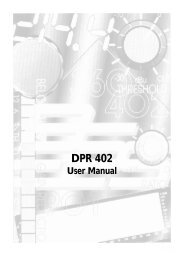
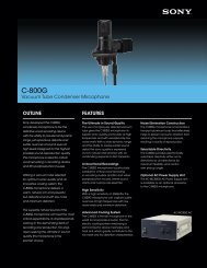
4.6 Equaliser Section<br />
Routing Buttons<br />
There are three buttons associated with this section of the unit. Section 5 describes the routing<br />
combinations in more detail but, briefly, these buttons function as described below.<br />
EQ IN – Switches the EQ section into circuit.<br />
DYN SC – Switches the EQ section into the sidechain of the Dynamics section. The Filter section can be<br />
switched independently of the EQ section. If both Filter and EQ sections are assigned to the dynamic<br />
sidechain the Filter section precedes the EQ.<br />
E – Switches the EQ from ‘G’ operation to ‘E’ operation – see below.<br />
Operation<br />
This is a 4-band equaliser that can be switched between two different sets of curves, one based on SSL’s G<br />
Series EQ and the other based on the latest version of the classic E Series EQ.<br />
HF Section: Frequency range 1.5kHz – 22kHz, gain ±20dB.<br />
LF Section: Frequency range 40Hz – 600Hz, gain ±16.5dB.<br />
The HF and LF sections provide shelving equalisers with variable turnover frequency. Normally the curve<br />
has a degree of overshoot/undershoot (depending on whether you are boosting or cutting) below the<br />
selected HF frequency (or above the selected LF frequency). Selecting the ‘E’ button removes the<br />
overshoot/undershoot effect and provides a slightly gentler slope. Selecting BELL in either mode switches<br />
the equaliser to a peaking curve.<br />
HMF Section: Centre frequency 600Hz – 7kHz, gain ±20dB, continuously variable Q (0.7 – 2.5).<br />
LMF Section: Centre frequency 200Hz to 2.5kHz, gain ±20dB, continuously variable Q (0.7 – 2.5).<br />
Normally, at any Q setting, the bandwidth of the HMF and LMF sections varies with gain, whereby an<br />
increase in boost or cut increases the selectivity of the EQ. This type of EQ can sound effective when used<br />
at moderate settings; the gentle Q curve lends itself to the application of overall EQ on combined sources<br />
and subtle corrective adjustments to instruments and vocals.<br />
When the EQ is switched to ‘E’ operation, the bandwidth of the HMF and LMF sections remains constant<br />
at all gains, so at lower gains the EQ curves are comparatively narrower for a given Q setting. This is<br />
particularly useful for drums, since relatively high Q is available at low gain settings. However, it is not<br />
so suitable for overall EQ or subtle corrections, as you need to adjust the Q to maintain the same effect<br />
when the gain is changed.<br />
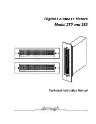
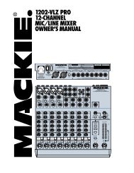
4.7 Output Section<br />
The Output section consists of a ±20dB output gain control, indented at<br />
centre and a 7-segment LED meter. Normally the meter reads the output of<br />
the channel, but selecting MTR INPUT will meter the signal immediately<br />
post the input section.<br />
The blue POWER LED indicates that the unit is powered (what else).<br />
The ADC LOCK LED indicates that the (optional) ADC card is locked to an<br />
external clock.<br />
OUTPUT<br />
MTR<br />
INPUT<br />
-20<br />
GAIN<br />
+20<br />
POWER<br />
ADC LOCK<br />
-24 -12 0 6 12 18 24<br />
Page 11