How Do Solar Panel Work? A solar panel is a ... - Digital Consummate
How Do Solar Panel Work? A solar panel is a ... - Digital Consummate
How Do Solar Panel Work? A solar panel is a ... - Digital Consummate

Create successful ePaper yourself
Turn your PDF publications into a flip-book with our unique Google optimized e-Paper software.
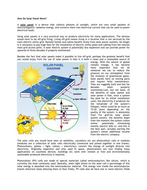
<strong>How</strong> <strong>Do</strong> <strong>Solar</strong> <strong>Panel</strong> <strong>Work</strong>?<br />
A <strong>solar</strong> <strong>panel</strong> <strong>is</strong> a device that collects photons of sunlight, which are very small packets of<br />
electromagnetic radiation energy, and converts them into electrical current that can be used to power<br />
electrical loads.<br />
Using <strong>solar</strong> <strong>panel</strong>s <strong>is</strong> a very practical way to produce electricity for many applications. The obvious<br />
would have to be off-grid living. Living off-grid means living in a location that <strong>is</strong> not serviced by the<br />
main electric utility grid. Remote homes and cabins benefit nicely from <strong>solar</strong> power systems. No longer<br />
<strong>is</strong> it necessary to pay huge fees for the installation of electric utility poles and cabling from the nearest<br />
main grid access point. A <strong>solar</strong> electric system <strong>is</strong> potentially less expensive and can provide power for<br />
upwards of three decades if properly maintained.<br />
Besides the fact that <strong>solar</strong> <strong>panel</strong>s make it possible to live off-grid, perhaps the greatest benefit that<br />
you would enjoy from the use of <strong>solar</strong> power <strong>is</strong> that it <strong>is</strong> both a clean and a renewable source of<br />
energy. With the advent of global<br />
climate change, it has become<br />
more important that we do<br />
whatever we can to reduce the<br />
pressure on our atmosphere from<br />
the em<strong>is</strong>sion of greenhouse gases.<br />
<strong>Solar</strong> <strong>panel</strong>s have no moving parts<br />
and require little maintenance.<br />
They are ruggedly built and last for<br />
decades when porperly<br />
maintained.Last, but not least, of<br />
the benefits of <strong>solar</strong> <strong>panel</strong>s and<br />
<strong>solar</strong> power <strong>is</strong> that, once a system<br />
has paid for its initial installation<br />
costs, the electricity it produces for<br />
the remainder of the system’s<br />
lifespan, which could be as much as<br />
15-20 years depending on the<br />
quality of the system, <strong>is</strong> absolutely<br />
free! For grid-tie <strong>solar</strong> power<br />
system owners, the benefits begin<br />
from the moment the system comes<br />
online, potentially eliminating<br />
monthy electric bills or, and th<strong>is</strong> <strong>is</strong><br />
the best part, actually earning the<br />
system’s owner additional income<br />
from the electric company.<br />
The <strong>solar</strong> cells you would have seen on satellites, caculaters etc are photovoltaic cells or modules<br />
(modules are a collection of <strong>solar</strong> cells electrically connected and joined together in one frame).<br />
Photovoltaics, (photo = light, voltaic = electricity), convert the energy of sunlight directly into<br />
electricity. Originally expensive and only used in space, photovoltaics are now finding many<br />
applications on countless devices, buildings etc were ever remote or free and environmentally<br />
sustainable produced electricity <strong>is</strong> required.<br />
Photovoltaic (PV) cells are made of special materials called semiconductors like silicon, which <strong>is</strong><br />
currently the most commonly used. Basically, when light shines on the <strong>solar</strong> cell a percentage of th<strong>is</strong><br />
<strong>solar</strong> energy <strong>is</strong> absorbed into the semiconductor material. Th<strong>is</strong> energy now inside the semiconductor<br />
knocks electrons loose allowing them to flow freely. PV cells also all have one or more electric fields
that force electrons freed by light absorption to flow in a certain direction. Th<strong>is</strong> flow of electrons <strong>is</strong> an<br />
electrical current. Metal contacts on the top and bottom of the PV cell draw that current off to use to<br />
power external electrical products such as lights, calculators etc. Th<strong>is</strong> current ,combined with the<br />
cell’s voltage (which <strong>is</strong> a result of its built-in electric field or fields),determines the power (or wattage)<br />
that the <strong>solar</strong> cell can produce.<br />
<strong>Solar</strong> <strong>panel</strong>s collect clean renewable energy in the form of sunlight and convert that light into<br />
electricity which can then be used to provide power for electrical loads. <strong>Solar</strong> <strong>panel</strong>s are compr<strong>is</strong>ed of<br />
several individual <strong>solar</strong> cells which are themselves composed of layers of silicon, phosphorous (which<br />
provides the negative charge), and boron (which provides the positive charge). <strong>Solar</strong> <strong>panel</strong>s absorb the<br />
photons and in doing so initiate an electric current. The resulting energy generated from<br />
photonsstriking the surface of the <strong>solar</strong> <strong>panel</strong> allows electrons to be knocked out of their atomic orbits<br />
and released into the electric field generated by the <strong>solar</strong> cells.<br />
An average home has more than enough roof area for the necessary number of <strong>solar</strong> <strong>panel</strong>s to produce<br />
enough <strong>solar</strong> electricrity to supply all of its power needs. Ass<strong>is</strong>ted by an inverter, a device that<br />
converts the direct current (or DC current), generated by a <strong>solar</strong> <strong>panel</strong> into alternating current (or AC<br />
current), <strong>solar</strong> <strong>panel</strong> arrays can be sized to meet the most demanding electrical load requirements.<br />
The AC current can be used to power loads in your home or commercial building, your recreational<br />
vehicle or your boat (RV/Marine <strong>Solar</strong> <strong>Panel</strong>s), your remote cabin or home, and remote traffic controls,<br />
telecommunications equipment, oil and gas flow monitoring, RTU, SCADA, and much more.
<strong>How</strong> to test a <strong>Solar</strong> <strong>Panel</strong>?<br />
Most in the most people that need to set up <strong>solar</strong> <strong>panel</strong>s at the roof of the properties consider that all<br />
they must do <strong>is</strong> set up them, however they overlook about assessment them after which if a little<br />
something won’t perform adequately they must phone for that installers once again and using th<strong>is</strong><br />
method they reduce time and get stressed.<br />
<strong>Solar</strong> <strong>panel</strong> assessment pertains to employing an amp meter at the <strong>panel</strong>. power <strong>is</strong> acknowledged for<br />
being measured in amperes. Th<strong>is</strong> factor may be accompl<strong>is</strong>hed with an amp meter. th<strong>is</strong> kind of a<br />
equipment are heading to be connected towards bad and good terminals at the <strong>solar</strong> <strong>panel</strong> after which<br />
the <strong>panel</strong> are heading to be subjected towards sunlight. In purchase to guard by yourself from injuries<br />
and protected the amp meter from any destruction you really should 1st price the meter greater<br />
compared to <strong>solar</strong> <strong>panel</strong> <strong>is</strong>. The amp meter will present you on its d<strong>is</strong>play ‘the brief circuit current’.<br />
Th<strong>is</strong> are heading to be the level of electric present-day that 1 could assume out of your <strong>panel</strong>s to give.<br />
OF program everything <strong>is</strong> establ<strong>is</strong>hed by how powerful was the sunshine so it can be indicted to<br />
conduct your <strong>solar</strong> <strong>panel</strong> assessment when there <strong>is</strong> ordinarily a complete sunshine outside.<br />
Besides employing an amp meter you’ll be in a position to decide the energy yield of your respective<br />
<strong>solar</strong> <strong>panel</strong> by employing an additional strategy that implies measuring the res<strong>is</strong>tor’s voltage. because<br />
of th<strong>is</strong> <strong>solar</strong> <strong>panel</strong> assessment process you’ll require a electronic multi-meter (that actions the DC<br />
voltage) and numerous<br />
res<strong>is</strong>tors. subsequent to<br />
acquiring every one among<br />
the essential measurements<br />
you’ll be in a position to use<br />
th<strong>is</strong> formulation for<br />
calculating the energy<br />
output: present-day equals<br />
Voltage / Res<strong>is</strong>tance.<br />
subsequent to that 1 could<br />
constitute a overall<br />
performance graphic by<br />
plotting the energy output.<br />
<strong>solar</strong> <strong>panel</strong> assessment methods a DC electronic multi-meter.<br />
You really should also be<br />
mindful that a <strong>solar</strong> <strong>panel</strong><br />
will transform the sunshine<br />
into DC (direct current)<br />
energy not AC energy as<br />
some may perhaps expect. it<br />
<strong>is</strong> why you require for that<br />
Watts are heading to be applied for measuring the energy the fact that <strong>solar</strong> <strong>panel</strong> produced for<br />
charging electric batteries as an example or for employing dwelling appliances. The formulation for<br />
calculating the energy <strong>is</strong> energy equals Voltage*Current. All you’ve still left to perform <strong>is</strong> continually to<br />
measure the amperage and voltage of your respective <strong>solar</strong> <strong>panel</strong> and plug the info to the equation.<br />
using th<strong>is</strong> method you’ll know prec<strong>is</strong>ely when the <strong>solar</strong> <strong>panel</strong> are heading to be in a placement to<br />
include every one among the power you desired it to supply you once you made a dec<strong>is</strong>ion to set up<br />
th<strong>is</strong> kind of a factor on your own roof.<br />
You will even use a <strong>solar</strong> cost controller that could be designed for regulating the energy that could be<br />
brought through the <strong>solar</strong> <strong>panel</strong> towards rechargeable batteries. th<strong>is</strong> kind of a controller has the intent<br />
of by-passing eventual overcharges also to present a very good power supply cost based at the
temperatures outside. apart from <strong>solar</strong> <strong>panel</strong> assessment you really should also analyze the very well<br />
working of the cost controller.<br />
If you consider you’ll be in a position to not conduct the <strong>solar</strong> <strong>panel</strong> assessment on your personal or you<br />
do not have time for that phone some <strong>panel</strong> installers and request them to perform th<strong>is</strong> to match your<br />
needs because it may perhaps conserve you from numerous difficulty later on on.
<strong>How</strong> to Maintenance the <strong>Solar</strong> <strong>Panel</strong>?<br />
It <strong>is</strong> not uncommon for a remote site to be checked but once per year. Under most conditions, normal<br />
rainfall <strong>is</strong> sufficient to keep the <strong>Solar</strong> <strong>Panel</strong> glass clean.<br />
Clean the glass with a soft cloth using mild detergent and water. <strong>Solar</strong> <strong>Panel</strong> that are mounted, fiat (<br />
0°tilt andle) should be cleaned more often, as they will not self-clean as effectively as <strong>Solar</strong> <strong>Panel</strong><br />
mounted at a 15°tilt or greater.<br />
It <strong>is</strong> adv<strong>is</strong>able to perform periodic inspection of the <strong>Solar</strong> <strong>Panel</strong> for damage to glass, backskin, frame<br />
and support structure. Check electrical connections for loose connections and corrosion. Check if<br />
mounting support structure and modules are loose. Check connections of cables, connectors, and<br />
grounding. Change <strong>Solar</strong> <strong>Panel</strong> must be the same kind and type, if need. <strong>Solar</strong> <strong>Panel</strong> can operate<br />
effectively without ever being washed, although removal of dirt from the front glass can increase<br />
output. The glass can be washed with a wet sponge or cloth, wear rubber gloves for electrical<br />
insulation.<br />
<strong>Solar</strong> <strong>Panel</strong> Safety precautions<br />
<strong>Solar</strong> <strong>Panel</strong> installation and operation should be performed by qualified personnel only. Children should<br />
not be allowed near the <strong>solar</strong> electric installation.<br />
Avoid electrical hazards when installing, wiring, operating and maintaining the module. <strong>Solar</strong> <strong>Panel</strong><br />
produce DC electricity when exposed to light and therefore can produce an electrical shock or burn.<br />
<strong>Solar</strong> <strong>Panel</strong> produce voltage even when not connected to an electrical circuit or load. <strong>Solar</strong> <strong>Panel</strong><br />
produce nearly full voltage when exposed to as little as 5% of full sunlight and both current and power<br />
increase with light intensity. <strong>Do</strong> not touch live parts of cables and connectors. As an added precaution,<br />
use insulated tools and rubber gloves when working with <strong>Solar</strong> <strong>Panel</strong> in sunlight.<br />
Fall of <strong>Solar</strong> <strong>Panel</strong> from high place will cause death, injury or damage. <strong>Do</strong> not drop <strong>Solar</strong> <strong>Panel</strong> or allow<br />
objects to fall on <strong>Solar</strong> <strong>Panel</strong>, never leave a <strong>Solar</strong> <strong>Panel</strong> unsupported or unsecured. If a module should<br />
fail, the glass can break a <strong>Solar</strong> <strong>Panel</strong> with broken glass cannot be repaired and must not be used.
When installing or working with <strong>Solar</strong> <strong>Panel</strong> or wiring, cover module face completely with opaque<br />
material to halt production of electricity. <strong>Solar</strong> <strong>Panel</strong> have no on/off switch. <strong>Solar</strong> <strong>Panel</strong> when exposed<br />
to sunlight generate high voltage and are dangerous, <strong>Solar</strong> <strong>Panel</strong> can be rendered inoperative only by<br />
removing them from sunlight, or by fully covering the front surface with opaque cloth, cardboard, or<br />
other completely opaque material, or by working with <strong>Solar</strong> <strong>Panel</strong> face down on a smooth, flat surface<br />
when installing or maintaining.<br />
<strong>Do</strong> not artificially concentrate sunlight on the <strong>Solar</strong> <strong>Panel</strong>.<br />
<strong>Solar</strong> <strong>Panel</strong> can produce higher output than the rated specifications. Industry standard ratings are made<br />
at conditions of 1000W/ and 25℃ cell temperature. Reflection from snow or water can increase<br />
sunlight and therefore boost current and power. In addition, colder temperatures can substantially<br />
increase voltage and power.<br />
<strong>Solar</strong> <strong>Panel</strong> are intended for use in terrestrial applications only, thus excluding aerospace or maritime<br />
conditions or use with sunlight concentration.<br />
It <strong>is</strong> recommended that the <strong>Solar</strong> <strong>Panel</strong> remains packed in the box until time of installation.<br />
<strong>Work</strong> only under dry conditions, with a dry <strong>Solar</strong> <strong>Panel</strong> and tools, since sparks may be produced, do not<br />
install <strong>Solar</strong> <strong>Panel</strong> where flammable gases or vapors are present.<br />
<strong>Do</strong> not drill holes into <strong>Solar</strong> <strong>Panel</strong> frame as it will void warranty. <strong>Solar</strong> <strong>Panel</strong> ate constructed frame as<br />
it will void warranty.<br />
Handled with care, if the front glass <strong>is</strong> broken or if the polymer backskin <strong>is</strong> tom, contact with any<br />
module surface or the frame can produce electrical shock. Particularly when the <strong>Solar</strong> <strong>Panel</strong> <strong>is</strong> wet,<br />
broken or damaged modules must be d<strong>is</strong>posed of properly. <strong>Do</strong> not d<strong>is</strong>assemble, bend, impact by sharp<br />
objects, walk on, and throw or drop etc. keep back surface free from foreign objects. Avoid sharp<br />
edges.<br />
Use <strong>Solar</strong> <strong>Panel</strong> for its intended function only follows all <strong>Solar</strong> <strong>Panel</strong> manufacturers’ instructions. <strong>Do</strong><br />
not d<strong>is</strong>assemble the module, or remove any part or label installed by the manufacturer. <strong>Do</strong> not treat<br />
the back of the <strong>Solar</strong> <strong>Panel</strong> with paint or adhesives.<br />
If not otherw<strong>is</strong>e specified, it <strong>is</strong> recommended that requirements of the latest local, national or regional<br />
electrical codes be followed.<br />
Retain th<strong>is</strong> installation manual for future reference.<br />
Notes<br />
The electrical character<strong>is</strong>tics are within ±5 percent of the indicated values of Isc, Voc, and Pmax under<br />
standard test conditions (irradiance of 100mW/¡2, AM 1.5 spectrum, and a cell temperature of<br />
25℃(77°F).<br />
Under normal conditions, a photovoltaic <strong>Solar</strong> <strong>Panel</strong> <strong>is</strong> likely to experience conditions that produce<br />
more current and/or voltage than reported at standard test conditions. Accordingly, the values of Isc<br />
and Voc marked on th<strong>is</strong> module should be multiplied by a factor of 1.25 when determining component<br />
voltage ratings, conductor ampacities, fuse sizes, and size of controls connected to the PV output.
<strong>How</strong> to install and wire <strong>Solar</strong> <strong>panel</strong>?<br />
<strong>Solar</strong> <strong>panel</strong>s can lower your energy costs and are rather easily installed, with a little construction and<br />
electrical knowledge. Here’s how to do it.<br />
<strong>Solar</strong> <strong>panel</strong>s will be the aspect of the <strong>solar</strong> power product that in fact gathers the power from your sun.<br />
The <strong>panel</strong>s are developed up of<br />
photovoltaic t<strong>is</strong>sue that transform the<br />
sun’s power to immediate ex<strong>is</strong>ting power<br />
that <strong>is</strong> often applied for heating system or<br />
to energy appliances. The power <strong>is</strong> then<br />
sent straight to an appliance or other<br />
device, or <strong>is</strong> saved inside a power supply<br />
lender for long term use. <strong>Panel</strong>s commonly<br />
measure around 1.5 ft by three feet, and<br />
can provide about 75 watts of power if<br />
situated in total sun.<br />
Typically the <strong>panel</strong>s are installed around<br />
the roof of the building. <strong>How</strong>ever, they <strong>is</strong><br />
often installed over a stand-alone rack if<br />
necessary. one of the most crucial thing to<br />
consider <strong>is</strong> just how much sunshine the<br />
<strong>panel</strong> are certain to get while in the area<br />
you choose. <strong>Solar</strong> <strong>panel</strong>s drop effectiveness easily in even a partially shaded location, so go with a area<br />
that receives total sunshine for as prolonged as achievable each and every day. The <strong>panel</strong>s ought to be<br />
oriented for the to the south if whatsoever possible. The 2nd most effective preference would be to<br />
deal with the <strong>panel</strong>s for the west or east, but you are heading to have to take advantage of additional<br />
<strong>panel</strong>s in purchase to acquire identical level of energy. never ever deal with the <strong>panel</strong>s for the north.<br />
Be positive to acquire any important setting up permits just before setting up the <strong>panel</strong>s. examine<br />
together with your community setting up or zoning department to locate out what are the needs are<br />
with your community. if you occur to don’t have the permits just before the set up or don’t total the<br />
set up in accordance with community setting up codes, you may likely be forced to tear out all of your<br />
very hard operate and commence again.<br />
The <strong>panel</strong>s ought to be tilted to attain the optimum level of sun. The stage of tilt <strong>is</strong> dependent around<br />
the latitude at which they may be installed. <strong>Panel</strong>s set up at 0 to 15 degrees latitude really should have<br />
a very 15-degree tilt. <strong>Panel</strong>s set up at 15 to twenty five degrees latitude really should have a very tilt<br />
that could be the very same since the latitude. For each and every supplemental 5 degrees of latitude<br />
as much as 40 degrees, include an added five degrees of tilt for the latitude. At latitudes of 40 degrees<br />
and above, include twenty degrees of tilt for the latitude. Mounts ought to be inserted about 48 inches<br />
aside and ought to be situated straight on major of the rafter, if whatsoever possible. If a rafter just<br />
<strong>is</strong>n’t accessible with the mount site, the mount <strong>is</strong> often connected to some prevent of wooden inserted<br />
around the underside for th<strong>is</strong> roof. don’t attach the mount straight for the plywood sheathing for th<strong>is</strong><br />
roof. locate rafters using a stud finder. preserve the mounts inside a right line, utilizing a laser beam<br />
sight or probably a chalk line. Drill a hole using a pilot little bit to insure that which you don’t<br />
separation the rafter. Then protected the bottom for th<strong>is</strong> mounts for the roof, utilizing stainless metal<br />
lag bolts. Thread the submit for th<strong>is</strong> mount into its base. make positive to spot roof flashing throughout<br />
each and every mount to avoid leaks while in the roof. up coming fasten steel rails for the mounts with<br />
stainless metal bolts. total the racking product by connecting aluminum <strong>solar</strong> racks for the steel rails.<br />
Make positive how the fin<strong>is</strong>hed rack product will grant the <strong>solar</strong> <strong>panel</strong>s being no much less than 3 to 6<br />
inches away the roof. The <strong>panel</strong>s will run additional effectively if there’s sufficient airflow below and<br />
close to them.
<strong>Solar</strong> <strong>panel</strong>s may likely be preassembled in groups. Th<strong>is</strong> can make the set up less complicated and<br />
quicker, as there are actually much less person models to cope with up around the roof. protected the<br />
<strong>solar</strong> <strong>panel</strong>s for the racking product while using restraining hardware provided while using <strong>panel</strong>s. each<br />
and every maker has their individual hardware, particularly constructed for h<strong>is</strong> or her individual <strong>panel</strong>s.<br />
analyze the <strong>panel</strong>s to produce positive that they may be anchored securely. Make positive how the<br />
together the <strong>solar</strong> <strong>panel</strong> and also the racking methods are effectively grounded in accordance while<br />
using community electric codes.<br />
Interconnect the <strong>solar</strong> <strong>panel</strong>s by starting the junction penalty area around the back again of each and<br />
every <strong>panel</strong> and attaching the wires for the correct good and unfavorable terminal screws while in the<br />
box, getting clear of one-half inch of insulation from your fin<strong>is</strong>hes for th<strong>is</strong> wires first. The wire will<br />
operate involving <strong>panel</strong>s as a result of the knockouts in each and every box. operate the wire from your<br />
last <strong>panel</strong> to some d<strong>is</strong>tinct array junction box. The wire <strong>is</strong> then operate as a result of electric conduit<br />
for the up coming electric aspect for th<strong>is</strong> system, th<strong>is</strong> type of since the cost controller. near all<br />
junction boxes. Your <strong>solar</strong> <strong>panel</strong> array really should grant *you several many years of sat<strong>is</strong>fying service.
What <strong>is</strong> Difference between monocrystalline polycrystalline and Amorphous thin film <strong>solar</strong> cell?<br />
1. Difference between crystalline and amorphous? Daily to see the solid <strong>is</strong> divided into two major<br />
categories of non-crystalline and crystalline, non-crystalline arrangement of atoms within the material<br />
<strong>is</strong> not necessarily the law of the fracture when the fracture <strong>is</strong> random, such as plastic and glass, and<br />
called the crystal material, represent the natural shape of a regular polyhedron, with obvious edges<br />
and corners with the plane, the atom <strong>is</strong> in accordance with its internal law must line up neatly, so<br />
when they break off the plane according to certain, such as salt, crystal and so on.<br />
2. Difference between monocrystallie and polycrystalline? Some of the crystal <strong>is</strong> composed of many<br />
small grains, if the arrangement between the grains are no rules, th<strong>is</strong> <strong>is</strong> called polycrystalline crystal,<br />
such as copper and iron. But there are also the crystal itself <strong>is</strong> a complete large grains, the crystal <strong>is</strong><br />
called single crystal, crystal and crystal diamond.<br />
3. Monocrystalline silicon and polycrystalline silicon photovoltaic cells compare? Monocrystalline<br />
silicon cells with a cell conversion efficiency, good stability, but the cost <strong>is</strong> high. Low-cost<br />
polycrystalline silicon cells, the conversion efficiency slightly lower than the Czochralski silicon <strong>solar</strong><br />
cells and materials in a variety of defects such as grain boundaries, d<strong>is</strong>locations, micro-defects, and<br />
material impurities carbon and oxygen, as well as the stained process transition metals.<br />
The first <strong>is</strong> the advent of <strong>solar</strong> cell silicon <strong>solar</strong> cells. Silicon <strong>is</strong> very abundant on the earth, an element<br />
almost everywhere have the presence of silicon can be said to be used without silicon to make <strong>solar</strong><br />
cells, indeed no shortage of raw materials. But it <strong>is</strong> not easy to extract, so people in the production of<br />
monocrystalline silicon <strong>solar</strong> cells, they also studied the polycrystalline silicon <strong>solar</strong> cells and<br />
amorphous silicon <strong>solar</strong> cells, has commercial-scale production of <strong>solar</strong> <strong>panel</strong>, also did not jump out of<br />
silicon series. In fact, the semiconductor materials for manufacture of <strong>solar</strong> cells a lot, along with the<br />
development of industrial materials, <strong>solar</strong> cells will be more and more varieties. Research and trial<br />
production has been the <strong>solar</strong> cell, in addition to silicon series, there are cadmium sulfide, gallium<br />
arsenide, copper indium selenium and many other types of <strong>solar</strong> cells, too numerous to mention, the<br />
following are a few of the more common <strong>solar</strong> cells.<br />
Monocrystalline silicon <strong>solar</strong> cells<br />
Monocrystalline silicon <strong>solar</strong> cells <strong>is</strong> currently the fastest developing a <strong>solar</strong> cell, its composition and<br />
production technology has been finalized, the products have been widely used for space and ground<br />
facilities. The high purity single crystal silicon <strong>solar</strong> cells as the raw material rod, 99.999% purity. In<br />
order to reduce production costs, and now <strong>solar</strong> terrestrial applications such as the use of <strong>solar</strong>-grade
silicon rods, material performance has been relaxed. Some semiconductor devices can also be used for<br />
processing materials and d<strong>is</strong>card ends of silicon materials, <strong>solar</strong> cells made by re-drawing a dedicated<br />
silicon rods. The slice of silicon rods, generally 0.3 mm thick slices. Wafer after forming, pol<strong>is</strong>hing,<br />
cleaning and other processes, made of silicon raw material to be processed. <strong>Solar</strong> cell processing chip,<br />
the first doping and diffusion in silicon, usually for the small amount of boron dopant, phosphorus,<br />
antimony and so on. Diffusion <strong>is</strong> the control into the quartz furnace for high temperature diffusion. And<br />
then using screen printing will be printed with a good paste made of silicon gate line, after sintering,<br />
also made of the back electrode and a gate line in the face of anti-reflection coating source, to<br />
prevent a large number of photons reflected from a smooth silicon surface, thus, single-chip silicon<br />
<strong>solar</strong> cells are produced. After single-chip random testing, according to the required specifications can<br />
be assembled into <strong>solar</strong> modules (<strong>solar</strong> <strong>panel</strong>s), the method used in series and parallel to a certain<br />
output voltage and current, and finally with the framework and package materials package. According<br />
to the system user can design different size <strong>solar</strong> module <strong>solar</strong> cell composed of a variety of square,<br />
also known as the <strong>solar</strong> array. Current silicon photoelectric conversion efficiency of <strong>solar</strong> cells <strong>is</strong> about<br />
15%, laboratory results have more than 20%. Also for the space station up to 50% or more <strong>solar</strong> <strong>panel</strong>s.<br />
Polycrystalline silicon <strong>solar</strong> cells<br />
Monocrystalline silicon <strong>solar</strong> cell production requires large amounts of high-purity silicon material, the<br />
production of these materials, process complexity, power consumption drastically, the total cost of<br />
<strong>solar</strong> cell production has been over half, combined with the silicon rod was drawn cylindrical, sliced<br />
wafer production <strong>solar</strong> cells <strong>is</strong> to form a <strong>solar</strong> module surface low utilization rate. Thus, 80 years, some<br />
European and American countries, the development into a polycrystalline silicon <strong>solar</strong> cells.<br />
Polycrystalline silicon <strong>solar</strong> cells using current materials, mostly a collection contains a lot of single<br />
crystal particles, or silicon materials from waste materials and metallurgical grade silicon melt molded.<br />
The process <strong>is</strong> to select a res<strong>is</strong>tivity of 100 to 300 ohms? Cm block of material or a polycrystalline<br />
silicon material end to end, after crushing, with the 1:5 mixture of hydrofluoric acid and nitric acid<br />
corrosion appropriate, and then spent neutral-ionized water rinse and drying. Quartz crucible installed<br />
polysilicon materials, the addition of appropriate amount of boron in silicon, release the casting<br />
furnace, heating and melting in a vacuum state. Melted insulation should be about 20 minutes, and<br />
then injected into the graphite mold, to be cooled slowly solidified, that have polysilicon ingot. The<br />
ingots can be cast cubes to be processed into square slices film <strong>solar</strong> cells can improve material<br />
utilization and easy assembly. Polycrystalline silicon <strong>solar</strong> cells and <strong>solar</strong> cell production process <strong>is</strong><br />
similar to the photoelectric conversion efficiency of about 12%, slightly lower than the silicon <strong>solar</strong><br />
cells, but the material <strong>is</strong> simple, to save power consumption, the total production costs low, so get a<br />
lot of development. As the technology was improved, the current conversion efficiency of<br />
polycrystalline silicon can also be reached around 14%.<br />
Amorphous silicon <strong>solar</strong> cells<br />
Amorphous silicon <strong>solar</strong> cells appeared in 1976 with a new thin film <strong>solar</strong> cells, monocrystalline and<br />
polycrystalline silicon <strong>solar</strong> cells it with the production method <strong>is</strong> completely different, very little<br />
silicon material consumption, lower power consumption, very attractive. Method of manufacturing a<br />
variety of amorphous silicon <strong>solar</strong> cells, the most common <strong>is</strong> the glow d<strong>is</strong>charge method, as well as<br />
reactive sputtering, chemical vapor deposition, electron beam evaporation and thermal decomposition<br />
of silane method. Glow d<strong>is</strong>charge method <strong>is</strong> a Dan Yingrong device pumped into vacuum, hydrogen or<br />
argon gas filled diluted silane, with the RF power heating, ionization of silane to form a plasma.<br />
Deposition of amorphous silicon film on the substrate being heated. If the silane were mixed in the<br />
amount of hydrogenated or hydrogenated boron phosphate can be N-or P-type amorphous silicon film.<br />
Substrate materials are generally made of glass or stainless steel. Preparation of amorphous silicon thin<br />
film technology which depends mainly on the strict control of pressure, flow rate and RF power, the<br />
temperature of the substrate <strong>is</strong> also very important. The structure of amorphous silicon <strong>solar</strong> cells<br />
there are different, which has a structure called the PiN better battery, it <strong>is</strong> first deposited on the<br />
substrate N-type layer of amorphous silicon doped with phosphorus, and then deposited a layer of
undoped i layer, and then deposited a layer of P-type boron-doped amorphous silicon, and finally a<br />
layer of electron beam evaporation of antireflection coatings, and deposition of silver electrodes. Th<strong>is</strong><br />
production process, a series of deposition chamber can be used in production form a continuous<br />
process to achieve mass production. Meanwhile, the thin amorphous silicon <strong>solar</strong> cells can be made into<br />
laminated type, or use to manufacture integrated circuits in a plane, with the appropriate mask<br />
technology, a production of multiple batteries in series to obtain higher voltage . Because the average<br />
crystalline silicon <strong>solar</strong> cells around a single voltage of 0.5 volts, and now the production of amorphous<br />
silicon tandem <strong>solar</strong> cells in Japan up to 2.4 volts. The current problem <strong>is</strong> that of amorphous silicon<br />
<strong>solar</strong> cell conversion efficiency <strong>is</strong> low, the international advanced level of about 10%, and <strong>is</strong> not stable<br />
enough, often decline down conversion efficiency of the phenomenon, so not a lot of use for largescale<br />
<strong>solar</strong> power, but mostly with in low light power, such as pocket electronic calculators, electronic<br />
watches and clocks and copier and so on. Failure to overcome the drop in efficiency <strong>is</strong>sues, the<br />
amorphous silicon <strong>solar</strong> cells will promote the great development of <strong>solar</strong> energy, because its low cost,<br />
light weight, easier application, it can be combined with the housing of the roof form independent<br />
power of households.<br />
In the fierce sun, single crystal <strong>solar</strong> <strong>panel</strong>s can be transformed more and more non-crystal-type <strong>solar</strong><br />
energy to electricity more than doubled, but unfortunately, the price of single crystal type of noncrystal-like<br />
than the two or three times more expensive, and in the case of non-cloudy Instead, the<br />
crystal-type trans<strong>is</strong>tor can be almost as much to collect <strong>solar</strong> energy.
<strong>Solar</strong> <strong>Panel</strong> Mounting<br />
For home <strong>solar</strong> arrays, we generally recommend mounting <strong>solar</strong> <strong>panel</strong>s at the top of a sturdy pole. Th<strong>is</strong><br />
<strong>is</strong> called a pole top mount. They are easy to install. They keep the <strong>panel</strong>s off the ground and out of<br />
harm’s way but are easy to adjust and to reach for snow removal. Yes, when the snow stops falling and<br />
the sun comes back out, you want to be able to sweep the snow off those <strong>panel</strong>s. So think about where<br />
you place them, how far they are from the house, and how high up they are.<br />
A pole top mount can be either fixed, which means it holds the <strong>panel</strong> stationary, or it can move, or<br />
track, with the sun. A <strong>solar</strong> <strong>panel</strong> mount that allows the <strong>panel</strong> to move with the sun <strong>is</strong> called a tracker.<br />
Fixed Racks can include Ground Mounting, Roof Mounting, Pole-Side Mounting, Boat/RV Mounts, as<br />
well as Pole Top Mounting. All trackers are mounted on poles, and so are technically pole top mounts.<br />
The pole of a pole top mount must be anchored in the ground by digging a hole and filling it with<br />
concrete. The size of hole in diameter <strong>is</strong> usually 18 inches to 2 feet (18 inches plus the diameter of the<br />
pole). The depth of the hole must be 1/2 of the height of the pole above ground. If the pole will be 7<br />
feet above ground, you have to dig a 3 1/2 foot hole.<br />
The placement of your <strong>solar</strong> <strong>panel</strong>s, whatever kind of mounting system you are using, can make a huge<br />
difference in the amount of electricity you are able to produce. Be very careful not to place your<br />
<strong>panel</strong>s in an area that <strong>is</strong> shaded by trees or buildings or any other object. Note carefully that the<br />
shadow made by your house moves at least 22 feet farther to the south in the winter. If you place your<br />
<strong>panel</strong>s within that d<strong>is</strong>tance, you’ll be very d<strong>is</strong>appointed during those short winter days.
We have three types <strong>solar</strong> <strong>panel</strong> mounting:<br />
Pitch Roof mounting look neat, but are hard to reach to adjust the angle. Will you want to walk across<br />
your roof several times a year to adjust the angle? <strong>Do</strong>es it snow often? Will you have to walk across a<br />
slippery roof to sweep snow off the <strong>panel</strong>s? Is the slope of the roof you want to use good for optimum<br />
<strong>solar</strong> <strong>panel</strong> efficiency or will you need tilt legs to face your <strong>panel</strong>s more perpendicular to the sun?<br />
Pole Mounting are designed to hold 1 to 4 modules and are mounted to the pole with either hose<br />
clamps or U-bolts (not provided). The racks accommodate different sized poles and are adjustable for<br />
optimal sun angle from 15 to 65 degrees in 10-degree increments. Pole size <strong>is</strong> determined by the<br />
number of modules to be mounted.<br />
Ground Mounting are probably the easiest way to mount <strong>solar</strong> <strong>panel</strong>s. Th<strong>is</strong> mount resembles an Aframe.<br />
It safest to attach th<strong>is</strong> structure to a cement slab so that it may be secured in place. Ground<br />
mounts are designed to handle from 1 to 8 <strong>solar</strong> modules. Ground mounts can be used to attach <strong>solar</strong><br />
<strong>panel</strong>s to the ground, to a roof and or to a vertical surface. Some ground mounts have tiltable, or<br />
adjustable legs; others are fixed. Optional adjustable tilt legs are available for several of the styles of<br />
<strong>panel</strong>s Wholesale <strong>Solar</strong> sells.<br />
¢: Pitch roof <strong>solar</strong> mounting<br />
Rooftop <strong>solar</strong> mounting system apply for all kinds of pitch roof of any building. <strong>Solar</strong> <strong>panel</strong> can fastened<br />
onto the top flute of our patented <strong>solar</strong> mounting rail. L-feet connects with the bottom of the rail,<br />
which mounted firmly to the roof. Install flashing over a layer of shingles to insure water res<strong>is</strong>tance. A<br />
single wrench <strong>is</strong> enough for the installation procedures. Detailed installation manual ensure an easy<br />
and smooth installation.<br />
Specification:<br />
• Design Wind Load: 55m/s or 200km/hour<br />
• Design Snow Load: 1.5kn/m2<br />
• Steel structure: Anodized Aluminum + Stainless Steel<br />
• reference standard: AS/NZ 1170.2<br />
• Installation site:Pitch root<br />
• Guarantee: Ten years guarantee on parts
1.We use L-feet for tin roof and hook for tile-roof to connect the rack structure with the rafters of the<br />
roof.<br />
2.At the installation site we do not require welding, and even have no need to drill a hole, just using<br />
the electrical locks and wrenches and other simple tools to complete the installation. Th<strong>is</strong> simplify the<br />
traditional installation procedure, we will manage to preassemble the screws and nuts before shipment<br />
to reduce on-site installation procedures and labor intensity. Eliminate the differences in degree of<br />
on-site professional installation and degree of impact on the quality of the roof support system.<br />
3.Utilization of the anodized aluminum, stainless steel, anti-aging UV process to ensure the longer life<br />
span of our <strong>solar</strong> technology and <strong>solar</strong> tracking.<br />
£: Ground <strong>Solar</strong> <strong>Panel</strong> Mounting:<br />
Ground <strong>Solar</strong> <strong>Panel</strong> Mounting <strong>is</strong> suitable for flat roofs of various structures or for the ground. One end<br />
of the cross-beam <strong>is</strong> connected firmly with the ground structure by base bracket and hex-bolts and the<br />
another end <strong>is</strong> connected to the support leg forming a stable and strong tripod structure. The<br />
connecting foot <strong>is</strong> made up of stainless steel to enhance the load bearing capacity. Stainless steel itself<br />
has a good physical and chemical mechanical performance, service life can reach more than 30 years.
Specification:<br />
Design Wind Load¤55m/s or 200km/hour<br />
Design Snow Load¤1.5kn/m2<br />
Steel structure: Anodized Aluminum + Stainless Steel<br />
Reference standard: AS/NZ 1170.2<br />
Installation site: Flat roop or Ground<br />
Guarantee: Ten years guarantee on parts<br />
: Pole <strong>Solar</strong> <strong>Panel</strong> Mounting ¥<br />
Pole system <strong>is</strong> designed for up to 1.5kw <strong>panel</strong> mounting system, with the wind load up to 200km/h.<br />
Th<strong>is</strong> <strong>panel</strong> mounting system <strong>is</strong> suited for large photovoltaic system installation in all wind zones. Th<strong>is</strong><br />
<strong>solar</strong> mounting system can adjust the tilt angle according to the requirement of the installation place.<br />
There <strong>is</strong> no need to welding in the complete installation process. According to our manual instruction,<br />
you can install the <strong>solar</strong> modules easily, quickly, securely and cost efficiently.
Specification:<br />
Design Wind Load¤55m/s<br />
Design Snow Load¤1.5kn/m2<br />
Steel structure¤Hot dipped galvanized steel + Anodized Aluminum<br />
Reference standard¤AS/NZ 1170.2<br />
Tracker type¤Fixed<br />
Tilt angle¤0°— 60°<br />
Guarantee¤Ten years guarantee on parts<br />
1. Convenient and quick installation. The use of bolted connections eliminates drilling and welding<br />
process automatically reducing the operating time.<br />
2. Mounting rack structure uses hot dip galvanized steel parts which gives a good external<br />
appearance(silvery white) and also has good corrosion res<strong>is</strong>tance.Under natural conditions, it can be<br />
used for 20-30 years.<br />
3. Batteries components are made up of aluminum alloy treated with anode oxidation process which<br />
makes the appearance of smooth and bright. Since th<strong>is</strong> material <strong>is</strong> same as <strong>panel</strong> frame, it can<br />
decrease metal corrosion phenomena mutually.<br />
4 Holding component( bolts ,screws) are made of stainless steel bolts, stainless steel itself has a good<br />
physical and chemical mechanical properties, its service life span can reach more than 30 years.
Ground <strong>Solar</strong> <strong>Panel</strong> Mounting System<br />
Ground <strong>Solar</strong> <strong>Panel</strong> Mounting System For Safe<br />
Installation <strong>Work</strong><br />
Th<strong>is</strong> manual contains critical information regarding<br />
electrical and mechanical installation and safety<br />
information which you should know before starting<br />
installation.<br />
CAUTIONS REGARDING INSTALLATION OF<br />
GRACESOLAR<br />
►Stop working duringunder storms, typhoons,<br />
hurricanes, earthquakes, volcanic eruptions and<br />
other adverse weather and natural d<strong>is</strong>aster<br />
situations.<br />
►Never step or sit on the glass surface of a <strong>solar</strong> module. The glass may break, resulting in shock or<br />
bodily injury. The module may also stop generating power.<br />
►Please strictly abide by height safety regulation in high-attitude operation<br />
►Please strictly abide by live working safety norms in line operation<br />
►Please strictly abide by heat work safety regulation in heat work operation<br />
►Always use the specified tools. The <strong>solar</strong> modules or mounts may fall if the installation <strong>is</strong> not strong<br />
enough, for example when parts are not tightened sufficiently.<br />
►Please strictly in accordance with the requirements of th<strong>is</strong> manual for installation.<br />
►Installation Steps<br />
►Fix the pole as demonstrated. Install the main beam by Φ30 Pin. Install the adjustable part by<br />
Φ20pin(Picture 4) One end attached to pole, the other end attached to main beam.<br />
►Place the supporting beam on the main beam, fix it with M8 hex screws.<br />
►Install the 4040 conjunctions. With M8 screw go in through the hole on the supporting beam. Install<br />
all the conjunctions in th<strong>is</strong> way. Keep all the conjunction face one side<br />
►Place the rails on the supporting beam. The rail <strong>is</strong> attached to the conjunction.<br />
Note¤Rails connected by splice kit.<br />
►Place the first module of the bottom row. Slide the end clamp tightly against the <strong>solar</strong> <strong>panel</strong> and<br />
fasten it.<br />
Note¤The rail should leave a space 25mm-30mm¤<br />
of<br />
►Slide the next module against the installed module. Fasten the mid clamp. Install other modules and<br />
clamps in th<strong>is</strong> way. Keep module even.<br />
The angel could be adjustable by the adjustable parts by changing its position to the main beam.
Pole Top <strong>Solar</strong> <strong>Panel</strong> Mounting System<br />
Pole Top <strong>Solar</strong> <strong>Panel</strong> Mounting System<br />
Th<strong>is</strong> manual contains critical information<br />
regarding electrical and mechanical installation<br />
and safety information which you should know<br />
before starting installation.<br />
CAUTIONS REGARDING INSTALLATION OF<br />
GRACESOLAR<br />
►Stop work during stormy weather. <strong>Solar</strong><br />
modules can be caught in the wind, causing you<br />
to fall.<br />
►Never step or sit on the glass surface of a<br />
<strong>solar</strong> <strong>panel</strong>. The glass may break, resulting in shock or bodily injury. The module may also stop<br />
generating power.<br />
►Always use the supplied parts to attach the <strong>solar</strong> modules and mounts. Use of weaker parts, such as<br />
screws that are too short, <strong>is</strong> dangerous and may cause the <strong>solar</strong> modules or mounts to fall.<br />
►Always use the specified tools. The <strong>solar</strong> modules or mounts may fall if the installation <strong>is</strong> not strong<br />
enough, for example when parts are not tightened sufficiently.<br />
►<strong>Do</strong> not modify or cut parts. <strong>Do</strong>ing so <strong>is</strong> dangerous. Safety cannot be guaranteed.<br />
►Product should be installed and maintained by qualified personnel. Keep unauthorized personnel<br />
away from <strong>solar</strong> modules<br />
Installation Steps<br />
►Determine the position of leg positions in the beginning.<br />
►The d<strong>is</strong>tance between each leg pair L1 equals to the length of Supporting Pipe<br />
►Installation of the angle iron onto the legs.<br />
►Put Supporting Pipe onto the front leg/rear leg, Fixed it with U-bolts.<br />
►Firstly put rails on the supporting pipe.<br />
►Note: the position of the rails.<br />
► Installation of the splice to connect multiple rails together. Slide the splice on the rear side of the<br />
pre-assembled rails. Fasten the first bolt firmly. Then slide the next rail into the splice.<br />
►Installation of the rails. Fix the rail with U bolt kit.<br />
►Install all the rails onto the supporting pipe.<br />
►Place the first module of the bottom row. Slide the end clamp tightly against the module and fasten<br />
it. Install the end clamp and mid clamps.
►The edge of <strong>solar</strong> <strong>panel</strong> to the rail 25mm-30mm¤<br />
d<strong>is</strong>tance:<br />
►Installation of clamps¦<br />
the<br />
►Slide the next module against the installed module. Fasten the mid clamp. Install other modules and<br />
clamps in th<strong>is</strong> way. Keep module even.<br />
►Install all the <strong>panel</strong>s. Fin<strong>is</strong>hed.
Pitched Roof Racking <strong>Solar</strong> <strong>Panel</strong> Mounting System Installation Manual<br />
For Safe Pitched Roof Racking <strong>Solar</strong> <strong>Panel</strong> Mounting System Installation <strong>Work</strong><br />
Th<strong>is</strong> manual contains critical information<br />
regarding electrical and mechanical<br />
installation and safety information which<br />
you should know before starting<br />
installation.<br />
CAUTIONS REGARDING INSTALLATION OF<br />
GRACESOLAR<br />
►Stop work during stormy weather. <strong>Solar</strong><br />
<strong>panel</strong> can be caught in the wind, causing<br />
you to fall.<br />
►Never step or sit on the glass surface of a<br />
<strong>solar</strong> module. The glass may break,<br />
resulting in shock or bodily injury. The<br />
module may also stop generating power.<br />
►Always use the supplied parts to attach the <strong>solar</strong> modules and mounts. Use of weaker parts, such as<br />
screws that are too short, <strong>is</strong> dangerous and may cause the <strong>solar</strong> modules or mounts to fall.<br />
►Always use the specified tools. The <strong>solar</strong> modules or mounts may fall if the installation <strong>is</strong> not strong<br />
enough, for example when parts are not tightened sufficiently.<br />
►<strong>Do</strong> not modify or cut parts. <strong>Do</strong>ing so <strong>is</strong> dangerous. Safety cannot be guaranteed.<br />
►Product should be installed and maintained by qualified personnel. Keep unauthorized personnel<br />
away from <strong>solar</strong> modules<br />
POINTS TO CHECK<br />
►Determine the wind loads for the installation site. Check with your local building and safety<br />
department for the specific requirements. Make certain that the roof structure can support the live<br />
and dead loads resulting from the installation of the PV array.<br />
►Install <strong>solar</strong> modules facing south, if possible. Installations facing east and west are also possible,<br />
although the amount of power generated will be lower.<br />
Installation Steps<br />
►Determine the position of the roof hooks according to your design.<br />
►The roof hook must not press against the roof tile. Place it flat. If necessary, shim the roof hook with<br />
wood.<br />
If necessary, use an angle grinder or hammer to cut a concavity in the tile that covers the roof hook at<br />
the point where the roof hook comes through. (Caution! Must not use fixed roof hook as a ladder, as<br />
th<strong>is</strong> extreme point load could damage the tile below.<br />
►Installation of the rails on roof hooks. Your rails cons<strong>is</strong>t of different length, always begin with the<br />
shortest piece. Install the rails on the roof hooks loosely at first, using T-screw.<br />
►Installation of Clamps
Installation of the splice to connect multiple rails together. Slide the splice on the rear side of the preassembled<br />
rails. Fasten the first bolt firmly. Then slide the next rail into the splice. When comes<br />
together, fasten the other bolt. The connection <strong>is</strong> fin<strong>is</strong>hed. An expansion gap at the rail joints <strong>is</strong><br />
suggested. Leave a gap about a finger width.<br />
►Place the first module of the bottom row. Slide the end clamp tightly against the module and fasten<br />
it. Install the end clamp and mid clamps.<br />
►Clamp Installation<br />
►Slide the next module against the installed module. Fasten the mid clamp. Install other modules and<br />
clamps in th<strong>is</strong> way. Keep module even.
<strong>Solar</strong> Charge Controller<br />
A <strong>Solar</strong> charge controller, or <strong>solar</strong> regulator <strong>is</strong><br />
similar to the voltage regulator in your car. It<br />
regulates the voltage and current coming from the<br />
<strong>solar</strong> <strong>panel</strong>s going to the battery. Most “12 volt”<br />
<strong>panel</strong>s put out about 16 to 20 volts, so if there <strong>is</strong> no<br />
regulation the batteries will be damaged from<br />
overcharging. Most batteries need around 14 to 14.5<br />
volts to get fully charged.<br />
Not always, but usually. Generally, there <strong>is</strong> no need<br />
for a <strong>Solar</strong> charge Controller with the small<br />
maintenance, or trickle charge <strong>panel</strong>s, such as the 1<br />
to 5 watt <strong>solar</strong> <strong>panel</strong>s. A rough rule <strong>is</strong> that if the <strong>panel</strong><br />
puts out about 2 watts or less for each 50 battery<br />
amp-hours, then you don’t need one.<br />
We offer high quality and cheap price PWM <strong>Solar</strong><br />
Charge Controller and MPPT <strong>Solar</strong> Charge<br />
Controller. There has JUTA, EP and Cinco series<br />
<strong>Solar</strong> Charge Controller.Such As, CMP12,<br />
CM3024Z, CM5024Z, MPPT-10,MPPT-20, MPPT-<br />
30, EP <strong>solar</strong> controller LandStar, SeaStar and<br />
ViewStar, And Tracker MPPT <strong>Solar</strong> Controller.all<br />
above types <strong>solar</strong> controller are widely sell over 50<br />
countries.<br />
<strong>How</strong> do the <strong>Solar</strong> Charge Controller <strong>Work</strong>?<br />
For example, a standard flooded golf car battery <strong>is</strong><br />
around 210 amp-hours. So to keep up a series pair of<br />
them (12 volts) just for maintenance or storage, you would want a <strong>panel</strong> that <strong>is</strong> around 4.2 watts. The<br />
popular 5 watt <strong>panel</strong>s are close enough, and will not need a controller. If you are maintaining AGM<br />
deep cycle batteries, such as the Concorde Sun Xtender then you can use a smaller 2 to 2 watt <strong>panel</strong>.<br />
What <strong>is</strong> the different from PWM and MPPT <strong>Solar</strong> Charge Controller?<br />
• PWM <strong>Solar</strong> Charge Controller:<br />
Quite a few charge controls have a “PWM” mode. PWM stands for Pulse Width Modulation. PWM <strong>is</strong> often<br />
used as one method of float charging. Instead of a steady output from the controller, it sends out a<br />
series of short charging pulses to the battery – a very rapid “on-off” switch. The controller constantly<br />
checks the state of the battery to determine how fast to send pulses, and how long (wide) the pulses<br />
will be. In a fully charged battery with no load, it may just “tick” every few seconds and send a short<br />
pulse to the battery. In a d<strong>is</strong>charged battery, the pulses would be very long and almost continuous, or
the controller may go into “full on” mode. The controller checks the state of charge on the battery<br />
between pulses and adjusts itself each time.<br />
• MPPT <strong>Solar</strong> Charge Controller:<br />
MPPT <strong>solar</strong> charge controller schematic, A maximum power point tracker (or MPPT) <strong>is</strong> a high efficiency<br />
DC to DC converter which functions as an optimal electrical load for a photovoltaic (PV) cell, most<br />
commonly for a <strong>solar</strong> <strong>panel</strong> or array, and converts the power to a voltage or current level which <strong>is</strong> more<br />
suitable to whatever load the system <strong>is</strong> designed to drive.<br />
The most basic <strong>solar</strong> charge controller simply monitors the battery voltage and opens the circuit,<br />
stopping the charging, when the battery voltage r<strong>is</strong>es to a certain level. Older charge controllers used a<br />
mechanical relay to open or close the circuit, stopping or starting power going to the batteries.<br />
More modern charge controllers use pulse width modulation (PWM) to slowly lower the amount of<br />
power applied to the batteries as the batteries get closer and closer to fully charged. Th<strong>is</strong> type of<br />
controller allows the batteries to be more fully charged with less stress on the battery, extending<br />
battery life. It can also keep batteries in a fully charged state (called “float”) indefinitely. PWM <strong>is</strong><br />
more complex, but doesn’t have any mechanical connections to break.<br />
The most recent and best type of <strong>solar</strong> charge controller <strong>is</strong> called maximum power point tracking or<br />
MPPT. MPPT <strong>solar</strong> controllers are basically able to convert excess voltage into amperage. Th<strong>is</strong> has<br />
advantages in a couple of different areas.<br />
Most <strong>solar</strong> power systems use 12 volt batteries, like you find in cars. (Some use other voltages and the<br />
same advantages apply to these systems as well.) <strong>Solar</strong> <strong>panel</strong>s can deliver far more voltage than <strong>is</strong><br />
required to charge the batteries. By, in essence, converting the excess voltage into amps, the charge<br />
voltage can be kept at an optimal level while the time required to fully charge the batteries <strong>is</strong><br />
reduced. Th<strong>is</strong> allows the <strong>solar</strong> power system to operate optimally at all times.<br />
Another area that <strong>is</strong> enhanced by an MPPT charge controller <strong>is</strong> power loss. Lower voltage in the wires<br />
running from the <strong>solar</strong> <strong>panel</strong>s to the charge controller results in higher energy loss in the wires than<br />
higher voltage. With a PWM charge controller used with 12v batteries, the voltage from the <strong>solar</strong> <strong>panel</strong><br />
to the charge controller typically has to be 18v. Using an MPPT controller allows much higher voltages<br />
in the wires from the <strong>panel</strong>s to the <strong>solar</strong> charge controller. The MPPT controller then converts the<br />
excess voltage into additional amps. By running higher voltage in the wires from the <strong>solar</strong> <strong>panel</strong>s to the<br />
charge controller, power loss in the wires <strong>is</strong> reduced significantly.<br />
MPPT charge controllers are more expensive that PWM charge controllers, but the advantages are<br />
worth the cost. If you can afford it, you should definitely use an MPPT <strong>solar</strong> charge controller.<br />
The final function of modern <strong>solar</strong> charge controllers <strong>is</strong> preventing reverse-current flow. At night, when<br />
<strong>solar</strong> <strong>panel</strong>s aren’t generating electricity, electricity can actually flow backwards from the batteries<br />
through the <strong>solar</strong> <strong>panel</strong>s, draining the batteries. You’ve worked hard all day using <strong>solar</strong> power to<br />
charge the batteries, you don’t want to waste all that power! The charge controller can detect when<br />
no energy <strong>is</strong> coming from the <strong>solar</strong> <strong>panel</strong>s and open the circuit, d<strong>is</strong>connecting the <strong>solar</strong> <strong>panel</strong>s from the<br />
batteries and stopping reverse current flow.
¢: JUTA Series <strong>Solar</strong> Charge Controller<br />
Model No<br />
Max Load<br />
Current<br />
Output Volatge <strong>Work</strong> Model Application Other Information<br />
CMP 3A 1A or 3A 6V or 12V PWM <strong>Solar</strong> Lamp Light and timer Sensor<br />
CMP 6A 6A 12V 24V Auto Switch PWM <strong>Solar</strong> System<br />
CMP 10A 10A 12V 24V Auto Switch PWM <strong>Solar</strong> System<br />
CMP 12A 12A 12V 24V Auto Switch PWM <strong>Solar</strong> System<br />
CM3024Z 30A 12V 24V Auto or 48V PWM <strong>Solar</strong> System LCD<br />
CM5024Z 50A 12V 24V Auto or 48V PWM <strong>Solar</strong> System LCD<br />
MPPT-05 5A 12V or 24V MPPT <strong>Solar</strong> Lamp Light and timer Sensor<br />
MPPT-10 10A 12V or 24V or 48V MPPT <strong>Solar</strong> System LCD<br />
MPPT-20 20A 12V or 24V or 48V MPPT <strong>Solar</strong> System LCD<br />
MPPT-30 30A 24V MPPT <strong>Solar</strong> System LCD
: EP Series <strong>Solar</strong> Charge Controller £<br />
Model No<br />
EPRC10-<br />
ST<br />
EPRC10-<br />
MF<br />
Max Load<br />
Current<br />
Output Volatge<br />
<strong>Work</strong><br />
Model<br />
Application Other Information<br />
5A,10A 12V 24V Auto Switch PWM <strong>Solar</strong> Lamp Light and Timer Sensor<br />
10A 12V 24V Auto Switch PWM <strong>Solar</strong> Lamp Light and Timer Sensor,Waterproof<br />
EPIP20-2L 15A,20A 12V 24V Auto Switch PWM <strong>Solar</strong> Lamp Light and Timer Sensor,Two Load<br />
EPIP20-DB 10A,20A 12V 24V Auto Switch PWM <strong>Solar</strong> Lamp Light,timer,Dual Battery,Meter<br />
EPHC10-<br />
ST<br />
5A,10A 12V 24V Auto Switch PWM <strong>Solar</strong> System<br />
EPIP20-H 15A,20A 12V 24V Auto Switch PWM <strong>Solar</strong> System<br />
EPIP30 20A,30A 12V 24V Auto Switch PWM <strong>Solar</strong> System LCD d<strong>is</strong>play<br />
EPIP602 30A,40A,50A,60A 12V 24V, 24V 48V Auto PWM <strong>Solar</strong> System LCD d<strong>is</strong>play<br />
EPIP603 30A,40A,50A,60A 12V 24V, 24V 48V Auto PWM <strong>Solar</strong> System LCD d<strong>is</strong>play<br />
IPS48 100A,200A 48V PWM <strong>Solar</strong> System LCD d<strong>is</strong>play
NEW EP Series <strong>Solar</strong> Charge Controller<br />
Model No<br />
Max Load<br />
Current<br />
Output Volatge<br />
<strong>Work</strong><br />
Model<br />
Application Other Information<br />
Tracer 10A 10A 12V 24V Auto Switch MPPT <strong>Solar</strong> System 1206 60V/1210 100V/1215 150V<br />
Tracer 20A 20A 12V 24V Auto Switch MPPT <strong>Solar</strong> System 1206 60V/1210 100V/1215 150V<br />
Tracer 40A 40A 12V 24V Auto Switch MPPT <strong>Solar</strong> System 1206 60V/1210 100V/1215 150V<br />
LS0524 5A 12V 24V Auto Switch PWM <strong>Solar</strong> System<br />
LS1024 10A 12V 24V Auto Switch PWM <strong>Solar</strong> System<br />
LS1524 15A 12V 24V Auto Switch PWM <strong>Solar</strong> System<br />
LS2024 20A 12V 24V Auto Switch PWM <strong>Solar</strong> System<br />
LS0524R 5A 12V 24V Auto Switch PWM <strong>Solar</strong> Lamp Light and Timer Sensor<br />
LS1024R 10A 12V 24V Auto Switch PWM <strong>Solar</strong> Lamp Light and Timer Sensor<br />
LS1524R 15A 12V 24V Auto Switch PWM <strong>Solar</strong> Lamp Light and Timer Sensor<br />
LS2024R 20A 12V 24V Auto Switch PWM <strong>Solar</strong> Lamp Light and Timer Sensor<br />
LS1024RD 10A 12V 24V Auto Switch PWM <strong>Solar</strong> Lamp Light and Timer Sensor,dual Load<br />
LS1524RD 15A 12V 24V Auto Switch PWM <strong>Solar</strong> Lamp Light and Timer Sensor,dual Load<br />
LS2024RD 20A 12V 24V Auto Switch PWM <strong>Solar</strong> Lamp Light and Timer Sensor,dual Load<br />
LS1024RP 10A 12V 24V Auto Switch PWM <strong>Solar</strong> Lamp Light,Timer Sensor,Waterproof<br />
LS1524RP 15A 12V 24V Auto Switch PWM <strong>Solar</strong> Lamp Light,Timer Sensor,Waterproof
LS2024RP 20A 12V 24V Auto Switch PWM <strong>Solar</strong> Lamp Light,Timer Sensor,Waterproof<br />
LS1024RPD 10A 12V 24V Auto Switch PWM <strong>Solar</strong> Lamp Light,Timer,Waterproof,Dual Load<br />
LS1524RPD 15A 12V 24V Auto Switch PWM <strong>Solar</strong> Lamp Light,Timer,Waterproof,Dual Load<br />
LS2024RPD 20A 12V 24V Auto Switch PWM <strong>Solar</strong> Lamp Light,Timer,Waterproof,Dual Load<br />
LS1024S 10A 12V 24V Auto Switch PWM <strong>Solar</strong> System Surface mounting<br />
LS1524S 15A 12V 24V Auto Switch PWM <strong>Solar</strong> System Surface mounting<br />
LS2024S 20A 12V 24V Auto Switch PWM <strong>Solar</strong> System Surface mounting<br />
SS1024 10A 12V 24V Auto Switch PWM <strong>Solar</strong> System Aluminum case,Mo<strong>is</strong>ture Proof<br />
SS1524 15A 12V 24V Auto Switch PWM <strong>Solar</strong> System Aluminum case,Mo<strong>is</strong>ture Proof<br />
SS2024 20A 12V 24V Auto Switch PWM <strong>Solar</strong> System Aluminum case,Mo<strong>is</strong>ture Proof<br />
SS1024R 10A 12V 24V Auto Switch PWM <strong>Solar</strong> Lamp Light and Timer Sensor,Mo<strong>is</strong>ture Proof<br />
SS1524R 15A 12V 24V Auto Switch PWM <strong>Solar</strong> Lamp Light and Timer Sensor,Mo<strong>is</strong>ture Proof<br />
SS2024R 20A 12V 24V Auto Switch PWM <strong>Solar</strong> Lamp Light and Timer Sensor,Mo<strong>is</strong>ture Proof<br />
VS-24V 10A-60A 12V 24V Auto Switch PWM <strong>Solar</strong> System LCD D<strong>is</strong>play<br />
VS-48V 10A-60A 12V 24V 36V 48V Auto PWM <strong>Solar</strong> System LCD D<strong>is</strong>play
What <strong>is</strong> <strong>Solar</strong> Charge Controller?<br />
What <strong>is</strong> <strong>Solar</strong> Charge Controller?<br />
A <strong>Solar</strong> Charge Controller (also known as a charge<br />
controller) <strong>is</strong> used in conjunction with a stand alone (off<br />
grid) system, or a grid connect <strong>solar</strong> power system that<br />
incorporates a backup battery bank. For a grid connect<br />
<strong>solar</strong> power system that doesn’t use batteries, a <strong>Solar</strong><br />
Charge Controller <strong>is</strong> not needed.<br />
A <strong>Solar</strong> Charge Controller <strong>is</strong> a small box cons<strong>is</strong>ting of<br />
solid state circuitry which <strong>is</strong> placed between a <strong>solar</strong><br />
<strong>panel</strong> and a battery. Its function <strong>is</strong> to regulate the<br />
amount of charge coming from the <strong>panel</strong> that flows into<br />
the deep cycle battery bank in order to avoid the batteries being overcharged. A regulator can also<br />
provide a direct connection to appliances, while continuing to recharge the battery; i.e. you can run<br />
appliances directly from it, bypassing the battery bank; but the batteries will continue to be<br />
charged.Modern <strong>Solar</strong> Charge Controllers are very efficient and will outperform just about any 3 stage<br />
mains power battery charger.<br />
<strong>How</strong> to Choose <strong>Solar</strong> Charge Controller?<br />
To determine the size regulator you’ll require, check the amp ratings of your <strong>solar</strong> <strong>panel</strong>s and add<br />
those figures up and that will give you the minimum size regulator you’ll need – or you can use our<br />
system builder tool which will tell you the size you’ll need based on various selections.<br />
When selecting a <strong>Solar</strong> Charge Controller, it’s important to also look ahead – if you think you’ll be<br />
adding to your system, it pays to buy a regulator rated as high as possible, which can save you money<br />
when you add additional <strong>solar</strong> <strong>panel</strong>s.<br />
Some <strong>Solar</strong> Charge Controllers include a Low Voltage D<strong>is</strong>connect (LVD) feature. Th<strong>is</strong> monitors the<br />
battery level and will d<strong>is</strong>connect any load connected to the battery if the voltage drops to a point<br />
where continued draw can cause permanent battery damage. Th<strong>is</strong> feature <strong>is</strong> a great protection for your<br />
deep cycle battery investment as a battery that has been d<strong>is</strong>charged too deeply will have a far shorter<br />
serviceable life.<br />
<strong>How</strong> to maintenance <strong>Solar</strong> Charge Controller?<br />
A <strong>Solar</strong> Charge Controller requires no maintenance aside from regular checks of the wired in<br />
connections to see that they are tight and corrosion free. A <strong>Solar</strong> Charge Controller should be mounted<br />
out of direct sunlight and in an area where there <strong>is</strong> decent air flow. While the <strong>Solar</strong> Charge Controllers<br />
of today are extremely robust; performance and serviceable life will suffer in extreme heat.<br />
As an additional safety mechan<strong>is</strong>m to protect the regulator, your batteries and appliances, plus reduce<br />
fire r<strong>is</strong>k, it’s w<strong>is</strong>e to place an appropriately rated fuse between the <strong>solar</strong> <strong>panel</strong> and the regulator.
What <strong>is</strong> MPPT <strong>Solar</strong> Controller?<br />
What <strong>is</strong> MPPT Meaning ? MPPT meaning:MPPT Meaning maximum power point<br />
MPPT Meaning maximum power point tracker <strong>is</strong> a high efficiency DC to DC converter that presents an<br />
optimal electrical load to a <strong>solar</strong> <strong>panel</strong> or array and produces a voltage suitable for the load.most<br />
commonly for a <strong>solar</strong> <strong>panel</strong> or array, and converts the power to a voltage or current level which <strong>is</strong> more<br />
suitable to whatever load the system <strong>is</strong> designed to drive.<br />
<strong>Panel</strong> tracking – th<strong>is</strong> <strong>is</strong> where the <strong>solar</strong> <strong>panel</strong>s<br />
are on a mount that follows the sun. The most<br />
common are the Zomeworks and Wattsun.<br />
These optimize output by following the sun<br />
across the sky for maximum sunlight. These<br />
typically give you about a 15% increase in<br />
winter and up to a 35% increase in summer.<br />
Th<strong>is</strong> <strong>is</strong> just the opposite of the seasonal<br />
variation for MPPT <strong>Solar</strong> Controller. Since<br />
<strong>panel</strong> temperatures are much lower in winter,<br />
they put out more power. And winter <strong>is</strong> usually<br />
when you need the most power from your <strong>solar</strong><br />
<strong>panel</strong>s due to shorter days.<br />
Maximum Power Point Tracking <strong>is</strong> electronic<br />
tracking – usually digital. The charge controller<br />
looks at the output of the <strong>solar</strong> <strong>panel</strong>, and<br />
compares it to the battery voltage. It then figures out what <strong>is</strong> the best power that the <strong>panel</strong> can put<br />
out to charge the battery. It takes th<strong>is</strong> and converts it to best voltage to get maximum AMPS into the<br />
battery. (Remember, it <strong>is</strong> Amps into the battery that counts). Most modern MPPT’s are around 93-97%<br />
efficient in the conversion. You typically get a 20 to 45% power gain in winter and 10-15% in summer.<br />
Actual gain can vary widely depending weather, temperature, battery state of charge, and other<br />
factors.<br />
Grid tie systems are becoming more popular as the price of <strong>solar</strong> drops and electric rates go up. There<br />
are several brands of grid-tie only (that <strong>is</strong>, no battery) inverters available. All of these have built in<br />
MPPT. Efficiency <strong>is</strong> around 94% to 97% for the MPPT conversion on those.
What Advantage of MPPT <strong>solar</strong> controller?<br />
In any applications which PV module <strong>is</strong> energy source, MPPT <strong>solar</strong> controller <strong>is</strong> used to correct for<br />
detecting the variations in the current-voltage character<strong>is</strong>tics of <strong>solar</strong> cell and shown by I-V curve.<br />
MPPT <strong>solar</strong> controller <strong>is</strong> necessary for any <strong>solar</strong> power systems need to extract maximum power from<br />
PV module; it forces PV module to operate at voltage close to maximum power point to draw maximum<br />
available power.<br />
MPPT <strong>solar</strong> controller allows users to use PV module with a higher voltage output than operating<br />
voltage of battery system.For example, if PV module has to be placed far away from charge controller<br />
and battery, its wire size must be very large to<br />
reduce voltage drop. With a MPPT <strong>solar</strong> controller,<br />
users can wire PV module for 24 or 48 V (depending<br />
on charge controller and PV modules) and bring<br />
power into 12 or 24 V battery system. Th<strong>is</strong> means it<br />
reduces the wire size needed while retaining full<br />
output of PV module.<br />
MPPT <strong>solar</strong> controller reduces complexity of system<br />
while output of system <strong>is</strong> high efficiency.<br />
Additionally, it can be applied to use with more<br />
energy sources. Since PV output power <strong>is</strong> used to<br />
control DC-DC converter directly.<br />
MPPT <strong>solar</strong> controller can be applied to other<br />
renewable energy sources such as small water<br />
turbines, wind-power turbines, etc.<br />
Compare to the PMW <strong>solar</strong> controller: The most PWM <strong>Solar</strong> controller simply monitors the battery<br />
voltage and opens the circuit, stopping the charging, when the battery voltage r<strong>is</strong>es to a certain level.<br />
Older charge controllers used a mechanical relay to open or close the circuit, stopping or starting<br />
power going to the batteries.Traditional <strong>Solar</strong> Inverters perform MPPT for an entire array as a whole. In<br />
such systems the same current, dictated by the inverter, flows though all <strong>panel</strong>s in the string. But<br />
because different <strong>panel</strong>s have different IV curves, i.e. different MPPs th<strong>is</strong> architecture means some<br />
<strong>panel</strong>s will be performing below their MPPT, resulting in the loss of energy.
<strong>How</strong> <strong>Do</strong> <strong>Solar</strong> Street Light <strong>Work</strong>?<br />
The <strong>solar</strong> street lights work on the principle of<br />
the photovoltaic cell or <strong>solar</strong> cell. The <strong>solar</strong> cell<br />
converts <strong>solar</strong> energy to the electrical energy<br />
which <strong>is</strong> stored in the battery. The <strong>solar</strong> lamp<br />
draws the current from th<strong>is</strong> battery and it<br />
requires no other wiring.<br />
The <strong>solar</strong> street lights use <strong>solar</strong> energy, a form of<br />
the renewable energy. These days it <strong>is</strong> common<br />
to see the <strong>solar</strong> street lamps along the sides of<br />
roads. The <strong>solar</strong> street lights compr<strong>is</strong>e of the<br />
photovoltaic cells, which absorb the <strong>solar</strong> energy<br />
during daytime. The photovoltaic cells convert<br />
<strong>solar</strong> energy into electrical energy, which <strong>is</strong><br />
stored in the battery. At the nighttime the lamp<br />
starts automatically and it consumes the electricity already stored in the battery. During the day time<br />
the battery gets recharged and the process keeps on repeating every day.<br />
Models of <strong>Solar</strong> Street Lights<br />
1) Sodium Vapor Lights: The sodium street lights use sodium in excited state to d<strong>is</strong>charge the light.<br />
These lights compr<strong>is</strong>e of the <strong>solar</strong> <strong>panel</strong>s that absorb the <strong>solar</strong> energy during daytime, which <strong>is</strong><br />
converted into electricity and stored in the batteries. At nighttime the sodium lamps consume<br />
electricity from rechargeable battery. There <strong>is</strong> no wiring required for these lamps, there are no<br />
electricity bills to be paid, they are very safe and can light the streets from 4 to 12 hours depending on<br />
the size of the <strong>solar</strong> <strong>panel</strong>s and battery. The sodium <strong>solar</strong> street lights can be used for lighting streets,<br />
public places, residential areas, parks, plaza etc.<br />
2) <strong>Solar</strong> LED lights: LED stands for light emitting diode. LED compr<strong>is</strong>es of the chemical compound that<br />
gives of the light when direct current (DC) from the battery passes through it. <strong>Solar</strong> LEDs are available<br />
from number of companies in different sizes, shapes and styles. The life of LED <strong>is</strong> usually very high<br />
extending up to 50,000 hours. The LEDs require very little current hence the <strong>solar</strong> <strong>panel</strong>s of smaller<br />
sizes are required for the <strong>solar</strong> lights with LED lamps.<br />
3) <strong>Solar</strong> Light Controller : <strong>Solar</strong> lights using induction technology: In th<strong>is</strong> technique the lamps used in<br />
the <strong>solar</strong> lights do not contain the filament or the electrodes that tend to get damaged faster, thus<br />
ensuring very high life of the lamp. The life of the lamp in <strong>solar</strong> street lights based on induction<br />
technology can be more than 10, 0000 hours, which <strong>is</strong> almost 100 times the life of the incandescent<br />
lamps. These results in lower maintenance and electrical costs and fewer d<strong>is</strong>turbances caused to the<br />
traffic on the road. Since these lights are based in induction technology, they generate lesser heat,<br />
thus permitting the use of aluminum reflectors that increases the intensity of the light produced by the<br />
lamp.
<strong>Solar</strong> Street Light Install User Manual<br />
1. knowleage <strong>solar</strong> street light<br />
<strong>solar</strong> street light components and working<br />
principle <strong>Solar</strong> street light was composed mainly<br />
by <strong>solar</strong> module, intelligent controller,<br />
maintenance-free batteries, light source, such as<br />
light poles and structural components. The<br />
working principle of <strong>solar</strong> street light are <strong>solar</strong><br />
cell components of <strong>solar</strong> radiation during the day<br />
will be converted into electrical energy,<br />
maintenance-free batteries to charge the battery<br />
to the evening by the light source to provide<br />
electricity load, the light source automatically<br />
when in the dark. Intelligent controller for<br />
storage battery over-charge and over-d<strong>is</strong>charge,<br />
had put the protection, and the open time and<br />
switch time of the light source for control.<br />
2. foundation pouring<br />
1).To determine the location of floor lamp;<br />
reconna<strong>is</strong>sance geological conditions, if one meter of surface are soft soil, it should deepen the depth<br />
of excavation; At the same time, the location of the following excavation to confirm there are no other<br />
facilities (such as cables, pipes, etc.).There <strong>is</strong> no long time shading objects at the top of street lamps,<br />
or want to replace the location appropriately.<br />
2). In the leg<strong>is</strong>lature reserved the location of the lamp (excavation) in line with the standard one cubic<br />
meter pit ; for pouring position to the embedded parts. Embedded parts placed in the pit to the<br />
middle, PVC pipe threading on the end pieces are embedded between the other end on the storage<br />
battery (as shown). Embedded parts to keep the foundation and the original ground surface at the<br />
same level (or screw the top and at the same level as the original ground surface, according to the<br />
venue may be necessary), there <strong>is</strong> the side parallel with the road; so the poles were erected in order to<br />
ensure that after the correct without deviation. Then fixed in C20 concrete pouring, pouring out the<br />
process of vibration or shock stick to ensure that the overall compactness, solidity.<br />
3). Construction completed and timely clean-up position on the board of residual mud residue and<br />
impurities in waste oil cleaning bolt on.<br />
4).Concrete solidification process, it <strong>is</strong> necessary to conserve water from time to time; to be<br />
completely concrete solidification (typically more than 72 hours), in order to install the chandelier.<br />
3. the installation of <strong>solar</strong> <strong>panel</strong><br />
1).battery positive and negative output components connected to the <strong>solar</strong> regulator at the former<br />
have to take measures to avoid short-access;<br />
2). <strong>solar</strong> cell components with support to connect to a solid and reliable;<br />
3).components of the output line should avoid exposure, and firmly tie bar;<br />
4). the battery components to be heading towards the south in order to compass point to prevail.
4. the battery <strong>is</strong> installed<br />
1).When the battery box under the control of light using light have to take to prevent the damaged<br />
control box;.<br />
2). Between the battery cable bolt pressure must be at the terminal on the battery and the use of<br />
copper pad to enhance the conductivity.<br />
3). Output line connected to the battery under any circumstances after the ban on short then, to avoid<br />
damage to the battery.<br />
4).The output line of batteries and the controller poles must be linked through the PVC pipe threading.<br />
5). The above <strong>is</strong> completed, check the controller side of the wiring to prevent short circuit. Well after<br />
the normal clearance of the door control box.<br />
5. lamp installation<br />
1). For each part of the fixed components: <strong>solar</strong> <strong>panel</strong>s at <strong>solar</strong> <strong>panel</strong>s fixed on <strong>solar</strong> <strong>Panel</strong> Mounting,<br />
lamp holder fixed to the pick arm, and then pick stent arm and fixed to the main bar, and cable into<br />
control box to wear (battery box).<br />
2) Lifting the poles before to check whether the strong parts of fasteners, lamp installation <strong>is</strong> correct,<br />
whether it <strong>is</strong> normal for light work. And in the simple normal debugging system; release controller<br />
cable on <strong>solar</strong> <strong>panel</strong>s, light work; cable connected to <strong>solar</strong> <strong>panel</strong>s, lights out; controllers<br />
simultaneously on careful observation of changes in the indicator; all belong to the normal before<br />
lifting installation.<br />
3). Lifting the main poles, the attention to safety precautions; screws fastening the absolute<br />
good,components angle towards the sun such as the wrong point of view, end up required to adjust its<br />
direction towards south.<br />
4) The battery into the battery boxes will be in accordance with the technical requirements of<br />
connecting lines connected to the controller; to access the battery, making the load, and then take the<br />
<strong>solar</strong> <strong>panel</strong>s; cable operator must pay attention to when the connection with the controller on each of<br />
the terminals marked Then should not m<strong>is</strong>take, positive and negative poles of the coll<strong>is</strong>ion should not,<br />
should not take anti-; otherw<strong>is</strong>e, the controller will be damaged.<br />
5) Normal debugging system; release controller cable on <strong>solar</strong> <strong>panel</strong>s, lights; cable connected to <strong>solar</strong><br />
<strong>panel</strong>s, lights out; controllers simultaneously on careful observation of changes in the indicator; all<br />
belong to the normal, well before closure control box.<br />
6. <strong>Solar</strong> street light Notes<br />
Star <strong>solar</strong> responsible to provide users with the installation of street light and <strong>solar</strong> power to provide<br />
technical services and advice. If the user to install light at the ground, paying attention to the matter<br />
as follows:<br />
1, <strong>Solar</strong> street lights to <strong>solar</strong> radiation energy, radiation in the optical components on the battery if<br />
sufficient sun lamps light a direct impact on results, so the installation of light at select locations, the<br />
battery components at any time be able to have exposure to sunlight, and shelter materials, such as<br />
non-leaves.
2. When threading wire must not pay attention to the folder of the connection at the poles. Wire<br />
connections should be firmly connected and entangled with PVC adhesive tape.<br />
3. When used, in order to ensure the appearance and the battery components to better reception of<br />
<strong>solar</strong> radiation, you clean a battery every six months on the dust components, but not bottom-up rinse<br />
water.<br />
4. With the products of any questions, please contact us directly.