development of motion analysis protocols based on inertial ... - Xsens
development of motion analysis protocols based on inertial ... - Xsens
development of motion analysis protocols based on inertial ... - Xsens

Create successful ePaper yourself
Turn your PDF publications into a flip-book with our unique Google optimized e-Paper software.
PIETRO GAROFALO<br />
DEVELOPMENT OF<br />
MOTION ANALYSIS<br />
PROTOCOLS BASED<br />
ON INERTIAL SENSORS<br />
Ph.D. Thesis in Bioengineering
ABSTRACT<br />
Inertial sensors-<str<strong>on</strong>g>based</str<strong>on</strong>g> systems are relatively recent. Knowledge and<br />
<str<strong>on</strong>g>development</str<strong>on</strong>g> <str<strong>on</strong>g>of</str<strong>on</strong>g> methods and algorithms for the use <str<strong>on</strong>g>of</str<strong>on</strong>g> such systems for clinical<br />
purposes is therefore limited, if compared with camera-<str<strong>on</strong>g>based</str<strong>on</strong>g> systems.<br />
However, their advantages in terms <str<strong>on</strong>g>of</str<strong>on</strong>g> cost effectiveness, portability, small<br />
size, are valid reas<strong>on</strong>s to follow this directi<strong>on</strong>.<br />
The <str<strong>on</strong>g>protocols</str<strong>on</strong>g> described in this thesis can be particularly helpful for<br />
rehabilitati<strong>on</strong> centers in which the high cost <str<strong>on</strong>g>of</str<strong>on</strong>g> instrumentati<strong>on</strong> or limitati<strong>on</strong>s in<br />
the working areas and specialized pers<strong>on</strong>nel, do not allow the use <str<strong>on</strong>g>of</str<strong>on</strong>g> camera<str<strong>on</strong>g>based</str<strong>on</strong>g><br />
systems. Moreover, many applicati<strong>on</strong>s requiring upper and lower limb<br />
<str<strong>on</strong>g>moti<strong>on</strong></str<strong>on</strong>g> <str<strong>on</strong>g>analysis</str<strong>on</strong>g> to be performed outside the laboratories or when is required<br />
the active participati<strong>on</strong> <str<strong>on</strong>g>of</str<strong>on</strong>g> the operator while the patient is moving, will benefit<br />
from these <str<strong>on</strong>g>protocols</str<strong>on</strong>g>.<br />
The applicati<strong>on</strong> <str<strong>on</strong>g>of</str<strong>on</strong>g> <strong>inertial</strong> sensors <strong>on</strong> lower limb amputees highlights<br />
c<strong>on</strong>diti<strong>on</strong>s which are challenging for magnetomer-<str<strong>on</strong>g>based</str<strong>on</strong>g> systems, due to<br />
ferromagnetic material comm<strong>on</strong>ly adopted for the c<strong>on</strong>structi<strong>on</strong> <str<strong>on</strong>g>of</str<strong>on</strong>g> orthopaedic<br />
devices, idraulic prosthetic comp<strong>on</strong>ents or motors.<br />
This thesis also describes a soluti<strong>on</strong> for solving the above problem by means <str<strong>on</strong>g>of</str<strong>on</strong>g><br />
a new method for improving the accuracy <str<strong>on</strong>g>of</str<strong>on</strong>g> the <strong>Xsens</strong> products in measuring<br />
3D kinematics. The <str<strong>on</strong>g>development</str<strong>on</strong>g> and validati<strong>on</strong> <str<strong>on</strong>g>of</str<strong>on</strong>g> such technique was carried<br />
out in the collaborati<strong>on</strong> between <strong>Xsens</strong> Technologies B.V and the INAIL<br />
Prostheses Centre (Budrio, Italy).<br />
In the author’s opini<strong>on</strong>, this thesis and the <str<strong>on</strong>g>moti<strong>on</strong></str<strong>on</strong>g> <str<strong>on</strong>g>analysis</str<strong>on</strong>g> <str<strong>on</strong>g>protocols</str<strong>on</strong>g> <str<strong>on</strong>g>based</str<strong>on</strong>g> <strong>on</strong><br />
<strong>inertial</strong> sensors here described, are a dem<strong>on</strong>strati<strong>on</strong> <str<strong>on</strong>g>of</str<strong>on</strong>g> how a strict<br />
collaborati<strong>on</strong> between the industry, the clinical centers and the research<br />
laboratories can improve the knowledge, exchange know-how, with the<br />
comm<strong>on</strong> goal to develop new applicati<strong>on</strong>-oriented systems.<br />
1
Alma Mater Studiorum – University <str<strong>on</strong>g>of</str<strong>on</strong>g> Bologna<br />
DEVELOPMENT OF MOTION<br />
ANALYSIS PROTOCOLS BASED<br />
ON INERTIAL SENSORS<br />
PhD Candidate:<br />
Eng. Pietro Gar<str<strong>on</strong>g>of</str<strong>on</strong>g>alo<br />
Tutor:<br />
Pr<str<strong>on</strong>g>of</str<strong>on</strong>g>. Angelo Cappello<br />
2<br />
Co-supervisor:<br />
Eng. Andrea Giovanni<br />
Cutti<br />
Examiner:<br />
Pr<str<strong>on</strong>g>of</str<strong>on</strong>g>. Ugo Della Croce
DEVELOPMENT OF MOTION<br />
ANALYSIS PROTOCOLS BASED<br />
ON INERTIAL SENSORS<br />
PhD Candidate<br />
Eng. Pietro Gar<str<strong>on</strong>g>of</str<strong>on</strong>g>alo<br />
Copyright © 2010 by Pietro Gar<str<strong>on</strong>g>of</str<strong>on</strong>g>alo, Bologna, Italy<br />
All rights reserved. No part <str<strong>on</strong>g>of</str<strong>on</strong>g> this publicati<strong>on</strong> may be reproduced or transmitted in any<br />
form or by any means, electr<strong>on</strong>ic or mechanical, including photocopy, recording or any<br />
informati<strong>on</strong> storage or retrieval system, without permissi<strong>on</strong> in writing from the author.<br />
3
Alla mia famiglia…<br />
A Silvia…<br />
A Nino…<br />
4
CONTENTS<br />
CHAPTER 1 .................................................................................................................................... 9<br />
GENERAL INTRODUCTION....................................................................................................... 9<br />
ABSTRACT .................................................................................................................................... 10<br />
1.1 CLINICAL AND INSTRUMENTAL MOTION ANALYSIS .................................................. 11<br />
1.2 MOTION ANALYSIS PROTOCOLS BASED ON INERTIAL SENSORS ............................. 11<br />
1.3 INAIL PROSTHESES CENTRE .............................................................................................. 20<br />
1.4 AIM OF THE THESIS AND FRAMEWORK .......................................................................... 23<br />
1.5 EXPERIENCE AT XSENS TECHNOLOGIES B.V. ................................................................ 26<br />
1.6 THESIS OUTLINE ................................................................................................................... 28<br />
1.7 FUNCTIONAL ANATOMY OF THE UPPER-EXTREMITY ................................................. 30<br />
1.8 SHOULDER PATHOLOGIES AND COMPENSATION STRATEGIES ................................ 43<br />
1.9 UPPER-EXTREMITY AMPUTATIONS AND PROSTHETIC DEVICES ............................. 51<br />
1.10 LOWER-EXTREMITY AMPUTATIONS AND PROSTHETIC DEVICES .......................... 57<br />
1.11 MEASUREMENT SYSTEMS BASED ON INERTIAL AND MAGNETIC SENSORS ....... 70<br />
1.12 REFERENCES ........................................................................................................................ 82<br />
CHAPTER 2 .................................................................................................................................. 91<br />
FUNCTIONAL EVALUATION OF THE UPPER-EXTREMITY THROUGH<br />
STEREOPHOTOGRAMMETRIC SYSTEMS .......................................................................... 91<br />
ABSTRACT ................................................................................................................................... 92<br />
2.1 MOTION ANALYSIS ON NON AMPUTEES ..................................................................... 93<br />
2.1.1 DEVELOPMENT AND VALIDATION OF A PROTOCOL FOR THE EVALUATION OF THE<br />
COMPENSATION STRATEGIES IN UPPER-EXTREMITY ...................................................... 93<br />
2.1.2 APPLICATION SCENARIOS ................................................................................. 114<br />
2.1.3 REFERENCES .................................................................................................... 129<br />
2.2 MOTION ANALYSIS ON AMPUTEES ............................................................................. 134<br />
2.2.1 DEVELOPMENT OF A MOTION ANALYSIS PROTOCOL FOR THE KINEMATICS OF UPPER-<br />
LIMB MYOELECTRIC PROSTHESES .............................................................................. 134<br />
2.2.2 REFERENCES .................................................................................................... 149<br />
2.3 DEVELOPMENT OF THE END-USER CLINICAL SOFTWARE FOR THE UPPER-<br />
EXTREMITY PROTOCOLS BASED ON STEREOPHOTOGRAMMETRY...................... 151<br />
2.3.1 UPLIFE - UPPER LIMB FUNCTIONAL EVALUATION TOOLBOX ........................... 151<br />
5
CHAPTER 3 ................................................................................................................................ 158<br />
FUNCTIONAL EVALUATION OF THE LOWER-EXTREMITY THROUGH<br />
STEREOPHOTOGRAMMETRIC SYSTEMS ........................................................................ 158<br />
ABSTRACT ................................................................................................................................. 158<br />
3.1 MOTION ANALYSIS ON AMPUTEES ............................................................................. 159<br />
3.1.1 DEVELOPMENT OF A PROTOCOL FOR THE EVALUATION OF LOWER-EXTREMITY<br />
KINEMATICS OF TRANSFEMORAL AMPUTEES .............................................................. 159<br />
3.1.2 DEVELOPMENT OF A PROTOCOL FOR THE EVALUATION OF LOWER-EXTREMITY<br />
KINETICS OF TRANSFEMORAL AND TRANSTIBIAL AMPUTEES ....................................... 164<br />
3.1.3 REFERENCES .................................................................................................... 168<br />
3.2 DEVELOPMENT OF THE END-USER CLINICAL SOFTWARE FOR THE LOWER-<br />
EXTREMITY PROTOCOLS BASED ON STEREOPHOTOGRAMMETRY...................... 169<br />
3.2.1 LOLIFE - LOWER LIMB FUNCTIONAL EVALUATION TOOLBOX ......................... 169<br />
CHAPTER 4 ................................................................................................................................ 177<br />
FUNCTIONAL EVALUATION OF THE LOWER-EXTREMITY THROUGH INERTIAL<br />
AND MAGNETIC MEASUREMENT SYSTEMS ................................................................... 177<br />
ABSTRACT ................................................................................................................................. 177<br />
4.1 MOTION ANALYSIS ON NON AMPUTEES ................................................................... 178<br />
4.1.1 OUTWALK PROTOCOL ....................................................................................... 179<br />
4.1.2 REFERENCES .................................................................................................... 198<br />
4.2 MOTION ANALYSIS ON AMPUTEES ............................................................................. 202<br />
4.2.1 VALIDATION OF OUTWALK PROTOCOL ON BELOW-KNEE AMPUTEES .................. 203<br />
4.2.2 EVALUATION OF ABOVE-KNEE AMPUTEES KINEMATICS DURING GAIT USING<br />
INERTIAL SENSORS .................................................................................................... 206<br />
4.2.3 REFERENCES .................................................................................................... 221<br />
4.3 DEVELOPMENT OF THE END-USER CLINICAL SOFTWARE FOR THE<br />
PROTOCOLS BASED ON INERTIAL SENSORS.................................................................. 223<br />
4.3.1 DESIGN OF OUTWALK MANAGER AND MAIN FEATURES .................................... 224<br />
4.3.2 USE OF OUTWALK MANAGER IN CLINICAL SETTINGS ........................................ 226<br />
4.3.3 OUTWALK MANAGER TUTORIAL ...................................................................... 235<br />
CHAPTER 5 ................................................................................................................................ 240<br />
FUNCTIONAL EVALUATION OF THE UPPER-EXTREMITY THROUGH INERTIAL<br />
AND MAGNETIC MEASUREMENT SYSTEMS ................................................................... 240<br />
ABSTRACT ................................................................................................................................. 240<br />
5.1 MOTION ANALYSIS ON NON AMPUTEES ................................................................... 241<br />
5.1.1 DEVELOPMENT OF A PROTOCOL FOR THE EVALUATION OF UPPER-EXTREMITY<br />
KINEMATICS ............................................................................................................. 241<br />
6
5.1.2 APPLICATION SCENARIOS ................................................................................. 252<br />
5.1.3 REFERENCES .................................................................................................... 254<br />
5.2 DEVELOPMENT OF THE END-USER CLINICAL SOFTWARE FOR THE<br />
PROTOCOLS BASED ON INERTIAL SENSORS.................................................................. 255<br />
5.2.1 IDES MANAGER AND ITS USE IN CLINICAL SETTINGS ........................................ 256<br />
5.2.2 IDES MANAGER TUTORIAL.............................................................................. 262<br />
CHAPTER 6 ................................................................................................................................ 267<br />
A NEW ALGORITHM FOR THE APPLICATION ON AMPUTEES OF THE LOWER<br />
AND UPPER-EXTREMITY PROTOCOLS BASED ON INERTIAL SENSORS ................ 267<br />
6.1 INTRODUCTION ................................................................................................................... 268<br />
6.2 KIC (KINEMATIC COUPLING) ALGORITHM ................................................................... 271<br />
6.3 INTERFACING KIC ALGORITHM WITH UPPER AND LOWER-EXTREMITY<br />
PROTOCOLS ............................................................................................................................... 274<br />
6.4 REFERENCES ........................................................................................................................ 281<br />
CHAPTER 7 ................................................................................................................................ 283<br />
DATA VARIABILITY IN MOTION ANALYSIS .................................................................... 283<br />
ABSTRACT .................................................................................................................................. 283<br />
7.1 SEGMENTATION OF MOVEMENT .................................................................................... 284<br />
7.2 REFERENCES ........................................................................................................................ 290<br />
CHAPTER 8 ................................................................................................................................ 292<br />
CONCLUSIONS.......................................................................................................................... 292<br />
CHAPTER 9 ................................................................................................................................ 299<br />
PUBLICATIONS ........................................................................................................................ 299<br />
ABOUT THE AUTHOR ............................................................................................................. 305<br />
RINGRAZIAMENTI .................................................................................................................. 310<br />
ACKNOWLEDGMENTS ........................................................................................................... 314<br />
7
CHAPTER 1<br />
GENERAL INTRODUCTION<br />
ABSTRACT<br />
1.1 CLINICAL AND INSTRUMENTAL MOTION ANALYSIS<br />
1.2 MOTION ANALYSIS PROTOCOLS BASED ON INERTIAL SENSORS<br />
1.3 INAIL PROSTHESES CENTRE<br />
1.4 AIM OF THE THESIS AND FRAMEWORK<br />
1.5 EXPERIENCE AT XSENS TECHNOLOGIES B.V.<br />
1.6 THESIS OUTLINE<br />
1.7 FUNCTIONAL ANATOMY OF THE UPPER-EXTREMITY<br />
1.8 SHOULDER PATHOLOGIES AND COMPENSATION STRATEGIES<br />
1.9 UPPER-EXTREMITY AMPUTATIONS AND PROSTHETIC DEVICES<br />
1.10 LOWER-EXTREMITY AMPUTATIONS AND PROSTHETIC DEVICES<br />
1.11 MEASUREMENT SYSTEMS BASED ON INERTIAL AND MAGNETIC SENSORS<br />
1.12 REFERENCES<br />
9
ABSTRACT<br />
The aim <str<strong>on</strong>g>of</str<strong>on</strong>g> this thesis was to describe the <str<strong>on</strong>g>development</str<strong>on</strong>g> <str<strong>on</strong>g>of</str<strong>on</strong>g> <str<strong>on</strong>g>moti<strong>on</strong></str<strong>on</strong>g> <str<strong>on</strong>g>analysis</str<strong>on</strong>g><br />
<str<strong>on</strong>g>protocols</str<strong>on</strong>g> for applicati<strong>on</strong>s <strong>on</strong> upper and lower limb extremities, by using <strong>inertial</strong><br />
sensors-<str<strong>on</strong>g>based</str<strong>on</strong>g> systems (IMMS). IMMS are relatively recent. Knowledge and<br />
<str<strong>on</strong>g>development</str<strong>on</strong>g> <str<strong>on</strong>g>of</str<strong>on</strong>g> methods and algorithms for the use <str<strong>on</strong>g>of</str<strong>on</strong>g> such systems for clinical<br />
purposes is therefore limited if compared with stereophotogrammetry.<br />
However, their advantages in terms <str<strong>on</strong>g>of</str<strong>on</strong>g> low cost, portability, small size, are a<br />
valid reas<strong>on</strong> to follow this directi<strong>on</strong>.<br />
When developing <str<strong>on</strong>g>moti<strong>on</strong></str<strong>on</strong>g> <str<strong>on</strong>g>analysis</str<strong>on</strong>g> <str<strong>on</strong>g>protocols</str<strong>on</strong>g> <str<strong>on</strong>g>based</str<strong>on</strong>g> <strong>on</strong> IMMs, attenti<strong>on</strong> must be<br />
given to several aspects, like the accuracy <str<strong>on</strong>g>of</str<strong>on</strong>g> <strong>inertial</strong> sensors-<str<strong>on</strong>g>based</str<strong>on</strong>g> systems and<br />
their reliability. The need to develop specific algorithms/methods and s<str<strong>on</strong>g>of</str<strong>on</strong>g>tware<br />
for using these systems for specific applicati<strong>on</strong>s, is as much important as the<br />
<str<strong>on</strong>g>development</str<strong>on</strong>g> <str<strong>on</strong>g>of</str<strong>on</strong>g> <str<strong>on</strong>g>moti<strong>on</strong></str<strong>on</strong>g> <str<strong>on</strong>g>analysis</str<strong>on</strong>g> <str<strong>on</strong>g>protocols</str<strong>on</strong>g> <str<strong>on</strong>g>based</str<strong>on</strong>g> <strong>on</strong> them.<br />
For this reas<strong>on</strong>, the goal was achieved first <str<strong>on</strong>g>of</str<strong>on</strong>g> all trying to correctly design the<br />
<str<strong>on</strong>g>protocols</str<strong>on</strong>g> <str<strong>on</strong>g>based</str<strong>on</strong>g> <strong>on</strong> IMMS, in terms <str<strong>on</strong>g>of</str<strong>on</strong>g> exploring and developing which features<br />
were suitable for their specific applicati<strong>on</strong>. The use <str<strong>on</strong>g>of</str<strong>on</strong>g> optoelectr<strong>on</strong>ic systems<br />
was necessary because they provided a gold standard and accurate<br />
measurement, which was used as a reference for the validati<strong>on</strong> <str<strong>on</strong>g>of</str<strong>on</strong>g> the <str<strong>on</strong>g>protocols</str<strong>on</strong>g><br />
<str<strong>on</strong>g>based</str<strong>on</strong>g> <strong>on</strong> IMMS.<br />
Therefore this thesis will describe the <str<strong>on</strong>g>development</str<strong>on</strong>g> <str<strong>on</strong>g>of</str<strong>on</strong>g> <str<strong>on</strong>g>moti<strong>on</strong></str<strong>on</strong>g> <str<strong>on</strong>g>analysis</str<strong>on</strong>g><br />
<str<strong>on</strong>g>protocols</str<strong>on</strong>g> <str<strong>on</strong>g>based</str<strong>on</strong>g> <strong>on</strong> IMMS, for clinical applicati<strong>on</strong>s <strong>on</strong> upper and lower<br />
extremities pathologies, starting from the gold standard <str<strong>on</strong>g>moti<strong>on</strong></str<strong>on</strong>g> <str<strong>on</strong>g>analysis</str<strong>on</strong>g><br />
performed through the optoelectr<strong>on</strong>ic systems, adopting and developing<br />
comm<strong>on</strong> methodologies in terms <str<strong>on</strong>g>of</str<strong>on</strong>g> methods for the <str<strong>on</strong>g>protocols</str<strong>on</strong>g> validati<strong>on</strong>, data<br />
<str<strong>on</strong>g>analysis</str<strong>on</strong>g>, algorithms and end-user clinical s<str<strong>on</strong>g>of</str<strong>on</strong>g>tware.<br />
10
1.1 Clinical and instrumental <str<strong>on</strong>g>moti<strong>on</strong></str<strong>on</strong>g> <str<strong>on</strong>g>analysis</str<strong>on</strong>g><br />
In the c<strong>on</strong>temporary medicine the patient is the starting and ending point <str<strong>on</strong>g>of</str<strong>on</strong>g> a<br />
circular path [1]. Practiti<strong>on</strong>ers are directly in c<strong>on</strong>tact with the patient but at the<br />
same time instrumentati<strong>on</strong> as support to the diagnosis and/or the therapy is<br />
adopted. Instrumental <str<strong>on</strong>g>analysis</str<strong>on</strong>g> can be adopted by the practiti<strong>on</strong>ers in order to<br />
allow them to mostly c<strong>on</strong>centrate <strong>on</strong> the therapy decisi<strong>on</strong>-making process and<br />
to improve the knowledge about a specific biological system. In fact, without<br />
the use <str<strong>on</strong>g>of</str<strong>on</strong>g> instrumental <str<strong>on</strong>g>analysis</str<strong>on</strong>g>, for example in the case <str<strong>on</strong>g>of</str<strong>on</strong>g> the musculo-skeletal<br />
system, physicians are not able to deeply examine the biological systems from<br />
the anatomical and physiological points <str<strong>on</strong>g>of</str<strong>on</strong>g> view.<br />
Bioengineers play the role <str<strong>on</strong>g>of</str<strong>on</strong>g> designing the <str<strong>on</strong>g>analysis</str<strong>on</strong>g> tools required from the<br />
practiti<strong>on</strong>er for the examinati<strong>on</strong> <str<strong>on</strong>g>of</str<strong>on</strong>g> the biological system. An active<br />
collaborati<strong>on</strong> between bioengineers and practiti<strong>on</strong>ers is necessary in order to<br />
provide the engineer with the right informati<strong>on</strong> about the clinical questi<strong>on</strong> to<br />
solve and, from the other side, to provide the practiti<strong>on</strong>er with the necessary<br />
knowledge about the optimal way <str<strong>on</strong>g>of</str<strong>on</strong>g> using the technology. The latter does not<br />
include <strong>on</strong>ly the way in which a device should be correctly used, but also the<br />
way in which all the benefits coming from its use can be understood.<br />
The applicati<strong>on</strong> <str<strong>on</strong>g>of</str<strong>on</strong>g> instrumental <str<strong>on</strong>g>analysis</str<strong>on</strong>g> <strong>on</strong> the rehabilitati<strong>on</strong> field is <str<strong>on</strong>g>based</str<strong>on</strong>g> <strong>on</strong><br />
several aspects, like the instrumentati<strong>on</strong> adopted, the mathematical models, the<br />
algorithms, the data processing. The combinati<strong>on</strong> <str<strong>on</strong>g>of</str<strong>on</strong>g> these elements determines<br />
the complexity <str<strong>on</strong>g>of</str<strong>on</strong>g> the <str<strong>on</strong>g>analysis</str<strong>on</strong>g> system and at the same time its validity.<br />
As it will be discussed later, it is worth to say that a general purpose system is<br />
not necessarily the best choice for supporting the clinical routine examinati<strong>on</strong>s.<br />
In fact the characteristics <str<strong>on</strong>g>of</str<strong>on</strong>g> an <str<strong>on</strong>g>analysis</str<strong>on</strong>g> system have to be close to the <strong>on</strong>e in<br />
clinical settings. For example the time required for performing a clinical<br />
examinati<strong>on</strong> using a <str<strong>on</strong>g>moti<strong>on</strong></str<strong>on</strong>g> <str<strong>on</strong>g>analysis</str<strong>on</strong>g> system has to be similar to the <strong>on</strong>e spent<br />
during a normal routine examinati<strong>on</strong> or, even, the time required for the <str<strong>on</strong>g>moti<strong>on</strong></str<strong>on</strong>g><br />
<str<strong>on</strong>g>analysis</str<strong>on</strong>g> system must be less than that, when the system is adopted as additi<strong>on</strong>al<br />
instrument together with clinical evaluati<strong>on</strong> scales.<br />
1.2 Moti<strong>on</strong> <str<strong>on</strong>g>analysis</str<strong>on</strong>g> <str<strong>on</strong>g>protocols</str<strong>on</strong>g> <str<strong>on</strong>g>based</str<strong>on</strong>g> <strong>on</strong> <strong>inertial</strong> sensors<br />
Instrumental <str<strong>on</strong>g>moti<strong>on</strong></str<strong>on</strong>g> <str<strong>on</strong>g>analysis</str<strong>on</strong>g> has been widely adopted in clinics for upper and<br />
lower extremity functi<strong>on</strong>al assessment.<br />
Lower limb gait <str<strong>on</strong>g>analysis</str<strong>on</strong>g> has been the main applicati<strong>on</strong> area <str<strong>on</strong>g>of</str<strong>on</strong>g> <str<strong>on</strong>g>moti<strong>on</strong></str<strong>on</strong>g> <str<strong>on</strong>g>analysis</str<strong>on</strong>g><br />
11
<str<strong>on</strong>g>protocols</str<strong>on</strong>g>, developed since the ‗60s.<br />
More recently, <str<strong>on</strong>g>protocols</str<strong>on</strong>g> and specific instrumentati<strong>on</strong> were developed for the<br />
upper limb functi<strong>on</strong>al evaluati<strong>on</strong>. Their spread am<strong>on</strong>g the research and clinical<br />
laboratories was supported by the limitati<strong>on</strong>s in the so called ―visual<br />
observati<strong>on</strong>‖. Without objective measurements and with low sensitivity, this<br />
discipline could lead to misinterpretati<strong>on</strong> <str<strong>on</strong>g>of</str<strong>on</strong>g> the results or errors in the<br />
diagnostic process [2].<br />
1.2.1 The technology<br />
As in other fields <str<strong>on</strong>g>of</str<strong>on</strong>g> engineering, the more the improvements in the technology,<br />
the more the <str<strong>on</strong>g>moti<strong>on</strong></str<strong>on</strong>g> capture techniques have become refined.<br />
Moti<strong>on</strong> tracking systems <str<strong>on</strong>g>based</str<strong>on</strong>g> <strong>on</strong> stereophotogrammetry provide high<br />
accuracy in tracking the positi<strong>on</strong> <str<strong>on</strong>g>of</str<strong>on</strong>g> markers [3-6]. Although measurements<br />
through stereophotogrammetry can be optimized in terms <str<strong>on</strong>g>of</str<strong>on</strong>g> time and<br />
resources, this kind <str<strong>on</strong>g>of</str<strong>on</strong>g> <str<strong>on</strong>g>analysis</str<strong>on</strong>g> is strictly depending <strong>on</strong> the use <str<strong>on</strong>g>of</str<strong>on</strong>g> cameras<br />
which restricts their use in the laboratory workspace to work properly; the<br />
instrumentati<strong>on</strong> is typically expensive; the installati<strong>on</strong> is difficult in small<br />
<str<strong>on</strong>g>of</str<strong>on</strong>g>fices where the <str<strong>on</strong>g>analysis</str<strong>on</strong>g> is needed. Data <str<strong>on</strong>g>analysis</str<strong>on</strong>g> requires specialized<br />
pers<strong>on</strong>nel, it is time c<strong>on</strong>suming and with some limitati<strong>on</strong>s in terms <str<strong>on</strong>g>of</str<strong>on</strong>g><br />
applicati<strong>on</strong>. For instance, due to the necessity <str<strong>on</strong>g>of</str<strong>on</strong>g> marker visibility (in the case<br />
<str<strong>on</strong>g>of</str<strong>on</strong>g> passive markers are used) or problems <str<strong>on</strong>g>of</str<strong>on</strong>g> cabling (in the case <str<strong>on</strong>g>of</str<strong>on</strong>g> active<br />
markers are used), measurements during mobilizati<strong>on</strong> (Chapter 5) are far to be<br />
c<strong>on</strong>ducted using cameras, which means that the practiti<strong>on</strong>ers are not allowed to<br />
act <strong>on</strong> the patient during <str<strong>on</strong>g>moti<strong>on</strong></str<strong>on</strong>g> <str<strong>on</strong>g>analysis</str<strong>on</strong>g>. Recently, real-time results <str<strong>on</strong>g>of</str<strong>on</strong>g> the<br />
<str<strong>on</strong>g>analysis</str<strong>on</strong>g>, providing feedback to the user, are available (e.g. Vic<strong>on</strong> Nexus<br />
s<str<strong>on</strong>g>of</str<strong>on</strong>g>tware [7]), but the procedures are typically complex and restricted to a small<br />
ensemble <str<strong>on</strong>g>of</str<strong>on</strong>g> clinical parameters.<br />
Despite <str<strong>on</strong>g>of</str<strong>on</strong>g> the above limitati<strong>on</strong>s, systems <str<strong>on</strong>g>based</str<strong>on</strong>g> <strong>on</strong> stereophotogrammetry have<br />
been c<strong>on</strong>sidered the golden standard in <str<strong>on</strong>g>moti<strong>on</strong></str<strong>on</strong>g> <str<strong>on</strong>g>analysis</str<strong>on</strong>g>. The technology at the<br />
base <str<strong>on</strong>g>of</str<strong>on</strong>g> these systems characterize them as products in the market <str<strong>on</strong>g>of</str<strong>on</strong>g> <str<strong>on</strong>g>moti<strong>on</strong></str<strong>on</strong>g><br />
capture systems, called ―c<strong>on</strong>tinuous innovati<strong>on</strong>s‖ [8], referring to the fact that<br />
the evoluti<strong>on</strong> and upgrades in the field <str<strong>on</strong>g>of</str<strong>on</strong>g> <str<strong>on</strong>g>moti<strong>on</strong></str<strong>on</strong>g> capture through<br />
stereophotogrammetry do not require us to change the way in which we use<br />
them, i.e. the starting point for <str<strong>on</strong>g>moti<strong>on</strong></str<strong>on</strong>g> <str<strong>on</strong>g>analysis</str<strong>on</strong>g> <str<strong>on</strong>g>protocols</str<strong>on</strong>g> using<br />
stereophotogrammetry are marker trajectories and most <str<strong>on</strong>g>of</str<strong>on</strong>g> the <str<strong>on</strong>g>protocols</str<strong>on</strong>g> are<br />
normally <str<strong>on</strong>g>based</str<strong>on</strong>g> <strong>on</strong> them, despite <str<strong>on</strong>g>of</str<strong>on</strong>g> the innovati<strong>on</strong>s in terms <str<strong>on</strong>g>of</str<strong>on</strong>g> real-time<br />
algorithms for the trajectory estimati<strong>on</strong> or its filtering. The technology adopted<br />
12
in the stereophotogrammetric systems provides informati<strong>on</strong> that can be<br />
translated into clinical meaning adopting the methodology developed in the<br />
past 50 years.<br />
The advent <str<strong>on</strong>g>of</str<strong>on</strong>g> MEMS (Micro-Electro-Mechanical Systems) technology allowed<br />
systems <str<strong>on</strong>g>based</str<strong>on</strong>g> <strong>on</strong> <strong>inertial</strong> and magnetic sensors (also called Inertial and<br />
Magnetic Measurement System, IMMS) to be introduced in the biomedical<br />
community first as additi<strong>on</strong>al tool per specific applicati<strong>on</strong>s (Parkins<strong>on</strong>‘s disease<br />
evaluati<strong>on</strong> using accelerometers [9]), then as systems potentially useful for<br />
ambulatory measurements (activity m<strong>on</strong>itoring [10]), overcoming some <str<strong>on</strong>g>of</str<strong>on</strong>g> the<br />
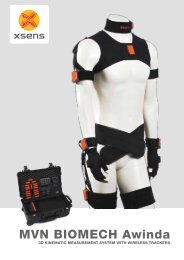
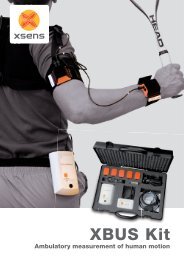
limitati<strong>on</strong>s described above. Xbus kit <str<strong>on</strong>g>based</str<strong>on</strong>g> <strong>on</strong> MTx (<strong>Xsens</strong> Technologies B.V.,<br />
The Netherlands) [11], represented in Figure 1 is an example <str<strong>on</strong>g>of</str<strong>on</strong>g> wearable<br />
<str<strong>on</strong>g>moti<strong>on</strong></str<strong>on</strong>g> <str<strong>on</strong>g>analysis</str<strong>on</strong>g> system which includes <strong>inertial</strong> and magnetic sensors. The<br />
system has small dimensi<strong>on</strong>s; it is completely portable and low cost with<br />
respect to camera-<str<strong>on</strong>g>based</str<strong>on</strong>g> systems.<br />
Figure 1 –Xbus kit from <strong>Xsens</strong> Technologies B.V.<br />
13
Figure 2 shows the working principle at the base <str<strong>on</strong>g>of</str<strong>on</strong>g> the MTx unit. Each MTx<br />
unit c<strong>on</strong>tains a 3D accelerometer, 3D rate <str<strong>on</strong>g>of</str<strong>on</strong>g> turn (gyroscope) and a 3D<br />
magnetometer. By fusing the informati<strong>on</strong> <str<strong>on</strong>g>of</str<strong>on</strong>g> the three different sensors with a<br />
Kalman filter-<str<strong>on</strong>g>based</str<strong>on</strong>g> algorithm (XKF3) the 3D orientati<strong>on</strong> <str<strong>on</strong>g>of</str<strong>on</strong>g> the MTx casing<br />
with respect to a global coordinate system is provided. The global coordinate<br />
system is created using informati<strong>on</strong> from the <strong>inertial</strong> and magnetic sensors.<br />
Figure 2 – working principle <str<strong>on</strong>g>of</str<strong>on</strong>g> MTx <strong>inertial</strong> and magnetic measurement unit<br />
The system described above is not able to provide an estimati<strong>on</strong> <str<strong>on</strong>g>of</str<strong>on</strong>g> the positi<strong>on</strong><br />
<str<strong>on</strong>g>of</str<strong>on</strong>g> the MTx in space, due to vulnerability to integrati<strong>on</strong> drifts, which does not<br />
permit an accurate estimati<strong>on</strong> <str<strong>on</strong>g>of</str<strong>on</strong>g> external or internal anatomical landmarks<br />
positi<strong>on</strong>. Moreover, the presence <str<strong>on</strong>g>of</str<strong>on</strong>g> magnetometers can be a limitati<strong>on</strong> when<br />
the magnetic field in the envir<strong>on</strong>ment becomes n<strong>on</strong> homogeneous, although the<br />
current fusi<strong>on</strong> algorithms are robust to rapid and str<strong>on</strong>g variati<strong>on</strong>s <str<strong>on</strong>g>of</str<strong>on</strong>g> the<br />
magnetic field.<br />
As this thesis will describe, magnetic distorti<strong>on</strong>s due to the presence <str<strong>on</strong>g>of</str<strong>on</strong>g><br />
ferromagnetic materials inside <str<strong>on</strong>g>of</str<strong>on</strong>g> limb prostheses do not allow the use <str<strong>on</strong>g>of</str<strong>on</strong>g><br />
IMMS in certain c<strong>on</strong>diti<strong>on</strong>s, unless special techniques which will be presented.<br />
Recently, <strong>on</strong>ly adopting specific techniques and other systems in parallel it is<br />
possible to have a good estimate <str<strong>on</strong>g>of</str<strong>on</strong>g> positi<strong>on</strong> [12].<br />
As the useful informati<strong>on</strong> provided by each MTx unit, adopting the Xbus kit as<br />
a ubiquitous system, is its orientati<strong>on</strong> in space, the starting point for the<br />
<str<strong>on</strong>g>development</str<strong>on</strong>g> <str<strong>on</strong>g>of</str<strong>on</strong>g> a <str<strong>on</strong>g>moti<strong>on</strong></str<strong>on</strong>g> <str<strong>on</strong>g>analysis</str<strong>on</strong>g> protocol <str<strong>on</strong>g>based</str<strong>on</strong>g> <strong>on</strong> MTx are not marker<br />
trajectories. Furthermore there can be some limitati<strong>on</strong>s about the envir<strong>on</strong>ment<br />
in which the <str<strong>on</strong>g>analysis</str<strong>on</strong>g> can be performed.<br />
The attitude <str<strong>on</strong>g>of</str<strong>on</strong>g> the biomedical community toward MEMS technology, changes<br />
completely with respect to stereophotogrammetry. IMMS open a window into<br />
the new c<strong>on</strong>cept <str<strong>on</strong>g>of</str<strong>on</strong>g> ambulatory <str<strong>on</strong>g>moti<strong>on</strong></str<strong>on</strong>g> <str<strong>on</strong>g>analysis</str<strong>on</strong>g> but at the same time the<br />
evoluti<strong>on</strong> and upgrades in the field <str<strong>on</strong>g>of</str<strong>on</strong>g> <str<strong>on</strong>g>moti<strong>on</strong></str<strong>on</strong>g> capture through <strong>inertial</strong> sensors<br />
characterize theme as ―disc<strong>on</strong>tinuous innovati<strong>on</strong>s‖ [8]. In fact, in this case, the<br />
14
starting point <str<strong>on</strong>g>of</str<strong>on</strong>g> <str<strong>on</strong>g>moti<strong>on</strong></str<strong>on</strong>g> <str<strong>on</strong>g>analysis</str<strong>on</strong>g> <str<strong>on</strong>g>protocols</str<strong>on</strong>g> using <strong>inertial</strong> and magnetic sensors<br />
are not marker trajectories anymore, rather accelerati<strong>on</strong>s, angular velocities,<br />
magnetic field, orientati<strong>on</strong> in space.<br />
Therefore, from <strong>on</strong>e side the high accuracy in tracking the positi<strong>on</strong> <str<strong>on</strong>g>of</str<strong>on</strong>g> markers<br />
does not directly imply an effective <str<strong>on</strong>g>moti<strong>on</strong></str<strong>on</strong>g> <str<strong>on</strong>g>analysis</str<strong>on</strong>g>, being the protocol adopted<br />
and the manual data processing behind playing an important part in it, and due<br />
to the limitati<strong>on</strong>s <str<strong>on</strong>g>of</str<strong>on</strong>g> stereophotogrammetry, some clinical applicati<strong>on</strong>s are not<br />
possible.<br />
On the other side, the <str<strong>on</strong>g>development</str<strong>on</strong>g> <str<strong>on</strong>g>of</str<strong>on</strong>g> portable systems <str<strong>on</strong>g>based</str<strong>on</strong>g> <strong>on</strong> new MEMS<br />
technology, potentially allowing ambulatory <str<strong>on</strong>g>moti<strong>on</strong></str<strong>on</strong>g> <str<strong>on</strong>g>analysis</str<strong>on</strong>g> and simplifying<br />
the data processing, does not imply high accuracy in <str<strong>on</strong>g>moti<strong>on</strong></str<strong>on</strong>g> tracking and<br />
moreover, to be suitable in clinical settings. Again, in fact the protocol to adopt<br />
plays an important role and the specificati<strong>on</strong>s for the design <str<strong>on</strong>g>of</str<strong>on</strong>g> <str<strong>on</strong>g>protocols</str<strong>on</strong>g> for<br />
systems <str<strong>on</strong>g>based</str<strong>on</strong>g> <strong>on</strong> <strong>inertial</strong> and magnetic sensors change radically. In other<br />
words, while for the biomedical community it is comm<strong>on</strong> to adopt<br />
stereophotogrammetry in gait <str<strong>on</strong>g>analysis</str<strong>on</strong>g>, the way in which this can be d<strong>on</strong>e using<br />
<strong>inertial</strong> and magnetic sensors partially needs to be discovered and the relative<br />
knowledge spread am<strong>on</strong>g the community.<br />
1.2.2 Design <str<strong>on</strong>g>of</str<strong>on</strong>g> a <str<strong>on</strong>g>moti<strong>on</strong></str<strong>on</strong>g> <str<strong>on</strong>g>analysis</str<strong>on</strong>g> protocol<br />
A <str<strong>on</strong>g>moti<strong>on</strong></str<strong>on</strong>g> <str<strong>on</strong>g>analysis</str<strong>on</strong>g> protocol is required next to the <str<strong>on</strong>g>moti<strong>on</strong></str<strong>on</strong>g> capture system, being<br />
either <str<strong>on</strong>g>based</str<strong>on</strong>g> <strong>on</strong> stereophotogrammetry or <strong>inertial</strong> sensors. Sometimes, <str<strong>on</strong>g>moti<strong>on</strong></str<strong>on</strong>g><br />
<str<strong>on</strong>g>analysis</str<strong>on</strong>g> <str<strong>on</strong>g>protocols</str<strong>on</strong>g> are created around the instrumentati<strong>on</strong> available at the<br />
moment. This implies that some <str<strong>on</strong>g>of</str<strong>on</strong>g> the features c<strong>on</strong>tained in these <str<strong>on</strong>g>protocols</str<strong>on</strong>g> are<br />
not specificati<strong>on</strong>s <str<strong>on</strong>g>of</str<strong>on</strong>g> a design, therefore not strictly related to their applicati<strong>on</strong>.<br />
As stated in K<strong>on</strong>taxis et al [13], a <str<strong>on</strong>g>moti<strong>on</strong></str<strong>on</strong>g> <str<strong>on</strong>g>analysis</str<strong>on</strong>g> protocol is ―[..] the means <str<strong>on</strong>g>of</str<strong>on</strong>g><br />
measurement <str<strong>on</strong>g>of</str<strong>on</strong>g> the parameters required to test the hypotheses at the base <str<strong>on</strong>g>of</str<strong>on</strong>g><br />
the study research questi<strong>on</strong>‖. This definiti<strong>on</strong> implies that the <str<strong>on</strong>g>development</str<strong>on</strong>g> <str<strong>on</strong>g>of</str<strong>on</strong>g><br />
<str<strong>on</strong>g>moti<strong>on</strong></str<strong>on</strong>g> <str<strong>on</strong>g>analysis</str<strong>on</strong>g> <str<strong>on</strong>g>protocols</str<strong>on</strong>g> should start from the aim <str<strong>on</strong>g>of</str<strong>on</strong>g> its applicati<strong>on</strong>, that is the<br />
research or clinical questi<strong>on</strong>. The better the protocol is designed, the more its<br />
effectiveness. Note that the above definiti<strong>on</strong> does c<strong>on</strong>sider the instrumentati<strong>on</strong><br />
adopted as part <str<strong>on</strong>g>of</str<strong>on</strong>g> it, not out <str<strong>on</strong>g>of</str<strong>on</strong>g> it. Therefore, the choice <str<strong>on</strong>g>of</str<strong>on</strong>g> the instrumentati<strong>on</strong><br />
should be also taken into account when developing <str<strong>on</strong>g>moti<strong>on</strong></str<strong>on</strong>g> <str<strong>on</strong>g>analysis</str<strong>on</strong>g> <str<strong>on</strong>g>protocols</str<strong>on</strong>g>,<br />
especially when the instrumentati<strong>on</strong>s available are <str<strong>on</strong>g>based</str<strong>on</strong>g> <strong>on</strong> different<br />
technologies.<br />
Although the specificati<strong>on</strong>s <str<strong>on</strong>g>of</str<strong>on</strong>g> objectivity and repeatability might be satisfied,<br />
15
instrumental <str<strong>on</strong>g>moti<strong>on</strong></str<strong>on</strong>g> <str<strong>on</strong>g>analysis</str<strong>on</strong>g> does not always meet the requirements <str<strong>on</strong>g>of</str<strong>on</strong>g> a low<br />
cost, and not time-c<strong>on</strong>suming muscolo-skeletal evaluati<strong>on</strong>. This can lead to not<br />
negligible disadvantages from the clinical point <str<strong>on</strong>g>of</str<strong>on</strong>g> view.<br />
In order to improve the efficacy and efficiency <str<strong>on</strong>g>of</str<strong>on</strong>g> the clinical evaluati<strong>on</strong> <str<strong>on</strong>g>based</str<strong>on</strong>g><br />
<strong>on</strong> instrumental <str<strong>on</strong>g>analysis</str<strong>on</strong>g>, it is necessary to find an instrumental tool which can<br />
be suitable in clinical and rehabilitati<strong>on</strong> envir<strong>on</strong>ments, especially when few<br />
resources are available.<br />
The instrumental tool must be defined in relati<strong>on</strong> with the particular impairment<br />
as object <str<strong>on</strong>g>of</str<strong>on</strong>g> the evaluati<strong>on</strong> and the main aim to be achieved. The specificati<strong>on</strong>s<br />
by which a <str<strong>on</strong>g>moti<strong>on</strong></str<strong>on</strong>g> <str<strong>on</strong>g>analysis</str<strong>on</strong>g> protocol must be selected or created corresp<strong>on</strong>d to<br />
some c<strong>on</strong>straints in the clinical settings. Therefore, when designing a protocol<br />
for a specific clinical quest, the following elements must be c<strong>on</strong>sidered:<br />
<br />
<br />
<br />
<br />
<br />
the objectives <str<strong>on</strong>g>of</str<strong>on</strong>g> the <str<strong>on</strong>g>analysis</str<strong>on</strong>g> and the specificati<strong>on</strong>s <str<strong>on</strong>g>of</str<strong>on</strong>g> clinical<br />
procedures;<br />
the c<strong>on</strong>straints and the limitati<strong>on</strong>s due to the envir<strong>on</strong>ment and the<br />
biological system object <str<strong>on</strong>g>of</str<strong>on</strong>g> the study;<br />
the instrumentati<strong>on</strong> available in the market and/or the laboratory;<br />
the numerical quantities to be extracted from the system and necessary<br />
for its descripti<strong>on</strong>;<br />
the error quantities which have to be c<strong>on</strong>sidered during the final<br />
interpretati<strong>on</strong> <str<strong>on</strong>g>of</str<strong>on</strong>g> the data<br />
Using a mathematical language we can assert that the choice <str<strong>on</strong>g>of</str<strong>on</strong>g> a <str<strong>on</strong>g>moti<strong>on</strong></str<strong>on</strong>g><br />
<str<strong>on</strong>g>analysis</str<strong>on</strong>g> protocol corresp<strong>on</strong>ds to the determinati<strong>on</strong> <str<strong>on</strong>g>of</str<strong>on</strong>g> a functi<strong>on</strong> (typically not<br />
linear) depending <strong>on</strong> a certain number <str<strong>on</strong>g>of</str<strong>on</strong>g> parameters which coincides with the<br />
degrees <str<strong>on</strong>g>of</str<strong>on</strong>g> freedom <str<strong>on</strong>g>of</str<strong>on</strong>g> the protocol (the choice <str<strong>on</strong>g>of</str<strong>on</strong>g> the number <str<strong>on</strong>g>of</str<strong>on</strong>g> markers to be<br />
adopted or the durati<strong>on</strong> <str<strong>on</strong>g>of</str<strong>on</strong>g> the <str<strong>on</strong>g>analysis</str<strong>on</strong>g>, for instance). The variability <str<strong>on</strong>g>of</str<strong>on</strong>g> these<br />
parameters corresp<strong>on</strong>ds to the boundary c<strong>on</strong>diti<strong>on</strong>s <str<strong>on</strong>g>of</str<strong>on</strong>g> the mathematical<br />
problem and the range <str<strong>on</strong>g>of</str<strong>on</strong>g> values the parameters can have is defined by the<br />
bioengineer in collaborati<strong>on</strong> with the practiti<strong>on</strong>er, case by case.<br />
The soluti<strong>on</strong> <str<strong>on</strong>g>of</str<strong>on</strong>g> this mathematical problem is therefore the functi<strong>on</strong> such as all<br />
the parameters determining it will have values am<strong>on</strong>g the range <str<strong>on</strong>g>of</str<strong>on</strong>g> variability<br />
permitted.<br />
When no soluti<strong>on</strong> is found, it means that some <str<strong>on</strong>g>of</str<strong>on</strong>g> the c<strong>on</strong>straints <str<strong>on</strong>g>of</str<strong>on</strong>g> the design<br />
are not satisfied and two different scenarios can be c<strong>on</strong>sidered:<br />
1) In the first scenario the protocol selected provides an overestimati<strong>on</strong> <str<strong>on</strong>g>of</str<strong>on</strong>g> the<br />
16
quantitative informati<strong>on</strong> required as output <str<strong>on</strong>g>of</str<strong>on</strong>g> its applicati<strong>on</strong>. This is the case <str<strong>on</strong>g>of</str<strong>on</strong>g><br />
a protocol not easily applicable in clinical settings, for example a protocol with<br />
a great amount <str<strong>on</strong>g>of</str<strong>on</strong>g> data as output providing results too difficult to be interpreted<br />
and adopted for diagnostic or therapeutic purposes. In this case, all the<br />
resources adopted for obtaining results with high accuracy do not increase the<br />
benefit-cost ratio.<br />
2) The sec<strong>on</strong>d scenario is opposite to the first. The values assumed by the<br />
parameters lead to an underestimati<strong>on</strong> <str<strong>on</strong>g>of</str<strong>on</strong>g> the informati<strong>on</strong> required as output <str<strong>on</strong>g>of</str<strong>on</strong>g><br />
the applicati<strong>on</strong>. As a c<strong>on</strong>sequence the results can be incorrect and with low<br />
applicability in the clinical diagnosis or clinical decisi<strong>on</strong>-making process.<br />
When a soluti<strong>on</strong> is found, the protocol is suitable for the specific instrumental<br />
<str<strong>on</strong>g>analysis</str<strong>on</strong>g>, although the soluti<strong>on</strong> is not necessarily unique.<br />
In summary, the design <str<strong>on</strong>g>of</str<strong>on</strong>g> a <str<strong>on</strong>g>moti<strong>on</strong></str<strong>on</strong>g> <str<strong>on</strong>g>analysis</str<strong>on</strong>g> protocol must take into account<br />
the available instrumentati<strong>on</strong>/technology, the specificati<strong>on</strong>s deriving from the<br />
research/clinical questi<strong>on</strong> and elements supporting its reliability and<br />
effectiveness.<br />
1.2.3 Design <str<strong>on</strong>g>of</str<strong>on</strong>g> a <str<strong>on</strong>g>moti<strong>on</strong></str<strong>on</strong>g> <str<strong>on</strong>g>analysis</str<strong>on</strong>g> protocol <str<strong>on</strong>g>based</str<strong>on</strong>g> <strong>on</strong> <strong>inertial</strong> sensors<br />
In the case <str<strong>on</strong>g>of</str<strong>on</strong>g> MEMS technology, in particular IMMS, their combined use by<br />
means <str<strong>on</strong>g>of</str<strong>on</strong>g> optimizati<strong>on</strong> algorithms (Chapter 6), allow the measurement <str<strong>on</strong>g>of</str<strong>on</strong>g> the<br />
orientati<strong>on</strong> <str<strong>on</strong>g>of</str<strong>on</strong>g> body segments and, through specific techniques [12], the<br />
measurement <str<strong>on</strong>g>of</str<strong>on</strong>g> their positi<strong>on</strong>, although without the combined use <str<strong>on</strong>g>of</str<strong>on</strong>g> other<br />
instrumentati<strong>on</strong>s the accuracy is not comparable with the <strong>on</strong>e <str<strong>on</strong>g>of</str<strong>on</strong>g><br />
stereophotogrammetric systems. The manual interventi<strong>on</strong> <str<strong>on</strong>g>of</str<strong>on</strong>g> the user is<br />
therefore shifted from the data processing <str<strong>on</strong>g>of</str<strong>on</strong>g> marker trajectories, with<br />
stereophotogrammetry, to the next steps: to validate the accuracy in the<br />
estimati<strong>on</strong> <str<strong>on</strong>g>of</str<strong>on</strong>g> positi<strong>on</strong> and orientati<strong>on</strong> and to extract valuable and meaningful<br />
clinical informati<strong>on</strong> from repeatable and reliable measurements.<br />
These steps are required when using all kind <str<strong>on</strong>g>of</str<strong>on</strong>g> technology. However, being<br />
<str<strong>on</strong>g>moti<strong>on</strong></str<strong>on</strong>g> capture systems <str<strong>on</strong>g>based</str<strong>on</strong>g> <strong>on</strong> <strong>inertial</strong> sensors more recent than the <strong>on</strong>es<br />
<str<strong>on</strong>g>based</str<strong>on</strong>g> <strong>on</strong> stereophotogrammetry, the knowledge available about methods to<br />
perform the above steps is limited when comparing it with golden standard<br />
systems.<br />
The positi<strong>on</strong>ing <str<strong>on</strong>g>of</str<strong>on</strong>g> markers <strong>on</strong> the body segments and s<str<strong>on</strong>g>of</str<strong>on</strong>g>t tissue artefact<br />
reducti<strong>on</strong> techniques are example <str<strong>on</strong>g>of</str<strong>on</strong>g> methodologies developed during the past<br />
17
years using stereophotogrammetric systems and that can be applied when<br />
developing a <str<strong>on</strong>g>moti<strong>on</strong></str<strong>on</strong>g> <str<strong>on</strong>g>analysis</str<strong>on</strong>g> protocol <str<strong>on</strong>g>based</str<strong>on</strong>g> <strong>on</strong> IMMS.<br />
There are several aspects to c<strong>on</strong>sider when developing <str<strong>on</strong>g>moti<strong>on</strong></str<strong>on</strong>g> capture systems<br />
<str<strong>on</strong>g>based</str<strong>on</strong>g> <strong>on</strong> IMMS.<br />
Firstly, not all the methodology developed in the past years using systems<br />
<str<strong>on</strong>g>based</str<strong>on</strong>g> <strong>on</strong> stereophotogrammetry, can be directly applied when using IMMS.<br />
For instance, anatomical calibrati<strong>on</strong>s <str<strong>on</strong>g>based</str<strong>on</strong>g> <strong>on</strong> anatomical landmark palpati<strong>on</strong><br />
are not possible when the system cannot provide an accurate estimati<strong>on</strong> <str<strong>on</strong>g>of</str<strong>on</strong>g><br />
external landmarks.<br />
Sec<strong>on</strong>dly, the <str<strong>on</strong>g>development</str<strong>on</strong>g> <str<strong>on</strong>g>of</str<strong>on</strong>g> <str<strong>on</strong>g>moti<strong>on</strong></str<strong>on</strong>g> <str<strong>on</strong>g>analysis</str<strong>on</strong>g> <str<strong>on</strong>g>protocols</str<strong>on</strong>g> <str<strong>on</strong>g>based</str<strong>on</strong>g> <strong>on</strong> IMMS<br />
naturally walks in parallel with the main advantage <str<strong>on</strong>g>of</str<strong>on</strong>g> having a portable<br />
system: to provide a ubiquitous <str<strong>on</strong>g>moti<strong>on</strong></str<strong>on</strong>g> <str<strong>on</strong>g>analysis</str<strong>on</strong>g> system. This augments the<br />
number <str<strong>on</strong>g>of</str<strong>on</strong>g> protocol specificati<strong>on</strong>s when using portable systems, with<br />
requirements different than stereophotogrammetric systems <strong>on</strong>es. This means<br />
that some methodologies which are required when using systems <str<strong>on</strong>g>based</str<strong>on</strong>g> <strong>on</strong><br />
<strong>inertial</strong> and magnetic sensors can be developed and validated using the<br />
stereophotogrammetric systems (e.g. functi<strong>on</strong>al methods), but the evaluati<strong>on</strong> <str<strong>on</strong>g>of</str<strong>on</strong>g><br />
a portable system, providing an ubiquitous <str<strong>on</strong>g>analysis</str<strong>on</strong>g>, is not always possible<br />
inside <str<strong>on</strong>g>of</str<strong>on</strong>g> a laboratory.<br />
In general we can assert that <str<strong>on</strong>g>protocols</str<strong>on</strong>g> <str<strong>on</strong>g>based</str<strong>on</strong>g> <strong>on</strong> IMMS are the tool by which<br />
new methodologies developed for being compatible with the new technology,<br />
are applied to specific questi<strong>on</strong>s.<br />
Furthermore, the correct design <str<strong>on</strong>g>of</str<strong>on</strong>g> the protocol is not the unique step to perform<br />
when creating a <str<strong>on</strong>g>moti<strong>on</strong></str<strong>on</strong>g> <str<strong>on</strong>g>analysis</str<strong>on</strong>g> system. In fact, in order to provide quantitative<br />
measures for supporting the clinicians in better understanding pathology or in<br />
the decisi<strong>on</strong>-making process, all the measurements must be repeatable and<br />
validated. The last two are indeed important requirements for all the<br />
methodologies and <str<strong>on</strong>g>protocols</str<strong>on</strong>g> developed, in order to be shared am<strong>on</strong>g the<br />
community and finally adopted in practice.<br />
Starting from the above c<strong>on</strong>siderati<strong>on</strong>s it is useful to c<strong>on</strong>sider the golden<br />
standard systems as the starting point for the <str<strong>on</strong>g>development</str<strong>on</strong>g> and improvement <str<strong>on</strong>g>of</str<strong>on</strong>g><br />
<str<strong>on</strong>g>moti<strong>on</strong></str<strong>on</strong>g> <str<strong>on</strong>g>analysis</str<strong>on</strong>g> <str<strong>on</strong>g>protocols</str<strong>on</strong>g> <str<strong>on</strong>g>based</str<strong>on</strong>g> <strong>on</strong> IMMS.<br />
From <strong>on</strong>e side, there is the need to apply valid and reliable methods using<br />
18
stereophotogrammetry for evaluating the accuracy and precisi<strong>on</strong> <str<strong>on</strong>g>of</str<strong>on</strong>g> systems<br />
<str<strong>on</strong>g>based</str<strong>on</strong>g> <strong>on</strong> new technology (such as MEMS <strong>inertial</strong> and magnetic sensors).<br />
From the other side, novel methodologies must be developed for using IMMS,<br />
due to specificati<strong>on</strong>s in the protocol design which do not come from the<br />
experience with stereophotogrammetry.<br />
Finally, the validati<strong>on</strong> <str<strong>on</strong>g>of</str<strong>on</strong>g> <str<strong>on</strong>g>protocols</str<strong>on</strong>g> <str<strong>on</strong>g>based</str<strong>on</strong>g> <strong>on</strong> IMMS, in terms <str<strong>on</strong>g>of</str<strong>on</strong>g> their capability<br />
in providing clinically meaningful informati<strong>on</strong>, is a needful step for the<br />
introducti<strong>on</strong> <str<strong>on</strong>g>of</str<strong>on</strong>g> these tools into the biomedical and clinical community.<br />
19
1.3 INAIL Prostheses Centre<br />
The clinical questi<strong>on</strong>s at INAIL Prostheses Centre were the main motivati<strong>on</strong> at<br />
the base <str<strong>on</strong>g>of</str<strong>on</strong>g> this thesis. INAIL is the Italian workers‘ compensati<strong>on</strong> authority,<br />
―not just compensati<strong>on</strong> but a global protecti<strong>on</strong> system for all workers‖.<br />
INAIL has three main goals:<br />
1) the preventi<strong>on</strong> <str<strong>on</strong>g>of</str<strong>on</strong>g> work-related injuries;<br />
2) to provide the injured workers with adequate medical treatments and<br />
ec<strong>on</strong>omic benefits,<br />
3) to return them to active and participated social and working life.<br />
Table 1 - INAIL statistics about work-related injuries in Italy<br />
Table 1 presents a recent summary (DATI INAIL, number 11, 2009) <str<strong>on</strong>g>of</str<strong>on</strong>g> workrelated<br />
injuries (including injuries occurring while moving from house to work<br />
and vice versa) occurred during the last half <str<strong>on</strong>g>of</str<strong>on</strong>g> 2008 and the first half <str<strong>on</strong>g>of</str<strong>on</strong>g> 2009.<br />
Most <str<strong>on</strong>g>of</str<strong>on</strong>g> the injuries occur during ordinary work (which means not during work<br />
which takes place outside the building). Although decreasing from 2008 to<br />
2009, the number <str<strong>on</strong>g>of</str<strong>on</strong>g> injuries is still impressive.<br />
INAIL services are provided through the work <str<strong>on</strong>g>of</str<strong>on</strong>g> 235 local <str<strong>on</strong>g>of</str<strong>on</strong>g>fices <strong>on</strong> the<br />
Italian territory.<br />
In particular, INAIL Prostheses Centre provides INAIL services as centre for<br />
the experimentati<strong>on</strong> and applicati<strong>on</strong> <str<strong>on</strong>g>of</str<strong>on</strong>g> prostheses and orthopaedic devices, by<br />
20
searching for new technologies to be introduced in the producti<strong>on</strong> <str<strong>on</strong>g>of</str<strong>on</strong>g><br />
comp<strong>on</strong>ents, by producing and providing patients with new prostheses and<br />
orthopaedic devices, by c<strong>on</strong>trolling the steps <str<strong>on</strong>g>of</str<strong>on</strong>g> the rehabilitati<strong>on</strong> process.<br />
The criteria for the work reintegrati<strong>on</strong> are <str<strong>on</strong>g>based</str<strong>on</strong>g> <strong>on</strong> the correct assessment <str<strong>on</strong>g>of</str<strong>on</strong>g><br />
the level <str<strong>on</strong>g>of</str<strong>on</strong>g> disability and the working potentiality. From the ec<strong>on</strong>omical and<br />
social points <str<strong>on</strong>g>of</str<strong>on</strong>g> view, in order to achieve the above goals, the main objectives<br />
are to quantitatively and objectively evaluate the impairment <str<strong>on</strong>g>of</str<strong>on</strong>g> patients with<br />
work-related injuries, the ability in c<strong>on</strong>trolling their prosthetic devices and the<br />
<str<strong>on</strong>g>development</str<strong>on</strong>g> <str<strong>on</strong>g>of</str<strong>on</strong>g> new prosthetic<br />
devices.<br />
At INAIL Prostheses Centre the<br />
rehabilitati<strong>on</strong> process is <str<strong>on</strong>g>based</str<strong>on</strong>g> <strong>on</strong><br />
a multi-disciplinary team<br />
approach to solve the clinical<br />
questi<strong>on</strong> [ 14 ].<br />
These objectives can be reached<br />
through systems that support the<br />
physiotherapist in the clinical<br />
decisi<strong>on</strong>s and guide him during<br />
the rehabilitati<strong>on</strong>.<br />
In general, clinicians need to be<br />
supported in the same place the<br />
rehabilitati<strong>on</strong> treatment is<br />
Figure 3 – INAIL Prostheses Centre<br />
Vigorso di Budrio (BO), Italy<br />
21<br />
performed, with fast and accurate<br />
measurements with ambulatory<br />
systems, fast and reliable<br />
<str<strong>on</strong>g>protocols</str<strong>on</strong>g> for measuring the mobility and the activities <str<strong>on</strong>g>of</str<strong>on</strong>g> the daily living.<br />
When these kinds <str<strong>on</strong>g>of</str<strong>on</strong>g> systems will be available, INAIL local <str<strong>on</strong>g>of</str<strong>on</strong>g>fices will be able<br />
to m<strong>on</strong>itor the evoluti<strong>on</strong> <str<strong>on</strong>g>of</str<strong>on</strong>g> patients‘ motor ability over time and the<br />
orthopaedic technicians will evaluate whether the patient is correctly learning<br />
how to c<strong>on</strong>trol his own prosthesis.<br />
As previously described, despite <str<strong>on</strong>g>of</str<strong>on</strong>g> the good results in terms <str<strong>on</strong>g>of</str<strong>on</strong>g> measurement<br />
accuracy and applicability, <str<strong>on</strong>g>protocols</str<strong>on</strong>g> <str<strong>on</strong>g>based</str<strong>on</strong>g> <strong>on</strong> stereophotogrammetry cannot be<br />
easily adopted in the clinical settings above described. A possible soluti<strong>on</strong> to<br />
these limitati<strong>on</strong>s comes from IMMS.<br />
In order to achieve the above objectives the <str<strong>on</strong>g>development</str<strong>on</strong>g> <str<strong>on</strong>g>of</str<strong>on</strong>g> <str<strong>on</strong>g>moti<strong>on</strong></str<strong>on</strong>g> <str<strong>on</strong>g>analysis</str<strong>on</strong>g><br />
<str<strong>on</strong>g>protocols</str<strong>on</strong>g> <str<strong>on</strong>g>based</str<strong>on</strong>g> <strong>on</strong> IMMs, overcoming the limitati<strong>on</strong>s <str<strong>on</strong>g>of</str<strong>on</strong>g> the systems <str<strong>on</strong>g>based</str<strong>on</strong>g> <strong>on</strong>
stereophotogrammetry, required that:<br />
1) the <str<strong>on</strong>g>moti<strong>on</strong></str<strong>on</strong>g> <str<strong>on</strong>g>analysis</str<strong>on</strong>g> <str<strong>on</strong>g>protocols</str<strong>on</strong>g> <str<strong>on</strong>g>based</str<strong>on</strong>g> <strong>on</strong> stereophotogrammetry, already<br />
adopted at INAIL Prostheses Centre, were improved for being applied<br />
to specific applicati<strong>on</strong>s, such as shoulder pathologies;<br />
2) to start multicenter trials <strong>on</strong> the applicati<strong>on</strong> <str<strong>on</strong>g>of</str<strong>on</strong>g> the above <str<strong>on</strong>g>protocols</str<strong>on</strong>g> for<br />
exploring their validity not <strong>on</strong>ly in the research field but also in the<br />
routine clinical examinati<strong>on</strong>.<br />
3) to develop new methodologies, algorithms and s<str<strong>on</strong>g>of</str<strong>on</strong>g>tware for supporting<br />
the validati<strong>on</strong> <str<strong>on</strong>g>of</str<strong>on</strong>g> the <str<strong>on</strong>g>protocols</str<strong>on</strong>g> <str<strong>on</strong>g>based</str<strong>on</strong>g> <strong>on</strong> stereophotogrammetry, taking<br />
in c<strong>on</strong>siderati<strong>on</strong> the later need <str<strong>on</strong>g>of</str<strong>on</strong>g> validating <str<strong>on</strong>g>protocols</str<strong>on</strong>g> <str<strong>on</strong>g>based</str<strong>on</strong>g> <strong>on</strong> <strong>inertial</strong><br />
sensors.<br />
INAIL Prostheses Centre was provided with a Vic<strong>on</strong> MX4 system with 6<br />
infrared cameras (Oxford Metrics, UK), two force plates (Kistler Instrumente<br />
AG, Switzerland), as instrumentati<strong>on</strong> for upper and lower limb <str<strong>on</strong>g>moti<strong>on</strong></str<strong>on</strong>g> <str<strong>on</strong>g>analysis</str<strong>on</strong>g><br />
using stereophotogrammetry.<br />
The <strong>inertial</strong> and magnetic measurement system adopted for ambulatory <str<strong>on</strong>g>analysis</str<strong>on</strong>g><br />
was the Xbus Kit <str<strong>on</strong>g>based</str<strong>on</strong>g> <strong>on</strong> MTx, previously cited. Further descripti<strong>on</strong> <str<strong>on</strong>g>of</str<strong>on</strong>g> this<br />
system can be found in the next secti<strong>on</strong>s.<br />
22
1.4 Aim <str<strong>on</strong>g>of</str<strong>on</strong>g> the thesis and framework<br />
Starting from the INAIL needs previously described, the main goal <str<strong>on</strong>g>of</str<strong>on</strong>g> this<br />
thesis was the <str<strong>on</strong>g>development</str<strong>on</strong>g> <str<strong>on</strong>g>of</str<strong>on</strong>g> <str<strong>on</strong>g>moti<strong>on</strong></str<strong>on</strong>g> <str<strong>on</strong>g>analysis</str<strong>on</strong>g> <str<strong>on</strong>g>protocols</str<strong>on</strong>g> <str<strong>on</strong>g>based</str<strong>on</strong>g> <strong>on</strong> IMMS, for<br />
upper and lower extremities applicati<strong>on</strong>.<br />
This goal was achieved from <strong>on</strong>e side trying to correctly design the <str<strong>on</strong>g>protocols</str<strong>on</strong>g><br />
<str<strong>on</strong>g>based</str<strong>on</strong>g> <strong>on</strong> <strong>inertial</strong> sensors, in terms <str<strong>on</strong>g>of</str<strong>on</strong>g> exploring and developing which features<br />
were suitable for the specific applicati<strong>on</strong> <str<strong>on</strong>g>of</str<strong>on</strong>g> the <str<strong>on</strong>g>protocols</str<strong>on</strong>g>.<br />
From the other side, despite <str<strong>on</strong>g>of</str<strong>on</strong>g> the limitati<strong>on</strong>s <str<strong>on</strong>g>of</str<strong>on</strong>g> the optoelectr<strong>on</strong>ic systems,<br />
their use was necessary because:<br />
1) they provided a gold standard and accurate measurement, which was used as<br />
reference for the validati<strong>on</strong> <str<strong>on</strong>g>of</str<strong>on</strong>g> the <str<strong>on</strong>g>protocols</str<strong>on</strong>g> <str<strong>on</strong>g>based</str<strong>on</strong>g> <strong>on</strong> <strong>inertial</strong> sensors.<br />
2) all the basic knowledge needful for the creati<strong>on</strong> <str<strong>on</strong>g>of</str<strong>on</strong>g> a <str<strong>on</strong>g>moti<strong>on</strong></str<strong>on</strong>g> <str<strong>on</strong>g>analysis</str<strong>on</strong>g> protocol<br />
(e.g. s<str<strong>on</strong>g>of</str<strong>on</strong>g>t tissue artefact, positi<strong>on</strong>ing <str<strong>on</strong>g>of</str<strong>on</strong>g> markers), created by the community in<br />
the past 50 years, was the starting point for the generati<strong>on</strong> <str<strong>on</strong>g>of</str<strong>on</strong>g> the same kind <str<strong>on</strong>g>of</str<strong>on</strong>g><br />
knowledge in the case <str<strong>on</strong>g>of</str<strong>on</strong>g> <strong>inertial</strong> sensors.<br />
As this thesis will dem<strong>on</strong>strate, the two worlds <str<strong>on</strong>g>of</str<strong>on</strong>g> instrumentati<strong>on</strong>, systems<br />
<str<strong>on</strong>g>based</str<strong>on</strong>g> <strong>on</strong> stereophotogrammetry <strong>on</strong> <strong>on</strong>e side, and <strong>inertial</strong> and magnetic sensors<br />
<strong>on</strong> the other side, were able to exist side by side and moreover this thesis will<br />
show how <str<strong>on</strong>g>protocols</str<strong>on</strong>g> developed starting from these instrumentati<strong>on</strong>s can be<br />
complementary, depending <strong>on</strong> the clinical applicati<strong>on</strong>.<br />
Therefore this thesis will describe the <str<strong>on</strong>g>development</str<strong>on</strong>g> <str<strong>on</strong>g>of</str<strong>on</strong>g> <str<strong>on</strong>g>moti<strong>on</strong></str<strong>on</strong>g> <str<strong>on</strong>g>analysis</str<strong>on</strong>g><br />
<str<strong>on</strong>g>protocols</str<strong>on</strong>g>, <str<strong>on</strong>g>based</str<strong>on</strong>g> <strong>on</strong> <strong>inertial</strong> sensors, for clinical applicati<strong>on</strong>s <strong>on</strong> upper and lower<br />
extremities pathologies (hereinafter called UX and LX), starting from the gold<br />
standard <str<strong>on</strong>g>moti<strong>on</strong></str<strong>on</strong>g> <str<strong>on</strong>g>analysis</str<strong>on</strong>g> performed through the optoelectr<strong>on</strong>ic systems,<br />
adopting and developing comm<strong>on</strong> methodologies in terms <str<strong>on</strong>g>of</str<strong>on</strong>g> methods for the<br />
<str<strong>on</strong>g>protocols</str<strong>on</strong>g> validati<strong>on</strong>, data <str<strong>on</strong>g>analysis</str<strong>on</strong>g>, algorithms and s<str<strong>on</strong>g>of</str<strong>on</strong>g>tware. Moreover, the<br />
<str<strong>on</strong>g>development</str<strong>on</strong>g> <str<strong>on</strong>g>of</str<strong>on</strong>g> <str<strong>on</strong>g>protocols</str<strong>on</strong>g> must take into account the fact that, for each<br />
applicati<strong>on</strong>, <str<strong>on</strong>g>protocols</str<strong>on</strong>g> <str<strong>on</strong>g>based</str<strong>on</strong>g> <strong>on</strong> <strong>inertial</strong> and magnetic sensors and <str<strong>on</strong>g>protocols</str<strong>on</strong>g><br />
<str<strong>on</strong>g>based</str<strong>on</strong>g> <strong>on</strong> stereophotogrammetry should be able to measure the same level <str<strong>on</strong>g>of</str<strong>on</strong>g><br />
impairment.<br />
This thesis was almost entirely carried out at the INAIL Prostheses Centre, with<br />
the collaborati<strong>on</strong> <str<strong>on</strong>g>of</str<strong>on</strong>g> the Department <str<strong>on</strong>g>of</str<strong>on</strong>g> Electr<strong>on</strong>ics, Computer Science and<br />
Systems (Bologna, Italy) and <strong>Xsens</strong> Technologies B.V. (Enschede, The<br />
23
Netherlands).<br />
In order to achieve the goal described above, the main objectives were:<br />
1) to support the creati<strong>on</strong> and to perform the validati<strong>on</strong> <str<strong>on</strong>g>of</str<strong>on</strong>g> a protocol<br />
<str<strong>on</strong>g>based</str<strong>on</strong>g> <strong>on</strong> <strong>inertial</strong> sensors for patients with shoulder pathologies like<br />
rotator-cuff tears and shoulder instability;<br />
2) to support the creati<strong>on</strong> and validati<strong>on</strong> <str<strong>on</strong>g>of</str<strong>on</strong>g> a gait <str<strong>on</strong>g>analysis</str<strong>on</strong>g> protocol <str<strong>on</strong>g>based</str<strong>on</strong>g><br />
<strong>on</strong> <strong>inertial</strong> sensors specifically designed for amputees;<br />
3) to validate the use <str<strong>on</strong>g>of</str<strong>on</strong>g> a new method for applying the protocol in 1) to<br />
subjects with lower limb amputati<strong>on</strong>;<br />
4) to develop s<str<strong>on</strong>g>of</str<strong>on</strong>g>tware for supporting the validati<strong>on</strong> <str<strong>on</strong>g>of</str<strong>on</strong>g> the <str<strong>on</strong>g>protocols</str<strong>on</strong>g><br />
<str<strong>on</strong>g>based</str<strong>on</strong>g> <strong>on</strong> <strong>inertial</strong> sensors and to transform them into end-user clinical<br />
s<str<strong>on</strong>g>of</str<strong>on</strong>g>tware which can simplify the applicati<strong>on</strong> <str<strong>on</strong>g>of</str<strong>on</strong>g> all the above <str<strong>on</strong>g>protocols</str<strong>on</strong>g><br />
in clinical settings.<br />
The framework adopted during the 3-years research is schematized in Figure 4.<br />
Figure 4 – Framework adopted during the <str<strong>on</strong>g>development</str<strong>on</strong>g> <str<strong>on</strong>g>of</str<strong>on</strong>g> <str<strong>on</strong>g>moti<strong>on</strong></str<strong>on</strong>g> <str<strong>on</strong>g>analysis</str<strong>on</strong>g> <str<strong>on</strong>g>protocols</str<strong>on</strong>g> <str<strong>on</strong>g>based</str<strong>on</strong>g> <strong>on</strong><br />
<strong>inertial</strong> sensors<br />
24
During the first year <str<strong>on</strong>g>of</str<strong>on</strong>g> research, the <str<strong>on</strong>g>moti<strong>on</strong></str<strong>on</strong>g> <str<strong>on</strong>g>analysis</str<strong>on</strong>g> protocol <str<strong>on</strong>g>based</str<strong>on</strong>g> <strong>on</strong><br />
stereophotogrammetry, developed for the functi<strong>on</strong>al assessment <str<strong>on</strong>g>of</str<strong>on</strong>g> UX <strong>on</strong><br />
patients with shoulder pathologies, was completed and extended for the<br />
applicati<strong>on</strong>s <strong>on</strong> trans-humeral amputees. This work was published in [15].<br />
Moreover, the need to study LX kinematics <str<strong>on</strong>g>of</str<strong>on</strong>g> amputees during gait required to<br />
provide INAIL with the s<str<strong>on</strong>g>of</str<strong>on</strong>g>tware tools for the applicati<strong>on</strong> <str<strong>on</strong>g>of</str<strong>on</strong>g> the CAST [16]<br />
technique and the <str<strong>on</strong>g>development</str<strong>on</strong>g> <str<strong>on</strong>g>of</str<strong>on</strong>g> a specific protocol for transfemoral<br />
amputees. This part was already presented during c<strong>on</strong>ferences in 2009 and it<br />
was included in the full paper submitted to an internati<strong>on</strong>al journal [17] .<br />
UX and LX studies shared CAST, algorithms and s<str<strong>on</strong>g>of</str<strong>on</strong>g>tware (UpLiFE and<br />
LoLiFE toolboxes). In the same year, some preliminary studies <strong>on</strong> UX and LX<br />
<str<strong>on</strong>g>protocols</str<strong>on</strong>g> <str<strong>on</strong>g>based</str<strong>on</strong>g> <strong>on</strong> <strong>inertial</strong> sensors were performed.<br />
During the sec<strong>on</strong>d year, the intra and inter operator repeatability study <str<strong>on</strong>g>of</str<strong>on</strong>g> the<br />
protocol <str<strong>on</strong>g>based</str<strong>on</strong>g> <strong>on</strong> stereophotogrammetry for applicati<strong>on</strong>s <strong>on</strong> UX was carried<br />
out [18] and the necessary data required for the repeatability study <str<strong>on</strong>g>of</str<strong>on</strong>g> the<br />
protocol <str<strong>on</strong>g>based</str<strong>on</strong>g> <strong>on</strong> IMMS for applicati<strong>on</strong> <strong>on</strong> scapula tracking and <strong>on</strong> lower limb<br />
amputees were acquired.<br />
The methodology developed for the <str<strong>on</strong>g>protocols</str<strong>on</strong>g> <str<strong>on</strong>g>based</str<strong>on</strong>g> <strong>on</strong> stereophotogrammetry<br />
was adopted for the experiments using <strong>inertial</strong> sensors. During the last year <str<strong>on</strong>g>of</str<strong>on</strong>g><br />
research, the validati<strong>on</strong> <str<strong>on</strong>g>of</str<strong>on</strong>g> the <str<strong>on</strong>g>protocols</str<strong>on</strong>g> <str<strong>on</strong>g>based</str<strong>on</strong>g> <strong>on</strong> IMMS was carried out for<br />
applicati<strong>on</strong>s <strong>on</strong> UX [19], and during the experience abroad at <strong>Xsens</strong><br />
Technologies B.V. a new methodology for developing the protocol for aboveknee<br />
amputees kinematics through the MTx system was tested and validated.<br />
This work was submitted to the ISPO 2010 c<strong>on</strong>ference (Leipzig, Germany) and<br />
was accepted as oral presentati<strong>on</strong>. A full paper is going to be finalized.<br />
The final step for the <str<strong>on</strong>g>protocols</str<strong>on</strong>g> developed during the past years was to create<br />
the end-user clinical s<str<strong>on</strong>g>of</str<strong>on</strong>g>tware for their applicati<strong>on</strong> in clinical settings [20] .<br />
Finally, the protocol <str<strong>on</strong>g>based</str<strong>on</strong>g> <strong>on</strong> stereophotogrammetry for the evaluati<strong>on</strong> <str<strong>on</strong>g>of</str<strong>on</strong>g><br />
amputees‘ kinematics was adopted together with a kinetic model, in order to<br />
compare the calculati<strong>on</strong> <str<strong>on</strong>g>of</str<strong>on</strong>g> lower limb 3D joint moments in gait <str<strong>on</strong>g>analysis</str<strong>on</strong>g><br />
obtained through two alternative methods: inverse dynamics (<str<strong>on</strong>g>based</str<strong>on</strong>g> <strong>on</strong> Newt<strong>on</strong>-<br />
Euler mechanics) and Ground Reacti<strong>on</strong> Force Vector approach [21]. Two case<br />
studies <strong>on</strong> transfemoral and transtibial amputees were reported [22].<br />
25
1.5 Experience at <strong>Xsens</strong> Technologies B.V.<br />
Figure 5 – <strong>Xsens</strong><br />
Technologies B.V.<br />
The last year <str<strong>on</strong>g>of</str<strong>on</strong>g> research was almost entirely spent at<br />
<strong>Xsens</strong> Technologies B.V. (Enschede The<br />
Netherlands). Founded in 2000, <strong>Xsens</strong> Technologies is<br />
market leader in miniature 3D tracking <str<strong>on</strong>g>based</str<strong>on</strong>g> <strong>on</strong><br />
MEMS technology. By their experience and unique<br />
intellectual property in the field <str<strong>on</strong>g>of</str<strong>on</strong>g> multi-sensor data<br />
fusi<strong>on</strong> algorithms, <strong>Xsens</strong> produces innovative products<br />
which have been also adopted during the past years for<br />
applied research in the movement science field [23-<br />
26]. <strong>Xsens</strong> Technologies is the producer <str<strong>on</strong>g>of</str<strong>on</strong>g> the IMMS<br />
<str<strong>on</strong>g>based</str<strong>on</strong>g> <strong>on</strong> MTx adopted in the experiments for the<br />
<str<strong>on</strong>g>protocols</str<strong>on</strong>g> <str<strong>on</strong>g>based</str<strong>on</strong>g> <strong>on</strong> <strong>inertial</strong> sensors at INAIL Prostheses<br />
Centre.<br />
The l<strong>on</strong>g experience at <strong>Xsens</strong> Technology was necessary in order to:<br />
1) improve the knowledge about IMMs and related algorithms for estimating<br />
orientati<strong>on</strong> in space;<br />
2) extend the UX and LX <str<strong>on</strong>g>protocols</str<strong>on</strong>g> <str<strong>on</strong>g>based</str<strong>on</strong>g> <strong>on</strong> IMMS, validated for applicati<strong>on</strong>s<br />
<strong>on</strong> healthy subjects so that they could be applied <strong>on</strong> amputees, where the<br />
presence <str<strong>on</strong>g>of</str<strong>on</strong>g> ferromagnetic materials influenced the measurement and studying<br />
in which c<strong>on</strong>diti<strong>on</strong>s they can result critical;<br />
3) improve the s<str<strong>on</strong>g>of</str<strong>on</strong>g>tware developed at INAIL Prostheses Centre, according to<br />
the new algorithms and capabilities <str<strong>on</strong>g>of</str<strong>on</strong>g>fered by the S<str<strong>on</strong>g>of</str<strong>on</strong>g>tware Development Kit<br />
by <strong>Xsens</strong>;<br />
4) simplify the executi<strong>on</strong> <str<strong>on</strong>g>of</str<strong>on</strong>g> the experiments aiming to validate the <str<strong>on</strong>g>protocols</str<strong>on</strong>g>, in<br />
terms <str<strong>on</strong>g>of</str<strong>on</strong>g> synchr<strong>on</strong>izati<strong>on</strong> between different measurement systems and spotchecks<br />
<strong>on</strong> the quality <str<strong>on</strong>g>of</str<strong>on</strong>g> the data provided by the IMMS;<br />
5) understand how the <str<strong>on</strong>g>protocols</str<strong>on</strong>g> developed at INAIL Prostheses Centre could<br />
be optimized for specific UX and LX applicati<strong>on</strong>s, such as gait <str<strong>on</strong>g>analysis</str<strong>on</strong>g> <str<strong>on</strong>g>of</str<strong>on</strong>g><br />
transfemoral and transtibial amputees, in clinical settings;<br />
6) work in c<strong>on</strong>tact with the industrial envir<strong>on</strong>ment in c<strong>on</strong>necti<strong>on</strong> with dutch and<br />
26
italian researchers for creating clinical applicati<strong>on</strong>s <str<strong>on</strong>g>of</str<strong>on</strong>g> IMMS.<br />
27
1.6 Thesis outline<br />
In the research project both optoelectr<strong>on</strong>ic systems and <strong>inertial</strong> sensors were<br />
adopted as instrumentati<strong>on</strong> and both UX and LX were c<strong>on</strong>sidered as targets <str<strong>on</strong>g>of</str<strong>on</strong>g><br />
the <str<strong>on</strong>g>protocols</str<strong>on</strong>g>. Comm<strong>on</strong> methodology is applied depending <strong>on</strong> the specific<br />
applicati<strong>on</strong>.<br />
For this reas<strong>on</strong> the thesis is divided into 5 main areas. The general introducti<strong>on</strong><br />
(Chapter 1), UX (Chapter 2) and LX (Chapter 3) <str<strong>on</strong>g>protocols</str<strong>on</strong>g> <str<strong>on</strong>g>based</str<strong>on</strong>g> <strong>on</strong><br />
stereophotogrammetry, LX (Chapter 4) and UX (Chapter 5) <str<strong>on</strong>g>protocols</str<strong>on</strong>g> <str<strong>on</strong>g>based</str<strong>on</strong>g> <strong>on</strong><br />
IMMS. Each area is further divided into two parts depending <strong>on</strong> the kind <str<strong>on</strong>g>of</str<strong>on</strong>g><br />
subject which was the target <str<strong>on</strong>g>of</str<strong>on</strong>g> the protocol design (N<strong>on</strong> amputee subjects and<br />
amputees). Each part c<strong>on</strong>tains specific paragraphs related to the <str<strong>on</strong>g>development</str<strong>on</strong>g> <str<strong>on</strong>g>of</str<strong>on</strong>g><br />
the <str<strong>on</strong>g>protocols</str<strong>on</strong>g> and/or their validati<strong>on</strong>. Some applicati<strong>on</strong> scenarios per each area<br />
are also reported. Some paragraphs are dedicated to the descripti<strong>on</strong> <str<strong>on</strong>g>of</str<strong>on</strong>g> the<br />
s<str<strong>on</strong>g>of</str<strong>on</strong>g>tware tools and end-user clinical s<str<strong>on</strong>g>of</str<strong>on</strong>g>tware developed, area by area.<br />
Chapter 1 c<strong>on</strong>tains a descripti<strong>on</strong> <str<strong>on</strong>g>of</str<strong>on</strong>g> the anatomy <str<strong>on</strong>g>of</str<strong>on</strong>g> UX and LX, with a focus<br />
<strong>on</strong> the main pathologies encountered in the overall project; a descripti<strong>on</strong> <str<strong>on</strong>g>of</str<strong>on</strong>g> the<br />
<str<strong>on</strong>g>moti<strong>on</strong></str<strong>on</strong>g> <str<strong>on</strong>g>analysis</str<strong>on</strong>g> systems <str<strong>on</strong>g>based</str<strong>on</strong>g> <strong>on</strong> <strong>inertial</strong> and magnetic sensors-<str<strong>on</strong>g>based</str<strong>on</strong>g> systems.<br />
Chapter 2 describes the <str<strong>on</strong>g>development</str<strong>on</strong>g> <str<strong>on</strong>g>of</str<strong>on</strong>g> a <str<strong>on</strong>g>moti<strong>on</strong></str<strong>on</strong>g> <str<strong>on</strong>g>analysis</str<strong>on</strong>g> protocol <str<strong>on</strong>g>based</str<strong>on</strong>g> <strong>on</strong><br />
stereophotogrammetry and specifically designed for the <str<strong>on</strong>g>analysis</str<strong>on</strong>g> <str<strong>on</strong>g>of</str<strong>on</strong>g><br />
compensati<strong>on</strong> strategies in patients with shoulder pathologies, together with a<br />
test-retest reliability <str<strong>on</strong>g>analysis</str<strong>on</strong>g>. A modified versi<strong>on</strong> <str<strong>on</strong>g>of</str<strong>on</strong>g> this protocol is also<br />
described for the <str<strong>on</strong>g>analysis</str<strong>on</strong>g> <str<strong>on</strong>g>of</str<strong>on</strong>g> the performance and c<strong>on</strong>trol <str<strong>on</strong>g>of</str<strong>on</strong>g> myoelectric elbow<br />
prosthesis (Dynamic Arm, Ottobock Healthcare, Germany). Moreover, other<br />
applicati<strong>on</strong>s <str<strong>on</strong>g>of</str<strong>on</strong>g> the protocol are presented, such as a preliminary study <str<strong>on</strong>g>of</str<strong>on</strong>g> the<br />
potential limitati<strong>on</strong>s in the use <str<strong>on</strong>g>of</str<strong>on</strong>g> clinical evaluati<strong>on</strong> scales for the <str<strong>on</strong>g>analysis</str<strong>on</strong>g> <str<strong>on</strong>g>of</str<strong>on</strong>g><br />
compensati<strong>on</strong> strategies. Finally, the s<str<strong>on</strong>g>of</str<strong>on</strong>g>tware (UpLiFE Toolbox) adopted<br />
during the <str<strong>on</strong>g>development</str<strong>on</strong>g> and validati<strong>on</strong> <str<strong>on</strong>g>of</str<strong>on</strong>g> the protocol is presented.<br />
Chapter 3 illustrates the <str<strong>on</strong>g>development</str<strong>on</strong>g> <str<strong>on</strong>g>of</str<strong>on</strong>g> a <str<strong>on</strong>g>moti<strong>on</strong></str<strong>on</strong>g> <str<strong>on</strong>g>analysis</str<strong>on</strong>g> protocol <str<strong>on</strong>g>based</str<strong>on</strong>g> <strong>on</strong><br />
stereophotogrammetry designed for the 3D kinematic and kinetic <str<strong>on</strong>g>analysis</str<strong>on</strong>g> <strong>on</strong><br />
transfemoral amputees during walking. Based <strong>on</strong> the CAST technique [16], the<br />
protocol was developed c<strong>on</strong>sidering different types <str<strong>on</strong>g>of</str<strong>on</strong>g> knee prostheses (C-Leg<br />
reactive knee, Ottobock Healthcare, Germany and Power Knee active knee,<br />
Ossur, Iceland). Moreover, a comparis<strong>on</strong> between two different methods for the<br />
estimati<strong>on</strong> <str<strong>on</strong>g>of</str<strong>on</strong>g> joint moments and <strong>inertial</strong> parameters <str<strong>on</strong>g>of</str<strong>on</strong>g> the knee prostheses is<br />
28
presented. The s<str<strong>on</strong>g>of</str<strong>on</strong>g>tware (LoLiFE Toolbox) adopted for the experiments is also<br />
presented.<br />
In Chapter 4 "Outwalk", a protocol <str<strong>on</strong>g>based</str<strong>on</strong>g> <strong>on</strong> IMMS specifically designed for<br />
the functi<strong>on</strong>al evaluati<strong>on</strong> <str<strong>on</strong>g>of</str<strong>on</strong>g> cerebral palsy children and lower limb amputees<br />
during walking, is described. Outwalk was validated <strong>on</strong> a populati<strong>on</strong> <str<strong>on</strong>g>of</str<strong>on</strong>g><br />
transtibial amputees with very good results. For transfemoral amputees, when<br />
magnetic distorti<strong>on</strong>s due to ferromagnetic material in the prostheses occurred, a<br />
new sensor-fusi<strong>on</strong> algorithm was applied and its validati<strong>on</strong> <strong>on</strong> a subject is<br />
presented. The method is described in Chapter 6. Finally, Outwalk Manager,<br />
end-user clinical s<str<strong>on</strong>g>of</str<strong>on</strong>g>tware for the applicati<strong>on</strong> <str<strong>on</strong>g>of</str<strong>on</strong>g> Outwalk protocol in clinical<br />
settings is presented.<br />
Chapter 5 presents a brief descripti<strong>on</strong> <str<strong>on</strong>g>of</str<strong>on</strong>g> the functi<strong>on</strong>al evaluati<strong>on</strong> protocol<br />
<str<strong>on</strong>g>based</str<strong>on</strong>g> <strong>on</strong> IMMS, designed for the <str<strong>on</strong>g>analysis</str<strong>on</strong>g> <str<strong>on</strong>g>of</str<strong>on</strong>g> the scapulo-humeral rhythm for<br />
patients with shoulder pathologies. This chapter is focused <strong>on</strong> the inter and<br />
intra-operator reliability <str<strong>on</strong>g>analysis</str<strong>on</strong>g> and the comparis<strong>on</strong> in terms <str<strong>on</strong>g>of</str<strong>on</strong>g> accuracy<br />
between the IMMS adopted and a 3D kinematics measurement system for<br />
quasi-static movements <str<strong>on</strong>g>of</str<strong>on</strong>g> the scapula [27].<br />
Chapter 6 is entirely focused <strong>on</strong> the test and validati<strong>on</strong> <str<strong>on</strong>g>of</str<strong>on</strong>g> a novel method for<br />
the descripti<strong>on</strong> <str<strong>on</strong>g>of</str<strong>on</strong>g> the 3D kinematics <str<strong>on</strong>g>of</str<strong>on</strong>g> knee and ankle joints when using<br />
IMMS and magnetic distorti<strong>on</strong>s occur. A new Kalman filter-<str<strong>on</strong>g>based</str<strong>on</strong>g> algorithm<br />
developed by <strong>Xsens</strong> Technologies B.V. is proposed for the accurate estimati<strong>on</strong><br />
<str<strong>on</strong>g>of</str<strong>on</strong>g> 3D joint orientati<strong>on</strong> without magnetometers. Finally, another applicati<strong>on</strong> <str<strong>on</strong>g>of</str<strong>on</strong>g><br />
this method and how it can be interfaced with UX and LX <str<strong>on</strong>g>protocols</str<strong>on</strong>g> described<br />
in the previous chapters are presented.<br />
Separate chapter (Chapter 7) provides a descripti<strong>on</strong> <str<strong>on</strong>g>of</str<strong>on</strong>g> some methodologies<br />
developed and comm<strong>on</strong> am<strong>on</strong>g the <str<strong>on</strong>g>protocols</str<strong>on</strong>g>.<br />
Finally, in Chapter 8 the entire work <str<strong>on</strong>g>of</str<strong>on</strong>g> the thesis is discussed and c<strong>on</strong>clusi<strong>on</strong>s<br />
are drawn.<br />
A complete list <str<strong>on</strong>g>of</str<strong>on</strong>g> publicati<strong>on</strong>s and presentati<strong>on</strong> at scientific c<strong>on</strong>ferences<br />
produced al<strong>on</strong>g the years <str<strong>on</strong>g>of</str<strong>on</strong>g> the Ph.D. project is given as final part <str<strong>on</strong>g>of</str<strong>on</strong>g> this<br />
thesis.<br />
29
1.7 Functi<strong>on</strong>al anatomy <str<strong>on</strong>g>of</str<strong>on</strong>g> the upper-extremity<br />
The following secti<strong>on</strong>s present a brief overview about the upper extremity<br />
anatomy and functi<strong>on</strong>ally, focusing <strong>on</strong> the regi<strong>on</strong>s <str<strong>on</strong>g>of</str<strong>on</strong>g> main interest in this<br />
thesis, that is shoulder girdle, and glenohumeral joint. Most <str<strong>on</strong>g>of</str<strong>on</strong>g> this secti<strong>on</strong> is<br />
taken from [28]. Illustrati<strong>on</strong>s are taken from [28] and [29].<br />
Figure 6 – 3D representati<strong>on</strong> <str<strong>on</strong>g>of</str<strong>on</strong>g> upper extremity<br />
Figure 6 roughly describes the main body segments comprising the upper<br />
extremity (clavicle, scapula, humerus, forearm). There are numerous joints in<br />
the shoulder complex that must be included in any functi<strong>on</strong>al activity <str<strong>on</strong>g>of</str<strong>on</strong>g> the<br />
upper extremity. All joints must be atomically adequate, well c<strong>on</strong>trolled by<br />
muscular acti<strong>on</strong>, and have adequate sensory feedback.<br />
30
1.7.1 Shoulder girdle<br />
In Figure 7 a schematizati<strong>on</strong> <str<strong>on</strong>g>of</str<strong>on</strong>g> the joints forming the shoulder girdle (complex)<br />
is presented.<br />
Figure 7– Joints forming the shoulder girdle: 1) glenohumeral joint, 2) suprahumeral joint, 3)<br />
acromioclavicular joint, 4) scapulocostal joint, 5) sternoclavicular joint, 6) sternocostal joint, 7)<br />
costovertebral joint (right limb is shown)<br />
The shoulder girdle, also called shoulder complex, is formed by 7 joints,<br />
glenohumeral, suprahumeral, acromioclavicular, scapulocostal,<br />
sternoclavicular, sternocostal, costovertebral. The glenohumeral joint is also<br />
clinically named as shoulder joint.<br />
The clavicle rotates about the manubrium sterni, forming the sternoclavicular<br />
joint. The scapula is the main structure which supports the arm against the<br />
thoracic wall. The scapula supports the upper extremity and it is directly<br />
c<strong>on</strong>nected with the glenohumeral joint, and it is supported by ligamentous<br />
structures between the scapula and the clavicle.<br />
As represented in Figure 8, clavicle acts as a support at the sternoclavicular<br />
joint (SC), while the scapula is c<strong>on</strong>nected to the clavicle through the<br />
acromioclavicular joint (AC). Without the presence <str<strong>on</strong>g>of</str<strong>on</strong>g> the claviculoscapular<br />
trapezium (T) and the c<strong>on</strong>oid (C) ligaments, the scapula would naturally rotate<br />
around AC. When T and C are subjected to trauma, the superior<br />
acromioclavicular ligament (SAC) replaces their functi<strong>on</strong>.<br />
31
Figure 8 – Representati<strong>on</strong> <str<strong>on</strong>g>of</str<strong>on</strong>g> the ligaments sustaining the scapula<br />
Because <str<strong>on</strong>g>of</str<strong>on</strong>g> the clavicle is in a crank formati<strong>on</strong> and there is rotati<strong>on</strong> <str<strong>on</strong>g>of</str<strong>on</strong>g> the<br />
clavicle at the sternal joint, the scapula can elevate up to 60 degrees (Figure 9).<br />
Bey<strong>on</strong>d the support in static c<strong>on</strong>diti<strong>on</strong>s, the scapula dynamically act in<br />
coordinati<strong>on</strong> with the humerus when the upper extremity performs several<br />
movements:<br />
<br />
<br />
<br />
forward flexi<strong>on</strong> and backward extensi<strong>on</strong> in the sagittal plane;<br />
abducti<strong>on</strong>/adducti<strong>on</strong> in the fr<strong>on</strong>tal plane<br />
internal/external rotati<strong>on</strong> in the transverse plane<br />
When the upper extremity performs these movements, the following rotati<strong>on</strong>s<br />
[ 30 ] <str<strong>on</strong>g>of</str<strong>on</strong>g> the scapula cooperates in coordinati<strong>on</strong> with the humerus (Figure 10):<br />
32
medio/lateral (upward-downward) rotati<strong>on</strong> in the fr<strong>on</strong>tal plane<br />
(Figure 11);<br />
anterior-posterior tilting in the sagittal plane (Figure 12);<br />
protracti<strong>on</strong>/retracti<strong>on</strong> in the transverse plane (Figure 13)<br />
Figure 9 – A scapula range <str<strong>on</strong>g>of</str<strong>on</strong>g> <str<strong>on</strong>g>moti<strong>on</strong></str<strong>on</strong>g> in the fr<strong>on</strong>tal plane, imaging that the clavicle does not rotate;<br />
B scapula range <str<strong>on</strong>g>of</str<strong>on</strong>g> <str<strong>on</strong>g>moti<strong>on</strong></str<strong>on</strong>g> in the fr<strong>on</strong>tal plane, when the clavicle rotates.<br />
33
Figure 10 – Movements <str<strong>on</strong>g>of</str<strong>on</strong>g> the shoulder complex in coordinati<strong>on</strong> with the arm, <strong>on</strong> the different<br />
planes<br />
Figure 11 – Medio/lateral rotati<strong>on</strong> <str<strong>on</strong>g>of</str<strong>on</strong>g> the scapula <strong>on</strong> the fr<strong>on</strong>tal plane (left limb is shown)<br />
34
Figure 12 – Anterior/posterior tilting <str<strong>on</strong>g>of</str<strong>on</strong>g> the scapula <strong>on</strong> the sagittal plane (left limb is shown)<br />
Figure 13 – Protracti<strong>on</strong>/retracti<strong>on</strong> <str<strong>on</strong>g>of</str<strong>on</strong>g> the scapula <strong>on</strong> the transverse plane (left limb is shown)<br />
1.7.2 Glenohumeral joint<br />
The glenohumeral joint, is clinically termed the ―shoulder joint,‖ as most<br />
functi<strong>on</strong>s require movement or stabilizati<strong>on</strong> <str<strong>on</strong>g>of</str<strong>on</strong>g> this joint. The glenohumeral<br />
35
joint c<strong>on</strong>tains many tissues that simultaneously are the tissue sites <str<strong>on</strong>g>of</str<strong>on</strong>g> injury or<br />
impairment. Figure 14 shows the structure <str<strong>on</strong>g>of</str<strong>on</strong>g> the glenohumeral joint. The<br />
synovial capsule c<strong>on</strong>tains synovial fluid to lubricate all the tissues during<br />
movement.<br />
In the static shoulder with the arm dependent, the humerus would, by virtue <str<strong>on</strong>g>of</str<strong>on</strong>g><br />
gravity and the weight <str<strong>on</strong>g>of</str<strong>on</strong>g> the upper extremity, dislocate downward out <str<strong>on</strong>g>of</str<strong>on</strong>g> the<br />
shallow glenoid fossa. The glenohumeral capsule retracts when the arm is<br />
abducted or forward flexed, further allowing instability <str<strong>on</strong>g>of</str<strong>on</strong>g> the joint during these<br />
movements. The integrity <str<strong>on</strong>g>of</str<strong>on</strong>g> the capsule to stabilize the glenohumeral joint is<br />
compounded by the structure <str<strong>on</strong>g>of</str<strong>on</strong>g> the capsule. The glenohumeral capsule is very<br />
thin and has limited flexibility. It is not str<strong>on</strong>g enough to prevent downward<br />
subluxati<strong>on</strong> if not assisted by the rotator cuff. The head <str<strong>on</strong>g>of</str<strong>on</strong>g> the humerus is thus<br />
maintained with stability in the glenoid fossa by the combined acti<strong>on</strong> <str<strong>on</strong>g>of</str<strong>on</strong>g> the<br />
rotator cuff and the capsule.<br />
Figure 14 – The glenohumeral joint<br />
The ―rotator cuff,‖ is formed by the c<strong>on</strong>joined tend<strong>on</strong> <str<strong>on</strong>g>of</str<strong>on</strong>g> the supraspinous,<br />
infraspinous and teres major muscles, passes over the humerus and attaches to<br />
its greater tuberosity (Figure 15).<br />
36
Figure 15 – The tend<strong>on</strong>s forming the ―rotator cuff‖<br />
In the static dependent arm, the supraspinous muscle sustains the head <str<strong>on</strong>g>of</str<strong>on</strong>g> the<br />
humerus in the glenoid fossa by isometric c<strong>on</strong>tracti<strong>on</strong>.<br />
Figure 16 – Rotator cuff muscles and their lines <str<strong>on</strong>g>of</str<strong>on</strong>g> pull<br />
Figure 16 illustrates the muscles acting <strong>on</strong> the humeral head. Supraspinous and<br />
infraspinous muscles abduct and rotate head <str<strong>on</strong>g>of</str<strong>on</strong>g> humerus. Subscapular muscle<br />
abducts to lesser degree but also rotates and depresses head <str<strong>on</strong>g>of</str<strong>on</strong>g> humerus.<br />
The term rotator cuff derives from the fact that, in additi<strong>on</strong> to static support <str<strong>on</strong>g>of</str<strong>on</strong>g><br />
the dependent arm, the cuff abducts and forward flexes the arm with<br />
simultaneous rotati<strong>on</strong> as needed to pass by the acromi<strong>on</strong> and coracoacromial<br />
ligament.<br />
37
Glenohumeral movement is a complex acti<strong>on</strong> dictated by the anatomical<br />
structures <str<strong>on</strong>g>of</str<strong>on</strong>g> the articulati<strong>on</strong>. As the humerus begins abducti<strong>on</strong> or flexi<strong>on</strong>, it<br />
moves to a degree ultimately limited by the acromi<strong>on</strong> or the coracoacromial<br />
ligament or both.<br />
With no rotati<strong>on</strong> and no scapular <str<strong>on</strong>g>moti<strong>on</strong></str<strong>on</strong>g>, 90 degrees <str<strong>on</strong>g>of</str<strong>on</strong>g> abducti<strong>on</strong> is possible<br />
before the greater tuberosity.<br />
With the arm internally rotated, the greater tuberosity impinges after <strong>on</strong>ly 60<br />
degrees <str<strong>on</strong>g>of</str<strong>on</strong>g> abducti<strong>on</strong>.<br />
With external rotati<strong>on</strong>, the greater tuberosity passes behind the coracoacromial<br />
ligament and the acromial process and is able to abduct and elevate to<br />
approximately 120 degrees.<br />
Therefore abducti<strong>on</strong> and overhead elevati<strong>on</strong> <str<strong>on</strong>g>of</str<strong>on</strong>g> the arm requires simultaneous<br />
external rotati<strong>on</strong> <str<strong>on</strong>g>of</str<strong>on</strong>g> the humerus.<br />
There are muscles that rotate the humerus other than muscles originating from<br />
the scapula, namely, the latissimus dorsi and the greater and smaller pectoral<br />
muscles. The movement <str<strong>on</strong>g>of</str<strong>on</strong>g> the glenohumeral joint is a complex acti<strong>on</strong> that<br />
emphasizes the inc<strong>on</strong>gruity <str<strong>on</strong>g>of</str<strong>on</strong>g> that joint. As the arm abducts, or forwardposteriorly<br />
flexes, the head <str<strong>on</strong>g>of</str<strong>on</strong>g> the humerus glides down and forward and<br />
backward <strong>on</strong> the glenoid fossa. This is a muscular acti<strong>on</strong> <str<strong>on</strong>g>of</str<strong>on</strong>g> the rotator cuff and<br />
other glenohumeral muscles, such as the deltoid, latissimus dorsi, and the<br />
greater and smaller pectoral muscles acting in coordinati<strong>on</strong>. From total<br />
dependency (0 degrees) to overhead elevati<strong>on</strong> (180 degrees), the humerus must<br />
abduct (forward flexi<strong>on</strong>); then it gradually and simultaneously externally<br />
rotates to avoid the rotator cuff tend<strong>on</strong> being impinged <strong>on</strong> the overhanging<br />
acromi<strong>on</strong> and coracohumeral ligament, known as the ―painful arc‖ between 60<br />
and 120 degrees.<br />
1.7.3 Scapulo-humeral rhythm<br />
Scapulo-humeral rhythm is not a recent c<strong>on</strong>cept. Already in 1944, Inman et al.<br />
[31] illustrated it as reported in Figure 17.<br />
38
Figure 17 – Scapulo-humeral rhythm during abducti<strong>on</strong> <str<strong>on</strong>g>of</str<strong>on</strong>g> the humerus (top) and forward flexi<strong>on</strong><br />
(down)<br />
Without further scapular <str<strong>on</strong>g>moti<strong>on</strong></str<strong>on</strong>g> the humerus can abduct and overhead elevate<br />
to <strong>on</strong>ly 120 degrees when the acromi<strong>on</strong> prevents further <str<strong>on</strong>g>moti<strong>on</strong></str<strong>on</strong>g>. The scapula<br />
therefore rotates to remove the acromi<strong>on</strong> from obstructi<strong>on</strong>. A ―rhythm‖ has<br />
been postulated, depicting the degrees <str<strong>on</strong>g>of</str<strong>on</strong>g> scapular rotati<strong>on</strong> as c<strong>on</strong>trasted to the<br />
degrees <str<strong>on</strong>g>of</str<strong>on</strong>g> glenohumeral rotati<strong>on</strong>. A ratio <str<strong>on</strong>g>of</str<strong>on</strong>g> 2:1-2 degrees <str<strong>on</strong>g>of</str<strong>on</strong>g> glenohumeral<br />
rotati<strong>on</strong> to every degree <str<strong>on</strong>g>of</str<strong>on</strong>g> scapular rotati<strong>on</strong>, has been formulated. As the<br />
scapula must rotate 60 degrees, the clavicle, which attaches to the acromi<strong>on</strong>,<br />
39
must also rotate 45 degrees (Figures 18-19).<br />
Figure 18 – A) Vertical alignment <str<strong>on</strong>g>of</str<strong>on</strong>g> scapula (S) and humerus (H) about axis <str<strong>on</strong>g>of</str<strong>on</strong>g> acromioclavicular<br />
joint (ac). B), As abducti<strong>on</strong> occurs, scapula rotates 30 degrees and humerus rotates 60 degrees, for a<br />
total <str<strong>on</strong>g>of</str<strong>on</strong>g> 90 degrees <str<strong>on</strong>g>of</str<strong>on</strong>g> arm abducti<strong>on</strong>. C), For further arm overhead elevati<strong>on</strong> (180 degrees), scapula<br />
rotates 60 degrees, and humerus rotates <strong>on</strong> glenoid fossa 120 degrees. Ratio is thus 2:1.<br />
Figure 19 - Clavicular Comp<strong>on</strong>ent <str<strong>on</strong>g>of</str<strong>on</strong>g> Scapulo-humeral Rhythm Third (III, top) phase <str<strong>on</strong>g>of</str<strong>on</strong>g> scapulohumeral<br />
rhythm. Clavicle has elevated 30 degrees without rotati<strong>on</strong> (top right). Fourth (IV, bottom)<br />
phase <str<strong>on</strong>g>of</str<strong>on</strong>g> rhythm, in which clavicle has rotated 45 degrees and scapulo-humeral (SH) has elevated to<br />
180 degrees. SCA indicates scapuloclavicular angle; 30 degrees, rotati<strong>on</strong> <str<strong>on</strong>g>of</str<strong>on</strong>g> scapula (S); ScE,<br />
scapular elevati<strong>on</strong>; and H, humerus.<br />
40
During the first 30 degrees <str<strong>on</strong>g>of</str<strong>on</strong>g> abducti<strong>on</strong>, the scapula stabilizes the upper<br />
extremity. However, <strong>on</strong>ce this phase has been reached, the scapula and the<br />
humerus move at a 2:1 ratio <str<strong>on</strong>g>of</str<strong>on</strong>g> movement; thus, for every 2 degrees <str<strong>on</strong>g>of</str<strong>on</strong>g> humeral<br />
<str<strong>on</strong>g>moti<strong>on</strong></str<strong>on</strong>g>, there is 1 degree <str<strong>on</strong>g>of</str<strong>on</strong>g> scapular <str<strong>on</strong>g>moti<strong>on</strong></str<strong>on</strong>g>. Ultimately, the total arm may<br />
reach full (180-degree) overhead elevati<strong>on</strong>.<br />
The 60 degrees <str<strong>on</strong>g>of</str<strong>on</strong>g> scapular rotati<strong>on</strong> <strong>on</strong> the chest wall is allowed by the<br />
combined <str<strong>on</strong>g>moti<strong>on</strong></str<strong>on</strong>g>s <str<strong>on</strong>g>of</str<strong>on</strong>g> the sternoclavicular and the acromioclavicular joints, with<br />
commensurate rotati<strong>on</strong> at each. The muscles that activate the scapulo-humeral<br />
rhythm are all the scapular muscles and the combined glenohumeral muscles:<br />
the rotators and the deltoid. The precise rhythm ratio <str<strong>on</strong>g>of</str<strong>on</strong>g> 2:1 has been<br />
challenged.<br />
In Figure 20, the EMG activity <str<strong>on</strong>g>of</str<strong>on</strong>g> the elevators at the shoulder joint is<br />
represented with respect to the degrees <str<strong>on</strong>g>of</str<strong>on</strong>g> elevati<strong>on</strong> <str<strong>on</strong>g>of</str<strong>on</strong>g> the arm.<br />
Figure 20 – EMG activity <str<strong>on</strong>g>of</str<strong>on</strong>g> the elevators at the shoulder joint<br />
41
1.7.4 Scapulo-humeral rhythm measurement through <str<strong>on</strong>g>moti<strong>on</strong></str<strong>on</strong>g> <str<strong>on</strong>g>analysis</str<strong>on</strong>g><br />
Though <str<strong>on</strong>g>moti<strong>on</strong></str<strong>on</strong>g> <str<strong>on</strong>g>analysis</str<strong>on</strong>g>, two different methods can be applied when the<br />
scapulo-humeral rhythm is <str<strong>on</strong>g>of</str<strong>on</strong>g> clinical importance.<br />
A method <str<strong>on</strong>g>based</str<strong>on</strong>g> <strong>on</strong> stereophotogrammetry, described in Chapter 2, is able to<br />
measure the coordinati<strong>on</strong> between the ―shoulder girdle‖ complex and the<br />
movements <str<strong>on</strong>g>of</str<strong>on</strong>g> the humerus.<br />
Another method, described in Chapter 5, allows to m<strong>on</strong>itor the scapulo-humeral<br />
rhythm by measuring the humerus and scapula degrees <str<strong>on</strong>g>of</str<strong>on</strong>g> freedom illustrated in<br />
Figure 21, the correlati<strong>on</strong> <str<strong>on</strong>g>of</str<strong>on</strong>g> which is able to describe the scapulo-humeral<br />
rhythm.<br />
Figure 21 – Representati<strong>on</strong> <str<strong>on</strong>g>of</str<strong>on</strong>g> the humerus and scapula degrees <str<strong>on</strong>g>of</str<strong>on</strong>g> freedom involved in the<br />
scapulo-humeral rhythm. FE and AA are the humerus flexi<strong>on</strong>-extensi<strong>on</strong> in the sagittal plane and the<br />
abducti<strong>on</strong>-adducti<strong>on</strong> in the fr<strong>on</strong>tal plane respectively. MELA and PRRE are the scapula mediolateral<br />
rotati<strong>on</strong> and the protracti<strong>on</strong>-retracti<strong>on</strong> respectively<br />
42
1.8 Shoulder pathologies and compensati<strong>on</strong> strategies<br />
1.8.1 Impingement<br />
―Impingement‖, together with rotator cuff tear is the most frequent shoulder<br />
pathology. One <str<strong>on</strong>g>of</str<strong>on</strong>g> the most comm<strong>on</strong> problems that can lead to injuries <str<strong>on</strong>g>of</str<strong>on</strong>g> the<br />
muscles <str<strong>on</strong>g>of</str<strong>on</strong>g> the rotator cuff is given by the c<strong>on</strong>flict between the humeral head<br />
and a n<strong>on</strong> deformable structure like the coracoacromial arch. The overall area<br />
between the b<strong>on</strong>es is gradually worn away, causing the characteristic pain<br />
symptoms and, in cases <str<strong>on</strong>g>of</str<strong>on</strong>g> tend<strong>on</strong> rupture, a significant functi<strong>on</strong>al impotence.<br />
Basically, the impingement shows itself as an acute inflammati<strong>on</strong>, with<br />
shoulder fatigue and pain which normally go back after a rest period. In the<br />
final stage, there is a partial or complete tend<strong>on</strong> rupture, more or less<br />
c<strong>on</strong>diti<strong>on</strong>ing the functi<strong>on</strong>al aspect, typically in patients over forty.<br />
1.8.2 Rotator cuff tear<br />
The requirements for a normal functi<strong>on</strong>ing <str<strong>on</strong>g>of</str<strong>on</strong>g> the rotator cuff are integrity, the<br />
presence <str<strong>on</strong>g>of</str<strong>on</strong>g> str<strong>on</strong>g muscles, a normal capsular laxity, healthy cuff tend<strong>on</strong>s, a<br />
smooth and normal surface under the coracoacromial arch, a thin synovial<br />
capsule. The malfuncti<strong>on</strong> <str<strong>on</strong>g>of</str<strong>on</strong>g> the various structures is the most comm<strong>on</strong> source<br />
<str<strong>on</strong>g>of</str<strong>on</strong>g> shoulder problems. Rupture <str<strong>on</strong>g>of</str<strong>on</strong>g> the rotator cuff can be partial or total, acute or<br />
chr<strong>on</strong>ic, traumatic or degenerative. The degenerati<strong>on</strong> <str<strong>on</strong>g>of</str<strong>on</strong>g> the cuff, such as<br />
impingement syndrome, almost always begins with a partial rupture <str<strong>on</strong>g>of</str<strong>on</strong>g> the<br />
supraspinatus near about 1 cm to the greater tuberosity. This is defined as the<br />
critical area. It seems that repeated breakages <str<strong>on</strong>g>of</str<strong>on</strong>g> small groups <str<strong>on</strong>g>of</str<strong>on</strong>g> fibers not <strong>on</strong>ly<br />
lead to self limiting acute symptoms but also to the progressive weakening <str<strong>on</strong>g>of</str<strong>on</strong>g><br />
the rotator cuff, making it more prepared to other breakage.<br />
1.8.3 Instability<br />
The instability comm<strong>on</strong>ly occurs after rotator cuff injury, because the ligament<br />
and muscle structures that surround the shoulder joint are not l<strong>on</strong>ger able to<br />
effectively c<strong>on</strong>tain and stabilize the humeral head in the glenoid. This<br />
progressively causes damage to other stabilizing elements.<br />
1.8.4 Rehabilitati<strong>on</strong> principles<br />
43
There are specific principles [32] that must be taken into account before<br />
undertaking a rehabilitati<strong>on</strong> program for an injury or surgery <str<strong>on</strong>g>of</str<strong>on</strong>g> the shoulder<br />
and these are:<br />
The first principle is to emphasize the rehabilitati<strong>on</strong> treatment <str<strong>on</strong>g>of</str<strong>on</strong>g> the entire<br />
complex <str<strong>on</strong>g>of</str<strong>on</strong>g> the shoulder girdle rather than focus <strong>on</strong>ly <strong>on</strong> the glenohumeral<br />
joint, to obtain an adequate strength and muscular endurance and proper<br />
neuromuscular c<strong>on</strong>trol and propriocepti<strong>on</strong>.<br />
The sec<strong>on</strong>d principle <str<strong>on</strong>g>of</str<strong>on</strong>g> rehabilitati<strong>on</strong> <str<strong>on</strong>g>of</str<strong>on</strong>g> the shoulder is to obtain a stable<br />
scapular base <strong>on</strong> which the humerus can act. The scapula strictly relates to the<br />
positi<strong>on</strong> <str<strong>on</strong>g>of</str<strong>on</strong>g> the humeral head during movement and helps to maintain a tricky<br />
balance between the glenohumeral joint and the scapula with the trunk. This<br />
relati<strong>on</strong>ship ensures the precisi<strong>on</strong> <str<strong>on</strong>g>of</str<strong>on</strong>g> movement <str<strong>on</strong>g>of</str<strong>on</strong>g> the humeral head and keeps<br />
the correct levers muscles <str<strong>on</strong>g>of</str<strong>on</strong>g> the glenohumeral joint.<br />
The third principle <str<strong>on</strong>g>of</str<strong>on</strong>g> rehabilitati<strong>on</strong> is a therapeutic approach that recognizes<br />
the shoulder girdle as an integral part <str<strong>on</strong>g>of</str<strong>on</strong>g> the upper and the kinetic chain <str<strong>on</strong>g>of</str<strong>on</strong>g> the<br />
trunk. This principle is <str<strong>on</strong>g>based</str<strong>on</strong>g> <strong>on</strong> the first two. The patterns <str<strong>on</strong>g>of</str<strong>on</strong>g> voluntary<br />
movements, which are performed in daily life, sports, etc. ..., are remarkably<br />
complex, involving both the acti<strong>on</strong> <str<strong>on</strong>g>of</str<strong>on</strong>g> muscles <str<strong>on</strong>g>of</str<strong>on</strong>g> the upper limb, trunk and leg.<br />
For this reas<strong>on</strong>, treatment should focus <strong>on</strong> the whole upper body.<br />
The fourth principle is to perform exercises <strong>on</strong> the scapular plane, which is<br />
generally the safest and most c<strong>on</strong>venient, to ensure proper biomechanical<br />
alignment for the muscles <str<strong>on</strong>g>of</str<strong>on</strong>g> the rotator cuff and avoid overloading the s<str<strong>on</strong>g>of</str<strong>on</strong>g>t<br />
tissues. On the c<strong>on</strong>trary, exercises performed <strong>on</strong> the cor<strong>on</strong>al plane may cause<br />
impingement and overload <str<strong>on</strong>g>of</str<strong>on</strong>g> the tend<strong>on</strong>s <str<strong>on</strong>g>of</str<strong>on</strong>g> the rotator cuff, while the<br />
exercises performed <strong>on</strong> the fr<strong>on</strong>tal plane can overload the surgically repaired<br />
anterior structures, such as, for example, the capsule and the glenohumeral<br />
ligaments.<br />
The fifth principle is to use short lever arms to strengthen the muscles <str<strong>on</strong>g>of</str<strong>on</strong>g> the<br />
shoulder, especially at the beginning <str<strong>on</strong>g>of</str<strong>on</strong>g> the rehabilitati<strong>on</strong> program. The loads<br />
should be applied with the arms close to the body and elbows flexed, to raise<br />
the lever arms with the progress <str<strong>on</strong>g>of</str<strong>on</strong>g> rehabilitati<strong>on</strong>.<br />
The sixth principle c<strong>on</strong>cerns the adopti<strong>on</strong> <str<strong>on</strong>g>of</str<strong>on</strong>g> postures in which the<br />
44
neuromuscular recruitment is the most appropriate to strengthen the muscles <str<strong>on</strong>g>of</str<strong>on</strong>g><br />
the shoulder girdle, the patterns <str<strong>on</strong>g>of</str<strong>on</strong>g> isolated movements strengthen the weak<br />
muscles, and patterns <str<strong>on</strong>g>of</str<strong>on</strong>g> movements combined restore functi<strong>on</strong>al activities.<br />
The seventh principle is to set a program <str<strong>on</strong>g>of</str<strong>on</strong>g> exercises that go from simple to<br />
complex, reproducing the progressive forces and the loads to which the pers<strong>on</strong><br />
will be subjected to return.<br />
The eighth and final principle asserts that the achievement <str<strong>on</strong>g>of</str<strong>on</strong>g> functi<strong>on</strong>al<br />
stability will ensure good functi<strong>on</strong>al outcome. A shoulder is functi<strong>on</strong>ally stable<br />
when there is a normal range <str<strong>on</strong>g>of</str<strong>on</strong>g> <str<strong>on</strong>g>moti<strong>on</strong></str<strong>on</strong>g>, muscle strength adequate, a normal<br />
neuromuscular c<strong>on</strong>trol and propriocepti<strong>on</strong>. The achievement <str<strong>on</strong>g>of</str<strong>on</strong>g> functi<strong>on</strong>al<br />
stability through surgery and rehabilitati<strong>on</strong> will ensure the proper return to the<br />
desired level <str<strong>on</strong>g>of</str<strong>on</strong>g> functi<strong>on</strong>ality or previous injuries.<br />
1.8.5 Clinical evaluati<strong>on</strong> scales<br />
In order to quantitatively evaluate the signs and symptoms <str<strong>on</strong>g>of</str<strong>on</strong>g> the shoulder<br />
pathology, clinical evaluati<strong>on</strong> scales are the first step performed during<br />
rehabilitati<strong>on</strong>, for measuring the impairment and the disability. The evaluati<strong>on</strong><br />
scales are a useful tool as a support to the choice <str<strong>on</strong>g>of</str<strong>on</strong>g> an adequate therapeutic<br />
process. The most comm<strong>on</strong>ly clinical scales adopted for the shoulder evaluati<strong>on</strong><br />
are DASH (Figures 22-23), CONSTANT (Figure 24) and ASES (Figure 25).<br />
DASH [33] is an evaluati<strong>on</strong> scales <str<strong>on</strong>g>based</str<strong>on</strong>g> <strong>on</strong> scores provided by the patient<br />
itself. Therefore the output provided is characterized by subjectivity and it is<br />
tipically adopted to measure disability rather than impairment. CONSTANT<br />
scale [34] is adopted for measuring impairment and the output provided is a<br />
quantitative indicati<strong>on</strong> <str<strong>on</strong>g>of</str<strong>on</strong>g> pain, stability, strength, and range <str<strong>on</strong>g>of</str<strong>on</strong>g> <str<strong>on</strong>g>moti<strong>on</strong></str<strong>on</strong>g> <str<strong>on</strong>g>of</str<strong>on</strong>g> the<br />
overall complex <str<strong>on</strong>g>of</str<strong>on</strong>g> the shoulder. A modified versi<strong>on</strong> <str<strong>on</strong>g>of</str<strong>on</strong>g> the CONSTANT scale<br />
is typically used [35].<br />
45
Figure 22 – DASH evaluati<strong>on</strong> scale (main modules)<br />
46
Figure 23 – DASH evaluati<strong>on</strong> scale (opti<strong>on</strong>al modules)<br />
47
SCORE LEFT RIGHT<br />
PAIN (15) n<strong>on</strong>e 15<br />
mild 10<br />
moderate 5<br />
severe 0<br />
ADLs (20) Activity Level full work 4<br />
full recreati<strong>on</strong>/sport 4<br />
unaffected sleep 2<br />
Positi<strong>on</strong>ing up to waist 2<br />
up to xiphoid 4<br />
up to neck 6<br />
up top <str<strong>on</strong>g>of</str<strong>on</strong>g> head 8<br />
above head 10<br />
RoM (10+10+10+10) Forward Elevati<strong>on</strong> 0-30 0<br />
31-60 2<br />
61-90 4<br />
91-120 6<br />
121-150 8<br />
151-180 10<br />
Lateral Elevati<strong>on</strong> 0-30 0<br />
31-60 2<br />
61-90 4<br />
91-120 6<br />
121-150 8<br />
151-180 10<br />
External behind head, elbow forward 2<br />
behind head, elbow back 2<br />
top <str<strong>on</strong>g>of</str<strong>on</strong>g> head, elbow forward 2<br />
top <str<strong>on</strong>g>of</str<strong>on</strong>g> head, elbow back 2<br />
full lelevati<strong>on</strong> from top <str<strong>on</strong>g>of</str<strong>on</strong>g> head 2<br />
Internal Rotati<strong>on</strong> lateral thigh 0<br />
buttock 2<br />
lumbosacral juncti<strong>on</strong> 4<br />
waist (L3) 6<br />
T12 vert 8<br />
interscapular (T7 vert) 10<br />
POWER (25)<br />
(Cybex Dynamometer;90° ab)<br />
TOTAL SCORE (100)<br />
Figure 24 – CONSTANT evaluati<strong>on</strong> scale<br />
48
SCORE SC.pa. T1 SC.pa.T2 SCORE<br />
PAIN n<strong>on</strong>e 5 PATIENT SUPINE:<br />
slight 4 PASSIVE TOTAL ELEVATION (degree)<br />
after unusual activity 3 PASSIVE EXT. ROT.<br />
moderate 2<br />
marked 1 STRENGTH (0-5) anterior deltoid<br />
complete disability 0 middle deltoid<br />
not available<br />
external rotati<strong>on</strong><br />
PATIENT SITTING:<br />
internal rotati<strong>on</strong><br />
ACTIVE TOTAL<br />
ELEVATION (degree)<br />
STABILITY<br />
ANTERIOR<br />
PASSIVE INT. ROT. less than trochanter 1 (5nrm; 4 apprehensi<strong>on</strong>; POSTERIOR<br />
trochanter 2 3 rare sublux; 2 recurrent INFERIOR<br />
gluteal 3 1 recurrent disloc;<br />
sacrum 4 0 fixed disloc.;NA)<br />
L5 5<br />
L4 6<br />
L3 7 FUNCTION<br />
L2 8 use back pocket<br />
L1 9 4 normal perineal care<br />
T12 10 3 mild compromise wash opposite axilia<br />
T11 11 2 difficulty eat with utensil<br />
T10 12 1 with aid comb hair<br />
T9 13 0 unable use hand+arm at sh. level<br />
T8 14 NA not available carry 10-15 lbs.<br />
T7 15 dress<br />
T6 16 sleep <str<strong>on</strong>g>of</str<strong>on</strong>g> affected side<br />
T5 17 pulling<br />
T4 18 use hand overhead<br />
T3 19 throwing<br />
T2 20 lifting<br />
do usual work<br />
ACTIVE EXTERNAL ROTATION (degree) do usual sport<br />
ACTIVE EXTERNAL ROTATION (90 ° ab) (NA)<br />
Figure 25 – ASES evaluati<strong>on</strong> scale<br />
49
1.8.6 Compensati<strong>on</strong> strategies<br />
The above clinical evaluati<strong>on</strong> scales do not provide an indicati<strong>on</strong> <str<strong>on</strong>g>of</str<strong>on</strong>g> ―how‖ the<br />
movements are performed and whether the improvements in the rehabilitati<strong>on</strong><br />
treatment are hiding compensati<strong>on</strong> strategies or not.<br />
In Figure 26 a typical compensati<strong>on</strong> strategy is shown, during abducti<strong>on</strong> <str<strong>on</strong>g>of</str<strong>on</strong>g> the<br />
humerus. The picture shows the maximum level <str<strong>on</strong>g>of</str<strong>on</strong>g> abducti<strong>on</strong> the subject is able<br />
to achieve. As you can see, not <strong>on</strong>ly the range <str<strong>on</strong>g>of</str<strong>on</strong>g> <str<strong>on</strong>g>moti<strong>on</strong></str<strong>on</strong>g> is very limited, but the<br />
abducti<strong>on</strong> range can be reached <strong>on</strong>ly moving the overall shoulder complex.<br />
Figure 26 – Typical compensati<strong>on</strong> strategies due to rotator cuff tear<br />
How <str<strong>on</strong>g>moti<strong>on</strong></str<strong>on</strong>g> <str<strong>on</strong>g>analysis</str<strong>on</strong>g> can represent a valid support to the practiti<strong>on</strong>er in the<br />
evaluati<strong>on</strong> <str<strong>on</strong>g>of</str<strong>on</strong>g> the shoulder, quantitatively uncovering the compensati<strong>on</strong><br />
strategies during the rehabilitati<strong>on</strong> treatment, is shown in Chapter 2 and 5.<br />
50
1.9 Upper-extremity amputati<strong>on</strong>s and prosthetic devices<br />
The purpose <str<strong>on</strong>g>of</str<strong>on</strong>g> this secti<strong>on</strong> is to provide a brief overview about upper limb<br />
amputati<strong>on</strong>s and the use <str<strong>on</strong>g>of</str<strong>on</strong>g> prosthetic devices for restoring the functi<strong>on</strong>ality.<br />
Particular attenti<strong>on</strong> is given to unilateral limb loss, shoulder and elbow<br />
replacement with shoulder and elbow prostheses. Although the upper limb<br />
<str<strong>on</strong>g>moti<strong>on</strong></str<strong>on</strong>g> <str<strong>on</strong>g>analysis</str<strong>on</strong>g> <str<strong>on</strong>g>protocols</str<strong>on</strong>g> described in this thesis can be extended for sport<br />
applicati<strong>on</strong>s, sport prostheses will not be described.<br />
The upper-extremity amputati<strong>on</strong>s represent a restricted ensemble <str<strong>on</strong>g>of</str<strong>on</strong>g> the overall<br />
amputati<strong>on</strong>s, in which the lower-limb amputati<strong>on</strong>s are predominant.<br />
As reported by the Nati<strong>on</strong>al Services Scotland [36] and represented in Figure<br />
27, the most frequent amputati<strong>on</strong> is the upper-digits amputati<strong>on</strong> followed by the<br />
trans-humeral and trans-radial amputati<strong>on</strong>s. Moreover, it is interesting to notice<br />
that, as reported in Table 3, most <str<strong>on</strong>g>of</str<strong>on</strong>g> the amputati<strong>on</strong>s regard males than females.<br />
Figure 27 – Levels <str<strong>on</strong>g>of</str<strong>on</strong>g> upper limb amputati<strong>on</strong>s<br />
51
Table 2 – Upper limb amputati<strong>on</strong>s divided am<strong>on</strong>g gender and age groups<br />
Table 4 reports a subdivisi<strong>on</strong> <str<strong>on</strong>g>of</str<strong>on</strong>g> the amputati<strong>on</strong>s with respect to the cause they<br />
are generated by. Most amputati<strong>on</strong>s are caused by trauma, while all the other<br />
causes, including diabetes and neoplasia are not predominant.<br />
Upper limb amputati<strong>on</strong> mostly involves the 16-54 years old group, followed by<br />
the 55-64 years old group.<br />
Table 4 – Causes <str<strong>on</strong>g>of</str<strong>on</strong>g> upper limb amputati<strong>on</strong>s, divided am<strong>on</strong>g age groups<br />
52
From the rehabilitati<strong>on</strong> point <str<strong>on</strong>g>of</str<strong>on</strong>g> view, the above data provide interesting<br />
indicati<strong>on</strong>s, meaning that not <strong>on</strong>ly transhumeral and transradial amputati<strong>on</strong>s<br />
have to be most frequently treated, but the treatments have to be designed<br />
c<strong>on</strong>sidering a large age group with different needs, habits, and<br />
physical/psychological problems.<br />
1.9.1 C<strong>on</strong>trol <str<strong>on</strong>g>of</str<strong>on</strong>g> limb prostheses<br />
Particularly for high-level unilateral limb loss, the systems adopted for<br />
prostheses <str<strong>on</strong>g>of</str<strong>on</strong>g>ten use hybrid c<strong>on</strong>trol (cable, myoelectric, switches or<br />
combinati<strong>on</strong> <str<strong>on</strong>g>of</str<strong>on</strong>g> these) and hybrid power (electric- and body-powered). The<br />
c<strong>on</strong>trol <str<strong>on</strong>g>of</str<strong>on</strong>g> upper limb prostheses can be either manual or automatic. The latter<br />
is called ―artificial reflex‖. The reflex acti<strong>on</strong> <str<strong>on</strong>g>of</str<strong>on</strong>g> upper limb prostheses can<br />
facilitate its use by the subject and at the same time it can improve the<br />
performances. For upper limb prostheses, the feedback existing inside <str<strong>on</strong>g>of</str<strong>on</strong>g> the<br />
c<strong>on</strong>trol loop is typically visual, incidental (like vibrati<strong>on</strong>s or socket forces).<br />
Artificial c<strong>on</strong>trol may not always be c<strong>on</strong>sidered the best opti<strong>on</strong>, because the<br />
user must have high c<strong>on</strong>fidence in the c<strong>on</strong>trol system. Moreover, the likelihood<br />
<str<strong>on</strong>g>of</str<strong>on</strong>g> a system failure must be as low as possible. Finally, the more the joints<br />
involved inside <str<strong>on</strong>g>of</str<strong>on</strong>g> the loop, the more the c<strong>on</strong>trol <str<strong>on</strong>g>of</str<strong>on</strong>g> the prosthesis becomes<br />
complex. For instance, the c<strong>on</strong>trol <str<strong>on</strong>g>of</str<strong>on</strong>g> prostheses for transradial amputees is<br />
basically obtained through the movement <str<strong>on</strong>g>of</str<strong>on</strong>g> the residual forearm and the<br />
elbow. If the hand is a cosmetic prostheses than all the c<strong>on</strong>trol is focused <strong>on</strong> the<br />
elbow. When the hand becomes a myoelectric hand c<strong>on</strong>trolled by the residual<br />
muscles, the overall c<strong>on</strong>trol must take into account both the elbow (which is<br />
directly c<strong>on</strong>trolled by the user) and the wrist (which is c<strong>on</strong>trolled inside <str<strong>on</strong>g>of</str<strong>on</strong>g> the<br />
c<strong>on</strong>trol loop).<br />
There are several requirements for providing a good prosthetic device. These<br />
are:<br />
a) the prosthesis should work with low mental loading or subc<strong>on</strong>scious<br />
c<strong>on</strong>trol;<br />
b) the prosthesis must be user-friendly;<br />
c) multiple functi<strong>on</strong>s must be obtained through a simultaneous and<br />
coordinated c<strong>on</strong>trol;<br />
d) the prosthesis must not produce noisy movements;<br />
e) the c<strong>on</strong>trol <str<strong>on</strong>g>of</str<strong>on</strong>g> the prosthesis must not interfere with the remaining<br />
functi<strong>on</strong>al abilities <str<strong>on</strong>g>of</str<strong>on</strong>g> the subject;<br />
53
f) the prosthesis appearance has to be natural.<br />
Sometimes, all the above requirements cannot be achieved due to practical use<br />
<str<strong>on</strong>g>of</str<strong>on</strong>g> the prosthesis. For instance, when supporting weights at a certain elbow<br />
flexi<strong>on</strong>, the energy c<strong>on</strong>sumpti<strong>on</strong> can be a critical aspect. In this case, some<br />
mechanical locking (which <str<strong>on</strong>g>of</str<strong>on</strong>g> course creates c<strong>on</strong>flicts with some <str<strong>on</strong>g>of</str<strong>on</strong>g> the above<br />
requirements) is preferred.<br />
Table 5 c<strong>on</strong>tains a list <str<strong>on</strong>g>of</str<strong>on</strong>g> the sources <str<strong>on</strong>g>of</str<strong>on</strong>g> body inputs which can be adopted in<br />
c<strong>on</strong>trolling a prosthetic device.<br />
Table 5 – Sources <str<strong>on</strong>g>of</str<strong>on</strong>g> body inputs for c<strong>on</strong>trolling a prosthetic device [ 14 ]<br />
1.9.2 Myoelectric c<strong>on</strong>trol<br />
The c<strong>on</strong>trol source <str<strong>on</strong>g>of</str<strong>on</strong>g> myoelectric c<strong>on</strong>trol is a small electrical potential from an<br />
active muscle. This signal is amplified and processed to activate a c<strong>on</strong>troller<br />
(switch or proporti<strong>on</strong>al) which transfers power to an electric motor. The motor<br />
finally drive the system, according to potential thresholds. A practical way to<br />
receive the myoelectric signal for l<strong>on</strong>g periods and with low invasivity is to use<br />
electrodes <strong>on</strong> the surface <str<strong>on</strong>g>of</str<strong>on</strong>g> the body. The power transmitted to the electric<br />
motor derives from an external source, that is an external battery. The signal<br />
deriving from the muscles and amplified is <strong>on</strong>ly used as a c<strong>on</strong>trol signal.<br />
The myoelectric c<strong>on</strong>trol works <strong>on</strong>ly when the subject is generating voluntary<br />
54
muscle acti<strong>on</strong>.<br />
The first transradial myoelectric system commercially available was developed<br />
by Ottobock Healthcare (Germany) in collaborati<strong>on</strong> with Viennat<strong>on</strong>e (Austria).<br />
The number <str<strong>on</strong>g>of</str<strong>on</strong>g> sites in which the myoelectric signal is collected and the way in<br />
which it is adopted in the c<strong>on</strong>trol loop, is what differentiate each myoelectric<br />
prosthetic device to the other. For some devices, the motor is actuated<br />
proporti<strong>on</strong>ally to the myoelectric signal; other systems can reverse the directi<strong>on</strong><br />
<str<strong>on</strong>g>of</str<strong>on</strong>g> rotati<strong>on</strong>, others can use more than <strong>on</strong>e myoelectric signals to c<strong>on</strong>trol the<br />
acti<strong>on</strong>s <str<strong>on</strong>g>of</str<strong>on</strong>g> the motors.<br />
Although myoelectric prostheses allow the user to directly be involved in the<br />
c<strong>on</strong>trol <str<strong>on</strong>g>of</str<strong>on</strong>g> the prosthesis and, by a more or less complex combined acti<strong>on</strong> <str<strong>on</strong>g>of</str<strong>on</strong>g><br />
myoelectric signals, more than <strong>on</strong>e joint and more than <strong>on</strong>e degree <str<strong>on</strong>g>of</str<strong>on</strong>g> freedom<br />
can be c<strong>on</strong>trolled, there are some drawbacks due to the working principle.<br />
Amputees sometimes prefer to use a passive or cosmetic prosthesis in their<br />
daily lives. In fact, not always the patient is able to c<strong>on</strong>trol the myoelectric<br />
prosthesis in an intuitive way. Some <str<strong>on</strong>g>of</str<strong>on</strong>g> myoelectric prosthetic arm, for<br />
example, use signals from ag<strong>on</strong>ist-antag<strong>on</strong>ist muscles like the biceps and the<br />
triceps as c<strong>on</strong>trol signals. This is necessary for driving the degrees <str<strong>on</strong>g>of</str<strong>on</strong>g> freedom<br />
<str<strong>on</strong>g>of</str<strong>on</strong>g> each joint and to make the transiti<strong>on</strong> from <strong>on</strong>e joint to another <strong>on</strong>e. In this<br />
case the subject has certainly been provided with a much more functi<strong>on</strong>al<br />
prosthesis than a passive <strong>on</strong>e, but he is forced to use muscles which normally<br />
are used for different purposes than the <strong>on</strong>e related to the prosthesis. Therefore,<br />
the individual training for using the prosthesis or the simplificati<strong>on</strong> <str<strong>on</strong>g>of</str<strong>on</strong>g> the<br />
prosthetic working principles can solve this problem.<br />
Moreover, it is not always easy to understand whether the subject is actually<br />
correctly c<strong>on</strong>trolling the prosthesis during the activities <str<strong>on</strong>g>of</str<strong>on</strong>g> the daily living. The<br />
results <str<strong>on</strong>g>of</str<strong>on</strong>g> the training should be m<strong>on</strong>itored then.<br />
1.9.3Prosthetic phases<br />
Preprosthetic phase/diagnostic assessment<br />
During the diagnostic assessment, the aspects the rehabilitati<strong>on</strong> team focuses <strong>on</strong><br />
are:<br />
- the identificati<strong>on</strong> and verificati<strong>on</strong> <str<strong>on</strong>g>of</str<strong>on</strong>g> sufficient EMG signal recogniti<strong>on</strong> for<br />
myoelectric c<strong>on</strong>trol, sufficient capture <str<strong>on</strong>g>of</str<strong>on</strong>g> excursi<strong>on</strong> for body-powered<br />
c<strong>on</strong>trol, or both for hybrid c<strong>on</strong>trol;<br />
55
- the verificati<strong>on</strong> <str<strong>on</strong>g>of</str<strong>on</strong>g> how the combined use <str<strong>on</strong>g>of</str<strong>on</strong>g> muscles c<strong>on</strong>tracti<strong>on</strong> (for<br />
example coc<strong>on</strong>trati<strong>on</strong>) for transferring the c<strong>on</strong>trol from a joint to the other<br />
<strong>on</strong>e is suitable for the specific subject: a specific therapy training or a<br />
different c<strong>on</strong>trol scheme could be required;<br />
- the verificati<strong>on</strong> <str<strong>on</strong>g>of</str<strong>on</strong>g> the maximum range <str<strong>on</strong>g>of</str<strong>on</strong>g> <str<strong>on</strong>g>moti<strong>on</strong></str<strong>on</strong>g> which can be obtained<br />
through the use <str<strong>on</strong>g>of</str<strong>on</strong>g> the socket in body-powered c<strong>on</strong>trol prostheses;<br />
Postprosthetic phase<br />
After the diagnostic assessment, the rehabilitati<strong>on</strong> team focuses <strong>on</strong>:<br />
- when the prosthesis is delivered, the range <str<strong>on</strong>g>of</str<strong>on</strong>g> <str<strong>on</strong>g>moti<strong>on</strong></str<strong>on</strong>g> and the c<strong>on</strong>trols<br />
which must be compared with the <strong>on</strong>e during the preprosthetic phase<br />
- the verificati<strong>on</strong> <str<strong>on</strong>g>of</str<strong>on</strong>g> the integrati<strong>on</strong> <str<strong>on</strong>g>of</str<strong>on</strong>g> the prosthesis into the patient‘s life<br />
style<br />
The objectives are first to identify the real needs <str<strong>on</strong>g>of</str<strong>on</strong>g> subject, including<br />
advantages and disadvantages <str<strong>on</strong>g>of</str<strong>on</strong>g> using a certain type <str<strong>on</strong>g>of</str<strong>on</strong>g> prosthesis; sec<strong>on</strong>d,<br />
from a technical point <str<strong>on</strong>g>of</str<strong>on</strong>g> view, the success <str<strong>on</strong>g>of</str<strong>on</strong>g> the prosthesis is determined by a<br />
good comfort for the patient, the adaptati<strong>on</strong> <str<strong>on</strong>g>of</str<strong>on</strong>g> the prosthesis to his<br />
characteristics and his skills in c<strong>on</strong>trolling the artificial limb [14].<br />
For subjects with shoulder disarticulati<strong>on</strong>, <strong>on</strong>e alternative is to adopt an elbow<br />
prosthesis which can be myoelectrically or mechanically c<strong>on</strong>trolled. In both the<br />
cases the movements <str<strong>on</strong>g>of</str<strong>on</strong>g> the ―shoulder‖ are very limited. Moreover, in the case<br />
<str<strong>on</strong>g>of</str<strong>on</strong>g> the mechanically c<strong>on</strong>trolled prosthesis, the elbow flexi<strong>on</strong> can <strong>on</strong>ly be<br />
generated with sufficient cable tensi<strong>on</strong> using biscapular abducti<strong>on</strong>, being the<br />
glenohumeral flexi<strong>on</strong> not available as a c<strong>on</strong>trol source.<br />
In the case <str<strong>on</strong>g>of</str<strong>on</strong>g> transhumeral amputati<strong>on</strong>, the myoelectric prosthesis can be<br />
c<strong>on</strong>trolled by, for instance, biceps and triceps muscles <str<strong>on</strong>g>of</str<strong>on</strong>g> the residual humerus.<br />
In the latter case, the shoulder is involved not <strong>on</strong>ly in supporting all the<br />
prosthesis, but also in c<strong>on</strong>trolling the scapulo-humeral rhythm. When the<br />
transhumeral amputee is fitted with a body-powered c<strong>on</strong>trolled prosthesis the<br />
glenohumeral range <str<strong>on</strong>g>of</str<strong>on</strong>g> <str<strong>on</strong>g>moti<strong>on</strong></str<strong>on</strong>g> are <str<strong>on</strong>g>of</str<strong>on</strong>g>ten insufficient for effective c<strong>on</strong>trol. This<br />
is the case, for instance, <str<strong>on</strong>g>of</str<strong>on</strong>g> children and people with narrow shoulders. Again<br />
56
the scapulo-humeral rhythm might be altered.<br />
Therefore, the need <str<strong>on</strong>g>of</str<strong>on</strong>g> <str<strong>on</strong>g>moti<strong>on</strong></str<strong>on</strong>g> <str<strong>on</strong>g>analysis</str<strong>on</strong>g> in m<strong>on</strong>itoring the alterati<strong>on</strong>s in the<br />
scapulo-humeral rhythm becomes significant in the case <str<strong>on</strong>g>of</str<strong>on</strong>g> transhumeral<br />
amputees. In fact, without any previous problem in the scapulo-humeral<br />
rhythm, the presence <str<strong>on</strong>g>of</str<strong>on</strong>g> the prosthesis can potentially lead to compensatory<br />
strategies.<br />
Moti<strong>on</strong> <str<strong>on</strong>g>analysis</str<strong>on</strong>g> can help to assess the above aspects, to study the optimal<br />
c<strong>on</strong>trol <str<strong>on</strong>g>of</str<strong>on</strong>g> the prosthetic device and to m<strong>on</strong>itor the improvements in c<strong>on</strong>trolling<br />
it by the subject. In this scenario, from an ec<strong>on</strong>omic point <str<strong>on</strong>g>of</str<strong>on</strong>g> view, this has also<br />
positive implicati<strong>on</strong>s for reducing the hospitalizati<strong>on</strong> time.<br />
On this directi<strong>on</strong>, Chapter 2 proposes a <str<strong>on</strong>g>moti<strong>on</strong></str<strong>on</strong>g> <str<strong>on</strong>g>analysis</str<strong>on</strong>g> protocol <str<strong>on</strong>g>based</str<strong>on</strong>g> <strong>on</strong><br />
stereophotogrammetry applied to a case study when a subject is fitted with a<br />
Dynamic Arm myoelectric elbow prosthesis (Ottobock Healthcare, Germany).<br />
Moreover, in the case <str<strong>on</strong>g>of</str<strong>on</strong>g> upper limb prostheses, it would be preferable to<br />
m<strong>on</strong>itor the subject in c<strong>on</strong>trolling the artificial limb during the activities <str<strong>on</strong>g>of</str<strong>on</strong>g> the<br />
daily living. Moti<strong>on</strong> <str<strong>on</strong>g>analysis</str<strong>on</strong>g> <str<strong>on</strong>g>protocols</str<strong>on</strong>g> <str<strong>on</strong>g>based</str<strong>on</strong>g> <strong>on</strong> stereophotogrammetry are not<br />
suitable for this purpose. An alternative soluti<strong>on</strong> which includes the use <str<strong>on</strong>g>of</str<strong>on</strong>g><br />
IMMS, is proposed in Chapter 5.<br />
1.10 Lower-extremity amputati<strong>on</strong>s and prosthetic devices<br />
The purpose <str<strong>on</strong>g>of</str<strong>on</strong>g> this secti<strong>on</strong> is to provide a brief overview about lower limb<br />
amputati<strong>on</strong>s and the use <str<strong>on</strong>g>of</str<strong>on</strong>g> prosthetic devices for restoring the functi<strong>on</strong>ality.<br />
Particular attenti<strong>on</strong> is given to unilateral limb loss, knee and ankle replacement<br />
with knee and ankle prostheses. Although the lower limb <str<strong>on</strong>g>moti<strong>on</strong></str<strong>on</strong>g> <str<strong>on</strong>g>analysis</str<strong>on</strong>g><br />
<str<strong>on</strong>g>protocols</str<strong>on</strong>g> described in this thesis can be extended for sport applicati<strong>on</strong>s, sport<br />
prostheses will not be described.<br />
The lower-extremity amputati<strong>on</strong>s represent the larger ensemble am<strong>on</strong>g the<br />
overall amputati<strong>on</strong>s.<br />
57
Figure 28 - – Lower limb levels <str<strong>on</strong>g>of</str<strong>on</strong>g> amputati<strong>on</strong>s<br />
Figure 28 shows the percentages <str<strong>on</strong>g>of</str<strong>on</strong>g> level <str<strong>on</strong>g>of</str<strong>on</strong>g> amputati<strong>on</strong>s for the lower limb.<br />
Most lower limb amputati<strong>on</strong>s are unilateral, at transtibial level, followed by<br />
transfemoral. As in the case <str<strong>on</strong>g>of</str<strong>on</strong>g> upper limb amputati<strong>on</strong>s, most <str<strong>on</strong>g>of</str<strong>on</strong>g> amputati<strong>on</strong>s<br />
occur in males, than females (Table 6). However, differently from upper limb,<br />
the lower limb amputati<strong>on</strong>s are almost uniformly distributed am<strong>on</strong>g the age<br />
groups, with <strong>on</strong>ly the ―less than 16‖ group apart.<br />
Table 6 – Lower limb amputati<strong>on</strong>s divided am<strong>on</strong>g gender and age groups<br />
58
Table 7 - Causes <str<strong>on</strong>g>of</str<strong>on</strong>g> lower limb amputati<strong>on</strong>s, divided am<strong>on</strong>g age groups<br />
Again, differently from upper limb, from Table 7, it can be noticed that the<br />
main cause <str<strong>on</strong>g>of</str<strong>on</strong>g> transfemoral and transtibial amputati<strong>on</strong>s is dysvascularities, in<br />
particular diabetes and n<strong>on</strong>-diabetic arteriosclerosis, while trauma represents a<br />
small percentage <str<strong>on</strong>g>of</str<strong>on</strong>g> the numbers <str<strong>on</strong>g>of</str<strong>on</strong>g> amputati<strong>on</strong>s.<br />
From the rehabilitati<strong>on</strong> point <str<strong>on</strong>g>of</str<strong>on</strong>g> view, the above data suggest that the design <str<strong>on</strong>g>of</str<strong>on</strong>g><br />
treatments for lower limb amputati<strong>on</strong>s must be focused <strong>on</strong> transtibial and<br />
transfemoral amputati<strong>on</strong>s, c<strong>on</strong>sidering almost every kind <str<strong>on</strong>g>of</str<strong>on</strong>g> age. At the same<br />
time, not being the trauma the main cause <str<strong>on</strong>g>of</str<strong>on</strong>g> amputati<strong>on</strong>, the rehabilitati<strong>on</strong><br />
should take into account additi<strong>on</strong>al elements such as vascular diseases.<br />
59
1.10.1 Amputee gait<br />
Differently from upper limb prostheses, c<strong>on</strong>trol <str<strong>on</strong>g>of</str<strong>on</strong>g> lower limb prostheses has<br />
not been the main aspect to focus <strong>on</strong> when designing a prosthetic device.<br />
Interface loads, suspensi<strong>on</strong>s and alignment <str<strong>on</strong>g>of</str<strong>on</strong>g> prosthetic devices become<br />
important elements due to the way in which the lower limb is used (more<br />
repetitive and stylized movements than the upper limb).<br />
As an example, the typical gait deviati<strong>on</strong>s for transfemoral amputees [14] are<br />
guidelines which refer to visual observati<strong>on</strong> <str<strong>on</strong>g>of</str<strong>on</strong>g> the different phases <str<strong>on</strong>g>of</str<strong>on</strong>g> gait. For<br />
each phase <str<strong>on</strong>g>of</str<strong>on</strong>g> gait the ―normal‖ expected parameters are provided and the<br />
possible causes to the deviati<strong>on</strong> are indicated.<br />
Instrumental gait <str<strong>on</strong>g>analysis</str<strong>on</strong>g> have been widely adopted for the <str<strong>on</strong>g>development</str<strong>on</strong>g> and<br />
testing <str<strong>on</strong>g>of</str<strong>on</strong>g> lower limb prosthetic devices, first <str<strong>on</strong>g>of</str<strong>on</strong>g> all because the visual<br />
observati<strong>on</strong> is not able to detect all the variati<strong>on</strong>s occurring in the amputee gait<br />
with respect to the normal walking. Sec<strong>on</strong>dly, because different soluti<strong>on</strong>s are<br />
available for lower limb prosthesis, including hip, knee and ankle prostheses,<br />
their combinati<strong>on</strong>, resulting in different advantages and disadvantages.<br />
While in the case <str<strong>on</strong>g>of</str<strong>on</strong>g> the upper limb prosthesis, the c<strong>on</strong>trolateral limb has not an<br />
evident influence <strong>on</strong> the use <str<strong>on</strong>g>of</str<strong>on</strong>g> the prosthesis, in the case <str<strong>on</strong>g>of</str<strong>on</strong>g> the lower limb<br />
prosthesis both the prosthetic and the unimpaired limb become important. In<br />
fact, basically the unimpaired limb plays an important role during walking with<br />
a prosthetic device, and it is not obvious that the unimpaired limb does not<br />
change its behavior depending <strong>on</strong> the kind <str<strong>on</strong>g>of</str<strong>on</strong>g> prosthetic devices adopted.<br />
Many <str<strong>on</strong>g>of</str<strong>on</strong>g> the parameters indicating the expected behavior, like<br />
- the knee extensi<strong>on</strong> stability, the smooth c<strong>on</strong>trolled plantar flexi<strong>on</strong><br />
during initial c<strong>on</strong>tact;<br />
- step length;<br />
- hip and knee flexi<strong>on</strong> during preswing phase;<br />
and many parameters indicating deviati<strong>on</strong> from the normal behaviour, like<br />
- lateral trunk bending during midstance;<br />
- pelvic rise during terminal stance;<br />
- circumducti<strong>on</strong> and vaulting during initial and midswing.<br />
can be quantitatively measured through instrumental gait <str<strong>on</strong>g>analysis</str<strong>on</strong>g>, providing at<br />
the same time objective outcomes about the kinematics and kinetics <str<strong>on</strong>g>of</str<strong>on</strong>g> the<br />
60
prosthetic limb, the unimpaired limb, including all the joints involved.<br />
Through instrumental <str<strong>on</strong>g>moti<strong>on</strong></str<strong>on</strong>g> <str<strong>on</strong>g>analysis</str<strong>on</strong>g>, other aspects can be quantitatively<br />
measured.<br />
Both the quality <str<strong>on</strong>g>of</str<strong>on</strong>g> the prosthetic device and the residual limb are important for<br />
the walking ability <str<strong>on</strong>g>of</str<strong>on</strong>g> a pers<strong>on</strong> with lower limb amputati<strong>on</strong>.<br />
For transfemoral amputees it is relevant to measure the range <str<strong>on</strong>g>of</str<strong>on</strong>g> <str<strong>on</strong>g>moti<strong>on</strong></str<strong>on</strong>g> <str<strong>on</strong>g>of</str<strong>on</strong>g> the<br />
residual limb, in terms <str<strong>on</strong>g>of</str<strong>on</strong>g> <str<strong>on</strong>g>moti<strong>on</strong></str<strong>on</strong>g> in the sagittal and cor<strong>on</strong>al planes, in order to<br />
detect potential muscle c<strong>on</strong>tractures [14] and to establish the initial angular<br />
alignment <str<strong>on</strong>g>of</str<strong>on</strong>g> the transfemoral prosthetic socket. The correct design <str<strong>on</strong>g>of</str<strong>on</strong>g> the<br />
socket, in fact, provides biomechanical advantages for the amputee during<br />
walking.<br />
Another important aspect <str<strong>on</strong>g>of</str<strong>on</strong>g> the amputee walking is knee stability. In<br />
transfemoral prostheses this is defined as the ability <str<strong>on</strong>g>of</str<strong>on</strong>g> the prosthetic knee to<br />
remain extended and support the amputee during stance phase.<br />
Knee instability can potentially lead to unexpected falls. On the other side,<br />
when the knee is too stable, that is resistant to flexi<strong>on</strong>, it is difficult for the<br />
amputee to flex the knee during preswing phase, therefore augmenting the<br />
energy expenditure.<br />
In order to improve knee stability two opti<strong>on</strong>s are available: the first opti<strong>on</strong> is<br />
related to the alignment <str<strong>on</strong>g>of</str<strong>on</strong>g> the knee prosthesis with respect to the lateral weight<br />
reference line. In this case the more posterior the knee joint is placed with<br />
respect to the socket-ankle line (Figure 29c) the more stable the knee becomes;<br />
the sec<strong>on</strong>d opti<strong>on</strong> is to use an ankle-foot prosthesis which is able to reduce the<br />
induced knee flexi<strong>on</strong> moment in the initial c<strong>on</strong>tact with the ground. This setting<br />
replicates what happens during the normal human loco<str<strong>on</strong>g>moti<strong>on</strong></str<strong>on</strong>g>, where the<br />
plantar-flexi<strong>on</strong> amortizes the moment produced at heel strike.<br />
61
Figure 29 – Variati<strong>on</strong> <str<strong>on</strong>g>of</str<strong>on</strong>g> transfemoral alignment and the effect <strong>on</strong> knee c<strong>on</strong>trol. A) voluntary knee<br />
c<strong>on</strong>trol alignment; B) alignment stable during knee stance but voluntary c<strong>on</strong>trol at heel strike is<br />
required, C) alignment stable throughout stance phase, including heel strike<br />
Moti<strong>on</strong> <str<strong>on</strong>g>analysis</str<strong>on</strong>g> <str<strong>on</strong>g>protocols</str<strong>on</strong>g> <str<strong>on</strong>g>based</str<strong>on</strong>g> <strong>on</strong> stereophotogrammetry, providing both<br />
kinematics and kinetics outcomes, can support the quantitative evaluati<strong>on</strong> <str<strong>on</strong>g>of</str<strong>on</strong>g> the<br />
aspects previously described, allowing the comparis<strong>on</strong> <str<strong>on</strong>g>of</str<strong>on</strong>g> different prosthetic<br />
devices (either <str<strong>on</strong>g>based</str<strong>on</strong>g> <strong>on</strong> different working principle or provided by different<br />
suppliers). Moreover, instrumental <str<strong>on</strong>g>analysis</str<strong>on</strong>g> becomes useful when<br />
compensatory mechanisms in the unimpaired limb occur during walking, as<br />
reported in [37].<br />
An example <str<strong>on</strong>g>of</str<strong>on</strong>g> a <str<strong>on</strong>g>moti<strong>on</strong></str<strong>on</strong>g> <str<strong>on</strong>g>analysis</str<strong>on</strong>g> protocol <str<strong>on</strong>g>based</str<strong>on</strong>g> <strong>on</strong> stereophotogrammetry and<br />
CAST technique [16], specifically designed for the evaluati<strong>on</strong> <str<strong>on</strong>g>of</str<strong>on</strong>g> prosthetic<br />
knees is presented in Chapter 3. Am<strong>on</strong>g the descripti<strong>on</strong> <str<strong>on</strong>g>of</str<strong>on</strong>g> the protocol, two<br />
case studies are reported, regarding <strong>on</strong>e transfemoral (fitted with two different<br />
prosthetic knees) and <strong>on</strong>e transtibial amputee.<br />
When the assessment <str<strong>on</strong>g>of</str<strong>on</strong>g> amputees‘ walking is focused <strong>on</strong> the compensatory<br />
mechanisms occurring during steady-state walking at different speeds [ 38 ],<br />
<str<strong>on</strong>g>moti<strong>on</strong></str<strong>on</strong>g> <str<strong>on</strong>g>analysis</str<strong>on</strong>g> performed inside <str<strong>on</strong>g>of</str<strong>on</strong>g> the laboratory is not suitable for these<br />
purposes. In this case, it would be preferable to perform gait <str<strong>on</strong>g>analysis</str<strong>on</strong>g> out <str<strong>on</strong>g>of</str<strong>on</strong>g> the<br />
62
laboratory, allowing the measuring <str<strong>on</strong>g>of</str<strong>on</strong>g> l<strong>on</strong>g walking paths, when the c<strong>on</strong>diti<strong>on</strong><br />
<str<strong>on</strong>g>of</str<strong>on</strong>g> steady state <str<strong>on</strong>g>of</str<strong>on</strong>g> walking is reached. A <str<strong>on</strong>g>moti<strong>on</strong></str<strong>on</strong>g> <str<strong>on</strong>g>analysis</str<strong>on</strong>g> protocol <str<strong>on</strong>g>based</str<strong>on</strong>g> <strong>on</strong><br />
IMMS, specifically designed for lower limb amputees, is proposed in Chapter<br />
4. Am<strong>on</strong>g the descripti<strong>on</strong> <str<strong>on</strong>g>of</str<strong>on</strong>g> the protocol, its validati<strong>on</strong> study <strong>on</strong> a populati<strong>on</strong> <str<strong>on</strong>g>of</str<strong>on</strong>g><br />
transtibial amputee is presented.<br />
1.10.2 Lower limb knee prostheses<br />
C<strong>on</strong>trol <str<strong>on</strong>g>of</str<strong>on</strong>g> lower limb prostheses became important when microprocessor<br />
c<strong>on</strong>trolled prostheses were developed. In these kind <str<strong>on</strong>g>of</str<strong>on</strong>g> prostheses, the state <str<strong>on</strong>g>of</str<strong>on</strong>g><br />
the knee during stance phase is m<strong>on</strong>itored in terms <str<strong>on</strong>g>of</str<strong>on</strong>g> how much the knee is<br />
bending, in which directi<strong>on</strong>, at which speed and where the centre <str<strong>on</strong>g>of</str<strong>on</strong>g> pressure is,<br />
being the origin <str<strong>on</strong>g>of</str<strong>on</strong>g> the ground-reacti<strong>on</strong> force. In this case, the stiffness <str<strong>on</strong>g>of</str<strong>on</strong>g> the<br />
knee can be adjusted in order to prevent falling and allow to execute the gait<br />
cycle correctly. Focusing <strong>on</strong> knee prostheses, we can first divide them into two<br />
main groups: reactive knees and active knees. The main difference between<br />
reactive and active knees is that in the active knee the electr<strong>on</strong>ics c<strong>on</strong>trols a DC<br />
motor which actively flexes and extends the knee, <str<strong>on</strong>g>based</str<strong>on</strong>g> <strong>on</strong> the signals received<br />
from sensors positi<strong>on</strong>ed both <strong>on</strong>–board <str<strong>on</strong>g>of</str<strong>on</strong>g> the prosthesis (load cell, gyroscope<br />
and angulometer) and <strong>on</strong> the unimpaired limb (foot pressure insole and<br />
gyroscope). On the c<strong>on</strong>trary, in the reactive knee <strong>on</strong>ly the stiffness <str<strong>on</strong>g>of</str<strong>on</strong>g> the knee<br />
is c<strong>on</strong>trolled (body powered), as there are no motors which can actively flex<br />
and extend the knee.<br />
Reactive knees<br />
Reactive knee prostheses can be groups into different classes <str<strong>on</strong>g>based</str<strong>on</strong>g> <strong>on</strong> their<br />
biomechanical performance.<br />
Single-axis knee is the simplest knee available, the least expensive and it does<br />
not need maintenance. However, it does not provide walking stability without<br />
being c<strong>on</strong>trolled by the subject. This is a big limitati<strong>on</strong> c<strong>on</strong>sidering the<br />
populati<strong>on</strong> <str<strong>on</strong>g>of</str<strong>on</strong>g> elderly amputees. Normally this prosthesis is adopted for<br />
children, because <str<strong>on</strong>g>of</str<strong>on</strong>g> the shorter lower leg.<br />
Stance-c<strong>on</strong>trol knee uses a fricti<strong>on</strong>-brake mechanism for improving stability<br />
during the stance phase. When the subject applies weight <strong>on</strong> the prosthetic side,<br />
the mechanism locks the knee (stance phase), while during the swing phase,<br />
that is the subject applies weight <strong>on</strong> the unimpaired limb, the mechanism<br />
63
unlocks the knee allowing knee flexi<strong>on</strong>. This prosthesis is comm<strong>on</strong>ly used<br />
before the subject is fitted with the designed prosthesis. However, this<br />
mechanism results in an abnormal gait pattern.<br />
Polycentric knee (Figure 30) is also called ―four-bar knee‖ due to the fact that<br />
four bars c<strong>on</strong>nect four axes points providing multiple articulati<strong>on</strong>s. By this<br />
particular c<strong>on</strong>figurati<strong>on</strong>, the instantaneous center <str<strong>on</strong>g>of</str<strong>on</strong>g> rotati<strong>on</strong> <str<strong>on</strong>g>of</str<strong>on</strong>g> the knee falls<br />
out <str<strong>on</strong>g>of</str<strong>on</strong>g> the knee joint itself, posteriorly and proximally. As previously discussed,<br />
this positi<strong>on</strong> allows an inherently stable knee during early stance phase. When<br />
the knee is flexed a few degrees the knee center <str<strong>on</strong>g>of</str<strong>on</strong>g> rotati<strong>on</strong> falls in fr<strong>on</strong>t <str<strong>on</strong>g>of</str<strong>on</strong>g> the<br />
lateral weight line. The more the knee flexi<strong>on</strong> the more the center moves<br />
anteriorly and distally. This behavior provides the knee to be easy to flex in late<br />
stance phase.<br />
Figure 30 – Polycentric knee<br />
Fluid-c<strong>on</strong>trolled knee is suitable for subject who are capable to walk at<br />
variable speeds. The working principle include pneumatic or hydraulic unit<br />
which c<strong>on</strong>trols the knee <str<strong>on</strong>g>moti<strong>on</strong></str<strong>on</strong>g>. This c<strong>on</strong>figurati<strong>on</strong> allows to have a smoother<br />
and more normal swing phase. While the hydraulic knee performances can be<br />
affected by temperature, the pneumatic knee can be adopted also in cold areas,<br />
64
although the pneumatic principle is not suitable for vigorous activities. In<br />
general, hydraulic knees are more expensive than the pneumatic, and require<br />
more maintenance.<br />
Hybrid knee is characterized by the stability <str<strong>on</strong>g>of</str<strong>on</strong>g> a polycentric knee together<br />
with the cadence swing phase c<strong>on</strong>trol <str<strong>on</strong>g>of</str<strong>on</strong>g> a hydraulic knee. The knee flexi<strong>on</strong> and<br />
extensi<strong>on</strong> resistance can be set by the prosthetist.<br />
Microprocessor-c<strong>on</strong>trolled knee can be basically c<strong>on</strong>sidered as a hybrid knee<br />
in which the knee flexi<strong>on</strong> and extensi<strong>on</strong> resistance is automatically adjusted by<br />
a microprocessor, enabling stance stability and swing-phase c<strong>on</strong>trol. The result<br />
is a more normal gait pattern with a more efficient gait.<br />
C-Leg prosthetic knee (Ottobock Healthcare, Germany)<br />
The Ottobock C-Leg was first introduced in 1999, as microprocessor-c<strong>on</strong>trolled<br />
knee prosthesis. Swing and stance phase variable resistance is changed thanks<br />
to the informati<strong>on</strong> provided by the sensors positi<strong>on</strong>ed within the prosthesis<br />
pyl<strong>on</strong> (Figure 31). The stance is c<strong>on</strong>trolled so that the knee prevents a fall. The<br />
prosthesis can be customized individually by the prosthetist. The C-Leg is also<br />
suitable for bilateral amputati<strong>on</strong>s but not for activities which require active<br />
flexi<strong>on</strong> <str<strong>on</strong>g>of</str<strong>on</strong>g> the knee, like going upstairs/downstairs and ripid slopes.<br />
Figure 31 – C-Leg reactive microprocessor-c<strong>on</strong>trolled knee prosthesis (Ottobock Healthcare,<br />
Germany)<br />
65
Power Knee prosthetic knee (Ossur, Iceland)<br />
As reactive knee, the electr<strong>on</strong>ics <str<strong>on</strong>g>of</str<strong>on</strong>g> the Power Knee c<strong>on</strong>trols a 48V DC motor<br />
which actively flexes and extends the knee, <str<strong>on</strong>g>based</str<strong>on</strong>g> <strong>on</strong> the signals received from<br />
load cells, gyroscopes and angulometer mounted <strong>on</strong> the prosthesis itself and<br />
from pressure insoles mounted under the unimpaired foot and a gyroscope<br />
mounted <strong>on</strong> the ankle <str<strong>on</strong>g>of</str<strong>on</strong>g> the unimpaired limb (Figure 32).<br />
Since the working principle is <str<strong>on</strong>g>based</str<strong>on</strong>g> <strong>on</strong> informati<strong>on</strong> coming from the<br />
unimpaired limb, the Power Knee is not suitable for bilateral amputati<strong>on</strong>s.<br />
Activities like going upstairs/downstairs are supported by this kind <str<strong>on</strong>g>of</str<strong>on</strong>g><br />
prosthesis.<br />
Figure 32 – Power Knee active microprocessor-c<strong>on</strong>trolled knee prosthesis (Ossur, Iceland)<br />
C-Leg and Power Knee do not present differences <strong>on</strong>ly for what c<strong>on</strong>cerns the<br />
working principle and the activities that can be performed. As it will be<br />
described in this thesis, C-Leg and Power Knee has very different weight and<br />
geometry (according to these features the C-Leg is more similar to a human leg<br />
than the Power Knee), therefore different <strong>inertial</strong> parameters which can<br />
influence the kinetics <str<strong>on</strong>g>of</str<strong>on</strong>g> walking. A comparis<strong>on</strong> between C-Leg and Power<br />
Knee in terms <str<strong>on</strong>g>of</str<strong>on</strong>g> energy c<strong>on</strong>sumpti<strong>on</strong> is provided by Cutti et al [39].<br />
Figure 33 shows a typical knee kinematics and kinetics report <strong>on</strong> the sagittal<br />
66
plane during walking. Inter-joint coordinati<strong>on</strong> plots can also represent the<br />
coordinati<strong>on</strong> between different joints, providing a clinical index for m<strong>on</strong>itoring<br />
improvements in the gait pattern [40]. A typical example is shown in Figure 34<br />
in which the phases <str<strong>on</strong>g>of</str<strong>on</strong>g> the gait cycle are also indicated.<br />
Figure 33 - Knee kinematics and kinetics <strong>on</strong> the sagittal plane during normal walking<br />
67
Figure 34 – Hip-Knee coordinati<strong>on</strong> plot during walking<br />
Figure 35 – Knee flexi<strong>on</strong>-extensi<strong>on</strong> angles during several strides, when comparing the prosthetic<br />
limb fitted with C-Leg (cyan), Power Knee (red) and the unimpaired limb when the prosthesis<br />
adopted is C-Leg (black) and Power Knee (green)<br />
68
Figure 35 shows a comparis<strong>on</strong> between C-Leg and Power Knee knee flexi<strong>on</strong>extensi<strong>on</strong><br />
during normal walking, as result <str<strong>on</strong>g>of</str<strong>on</strong>g> the applicati<strong>on</strong> <str<strong>on</strong>g>of</str<strong>on</strong>g> the <str<strong>on</strong>g>moti<strong>on</strong></str<strong>on</strong>g><br />
<str<strong>on</strong>g>analysis</str<strong>on</strong>g> protocol described in Chapter 3 <strong>on</strong> a transfemoral amputee. While the<br />
unimpaired limb <str<strong>on</strong>g>of</str<strong>on</strong>g> the subject when fitted with C-Leg (black line) and when<br />
fitted with the Power Knee (green line) shows a similar pattern, the C-Leg<br />
(cyan curve), as also c<strong>on</strong>firmed in [41], presents its characteristic flat knee<br />
flexi<strong>on</strong> during stance phase. The Power Knee (red curve) presents a stance<br />
phase more similar to the <strong>on</strong>e <str<strong>on</strong>g>of</str<strong>on</strong>g> the unimpaired side, although the range <str<strong>on</strong>g>of</str<strong>on</strong>g><br />
<str<strong>on</strong>g>moti<strong>on</strong></str<strong>on</strong>g> is limited.<br />
In order to produce results during a steady-state walking out <str<strong>on</strong>g>of</str<strong>on</strong>g> the laboratory,<br />
<str<strong>on</strong>g>moti<strong>on</strong></str<strong>on</strong>g> <str<strong>on</strong>g>analysis</str<strong>on</strong>g> <strong>on</strong> C-Leg was also performed using IMMS for a transfemoral<br />
amputee (Chapter 4).<br />
69
1.11 Measurement systems <str<strong>on</strong>g>based</str<strong>on</strong>g> <strong>on</strong> <strong>inertial</strong> and magnetic<br />
sensors<br />
1.11.1 Working principles<br />
The working principle <str<strong>on</strong>g>of</str<strong>on</strong>g> <strong>inertial</strong> sensors can be explained through the human<br />
vestibular system, located in the inner ear, a real biological system <str<strong>on</strong>g>of</str<strong>on</strong>g> 3D<br />
<strong>inertial</strong> sensors. Indeed, this system is able to feel the rotati<strong>on</strong>s and linear<br />
accelerati<strong>on</strong>s <str<strong>on</strong>g>of</str<strong>on</strong>g> the head and this allows to maintain the positi<strong>on</strong> <str<strong>on</strong>g>of</str<strong>on</strong>g> the eyes in<br />
the envir<strong>on</strong>ment. Artificial sensors can replicate the above system through<br />
MEMS (Micro Electro Mechanical Systems) technology (Figure 36) which<br />
allows miniaturizati<strong>on</strong> <str<strong>on</strong>g>of</str<strong>on</strong>g> sensors, accelerometers and gyroscopes and their<br />
integrati<strong>on</strong> into small portable units, <strong>inertial</strong> platforms, to track the movement<br />
<str<strong>on</strong>g>of</str<strong>on</strong>g> body segments <str<strong>on</strong>g>of</str<strong>on</strong>g> interest <strong>on</strong> which they are positi<strong>on</strong>ed.<br />
Figure 36 – Sensor <str<strong>on</strong>g>based</str<strong>on</strong>g> <strong>on</strong> MEMS technology<br />
Gyroscopes provide angular velocity measurements <str<strong>on</strong>g>of</str<strong>on</strong>g> the underlying body and<br />
this informati<strong>on</strong>, if integrated over time, gives angular informati<strong>on</strong> from a<br />
known initial c<strong>on</strong>diti<strong>on</strong>. The accelerometers provide linear accelerati<strong>on</strong><br />
measurements, including the gravitati<strong>on</strong>al comp<strong>on</strong>ent. When the angle between<br />
the sensor and the vertical directi<strong>on</strong> is known, the gravitati<strong>on</strong>al comp<strong>on</strong>ent can<br />
be subtracted and then by numerical integrati<strong>on</strong> the linear velocity and positi<strong>on</strong><br />
over time theoretically can be obtained.<br />
The advent <str<strong>on</strong>g>of</str<strong>on</strong>g> <strong>inertial</strong> and magnetic sensors <str<strong>on</strong>g>based</str<strong>on</strong>g> <strong>on</strong> MEMS technologies has<br />
found direct applicati<strong>on</strong> in <str<strong>on</strong>g>moti<strong>on</strong></str<strong>on</strong>g> <str<strong>on</strong>g>analysis</str<strong>on</strong>g> and despite <str<strong>on</strong>g>of</str<strong>on</strong>g> the working<br />
principles differ from the systems <str<strong>on</strong>g>based</str<strong>on</strong>g> <strong>on</strong> stereophotogrammetry, the direct<br />
measurement <str<strong>on</strong>g>of</str<strong>on</strong>g> kinematic variables in <str<strong>on</strong>g>moti<strong>on</strong></str<strong>on</strong>g> <str<strong>on</strong>g>analysis</str<strong>on</strong>g> is also <str<strong>on</strong>g>based</str<strong>on</strong>g> <strong>on</strong> the<br />
applicati<strong>on</strong> <str<strong>on</strong>g>of</str<strong>on</strong>g> the <strong>inertial</strong> system, c<strong>on</strong>sidered as a ―marker‖ <strong>on</strong> the body<br />
segments. However, different ―<strong>inertial</strong> platforms‖ (a term deriving from<br />
Navigati<strong>on</strong>) can be obtained from accelerometers and gyroscopes, due to<br />
70
different combinati<strong>on</strong>s <str<strong>on</strong>g>of</str<strong>on</strong>g> hardware and algorithms for the estimati<strong>on</strong> <str<strong>on</strong>g>of</str<strong>on</strong>g><br />
orientati<strong>on</strong>, velocity and positi<strong>on</strong>.<br />
Therefore, <strong>inertial</strong> platforms can work at different levels <str<strong>on</strong>g>of</str<strong>on</strong>g> abstracti<strong>on</strong>. The<br />
higher the level, the more the processing applied <strong>on</strong> the <strong>inertial</strong> sensors output,<br />
the more the complexity <str<strong>on</strong>g>of</str<strong>on</strong>g> the system and the accuracy in the estimati<strong>on</strong> <str<strong>on</strong>g>of</str<strong>on</strong>g> the<br />
kinematic quantities. We will refer for this part to the work described in [42],<br />
which was followed during the 3-years research project, and the nice review<br />
provided by Tognetti et al in [43].<br />
Level 1<br />
At this level the <strong>inertial</strong> platform comprises <strong>on</strong>ly accelerometers which can be<br />
used for estimating the inclinati<strong>on</strong> <str<strong>on</strong>g>of</str<strong>on</strong>g> the platform with respect to the vertical<br />
directi<strong>on</strong>, when the accelerati<strong>on</strong> is negligible if compared to the gravity (quasistatic<br />
c<strong>on</strong>diti<strong>on</strong>). Temperature variati<strong>on</strong>s may affect the measurement. No<br />
informati<strong>on</strong> about the rotati<strong>on</strong> around the vertical directi<strong>on</strong> is available without<br />
specific algorithms. The latter can be used for improving the estimati<strong>on</strong> <str<strong>on</strong>g>of</str<strong>on</strong>g> the<br />
inclinati<strong>on</strong>.<br />
Level 2<br />
As in level 1, the <strong>inertial</strong> platform comprises <strong>on</strong>ly accelerometers, but a<br />
Kalman filter-<str<strong>on</strong>g>based</str<strong>on</strong>g> algorithm [44] is adopted for estimating <str<strong>on</strong>g>of</str<strong>on</strong>g>fset,<br />
accelerati<strong>on</strong> and the gravitati<strong>on</strong>al comp<strong>on</strong>ent during dynamic tasks. The<br />
assumpti<strong>on</strong> is that there are no rotati<strong>on</strong>s around the axis <str<strong>on</strong>g>of</str<strong>on</strong>g> movement <str<strong>on</strong>g>of</str<strong>on</strong>g> the<br />
accelerometer. This soluti<strong>on</strong> cannot be adopted for real time applicati<strong>on</strong>s.<br />
Level 3<br />
This level comprises the combinati<strong>on</strong> <str<strong>on</strong>g>of</str<strong>on</strong>g> accelerometers and gyroscopes for the<br />
estimati<strong>on</strong> <str<strong>on</strong>g>of</str<strong>on</strong>g> the inclinati<strong>on</strong> and, in general, the orientati<strong>on</strong> <str<strong>on</strong>g>of</str<strong>on</strong>g> the <strong>inertial</strong><br />
platform. Without specific algorithms, this soluti<strong>on</strong> can still work in real time<br />
applicati<strong>on</strong>s and provides an alternative to the use <str<strong>on</strong>g>of</str<strong>on</strong>g> Kalman filtering.<br />
However, the uncertainty <strong>on</strong> the gyroscopes bias is critical due to drift during<br />
integrati<strong>on</strong> <str<strong>on</strong>g>of</str<strong>on</strong>g> the angular velocity. Assumpti<strong>on</strong>s <strong>on</strong> initial and final c<strong>on</strong>diti<strong>on</strong>s<br />
during integrati<strong>on</strong> [45] can also be made in order to estimate positi<strong>on</strong> for<br />
cycling movements during short periods <str<strong>on</strong>g>of</str<strong>on</strong>g> time [23].<br />
Level 4<br />
As described in [46] Kalman filtering can be adopted for improving the<br />
estimati<strong>on</strong> <str<strong>on</strong>g>of</str<strong>on</strong>g> orientati<strong>on</strong>, adopting accelerometers and gyroscopes as in level 3.<br />
71
Some assumpti<strong>on</strong>s <strong>on</strong> the human body movement are made when the system<br />
models are created. Basically this soluti<strong>on</strong> can greatly improve the estimati<strong>on</strong><br />
<str<strong>on</strong>g>of</str<strong>on</strong>g> inclinati<strong>on</strong> (level 1), and can improve the estimati<strong>on</strong> <str<strong>on</strong>g>of</str<strong>on</strong>g> orientati<strong>on</strong> (level 3)<br />
but <strong>on</strong>ly for short periods <str<strong>on</strong>g>of</str<strong>on</strong>g> measurement, by correcting the gyroscope bias.<br />
However, with such a c<strong>on</strong>figurati<strong>on</strong>, this soluti<strong>on</strong> is still affected by the errors<br />
in the estimati<strong>on</strong> <str<strong>on</strong>g>of</str<strong>on</strong>g> the rotati<strong>on</strong> around the vertical axis (heading error) as in<br />
level 3.<br />
Level 5<br />
At this level we can find all the potential soluti<strong>on</strong>s to correct the estimati<strong>on</strong> <str<strong>on</strong>g>of</str<strong>on</strong>g><br />
the heading angle (level 4) in order to obtain a good estimati<strong>on</strong> <str<strong>on</strong>g>of</str<strong>on</strong>g> the 3D<br />
orientati<strong>on</strong> <str<strong>on</strong>g>of</str<strong>on</strong>g> the <strong>inertial</strong> platform in space. Basically informati<strong>on</strong> about earth<br />
magnetic field is collected from magnetometers and this informati<strong>on</strong>, together<br />
with accelerati<strong>on</strong> and angular velocities from accelerometers and gyroscopes<br />
are fused together by a Kalman filter-<str<strong>on</strong>g>based</str<strong>on</strong>g> algorithm which provides and<br />
estimati<strong>on</strong> <str<strong>on</strong>g>of</str<strong>on</strong>g> the 3D orientati<strong>on</strong> <str<strong>on</strong>g>of</str<strong>on</strong>g> the <str<strong>on</strong>g>moti<strong>on</strong></str<strong>on</strong>g> tracker with respect to a global<br />
reference frame defined using informati<strong>on</strong> about the gravity and the magnetic<br />
north (Figure 37).<br />
Figure 37 – Representati<strong>on</strong> <str<strong>on</strong>g>of</str<strong>on</strong>g> the local coordinate system <str<strong>on</strong>g>of</str<strong>on</strong>g> the <str<strong>on</strong>g>moti<strong>on</strong></str<strong>on</strong>g> tracker and the global coordinate<br />
systems defined from informati<strong>on</strong> from the same <strong>inertial</strong> and magnetic sensors<br />
72
This level is intended to provide <strong>on</strong>ly a good estimati<strong>on</strong> <str<strong>on</strong>g>of</str<strong>on</strong>g> 3D orientati<strong>on</strong> in<br />
space, in absence <str<strong>on</strong>g>of</str<strong>on</strong>g> magnetic distorti<strong>on</strong>s. When magnetic distorti<strong>on</strong>s are<br />
present and the estimati<strong>on</strong> <str<strong>on</strong>g>of</str<strong>on</strong>g> 3D positi<strong>on</strong> is also required, then this soluti<strong>on</strong> is<br />
not sufficient to reach that goal.<br />
Level 6<br />
When the magnetic field is distorted but homogenous, a magnetic field<br />
mapping procedure can be adopted [47,48]. Moreover, new improvements in<br />
the algorithm can provide robustness to rapid and str<strong>on</strong>g variati<strong>on</strong>s <str<strong>on</strong>g>of</str<strong>on</strong>g> the<br />
magnetic field. When the magnetic field becomes n<strong>on</strong> homogenous and the<br />
variati<strong>on</strong> <str<strong>on</strong>g>of</str<strong>on</strong>g> the magnetic field cannot be predicted a priori, other Kalman filter<str<strong>on</strong>g>based</str<strong>on</strong>g><br />
algorithms can be adopted, like KiC algorithm (Chapter 6) or the method<br />
presented by [49]. In particular KiC (Kinematic Coupling) uses assumpti<strong>on</strong>s <strong>on</strong><br />
the behaviour <str<strong>on</strong>g>of</str<strong>on</strong>g> a joint during dynamic tasks, in order to provide a good<br />
estimati<strong>on</strong> <str<strong>on</strong>g>of</str<strong>on</strong>g> 3D joint orientati<strong>on</strong>.<br />
The above soluti<strong>on</strong>s provide <strong>on</strong>ly a good estimati<strong>on</strong> <str<strong>on</strong>g>of</str<strong>on</strong>g> 3D orientati<strong>on</strong> in space.<br />
If the estimati<strong>on</strong> <str<strong>on</strong>g>of</str<strong>on</strong>g> 3D positi<strong>on</strong> is required, these soluti<strong>on</strong>s are not sufficient to<br />
reach that goal.<br />
Level 7<br />
When the estimati<strong>on</strong> <str<strong>on</strong>g>of</str<strong>on</strong>g> 3D positi<strong>on</strong> is also required, a biomechanical model<br />
can be used within the systems in level 5 or 6, depending <strong>on</strong> the magnetic field<br />
c<strong>on</strong>diti<strong>on</strong>s. An example <str<strong>on</strong>g>of</str<strong>on</strong>g> 3D <str<strong>on</strong>g>moti<strong>on</strong></str<strong>on</strong>g> tracking system providing 3D positi<strong>on</strong><br />
and orientati<strong>on</strong> is described in [50]. In this, both Kalman filter soluti<strong>on</strong>s<br />
described in level 6 can be adopted.<br />
Level 8<br />
When the accuracy in the estimati<strong>on</strong> <str<strong>on</strong>g>of</str<strong>on</strong>g> 3D positi<strong>on</strong> using the system in level 7<br />
is not sufficient for some applicati<strong>on</strong>s, additi<strong>on</strong>al <str<strong>on</strong>g>moti<strong>on</strong></str<strong>on</strong>g> capture systems can<br />
be combined and new fusing algorithms can be adopted for obtaining a better<br />
estimate <str<strong>on</strong>g>of</str<strong>on</strong>g> positi<strong>on</strong>. An example <str<strong>on</strong>g>of</str<strong>on</strong>g> this approach, adopting an UWB (Ultra<br />
Wide Band) system is proposed in [12].<br />
Although this c<strong>on</strong>figurati<strong>on</strong> can c<strong>on</strong>tain all the best methods for estimating<br />
positi<strong>on</strong> and orientati<strong>on</strong> in space, the overall system is not completely portable,<br />
therefore it becomes not ubiquitous.<br />
Examples <str<strong>on</strong>g>of</str<strong>on</strong>g> <str<strong>on</strong>g>moti<strong>on</strong></str<strong>on</strong>g> <str<strong>on</strong>g>analysis</str<strong>on</strong>g> systems <str<strong>on</strong>g>based</str<strong>on</strong>g> <strong>on</strong> IMMS are provided in the next<br />
secti<strong>on</strong>s.<br />
73
1.11.2 Moti<strong>on</strong> <str<strong>on</strong>g>analysis</str<strong>on</strong>g> systems <str<strong>on</strong>g>based</str<strong>on</strong>g> <strong>on</strong> IMMS<br />
By analyzing the different operating levels described in the previous secti<strong>on</strong>,<br />
and from what discussed in secti<strong>on</strong> 1.2 <str<strong>on</strong>g>of</str<strong>on</strong>g> this chapter it can be worth to point<br />
out the following c<strong>on</strong>cepts.<br />
First, although the manual operati<strong>on</strong>s the user has to perform when measuring<br />
using <strong>inertial</strong> and magnetic platform are less complex than the procedures using<br />
stereophotogrammetry (e.g. marker labeling), measurements obtained through<br />
<strong>inertial</strong> and magnetic platforms may still be affected by errors due to the<br />
positi<strong>on</strong>ing <strong>on</strong> the body segments, s<str<strong>on</strong>g>of</str<strong>on</strong>g>t tissue artifacts or systematic errors due<br />
to the technology adopted.<br />
Sec<strong>on</strong>d, the knowledge about the human body is, in the case <str<strong>on</strong>g>of</str<strong>on</strong>g><br />
stereophotogrammetry, <strong>on</strong>ly required when developing a <str<strong>on</strong>g>moti<strong>on</strong></str<strong>on</strong>g> <str<strong>on</strong>g>analysis</str<strong>on</strong>g><br />
protocol starting from informati<strong>on</strong> about points trajectories, which is the output<br />
<str<strong>on</strong>g>of</str<strong>on</strong>g> stereophotogrammetric systems. At most, the specific body segments to be<br />
studied and the specific activity to be measured will influence the marker set<br />
adopted and/or the positi<strong>on</strong>ing <str<strong>on</strong>g>of</str<strong>on</strong>g> the markers (which are, again, parts <str<strong>on</strong>g>of</str<strong>on</strong>g> the<br />
protocol itself [13]). In the case <str<strong>on</strong>g>of</str<strong>on</strong>g> systems <str<strong>on</strong>g>based</str<strong>on</strong>g> <strong>on</strong> <strong>inertial</strong> sensors, the<br />
knowledge about the human body and the specific applicati<strong>on</strong> <str<strong>on</strong>g>of</str<strong>on</strong>g> the system,<br />
join to the ensemble <str<strong>on</strong>g>of</str<strong>on</strong>g> methods adopted for the estimati<strong>on</strong> <str<strong>on</strong>g>of</str<strong>on</strong>g> the kinematic<br />
quantities, therefore within the measurement system itself. This is an important<br />
c<strong>on</strong>cept to c<strong>on</strong>sider when dealing with new <strong>inertial</strong> sensors-<str<strong>on</strong>g>based</str<strong>on</strong>g> systems. The<br />
need to develop specific algorithms/methods and s<str<strong>on</strong>g>of</str<strong>on</strong>g>tware for the use <str<strong>on</strong>g>of</str<strong>on</strong>g> these<br />
systems - for specific applicati<strong>on</strong>s – is as much important as the <str<strong>on</strong>g>development</str<strong>on</strong>g> <str<strong>on</strong>g>of</str<strong>on</strong>g><br />
<str<strong>on</strong>g>moti<strong>on</strong></str<strong>on</strong>g> <str<strong>on</strong>g>analysis</str<strong>on</strong>g> <str<strong>on</strong>g>protocols</str<strong>on</strong>g> <str<strong>on</strong>g>based</str<strong>on</strong>g> <strong>on</strong> them.<br />
Third, <str<strong>on</strong>g>moti<strong>on</strong></str<strong>on</strong>g> <str<strong>on</strong>g>analysis</str<strong>on</strong>g> <str<strong>on</strong>g>protocols</str<strong>on</strong>g> <str<strong>on</strong>g>based</str<strong>on</strong>g> <strong>on</strong> stereophotogrammetry have the<br />
advantage that informati<strong>on</strong> about specific external or internal landmarks<br />
through the estimati<strong>on</strong> <str<strong>on</strong>g>of</str<strong>on</strong>g> positi<strong>on</strong>, can be used for the c<strong>on</strong>structi<strong>on</strong> <str<strong>on</strong>g>of</str<strong>on</strong>g> an<br />
anatomical coordinate system which can describe the movements <str<strong>on</strong>g>of</str<strong>on</strong>g> the<br />
underlying b<strong>on</strong>e. Not all the <str<strong>on</strong>g>moti<strong>on</strong></str<strong>on</strong>g> capture systems <str<strong>on</strong>g>based</str<strong>on</strong>g> <strong>on</strong> <strong>inertial</strong> and<br />
magnetic sensors can provide an accurate estimati<strong>on</strong> <str<strong>on</strong>g>of</str<strong>on</strong>g> the positi<strong>on</strong> and<br />
therefore it is not always possible to relate the positi<strong>on</strong> <str<strong>on</strong>g>of</str<strong>on</strong>g> anatomical landmarks<br />
to the positi<strong>on</strong> <str<strong>on</strong>g>of</str<strong>on</strong>g> the <strong>inertial</strong> <str<strong>on</strong>g>moti<strong>on</strong></str<strong>on</strong>g> tracker system. Functi<strong>on</strong>al methods<br />
[51,52] are therefore more frequently adopted for the descripti<strong>on</strong> <str<strong>on</strong>g>of</str<strong>on</strong>g> body<br />
segment kinematics. The calibrati<strong>on</strong> <str<strong>on</strong>g>of</str<strong>on</strong>g> anatomical landmarks with respect to<br />
74
the <str<strong>on</strong>g>moti<strong>on</strong></str<strong>on</strong>g> tracker through special although time-c<strong>on</strong>suming procedures [53] is<br />
possible but not suitable for applicati<strong>on</strong>s in clinical settings. In general,<br />
although ―anatomical methods‖, <str<strong>on</strong>g>based</str<strong>on</strong>g> <strong>on</strong> the definiti<strong>on</strong> <str<strong>on</strong>g>of</str<strong>on</strong>g> coordinate systems<br />
through anatomical landmarks, could, in principle, provide data with high<br />
comparability (Figure 38), at the same time cross-talk effect in the estimati<strong>on</strong> <str<strong>on</strong>g>of</str<strong>on</strong>g><br />
the 3D kinematics may occur [54]. ―Functi<strong>on</strong>al methods‖, <str<strong>on</strong>g>based</str<strong>on</strong>g> <strong>on</strong> the<br />
definiti<strong>on</strong> <str<strong>on</strong>g>of</str<strong>on</strong>g> coordinate systems through the estimati<strong>on</strong> <str<strong>on</strong>g>of</str<strong>on</strong>g> mechanical axes <str<strong>on</strong>g>of</str<strong>on</strong>g><br />
rotati<strong>on</strong>s, the measurement <str<strong>on</strong>g>of</str<strong>on</strong>g> gravity, or the alignment <str<strong>on</strong>g>of</str<strong>on</strong>g> the <str<strong>on</strong>g>moti<strong>on</strong></str<strong>on</strong>g> tracker to<br />
the body segments, could, in principle, provide data with low comparability but<br />
at the same time the cross-talk effect is minimized. In fact, ―<strong>on</strong>ly rotati<strong>on</strong>s<br />
obtained by decomposing the orientati<strong>on</strong> around functi<strong>on</strong>al axes can give<br />
indicati<strong>on</strong>s <str<strong>on</strong>g>of</str<strong>on</strong>g> the real joint rotati<strong>on</strong>s‖ [13], providing a more representative<br />
kinematics. However, functi<strong>on</strong>al methods are <str<strong>on</strong>g>based</str<strong>on</strong>g> <strong>on</strong> the estimati<strong>on</strong> <str<strong>on</strong>g>of</str<strong>on</strong>g><br />
functi<strong>on</strong>al axes <str<strong>on</strong>g>of</str<strong>on</strong>g> rotati<strong>on</strong> through the executi<strong>on</strong> <str<strong>on</strong>g>of</str<strong>on</strong>g> a specific task.<br />
Figure 38 – Comparis<strong>on</strong> <str<strong>on</strong>g>of</str<strong>on</strong>g> functi<strong>on</strong>al and anatomical methods for describing 3D kinematics, in<br />
terms <str<strong>on</strong>g>of</str<strong>on</strong>g> kinematic cross-talking and data comparability<br />
As this thesis will describe, the above c<strong>on</strong>cepts require that the <str<strong>on</strong>g>development</str<strong>on</strong>g> <str<strong>on</strong>g>of</str<strong>on</strong>g><br />
<str<strong>on</strong>g>moti<strong>on</strong></str<strong>on</strong>g> <str<strong>on</strong>g>analysis</str<strong>on</strong>g> <str<strong>on</strong>g>protocols</str<strong>on</strong>g> <str<strong>on</strong>g>based</str<strong>on</strong>g> <strong>on</strong> <strong>inertial</strong> sensors is challenging, but this is<br />
not in c<strong>on</strong>trast with any other <str<strong>on</strong>g>moti<strong>on</strong></str<strong>on</strong>g> <str<strong>on</strong>g>analysis</str<strong>on</strong>g> protocol <str<strong>on</strong>g>based</str<strong>on</strong>g> <strong>on</strong><br />
stereophotogrammetry, because the latter can be necessary for specific<br />
applicati<strong>on</strong>s, and also needful for evaluating the <str<strong>on</strong>g>moti<strong>on</strong></str<strong>on</strong>g> <str<strong>on</strong>g>analysis</str<strong>on</strong>g> <str<strong>on</strong>g>protocols</str<strong>on</strong>g><br />
<str<strong>on</strong>g>based</str<strong>on</strong>g> <strong>on</strong> <strong>inertial</strong> sensors. Again, functi<strong>on</strong>al and anatomical descripti<strong>on</strong>s <str<strong>on</strong>g>of</str<strong>on</strong>g><br />
kinematics have pros and c<strong>on</strong>s which define different targets and c<strong>on</strong>texts <str<strong>on</strong>g>of</str<strong>on</strong>g><br />
applicati<strong>on</strong>. An example <str<strong>on</strong>g>of</str<strong>on</strong>g> what asserted here is provided in Chapter 4, in<br />
75
particular for <str<strong>on</strong>g>moti<strong>on</strong></str<strong>on</strong>g> <str<strong>on</strong>g>analysis</str<strong>on</strong>g> <str<strong>on</strong>g>protocols</str<strong>on</strong>g> focused <strong>on</strong> applicati<strong>on</strong>s <strong>on</strong> amputees.<br />
Different <strong>inertial</strong> platforms can be obtained from the combined use <str<strong>on</strong>g>of</str<strong>on</strong>g><br />
accelerometers, gyroscopes and magnetometers, together with different<br />
specificati<strong>on</strong>s <str<strong>on</strong>g>of</str<strong>on</strong>g> hardware and embedded algorithms for the estimati<strong>on</strong> <str<strong>on</strong>g>of</str<strong>on</strong>g><br />
orientati<strong>on</strong>, velocity and positi<strong>on</strong>.<br />
We can divide them into three main groups:<br />
1) ―Inertial Measurement Unit‖ which includes <strong>inertial</strong> sensors such as<br />
accelerometers and gyroscopes.<br />
2) ―Magnetic Measurement Unit‖ which is <strong>on</strong>ly <str<strong>on</strong>g>based</str<strong>on</strong>g> <strong>on</strong> magnetic sensors<br />
3) ―Inertial and Magnetic Measurement Unit‖ which includes <strong>inertial</strong> sensors<br />
and magnetometers<br />
1.11.2.1 Inertial Measurement unit<br />
Levels 2, 3 and 4 previously described can be ascribed to <strong>inertial</strong> measurement<br />
units. Examples <str<strong>on</strong>g>of</str<strong>on</strong>g> their applicati<strong>on</strong> are easily available in literature. Basically<br />
the applicati<strong>on</strong>s regard the direct use <str<strong>on</strong>g>of</str<strong>on</strong>g> <strong>inertial</strong> sensors output or the estimati<strong>on</strong><br />
<str<strong>on</strong>g>of</str<strong>on</strong>g> 3D orientati<strong>on</strong> <str<strong>on</strong>g>based</str<strong>on</strong>g> <strong>on</strong> them. De Vries et al [55] presented a review <strong>on</strong><br />
accelerometer-<str<strong>on</strong>g>based</str<strong>on</strong>g> systems adopted for physical activity m<strong>on</strong>itoring. Nyan et<br />
al [56] explored the possibility to adopt gyroscopes for that purpose. Mokkink<br />
et al [57] studied the reproducibility and validity <str<strong>on</strong>g>of</str<strong>on</strong>g> the Dynaport system<br />
(McRoberts, The Netherlands), <str<strong>on</strong>g>based</str<strong>on</strong>g> <strong>on</strong> accelerometers for applicati<strong>on</strong> <strong>on</strong> knee<br />
osteoarthritis and compared the results with visual observati<strong>on</strong> outcomes [58].<br />
Coley et al [59] adopted an <strong>inertial</strong> measurement unit comprising<br />
accelerometers and gyroscopes for the estimati<strong>on</strong> <str<strong>on</strong>g>of</str<strong>on</strong>g> shoulder 3D kinematics in<br />
a populati<strong>on</strong> <str<strong>on</strong>g>of</str<strong>on</strong>g> subjects with shoulder pathologies. Zijlstra et al. [60] adopted<br />
similar soluti<strong>on</strong> for the estimati<strong>on</strong> <str<strong>on</strong>g>of</str<strong>on</strong>g> hip abducti<strong>on</strong> moment during walking.<br />
Giansanti et al [61] developed a <str<strong>on</strong>g>moti<strong>on</strong></str<strong>on</strong>g> capture system <str<strong>on</strong>g>based</str<strong>on</strong>g> <strong>on</strong><br />
accelerometers and gyroscopes for the <str<strong>on</strong>g>analysis</str<strong>on</strong>g> <str<strong>on</strong>g>of</str<strong>on</strong>g> a limited number <str<strong>on</strong>g>of</str<strong>on</strong>g> dynamic<br />
tasks. Raggi et al [62,63] developed an algorithm, <str<strong>on</strong>g>based</str<strong>on</strong>g> <strong>on</strong> gyroscopic signals,<br />
for the automatic detecti<strong>on</strong> <str<strong>on</strong>g>of</str<strong>on</strong>g> gait events during walking, which can be applied<br />
during walking at different speeds and <strong>on</strong> different kind <str<strong>on</strong>g>of</str<strong>on</strong>g> patients. Kotiadis et<br />
al [64] adopted <strong>inertial</strong> sensing for gait phase detecti<strong>on</strong> necessary for<br />
76
c<strong>on</strong>trolling a drop foot stimulator.<br />
1.11.2.2 Magnetic Measurement unit<br />
Magnetic measurement units have an old history and despite <str<strong>on</strong>g>of</str<strong>on</strong>g> the obvious<br />
problems due to magnetic disturbances [65], they still represent a good soluti<strong>on</strong><br />
for applicati<strong>on</strong>s in which the estimati<strong>on</strong> <str<strong>on</strong>g>of</str<strong>on</strong>g> positi<strong>on</strong> is needed in envir<strong>on</strong>ments<br />
in which the use <str<strong>on</strong>g>of</str<strong>on</strong>g> camera-<str<strong>on</strong>g>based</str<strong>on</strong>g> systems is not possible.<br />
There is not a specific level covering this kind <str<strong>on</strong>g>of</str<strong>on</strong>g> system, being the technology<br />
adopted deriving <strong>on</strong>ly from magnetic field generators and magnetic sensors.<br />
Some <str<strong>on</strong>g>of</str<strong>on</strong>g> these systems, although limited in the number <str<strong>on</strong>g>of</str<strong>on</strong>g> sensing units<br />
available and <strong>on</strong>ly providing 3D orientati<strong>on</strong>, are completely portable (e.g.<br />
Minuteman from Polhemus, Verm<strong>on</strong>t, US).<br />
Other systems (e.g. Moti<strong>on</strong>Star wireless Lite, Ascensi<strong>on</strong> Technology, Verm<strong>on</strong>t,<br />
US, Figure 39) are wireless and provide 3D positi<strong>on</strong> and orientati<strong>on</strong> but they<br />
are not completely wearable by the subject, being the source <str<strong>on</strong>g>of</str<strong>on</strong>g> magnetic field<br />
required around the working area.<br />
Figure 39 – Moti<strong>on</strong>Star system from Ascensi<strong>on</strong> Technology<br />
The Moti<strong>on</strong>Star system was adopted by Crosbie et al. [66] for studying the<br />
scapulo-humeral rhythm <str<strong>on</strong>g>of</str<strong>on</strong>g> a populati<strong>on</strong> <str<strong>on</strong>g>of</str<strong>on</strong>g> healthy subjects, showing nice<br />
results. However, at our knowledge no further studies are available about the<br />
efficacy <str<strong>on</strong>g>of</str<strong>on</strong>g> the protocol <strong>on</strong> subjects with shoulder pathologies. Meskers et al<br />
[67] presented a 3D shoulder kinematics protocol using an electromagnetic<br />
system for quasi-static measurements. McClure et al [68] examined the<br />
scapular kinematics using a system from Polhemus during dynamic tasks. Mills<br />
et al. [69] developed a gait <str<strong>on</strong>g>analysis</str<strong>on</strong>g> protocol <str<strong>on</strong>g>based</str<strong>on</strong>g> <strong>on</strong> Liberty electromagnetic<br />
system (Polhemus Verm<strong>on</strong>t, US) (Figure 40). In literature techniques for<br />
calibrati<strong>on</strong> <str<strong>on</strong>g>of</str<strong>on</strong>g> electromagnetic devices are also available [70].<br />
77
Figure 40 – Liberty electromagnetic system from Polhemus (US)<br />
1.11.2.3 Inertial and Magnetic Measurement unit<br />
Levels from 5 to 7 can be ascribed to <strong>inertial</strong> and magnetic measurement unit.<br />
Through specific algorithms, this kind <str<strong>on</strong>g>of</str<strong>on</strong>g> system presents the advantage <str<strong>on</strong>g>of</str<strong>on</strong>g><br />
being able to provide an accurate estimati<strong>on</strong> <str<strong>on</strong>g>of</str<strong>on</strong>g> the 3D orientati<strong>on</strong> whilst the<br />
disadvantage <str<strong>on</strong>g>of</str<strong>on</strong>g> the magnetic measurement unit is the main issue. A specific<br />
soluti<strong>on</strong> to this problem is described in Chapter 6.<br />
Results showed that the root mean square difference in the orientati<strong>on</strong><br />
estimati<strong>on</strong> using this soluti<strong>on</strong> with respect to a stereophotogrammetric system<br />
is 2 degrees [47].<br />
The output <str<strong>on</strong>g>of</str<strong>on</strong>g> magnetometers can be affected by magnetic distorti<strong>on</strong>s in the<br />
envir<strong>on</strong>ment, although several approaches can be adopted to augment<br />
robustness to the orientati<strong>on</strong> estimati<strong>on</strong> in certain c<strong>on</strong>diti<strong>on</strong>s. With no<br />
compensati<strong>on</strong> for the disturbances, the root mean square difference in the<br />
estimati<strong>on</strong> <str<strong>on</strong>g>of</str<strong>on</strong>g> the orientati<strong>on</strong>, with respect to a stereophotogrammetric system,<br />
can reach 10 degrees [47].<br />
78
Figure 41 – InertiaCube2+ from Intersense (US)<br />
An example <str<strong>on</strong>g>of</str<strong>on</strong>g> system <str<strong>on</strong>g>based</str<strong>on</strong>g> <strong>on</strong> <strong>inertial</strong> and magnetic measurement units,<br />
providing 3D orientati<strong>on</strong> and adopted in biomechanics are shown by Foxlin et<br />
al [71] in which InertiaCube (Intersense, US) system (Figure41) is adopted for<br />
pedestrian <str<strong>on</strong>g>moti<strong>on</strong></str<strong>on</strong>g> tracking. Raggi et al [25] studied walking regularity in<br />
transfemoral amputees, using MTx (<strong>Xsens</strong> Technologies B.V., The<br />
Netherlands) (Figure 42).<br />
Figure 42 – MTx unit from <strong>Xsens</strong> Technologies B.V. (NL)<br />
IMMS can be c<strong>on</strong>nected together forming a network <str<strong>on</strong>g>of</str<strong>on</strong>g> units which send<br />
synchr<strong>on</strong>ized data via cable or wireless to a data logger communicating with a<br />
computer. This is the case <str<strong>on</strong>g>of</str<strong>on</strong>g> the Xbus Kit <str<strong>on</strong>g>based</str<strong>on</strong>g> <strong>on</strong> MTx developed by <strong>Xsens</strong><br />
Technologies B.V. (Figure 43). Noort et al [72] adopted the Xbus kit for<br />
applicati<strong>on</strong> <strong>on</strong> cerebral palsy children and knee osteoarthritis [73]; Schepers et<br />
al [23,74] developed a system for estimating the center <str<strong>on</strong>g>of</str<strong>on</strong>g> mass during walking<br />
adopting force sensors and MTx. Picerno et al [53] developed a gait <str<strong>on</strong>g>analysis</str<strong>on</strong>g><br />
protocol in which a special calibrati<strong>on</strong> procedure is adopted in order to define<br />
coordinate systems through the estimati<strong>on</strong> <str<strong>on</strong>g>of</str<strong>on</strong>g> anatomical landmarks, although<br />
adopting a procedure not suitable in clinical settings. M<strong>on</strong>aghan et al [75]<br />
79
adopted MT9B (the IMMS produced before the advent <str<strong>on</strong>g>of</str<strong>on</strong>g> MTx) from <strong>Xsens</strong><br />
Technologies B.V. for the functi<strong>on</strong>al electrical stimulati<strong>on</strong> <str<strong>on</strong>g>of</str<strong>on</strong>g> the triceps surae<br />
during gait with interesting results.<br />
Figure 43 – Xbus kit from <strong>Xsens</strong> Technologies B.V. (NL)<br />
Zhou et al [26,76] has proposed the use <str<strong>on</strong>g>of</str<strong>on</strong>g> 3D tracking systems from <strong>Xsens</strong><br />
Technologies as a m<strong>on</strong>itoring system for measuring real-time movements <str<strong>on</strong>g>of</str<strong>on</strong>g><br />
upper limb so that this informati<strong>on</strong> can be integrated into a home-rehabilitati<strong>on</strong><br />
service system in order to assess the outcomes <str<strong>on</strong>g>of</str<strong>on</strong>g> rehabilitati<strong>on</strong> during the<br />
activities <str<strong>on</strong>g>of</str<strong>on</strong>g> daily living. Of course this kind <str<strong>on</strong>g>of</str<strong>on</strong>g> applicati<strong>on</strong> highlights the<br />
problems related to <strong>inertial</strong> and magnetic measurement units: the durati<strong>on</strong> <str<strong>on</strong>g>of</str<strong>on</strong>g><br />
the m<strong>on</strong>itoring produces an increasing in the drift errors. To overcome this<br />
limitati<strong>on</strong>s, the author proposes the introducti<strong>on</strong> <str<strong>on</strong>g>of</str<strong>on</strong>g> additi<strong>on</strong>al c<strong>on</strong>straints<br />
related to the anatomy <str<strong>on</strong>g>of</str<strong>on</strong>g> the subject.<br />
80
Figure 44 – FAB system from Biosyn (Canada)<br />
Full body systems are also available, like the Functi<strong>on</strong>al Assessment <str<strong>on</strong>g>of</str<strong>on</strong>g><br />
Biomechanics (Biosyn, Canada) (Figure 44) or MVN Biomech (<strong>Xsens</strong><br />
Technologies B.V.) (Figure 45). The latter bel<strong>on</strong>gs to the group <str<strong>on</strong>g>of</str<strong>on</strong>g> system <str<strong>on</strong>g>of</str<strong>on</strong>g><br />
level 7 and moreover, providing accurate estimati<strong>on</strong> <str<strong>on</strong>g>of</str<strong>on</strong>g> positi<strong>on</strong> together with<br />
UWB technology [12], to level 8.<br />
Figure 45 – MVN Biomech from <strong>Xsens</strong> Technologies B.V. (NL)<br />
The accuracy <str<strong>on</strong>g>of</str<strong>on</strong>g> the Xbus kit <str<strong>on</strong>g>based</str<strong>on</strong>g> <strong>on</strong> MT9B and MTx was assessed and<br />
<str<strong>on</strong>g>moti<strong>on</strong></str<strong>on</strong>g> <str<strong>on</strong>g>analysis</str<strong>on</strong>g> <str<strong>on</strong>g>protocols</str<strong>on</strong>g> were developed starting from them, as Chapter 4<br />
(applicati<strong>on</strong>s <strong>on</strong> UX) and 5 (applicati<strong>on</strong>s <strong>on</strong> LX) will describe.<br />
81
1.12 References<br />
1. Bi<strong>on</strong>di E. Introduzi<strong>on</strong>e all`Ingegneria Biomedica, Collana di Ingegneria<br />
Biomedica n. 2.<br />
2. Saleh M, Murdoch G. In defence <str<strong>on</strong>g>of</str<strong>on</strong>g> gait <str<strong>on</strong>g>analysis</str<strong>on</strong>g>. Observati<strong>on</strong> and<br />
measurement in gait assessment. J B<strong>on</strong>e Joint Surg Br. 1985;67(2):237-241.<br />
3. Cappozzo A. Stereophotogrammetric system for kinesiological studies.<br />
Medical and Biological Engineering and Computing. 1983;21(2):217-223.<br />
4. Lorenzo Chiari, Ugo Della Croce, Alberto Leardini, Aurelio Cappozzo.<br />
Human movement <str<strong>on</strong>g>analysis</str<strong>on</strong>g> using stereophotogrammetry: Part 2: Instrumental<br />
errors. Gait Posture. 2005;21(2):197-211.<br />
5. Y Ehara, H Fujimoto, S Miyazaki, S Tanaka, S Yamamoto. Comparis<strong>on</strong> <str<strong>on</strong>g>of</str<strong>on</strong>g><br />
the performance <str<strong>on</strong>g>of</str<strong>on</strong>g> 3D camera systems. Gait Posture. 1995;3(3):166-169.<br />
6. Yoshihiro Ehara, Hiroshi Fujimoto, Shinji Miyazaki, et al. Comparis<strong>on</strong> <str<strong>on</strong>g>of</str<strong>on</strong>g><br />
the performance <str<strong>on</strong>g>of</str<strong>on</strong>g> 3D camera systems II. Gait Posture. 1997;5(3):251-255.<br />
7. Vic<strong>on</strong>, https:\\www.vic<strong>on</strong>.com.<br />
8. Moore GA. Crossing the Chasm: Marketing and Selling High-Tech Products<br />
to Mainstream Customers. Revised. HarperBusiness; 1999.<br />
9. Mancini M, Zampieri C, Carls<strong>on</strong>-Kuhta P, Chiari L, Horak FB. Anticipatory<br />
postural adjustments prior to step initiati<strong>on</strong> are hypometric in untreated<br />
Parkins<strong>on</strong>'s disease: an accelerometer-<str<strong>on</strong>g>based</str<strong>on</strong>g> approach. Eur. J. Neurol.<br />
2009;16(9):1028-1034.<br />
10. Busser HJ, Ott J, van Lummel RC, Uiterwaal M, Blank R. Ambulatory<br />
m<strong>on</strong>itoring <str<strong>on</strong>g>of</str<strong>on</strong>g> children's activity. Med Eng Phys. 1997;19(5):440-445.<br />
11. <strong>Xsens</strong> Technologies B.V. - https://www.xsens.com.<br />
12. Hol J, Dijkstra F, Luinge HJ, Sch<strong>on</strong> T. Tightly coupled UWB/IMU pose<br />
82
estimati<strong>on</strong>. Ultra-Wideband, 2009. ICUWB 2009. IEEE Internati<strong>on</strong>al<br />
C<strong>on</strong>ference <strong>on</strong>. 2009:688 - 692.<br />
13. K<strong>on</strong>taxis A, Cutti A, Johns<strong>on</strong> G, Veeger H. A framework for the definiti<strong>on</strong><br />
<str<strong>on</strong>g>of</str<strong>on</strong>g> standardized <str<strong>on</strong>g>protocols</str<strong>on</strong>g> for measuring upper-extremity kinematics. Clinical<br />
Biomechanics. 2009;24(3):246-253.<br />
14. MD DGS, CPO JWMM, MD JHB. Atlas <str<strong>on</strong>g>of</str<strong>on</strong>g> Amputati<strong>on</strong>s and Limb<br />
Deficiencies. 3rd ed. Amer Academy <str<strong>on</strong>g>of</str<strong>on</strong>g> Orthopaedic; 2004.<br />
15. Cutti A, Gar<str<strong>on</strong>g>of</str<strong>on</strong>g>alo P, Janssens K, Davalli A, Sacchetti R. Biomechanical<br />
<str<strong>on</strong>g>analysis</str<strong>on</strong>g> <str<strong>on</strong>g>of</str<strong>on</strong>g> an upper limb amputee and his innovative myoelectric prosthesis: a<br />
case study c<strong>on</strong>cerning the Ottobock ―Dynamic arm‖. Orthopaedie Technik<br />
(Quarterly). 2007;(1):6-15.<br />
16. Cappozzo A, Catani F, Croce UD, Leardini A. Positi<strong>on</strong> and orientati<strong>on</strong> in<br />
space <str<strong>on</strong>g>of</str<strong>on</strong>g> b<strong>on</strong>es during movement: anatomical frame definiti<strong>on</strong> and<br />
determinati<strong>on</strong>. Clin Biomech (Bristol, Av<strong>on</strong>). 1995;10(4):171-178.<br />
17. Fantozzi S, Gar<str<strong>on</strong>g>of</str<strong>on</strong>g>alo P, Cutti A, Stagni R. 3D joint moments in<br />
transfemoral and transtibial amputees: when is the "ground reacti<strong>on</strong> vector<br />
technique" an alternative to inverse dynamics Submitted to Gait & Posture.<br />
18. Gar<str<strong>on</strong>g>of</str<strong>on</strong>g>alo P, Cutti AG, Filippi MV, et al. Inter-operator reliability and<br />
predicti<strong>on</strong> bands <str<strong>on</strong>g>of</str<strong>on</strong>g> a novel protocol to measure the coordinated movements <str<strong>on</strong>g>of</str<strong>on</strong>g><br />
shoulder-girdle and humerus in clinical settings. Med Biol Eng Comput.<br />
2009;47(5):475-486.<br />
19. Cutti A, Gar<str<strong>on</strong>g>of</str<strong>on</strong>g>alo P, Parel I, Fiumana G, Porcellini G. Intra- and inter-rater<br />
reliability <str<strong>on</strong>g>of</str<strong>on</strong>g> the scapulohumeral rhythm measured by a protocol <str<strong>on</strong>g>based</str<strong>on</strong>g> <strong>on</strong><br />
<strong>inertial</strong> and magnetic sensors. Gait & Posture. 2009;30:S17.<br />
20. Gar<str<strong>on</strong>g>of</str<strong>on</strong>g>alo P, Raggi M, Ferrari A, Cutti AG, Davalli A. Measure <str<strong>on</strong>g>of</str<strong>on</strong>g> the 3D<br />
gait kinematics in real-life envir<strong>on</strong>ments through the Outwalk protocol:<br />
Development <str<strong>on</strong>g>of</str<strong>on</strong>g> the end-user clinical s<str<strong>on</strong>g>of</str<strong>on</strong>g>tware. Gait & Posture. 2009;30:S132-<br />
S133.<br />
21. Winter DA. Biomechanics and Motor C<strong>on</strong>trol <str<strong>on</strong>g>of</str<strong>on</strong>g> Human Movement. 2nd ed.<br />
83
Wiley-Interscience; 1990.<br />
22. Fantozzi S, Gar<str<strong>on</strong>g>of</str<strong>on</strong>g>alo P, Cutti A, Stagni R, Davalli A. Inverse dynamics vs<br />
ground reacti<strong>on</strong> force vector methods: Applicati<strong>on</strong> <strong>on</strong> lower limb amputees.<br />
Gait & Posture. 2009;30:S61-S62.<br />
23. Schepers H, Koopman H, Veltink P. Ambulatory Assessment <str<strong>on</strong>g>of</str<strong>on</strong>g> Ankle and<br />
Foot Dynamics. Biomedical Engineering, IEEE Transacti<strong>on</strong>s <strong>on</strong>.<br />
2007;54(5):895-902.<br />
24. Cutti AG, Giovanardi A, Rocchi L, Davalli A, Sacchetti R. Ambulatory<br />
measurement <str<strong>on</strong>g>of</str<strong>on</strong>g> shoulder and elbow kinematics through <strong>inertial</strong> and magnetic<br />
sensors. Med Biol Eng Comput. 2008;46(2):169-178.<br />
25. Raggi M, Tura A, Rocchi L, et al. Gait <str<strong>on</strong>g>analysis</str<strong>on</strong>g> through <strong>inertial</strong> sensors in<br />
transfemoral amputees: Step and stride regularity. Gait & Posture.<br />
2006;24(Supplement 1):S17-S18.<br />
26. Zhou H, Hu H, Tao Y. Inertial measurements <str<strong>on</strong>g>of</str<strong>on</strong>g> upper limb <str<strong>on</strong>g>moti<strong>on</strong></str<strong>on</strong>g>.<br />
Medical and Biological Engineering and Computing. 2006;44(6):479-487.<br />
27. Johns<strong>on</strong> G, Stuart P, Mitchell S. A method for the measurement <str<strong>on</strong>g>of</str<strong>on</strong>g> threedimensi<strong>on</strong>al<br />
scapular movement. Clinical Biomechanics. 1993;8(5):269-273.<br />
28. Cailliet R. The Illustrated Guide to Functi<strong>on</strong>al Anatomy <str<strong>on</strong>g>of</str<strong>on</strong>g> the<br />
Musculoskeletal System. 1st ed. American Medical Associati<strong>on</strong> Press; 2003.<br />
29. Copeland S. Interactive Shoulder. Primal Pictures Ltd; 2000.<br />
30. Wu G, van der Helm FCT, Veeger HEJD, et al. ISB recommendati<strong>on</strong> <strong>on</strong><br />
definiti<strong>on</strong>s <str<strong>on</strong>g>of</str<strong>on</strong>g> joint coordinate systems <str<strong>on</strong>g>of</str<strong>on</strong>g> various joints for the reporting <str<strong>on</strong>g>of</str<strong>on</strong>g><br />
human joint <str<strong>on</strong>g>moti<strong>on</strong></str<strong>on</strong>g>--Part II: shoulder, elbow, wrist and hand. J Biomech.<br />
2005;38(5):981-992.<br />
31. Inman VT, Saunders JB, Abbott LC. Observati<strong>on</strong>s <str<strong>on</strong>g>of</str<strong>on</strong>g> the functi<strong>on</strong> <str<strong>on</strong>g>of</str<strong>on</strong>g> the<br />
shoulder joint. 1944. Clin. Orthop. Relat. Res. 1996;(330):3-12.<br />
32. Vischi I. Integrazi<strong>on</strong>e delle scale di valutazi<strong>on</strong>e e dell'analisi del movimento<br />
84
nella riabilitazi<strong>on</strong>e delle lesi<strong>on</strong>i complete della cuffia dei rotatori. Faculty <str<strong>on</strong>g>of</str<strong>on</strong>g><br />
Medicine and Surgery, Bachelor Thesis. 2007.<br />
33. Finch E, Brooks D, Stratford PW, Mayo NE. Physical Rehabilitati<strong>on</strong><br />
Outcome Measures. Sec<strong>on</strong>d Editi<strong>on</strong>. Lippincott Williams & Wilkins; 2002.<br />
34. Pynsent P. Outcome measure in orthopaedics. Butterworth–Heinemann<br />
Ltd.<br />
35. C<strong>on</strong>stant CR, Gerber C, Emery RJ, et al. A review <str<strong>on</strong>g>of</str<strong>on</strong>g> the C<strong>on</strong>stant score:<br />
Modificati<strong>on</strong>s and guidelines for its use. Journal <str<strong>on</strong>g>of</str<strong>on</strong>g> Shoulder and Elbow<br />
Surgery. 17(2):355-361.<br />
36. NHS NSS. The amputee statistical database for the United Kingdom 2006-<br />
2007.<br />
37. Beyaert C, Grumillier C, Martinet N, Paysant J, André J. Compensatory<br />
mechanism involving the knee joint <str<strong>on</strong>g>of</str<strong>on</strong>g> the intact limb during gait in unilateral<br />
below-knee amputees. Gait & Posture. 2008;28(2):278-284.<br />
38. Silverman AK, Fey NP, Portillo A, et al. Compensatory mechanisms in<br />
below-knee amputee gait in resp<strong>on</strong>se to increasing steady-state walking speeds.<br />
Gait & Posture. 2008;28(4):602-609.<br />
39. Cutti A, Raggi M, Gar<str<strong>on</strong>g>of</str<strong>on</strong>g>alo P, et al. The effects <str<strong>on</strong>g>of</str<strong>on</strong>g> the ‗Power Knee‘<br />
prosthesis <strong>on</strong> amputees metabolic cost <str<strong>on</strong>g>of</str<strong>on</strong>g> walking and symmetry <str<strong>on</strong>g>of</str<strong>on</strong>g> gait—<br />
Preliminary results. Gait & Posture. 2008;28:S38.<br />
40. Janis J. Daly, Karen Sng, Kristen Roenigk, Eric Fredricks<strong>on</strong>, Mark<br />
Dohring. Intra-limb coordinati<strong>on</strong> deficit in stroke survivors and resp<strong>on</strong>se to<br />
treatment. Gait Posture. 2007;25(3):412-418.<br />
41. Segal AD, Orendurff MS, Klute GK, et al. Kinematic and kinetic<br />
comparis<strong>on</strong>s <str<strong>on</strong>g>of</str<strong>on</strong>g> transfemoral amputee gait using C-Leg and Mauch SNS<br />
prosthetic knees. J Rehabil Res Dev. 2006;43(7):857-870.<br />
42. Fiorentino C. Caratterizzazi<strong>on</strong>e di una piattaforma inerziale per tracking<br />
subacqueo, Bachelor Thesis, Department <str<strong>on</strong>g>of</str<strong>on</strong>g> Electr<strong>on</strong>ics, Computer Science and<br />
85
Systems, University <str<strong>on</strong>g>of</str<strong>on</strong>g> Bologna. 2009.<br />
43. Gruppo Nazi<strong>on</strong>ale di Bioingegneria. Sistemi indossabili intelligenti per la<br />
salute e la protezi<strong>on</strong>e dell'uomo. Bologna: Patr<strong>on</strong>; 2008.<br />
44. Luinge H, Veltink P. Inclinati<strong>on</strong> Measurement <str<strong>on</strong>g>of</str<strong>on</strong>g> Human Movement Using<br />
a 3-D Accelerometer With Autocalibrati<strong>on</strong>. IEEE Trans. Neural Syst. Rehabil.<br />
Eng. 2004;12(1):112-121.<br />
45. Veltink PH, Slycke P, Hemssems J, et al. Three dimensi<strong>on</strong>al <strong>inertial</strong> sensing<br />
<str<strong>on</strong>g>of</str<strong>on</strong>g> foot movements for automatic tuning <str<strong>on</strong>g>of</str<strong>on</strong>g> a two-channel implantable drop-foot<br />
stimulator. Medical Engineering & Physics. 2003;25(1):21-28.<br />
46. Luinge HJ, Veltink PH. Measuring orientati<strong>on</strong> <str<strong>on</strong>g>of</str<strong>on</strong>g> human body segments<br />
using miniature gyroscopes and accelerometers. Med. Biol. Eng. Comput.<br />
2005;43(2):273-282.<br />
47. Roetenberg D, Luinge H, Baten CTM, Veltink PH. Compensati<strong>on</strong> <str<strong>on</strong>g>of</str<strong>on</strong>g><br />
Magnetic Disturbances Improves Inertial and Magnetic Sensing <str<strong>on</strong>g>of</str<strong>on</strong>g> Human<br />
Body Segment Orientati<strong>on</strong>. 2005. Available at: http://doc.utwente.nl/53057/<br />
[Accessed January 4, 2010].<br />
48. Roetenberg D, Baten CTM, Veltink PH. Estimating Body Segment<br />
Orientati<strong>on</strong> by Applying Inertial and Magnetic Sensing Near Ferromagnetic<br />
Materials. 2007;15:469-471.<br />
49. Glen Cooper, Ian Sheret, Louise McMillian, et al. Inertial sensor-<str<strong>on</strong>g>based</str<strong>on</strong>g><br />
knee flexi<strong>on</strong>/extensi<strong>on</strong> angle estimati<strong>on</strong>. J Biomech. 2009;42(16):2678-2685.<br />
50. Roetenberg D, Slycke PJ, Veltink PH. Ambulatory positi<strong>on</strong> and orientati<strong>on</strong><br />
tracking fusing magnetic and <strong>inertial</strong> sensing. IEEE Trans Biomed Eng.<br />
2007;54(5):883-890.<br />
51. Luinge HJ, Veltink PH, Baten CTM. Ambulatory measurement <str<strong>on</strong>g>of</str<strong>on</strong>g> arm<br />
orientati<strong>on</strong>. J Biomech. 2007;40(1):78-85.<br />
52. Cutti AG, Giovanardi A, Rocchi L, Davalli A, Sacchetti R. Ambulatory<br />
measurement <str<strong>on</strong>g>of</str<strong>on</strong>g> shoulder and elbow kinematics through <strong>inertial</strong> and magnetic<br />
86
sensors. Med Biol Eng Comput. 2008;46(2):169-178.<br />
53. Picerno P, Cereatti A, Cappozzo A. Joint kinematics estimate using<br />
wearable <strong>inertial</strong> and magnetic sensing modules. Gait & Posture.<br />
2008;28(4):588-595.<br />
54. Cutti AG, Gar<str<strong>on</strong>g>of</str<strong>on</strong>g>alo P, Davalli A, Cappello A. How accurate is the<br />
estimati<strong>on</strong> <str<strong>on</strong>g>of</str<strong>on</strong>g> elbow kinematics using ISB recommended joint coordinate<br />
systems Gait & Posture. 2006;24:S36-S37.<br />
55. de Vries SI, Bakker I, Hopman-Rock M, Hirasing RA, van Mechelen W.<br />
Clinimetric review <str<strong>on</strong>g>of</str<strong>on</strong>g> <str<strong>on</strong>g>moti<strong>on</strong></str<strong>on</strong>g> sensors in children and adolescents. Journal <str<strong>on</strong>g>of</str<strong>on</strong>g><br />
Clinical Epidemiology. 2006;59(7):670-680.<br />
56. Nyan M, Tay F, Tan A, Seah K. Distinguishing fall activities from normal<br />
activities by angular rate characteristics and high-speed camera<br />
characterizati<strong>on</strong>. Medical Engineering & Physics. 2006;28(8):842-849.<br />
57. Mokkink LB, Terwee CB, van Lummel RC, et al. C<strong>on</strong>struct validity <str<strong>on</strong>g>of</str<strong>on</strong>g> the<br />
DynaPort®KneeTest: a comparis<strong>on</strong> with observati<strong>on</strong>s <str<strong>on</strong>g>of</str<strong>on</strong>g> physical therapists.<br />
Osteoarthritis and Cartilage. 2005;13(8):738-743.<br />
58. Mokkink LB, Terwee CB, Slikke RMAVD, et al. Reproducibility and<br />
validity <str<strong>on</strong>g>of</str<strong>on</strong>g> the DynaPort KneeTest. Arthritis Care & Research. 2005;53(3):357-<br />
363.<br />
59. Coley B, Jolles BM, Farr<strong>on</strong> A, et al. Outcome evaluati<strong>on</strong> in shoulder<br />
surgery using 3D kinematics sensors. Gait & Posture. 2007;25(4):523-532.<br />
60. Zijlstra W, Bisseling R. Estimati<strong>on</strong> <str<strong>on</strong>g>of</str<strong>on</strong>g> hip abducti<strong>on</strong> moment <str<strong>on</strong>g>based</str<strong>on</strong>g> <strong>on</strong> body<br />
fixed sensors. Clinical Biomechanics. 2004;19(8):819-827.<br />
61. Giansanti D, Macci<strong>on</strong>i G, Macellari V. The Development and Test <str<strong>on</strong>g>of</str<strong>on</strong>g> a<br />
Device for the Rec<strong>on</strong>structi<strong>on</strong> <str<strong>on</strong>g>of</str<strong>on</strong>g> 3-D Positi<strong>on</strong> and Orientati<strong>on</strong> by Means <str<strong>on</strong>g>of</str<strong>on</strong>g> a<br />
Kinematic Sensor Assembly With Rate Gyroscopes and Accelerometers. IEEE<br />
Trans. Biomed. Eng. 2005;52(7):1271-1277.<br />
62. M. Raggi, A.G. Cutti, S. Lippi, et al. Wearable sensors for the real-time<br />
87
assessment <str<strong>on</strong>g>of</str<strong>on</strong>g> gait temporal symmetry in above-knee amputees: A validati<strong>on</strong><br />
study. Gait Posture. 2008;28:S31-S32.<br />
63. M. Raggi, A.G. Cutti, S. Lippi, et al. Wearable sensors for the real-time<br />
assessment <str<strong>on</strong>g>of</str<strong>on</strong>g> gait temporal symmetry in above-knee amputees: The ‗SEAG‘<br />
protocol. Gait Posture. 2008;28:S31-S32.<br />
64. Kotiadis D, Hermens H, Veltink P. Inertial Gait Phase Detecti<strong>on</strong> for c<strong>on</strong>trol<br />
<str<strong>on</strong>g>of</str<strong>on</strong>g> a drop foot stimulator: Inertial sensing for gait phase detecti<strong>on</strong>. Medical<br />
Engineering & Physics. In Press, Corrected Pro<str<strong>on</strong>g>of</str<strong>on</strong>g>. Available at:<br />
http://www.sciencedirect.com/science/article/B6T9K-4YC8RKW-<br />
1/2/20ccdd552c13d42a2ea4cb1145553413 [Accessed February 16, 2010].<br />
65. Milne AD, Chess DG, Johns<strong>on</strong> JA, King GJW. Accuracy <str<strong>on</strong>g>of</str<strong>on</strong>g> an<br />
electromagnetic tracking device: A study <str<strong>on</strong>g>of</str<strong>on</strong>g> the optimal operating range and<br />
metal interference. Journal <str<strong>on</strong>g>of</str<strong>on</strong>g> Biomechanics. 1996;29(6):791-793.<br />
66. Crosbie J, Kilbreath SL, Hollmann L, York S. Scapulohumeral rhythm and<br />
associated spinal <str<strong>on</strong>g>moti<strong>on</strong></str<strong>on</strong>g>. Clin Biomech (Bristol, Av<strong>on</strong>). 2008;23(2):184-192.<br />
67. Meskers C, Vermeulen H, de Groot J, van Der Helm F, Rozing P. 3D<br />
shoulder positi<strong>on</strong> measurements using a six-degree-<str<strong>on</strong>g>of</str<strong>on</strong>g>-freedom electromagnetic<br />
tracking device. Clin Biomech (Bristol, Av<strong>on</strong>). 1998;13(4-5):280-292.<br />
68. McClure PW, Michener LA, Sennett BJ, Karduna AR. Direct 3-<br />
dimensi<strong>on</strong>al measurement <str<strong>on</strong>g>of</str<strong>on</strong>g> scapular kinematics during dynamic movements<br />
in vivo. J Shoulder Elbow Surg. 2001;10(3):269-277.<br />
69. Peter M. Mills, Steven Morris<strong>on</strong>, David G. Lloyd, Rod S. Barrett.<br />
Repeatability <str<strong>on</strong>g>of</str<strong>on</strong>g> 3D gait kinematics obtained from an electromagnetic tracking<br />
system during treadmill loco<str<strong>on</strong>g>moti<strong>on</strong></str<strong>on</strong>g>. J Biomech. 2007;40(7):1504-1511.<br />
70. Meskers CG, Fraterman H, van der Helm FC, Vermeulen HM, Rozing PM.<br />
Calibrati<strong>on</strong> <str<strong>on</strong>g>of</str<strong>on</strong>g> the "Flock <str<strong>on</strong>g>of</str<strong>on</strong>g> Birds" electromagnetic tracking device and its<br />
applicati<strong>on</strong> in shoulder <str<strong>on</strong>g>moti<strong>on</strong></str<strong>on</strong>g> studies. J Biomech. 1999;32(6):629-633.<br />
71. Foxlin E. Pedestrian Tracking with shoe-mounted <strong>inertial</strong> sensors. IEEE<br />
Comput Graph Appl. 2005;25(6):38-46.<br />
88
72. Noort JCVD, Scholtes VA, Harlaar J. Evaluati<strong>on</strong> <str<strong>on</strong>g>of</str<strong>on</strong>g> clinical spasticity<br />
assessment in Cerebral palsy using <strong>inertial</strong> sensors. Gait & Posture.<br />
2009;30(2):138-143.<br />
73. van den Noort J, van der Esch M, Harlaar J. The effect <str<strong>on</strong>g>of</str<strong>on</strong>g> the instrumented<br />
force shoe <strong>on</strong> the gait pattern <str<strong>on</strong>g>of</str<strong>on</strong>g> patients with knee osteoarthritis. Gait &<br />
Posture. 2009;30(Supplement 2):S68-S69.<br />
74. Schepers HM, Asseld<strong>on</strong>k VEHF, Buurke JH, Veltink PH. Ambulatory<br />
Estimati<strong>on</strong> <str<strong>on</strong>g>of</str<strong>on</strong>g> Center <str<strong>on</strong>g>of</str<strong>on</strong>g> Mass Displacement During Walking. 2009;56:1189-<br />
1195.<br />
75. M<strong>on</strong>aghan C, van Riel W, Veltink P. C<strong>on</strong>trol <str<strong>on</strong>g>of</str<strong>on</strong>g> triceps surae stimulati<strong>on</strong><br />
<str<strong>on</strong>g>based</str<strong>on</strong>g> <strong>on</strong> shank orientati<strong>on</strong> using a uniaxial gyroscope during gait. Medical and<br />
Biological Engineering and Computing. 2009;47(11):1181-1188.<br />
76. Zhou H, St<strong>on</strong>e T, Hu H, Harris N. Use <str<strong>on</strong>g>of</str<strong>on</strong>g> multiple wearable <strong>inertial</strong> sensors<br />
in upper limb <str<strong>on</strong>g>moti<strong>on</strong></str<strong>on</strong>g> tracking. Medical Engineering & Physics.<br />
2008;30(1):123-133.<br />
89
CHAPTER 2<br />
FUNCTIONAL EVALUATION OF THE<br />
UPPER-EXTREMITY THROUGH<br />
STEREOPHOTOGRAMMETRIC SYSTEMS<br />
ABSTRACT<br />
2.1 MOTION ANALYSIS ON NON AMPUTEES<br />
2.1.1 DEVELOPMENT AND VALIDATION OF A PROTOCOL FOR THE EVALUATION OF THE<br />
COMPENSATION STRATEGIES IN UPPER-EXTREMITY<br />
2.1.2 APPLICATION SCENARIOS<br />
2.1.3 REFERENCES<br />
2.2 MOTION ANALYSIS ON AMPUTEES<br />
2.2.1 DEVELOPMENT OF A MOTION ANALYSIS PROTOCOL FOR THE KINEMATICS OF UPPER-<br />
LIMB MYOELECTRIC PROSTHESES<br />
2.2.2 REFERENCES<br />
2.3 DEVELOPMENT OF THE END-USER CLINICAL SOFTWARE FOR THE UPPER-<br />
EXTREMITY PROTOCOLS BASED ON STEREOPHOTOGRAMMETRY<br />
2.3.1 UPLIFE - UPPER LIMB FUNCTIONAL EVALUATION TOOLBOX<br />
91
ABSTRACT<br />
The <str<strong>on</strong>g>development</str<strong>on</strong>g> <str<strong>on</strong>g>of</str<strong>on</strong>g> a <str<strong>on</strong>g>moti<strong>on</strong></str<strong>on</strong>g> <str<strong>on</strong>g>analysis</str<strong>on</strong>g> protocol <str<strong>on</strong>g>based</str<strong>on</strong>g> <strong>on</strong> stereophotogrammetry<br />
and specifically designed for the <str<strong>on</strong>g>analysis</str<strong>on</strong>g> <str<strong>on</strong>g>of</str<strong>on</strong>g> the compensati<strong>on</strong> strategies in<br />
patients with shoulder pathologies is presented, together with its validati<strong>on</strong> in<br />
terms <str<strong>on</strong>g>of</str<strong>on</strong>g> test-retest reliability. A modified versi<strong>on</strong> <str<strong>on</strong>g>of</str<strong>on</strong>g> the protocol above is also<br />
described for the <str<strong>on</strong>g>analysis</str<strong>on</strong>g> <str<strong>on</strong>g>of</str<strong>on</strong>g> the performances and the c<strong>on</strong>trol <str<strong>on</strong>g>of</str<strong>on</strong>g> myoelectric<br />
elbow prosthesis.<br />
Some further applicati<strong>on</strong>s <str<strong>on</strong>g>of</str<strong>on</strong>g> the protocol presented are described together with<br />
a preliminary study about the potential limitati<strong>on</strong>s <str<strong>on</strong>g>of</str<strong>on</strong>g> the clinical evaluati<strong>on</strong><br />
scales adopted for the <str<strong>on</strong>g>analysis</str<strong>on</strong>g> <str<strong>on</strong>g>of</str<strong>on</strong>g> the compensati<strong>on</strong> strategies.<br />
Finally, the s<str<strong>on</strong>g>of</str<strong>on</strong>g>tware tools adopted during the <str<strong>on</strong>g>development</str<strong>on</strong>g> and validati<strong>on</strong> <str<strong>on</strong>g>of</str<strong>on</strong>g><br />
the protocol are shown.<br />
92
2.1 MOTION ANALYSIS ON NON AMPUTEES<br />
2.1.1 Development and validati<strong>on</strong> <str<strong>on</strong>g>of</str<strong>on</strong>g> a protocol for the evaluati<strong>on</strong> <str<strong>on</strong>g>of</str<strong>on</strong>g><br />
the compensati<strong>on</strong> strategies in upper-extremity<br />
INTER-OPERATOR RELIABILITY AND PREDICTION<br />
BANDS OF A NOVEL PROTOCOL TO MEASURE THE<br />
COORDINATED MOVEMENTS OF SHOULDER-GIRDLE<br />
AND HUMERUS IN CLINICAL SETTINGS<br />
Gar<str<strong>on</strong>g>of</str<strong>on</strong>g>alo P, Cutti AG, Filippi MV, Cavazza S, Ferrari A, Cappello A, Davalli A<br />
Medical & Biological Engineering & Computing, 2009 May; 47(5):475-86<br />
Abstract<br />
A clinical <str<strong>on</strong>g>moti<strong>on</strong></str<strong>on</strong>g> <str<strong>on</strong>g>analysis</str<strong>on</strong>g> protocol was developed to measure the coordinated<br />
movements <str<strong>on</strong>g>of</str<strong>on</strong>g> shoulder-girdle and humerus (girdle-humeral rhythm – GD-H-R)<br />
during humerus flexi<strong>on</strong>-extensi<strong>on</strong> (HFE) and ab-adducti<strong>on</strong> (HAA), through an<br />
optoelectr<strong>on</strong>ic system. In particular, the protocol describes the GD-H-R with 2<br />
angle-angle plots for each movement: girdle elevati<strong>on</strong>-depressi<strong>on</strong> and<br />
protracti<strong>on</strong>-retracti<strong>on</strong> versus humerus flexi<strong>on</strong>-extensi<strong>on</strong> for HFE, and versus<br />
humerus ab-adducti<strong>on</strong> for HAA. Each <str<strong>on</strong>g>of</str<strong>on</strong>g> these plots is further divided in two<br />
subplots, <strong>on</strong>e for the upward and <strong>on</strong>e for the downward phases <str<strong>on</strong>g>of</str<strong>on</strong>g> the<br />
movement.<br />
By involving 11 subjects and 2 operators, we measured the protocol‘s interoperator<br />
reliability which ranged from very-good to excellent depending <strong>on</strong> the<br />
angle-angle plot c<strong>on</strong>sidered (median values <str<strong>on</strong>g>of</str<strong>on</strong>g> the inter-operator coefficient <str<strong>on</strong>g>of</str<strong>on</strong>g><br />
multiple correlati<strong>on</strong> for the angle-angle plots higher than 0.94).<br />
We then computed the subjects‘ average c<strong>on</strong>trol patterns, together with<br />
statistically meaningful predicti<strong>on</strong> bands. ±1SD c<strong>on</strong>fidence bands were also<br />
computed and their width ranged from ±0.5° to ±4.6°. Based <strong>on</strong> these results<br />
the protocol resulted more sensitive in the measure <str<strong>on</strong>g>of</str<strong>on</strong>g> the GD-H-R than the<br />
tripod method for scapulo-humeral rhythm tracking.<br />
93
1. INTRODUCTION<br />
As so<strong>on</strong> as patients surgically treated for shoulder instability or rotator-cuff<br />
tears begin the active mobilisati<strong>on</strong>, an altered coordinati<strong>on</strong> between shouldergirdle<br />
and humerus rotati<strong>on</strong>s can be observed (video, <strong>on</strong>-line material). In<br />
particular, an abnormal girdle-thoracic kinematics is generally evident during<br />
humerus elevati<strong>on</strong>s, involving range and/or timing <str<strong>on</strong>g>of</str<strong>on</strong>g> elevati<strong>on</strong>-depressi<strong>on</strong> and<br />
protracti<strong>on</strong>-retracti<strong>on</strong> [1]. One <str<strong>on</strong>g>of</str<strong>on</strong>g> the targets <str<strong>on</strong>g>of</str<strong>on</strong>g> rehabilitati<strong>on</strong> is therefore to<br />
remove these compensatory movements, recovering a normal coordinati<strong>on</strong><br />
between shoulder-girdle and humerus, which will be referred herein as girdlehumeral<br />
rhythm (GD-H-R). The standard clinical rating scales for the<br />
assessment <str<strong>on</strong>g>of</str<strong>on</strong>g> shoulder impairment, i.e. C<strong>on</strong>stant and ASES [2], record<br />
valuable informati<strong>on</strong> about shoulder overall mobility, pain, power, functi<strong>on</strong>ality<br />
and stability. However, they do not address how a movement is performed, nor<br />
describe the specific alterati<strong>on</strong>s <str<strong>on</strong>g>of</str<strong>on</strong>g> the GD-H-R. Quantitative 3D <str<strong>on</strong>g>moti<strong>on</strong></str<strong>on</strong>g><br />
<str<strong>on</strong>g>analysis</str<strong>on</strong>g> with the extracti<strong>on</strong> <str<strong>on</strong>g>of</str<strong>on</strong>g> focused parameters appears a possible soluti<strong>on</strong><br />
to overcome these limitati<strong>on</strong>s, and especially for m<strong>on</strong>itoring the evoluti<strong>on</strong> <str<strong>on</strong>g>of</str<strong>on</strong>g><br />
the GD-H-R during the different periods <str<strong>on</strong>g>of</str<strong>on</strong>g> rehabilitati<strong>on</strong>.<br />
Since the shoulder-girdle is formed by the clavicle and scapula, the measure <str<strong>on</strong>g>of</str<strong>on</strong>g><br />
the GD-H-R can be decomposed in the measure <str<strong>on</strong>g>of</str<strong>on</strong>g> the clavicle-humeral and<br />
scapulo-humeral rhythms. A number <str<strong>on</strong>g>of</str<strong>on</strong>g> <str<strong>on</strong>g>protocols</str<strong>on</strong>g> have been developed for this<br />
purpose and are available in the literature [3,4,5,6,7,8,9,10,11,12,13,14].<br />
However, the measure <str<strong>on</strong>g>of</str<strong>on</strong>g> the scapulo-humeral rhythm is not always possible,<br />
e.g. due to clinical routine c<strong>on</strong>straints which preclude the use <str<strong>on</strong>g>of</str<strong>on</strong>g> currently<br />
available tracking systems for the scapula [15, 5]. The need to complete the<br />
acquisiti<strong>on</strong>s <str<strong>on</strong>g>of</str<strong>on</strong>g> 1) both shoulders <str<strong>on</strong>g>of</str<strong>on</strong>g> a subject, 2) either muscular or slim, 3)<br />
n<strong>on</strong>-invasively, 4) within a time interval comparable to the time required to<br />
complete a patient‘s anamnesis and a clinical scale (i.e. 30 minutes), 5) with no<br />
c<strong>on</strong>straint <strong>on</strong> the maximal humeral elevati<strong>on</strong> admissible, 6) with the measure <str<strong>on</strong>g>of</str<strong>on</strong>g><br />
multiple repetiti<strong>on</strong>s <str<strong>on</strong>g>of</str<strong>on</strong>g> the activities in order to obtain <str<strong>on</strong>g>moti<strong>on</strong></str<strong>on</strong>g> cycles truly<br />
representative <str<strong>on</strong>g>of</str<strong>on</strong>g> the subject‘s kinematics, is a c<strong>on</strong>crete example <str<strong>on</strong>g>of</str<strong>on</strong>g> such a<br />
combinati<strong>on</strong> <str<strong>on</strong>g>of</str<strong>on</strong>g> c<strong>on</strong>straints, taken from the authors‘ clinical routine.<br />
In these same c<strong>on</strong>diti<strong>on</strong>s, however, even though the single clavicle-humeral and<br />
scapulo-humeral rhythms cannot be measured, at least the measure <str<strong>on</strong>g>of</str<strong>on</strong>g> the<br />
overall GD-H-R could still be possible, with the n<strong>on</strong> sec<strong>on</strong>dary advantage for<br />
the overall GD-H-R <str<strong>on</strong>g>of</str<strong>on</strong>g> being the most evident and visually detectable clinical<br />
sign.<br />
Despite its clinical relevance, the quantitative measure <str<strong>on</strong>g>of</str<strong>on</strong>g> the alterati<strong>on</strong>s <str<strong>on</strong>g>of</str<strong>on</strong>g> the<br />
94
overall GD-H-R has received little attenti<strong>on</strong> in the movement <str<strong>on</strong>g>analysis</str<strong>on</strong>g><br />
literature: no <str<strong>on</strong>g>protocols</str<strong>on</strong>g> are available for this purpose with the excepti<strong>on</strong> <str<strong>on</strong>g>of</str<strong>on</strong>g> a<br />
preliminary proposal by these same authors [16,17,18].<br />
The purposes <str<strong>on</strong>g>of</str<strong>on</strong>g> this work were therefore 1) to complete the definiti<strong>on</strong> <str<strong>on</strong>g>of</str<strong>on</strong>g> the<br />
protocol to measure the overall GD-H-R in routinely clinical settings, and 2) to<br />
determine important metric properties <str<strong>on</strong>g>of</str<strong>on</strong>g> the protocol for clinical applicati<strong>on</strong>s.<br />
C<strong>on</strong>cerning this sec<strong>on</strong>d purpose, since different operators can potentially<br />
c<strong>on</strong>duct the measurements <strong>on</strong> a subject <strong>on</strong> separate sessi<strong>on</strong>s, we verified that<br />
the protocol is robust to a change in operator by measuring its inter-operator<br />
reliability <strong>on</strong> a group <str<strong>on</strong>g>of</str<strong>on</strong>g> c<strong>on</strong>trol subjects. Moreover, since it is important to<br />
know if a subject is recovering a ―normal‖ GD-H-R with the rehabilitati<strong>on</strong>, we<br />
measured the average GD-H-R <str<strong>on</strong>g>of</str<strong>on</strong>g> the c<strong>on</strong>trols al<strong>on</strong>g with statistically<br />
meaningful predicti<strong>on</strong> bands. An example <str<strong>on</strong>g>of</str<strong>on</strong>g> clinical applicati<strong>on</strong> <str<strong>on</strong>g>of</str<strong>on</strong>g> the<br />
c<strong>on</strong>trols‘ average resp<strong>on</strong>se and predicti<strong>on</strong> bands is finally provided in secti<strong>on</strong> 5.<br />
2. DEVELOPMENT OF THE PROTOCOL<br />
The protocol was intended to measure the overall GD-H-R in routinely clinical<br />
settings. For this purpose, we developed the protocol assuming the 6 c<strong>on</strong>straints<br />
detailed in the introducti<strong>on</strong> plus <strong>on</strong>e more: to include in the protocol <strong>on</strong>ly motor<br />
tasks <str<strong>on</strong>g>of</str<strong>on</strong>g> the C<strong>on</strong>stant and ASES scales, in order to ease the cross <str<strong>on</strong>g>analysis</str<strong>on</strong>g> <str<strong>on</strong>g>of</str<strong>on</strong>g><br />
clinical and kinematic data.<br />
Given these 7 c<strong>on</strong>straints, we developed the protocol by addressing the<br />
following 8 issues: (1) choice <str<strong>on</strong>g>of</str<strong>on</strong>g> the measurement system, (2) identificati<strong>on</strong> <str<strong>on</strong>g>of</str<strong>on</strong>g><br />
the segments <str<strong>on</strong>g>of</str<strong>on</strong>g> interest, (3) formulati<strong>on</strong> <str<strong>on</strong>g>of</str<strong>on</strong>g> the reference kinematic model <str<strong>on</strong>g>of</str<strong>on</strong>g><br />
the shoulder, (4) definiti<strong>on</strong> <str<strong>on</strong>g>of</str<strong>on</strong>g> the segments‘ coordinate systems and angles, (5)<br />
positi<strong>on</strong>ing <str<strong>on</strong>g>of</str<strong>on</strong>g> the system‘s sensors <strong>on</strong> the body <str<strong>on</strong>g>of</str<strong>on</strong>g> a subject, (6) identificati<strong>on</strong><br />
<str<strong>on</strong>g>of</str<strong>on</strong>g> the activities the subjects have to execute, (7) formulati<strong>on</strong> <str<strong>on</strong>g>of</str<strong>on</strong>g> the outcome<br />
measure, and (8) specificati<strong>on</strong> <str<strong>on</strong>g>of</str<strong>on</strong>g> the data processing.<br />
2.1 MEASUREMENT SYSTEM<br />
Since n<strong>on</strong>-invasive methods were required, the protocol was developed for a<br />
system able to track in time the positi<strong>on</strong> <str<strong>on</strong>g>of</str<strong>on</strong>g> skin-mounted sensors, e.g.<br />
optoelectr<strong>on</strong>ic, electromagnetic or ultrasound. Since the reliability <str<strong>on</strong>g>analysis</str<strong>on</strong>g> <str<strong>on</strong>g>of</str<strong>on</strong>g><br />
the protocol presented in secti<strong>on</strong> 3 was performed with an optoelectr<strong>on</strong>ic<br />
system [19], hereinafter we will <strong>on</strong>ly explicitly refer to this type <str<strong>on</strong>g>of</str<strong>on</strong>g> system.<br />
95
2.2 SEGMENTS OF INTEREST AND REFERENCE KINEMATIC<br />
MODEL<br />
Thorax, shoulder-girdle and humerus were c<strong>on</strong>sidered as the three segments<br />
forming the shoulder. In particular, the shoulder-girdle was defined as the<br />
segment c<strong>on</strong>necting the midpoint between the Incisura Jugularis (IJ) and C7,<br />
and the centre <str<strong>on</strong>g>of</str<strong>on</strong>g> the Glenohumeral Head (GH). Thorax, shoulder-girdle and<br />
humerus form an open kinematics chain (fig.1a,b). Since segment kinematics is<br />
<str<strong>on</strong>g>of</str<strong>on</strong>g> interest, the girdle-thoracic <str<strong>on</strong>g>moti<strong>on</strong></str<strong>on</strong>g> was modelled with two-degrees <str<strong>on</strong>g>of</str<strong>on</strong>g><br />
freedom (DoFs), namely elevati<strong>on</strong>-depressi<strong>on</strong> (ED) and protracti<strong>on</strong>-retracti<strong>on</strong><br />
(PR). The humero-thoracic <str<strong>on</strong>g>moti<strong>on</strong></str<strong>on</strong>g> was instead modelled with 3 DoFs: flexi<strong>on</strong>extensi<strong>on</strong><br />
(FE), ab-adducti<strong>on</strong> (AA) and internal-external (IE) rotati<strong>on</strong>.<br />
Figure 1 Segments <str<strong>on</strong>g>of</str<strong>on</strong>g> interest with their anatomical landmarks (dots), coordinate systems and<br />
marker placement. a) Fr<strong>on</strong>tal plane; b) Sagittal plane; c) Positi<strong>on</strong>ing <str<strong>on</strong>g>of</str<strong>on</strong>g> the clusters <str<strong>on</strong>g>of</str<strong>on</strong>g> markers.<br />
2.3 DEFINITION OF THE SEGMENTS‟ FRAMES AND ANGLES<br />
To measure the girdle-thoracic and humero-thoracic angles, we defined<br />
anatomical frames for thorax, shoulder-girdle and humerus 1) c<strong>on</strong>sistently with<br />
the kinematic model, and 2) <str<strong>on</strong>g>based</str<strong>on</strong>g> <strong>on</strong> the identificati<strong>on</strong> <str<strong>on</strong>g>of</str<strong>on</strong>g> relevant anatomical<br />
landmarks.<br />
The ISG standard [20] was followed for the anatomical frames <str<strong>on</strong>g>of</str<strong>on</strong>g> thorax and<br />
humerus (table 1).<br />
For the shoulder-girdle no standard is available. Therefore, for the shouldergirdle<br />
the anatomical frame was defined as follows (table 1): X axis from the<br />
midpoint <str<strong>on</strong>g>of</str<strong>on</strong>g> IJ and C7 to GH; Z axis perpendicular to X and the Y axis <str<strong>on</strong>g>of</str<strong>on</strong>g> the<br />
thorax; Y perpendicular to X and Z.<br />
96
Segment<br />
Axes Definiti<strong>on</strong><br />
Thorax Y THX = ( (IJ + C7) / 2 - (PX + T8) / 2 ) / ||(IJ + C7) / 2 - (PX + T8) /2||<br />
X THX = Y THX<br />
(T8 – PX) / || Y THX<br />
(T8 – PX) || : medio-lateral<br />
Shoulder-<br />
Girdle<br />
Humerus<br />
Z THX = X THX<br />
YTHX : antero-posterior<br />
Origin = IJ<br />
Y GRD = (Z GRD<br />
X GRD) / ||||: upward<br />
X GRD = (GH – (IJ + C7) / 2 ))/ ||(GH – (IJ + C7) / 2 ))||: medio-lateral<br />
Z GRD= (X GRD<br />
Y THX) / ||||: antero-posterior<br />
Origin = IJ<br />
Y H1 = (GH – E) / ||(GH – E)|| : l<strong>on</strong>gitudinal<br />
Z H1 = Y H1<br />
(EM – EL) / ||Y H1<br />
(EM – EL)|| : antero-posterior<br />
X H1 = (Y H1<br />
Z H1) / ||||: medio-lateral<br />
Origin = GH<br />
E= (EL + EM) / 2<br />
Table 1 Definiti<strong>on</strong> <str<strong>on</strong>g>of</str<strong>on</strong>g> thorax, humerus and shoulder-girdle anatomical frames.<br />
To measure the ED and PR angles, the relative orientati<strong>on</strong> <str<strong>on</strong>g>of</str<strong>on</strong>g> shoulder-girdle<br />
and thoracic frames was decomposed with the Euler angles sequence YZ‘X‘‘. It<br />
is important to notice that with the anatomical frame adopted for the shouldergirdle,<br />
the third Euler angle <str<strong>on</strong>g>of</str<strong>on</strong>g> the sequence is always mathematically null,<br />
c<strong>on</strong>sistently with the mechanical model assumed.<br />
To measure the FE, AA and IE angles, the relative orientati<strong>on</strong> <str<strong>on</strong>g>of</str<strong>on</strong>g> the humerus<br />
and thoracic frames was decomposed with the Euler angles sequence XZ‘Y‘‘<br />
for movements in the sagittal plane (obtaining FE, AA, IE), and with the<br />
sequence ZX‘Y‘‘ for movements in the fr<strong>on</strong>tal plane (obtaining AA, FE, IE).<br />
2.4 SENSORS PLACEMENT AND ANATOMICAL CALIBRATIONS<br />
To link the thorax frame to the system‘s sensors, 4 markers are directly<br />
positi<strong>on</strong>ed over the anatomical landmarks IJ, Processus Xiphoideus (PX), C7,<br />
and T8. In case <str<strong>on</strong>g>of</str<strong>on</strong>g> visibility problems, 2 markers are positi<strong>on</strong>ed as apart as<br />
possible <strong>on</strong> the sternum, while the other 2 are positi<strong>on</strong>ed as close as possible to<br />
C7 and T8. The anatomical landmarks are then calibrated [21, 22, 23] with<br />
respect to this cluster <str<strong>on</strong>g>of</str<strong>on</strong>g> 4 markers.<br />
To link the humerus frame to the system‘s sensors, the anatomical landmarks<br />
Epic<strong>on</strong>dylus Lateralis (EL), Epic<strong>on</strong>dylus Medialis (EM) and GH are calibrated<br />
97
elative to a clusters <str<strong>on</strong>g>of</str<strong>on</strong>g> 4 markers positi<strong>on</strong>ed <strong>on</strong> the humerus (fig. 1c).<br />
Specifically, three <str<strong>on</strong>g>of</str<strong>on</strong>g> the four markers were positi<strong>on</strong>ed posteriorly, <strong>on</strong> a CO-<br />
PLUS (BSN Medical, UK) cuff wrapped around the humerus. The 4th marker<br />
is positi<strong>on</strong>ed at the inserti<strong>on</strong> <str<strong>on</strong>g>of</str<strong>on</strong>g> the deltoid as proposed in [24]. The practice<br />
suggests that this c<strong>on</strong>figurati<strong>on</strong> limits the deformati<strong>on</strong> <str<strong>on</strong>g>of</str<strong>on</strong>g> the humerus cluster<br />
due to elbow flexi<strong>on</strong>. GH was calibrated with respect to the humerus cluster by<br />
applicati<strong>on</strong> <str<strong>on</strong>g>of</str<strong>on</strong>g> the regressi<strong>on</strong> equati<strong>on</strong>s described in [24, 25] . These regressi<strong>on</strong><br />
equati<strong>on</strong>s require the static calibrati<strong>on</strong> <str<strong>on</strong>g>of</str<strong>on</strong>g> the acromi<strong>on</strong> (AC) relative to the<br />
thorax frame.<br />
The link <str<strong>on</strong>g>of</str<strong>on</strong>g> the shoulder-girdle frame to the system‘s sensors comes as a<br />
c<strong>on</strong>sequence from the previous steps, since the shoulder-girdle frame is <str<strong>on</strong>g>based</str<strong>on</strong>g><br />
<strong>on</strong> anatomical landmarks (GH, IJ and C7) already tracked through the markers<br />
<strong>on</strong> humerus and thorax.<br />
2.5 ACTIVITIES TO BE MEASURED AND NUMBER OF<br />
REPETITIONS<br />
The protocol requires the subject under <str<strong>on</strong>g>analysis</str<strong>on</strong>g> to execute two activities<br />
comm<strong>on</strong> to both the ASES and C<strong>on</strong>stant scales, i.e. humerus flexi<strong>on</strong>-extensi<strong>on</strong><br />
(HFE – sagittal plane) and ab-adducti<strong>on</strong> (HAA – fr<strong>on</strong>tal plane). Before starting<br />
with the measurements, the subject has to familiarize with the movement.<br />
When c<strong>on</strong>fident, the subject is asked to repeat each movement at least 5 times,<br />
with an interval <str<strong>on</strong>g>of</str<strong>on</strong>g> relax after each repetiti<strong>on</strong>. Five repetiti<strong>on</strong>s are assumed to be<br />
sufficient to gather at least 4 cycles truly representative <str<strong>on</strong>g>of</str<strong>on</strong>g> the subject‘s GD-H-<br />
R.<br />
2.6 DATA PROCESSING AND OUTPUT OF THE PROTOCOL<br />
The output <str<strong>on</strong>g>of</str<strong>on</strong>g> the protocol is a graphical representati<strong>on</strong> <str<strong>on</strong>g>of</str<strong>on</strong>g> the GD-H-R during<br />
HFE and HAA. Specifically, the GD-H-R <str<strong>on</strong>g>of</str<strong>on</strong>g> HFE is described by 4 angle-angle<br />
plots, 2 for the upward phase <str<strong>on</strong>g>of</str<strong>on</strong>g> the movement (humerus moving cranially) and<br />
2 for the downward phase (humerus moving caudally): ED vs FE & PR vs FE -<br />
upward phase, ED vs FE & PR vs FE – downward phase (e.g. see fig. 4a).<br />
Similarly, the GD-H-R <str<strong>on</strong>g>of</str<strong>on</strong>g> HAA is described by: ED vs AA & PR vs AA -<br />
upward phase, ED vs AA & PR vs AA – downward phase (e.g. see fig. 4b). To<br />
reach this representati<strong>on</strong> <str<strong>on</strong>g>of</str<strong>on</strong>g> the GD-H-R, before being plotted FE, AA, ED and<br />
PR undergo two macro-steps: (1) a segmentati<strong>on</strong> procedure to identify the<br />
98
epetiti<strong>on</strong>s <str<strong>on</strong>g>of</str<strong>on</strong>g> the movement and distinguish between the upward and<br />
downward phases, and (2) <str<strong>on</strong>g>of</str<strong>on</strong>g>fset removal from ED and PR patterns.<br />
The details <str<strong>on</strong>g>of</str<strong>on</strong>g> the segmentati<strong>on</strong> algorithm are reported in paragraph 8.1 <str<strong>on</strong>g>of</str<strong>on</strong>g> this<br />
thesis. The algorithm to remove the <str<strong>on</strong>g>of</str<strong>on</strong>g>fsets <str<strong>on</strong>g>of</str<strong>on</strong>g> ED and PR starts from the output<br />
<str<strong>on</strong>g>of</str<strong>on</strong>g> the segmentati<strong>on</strong> algorithm and can be simply summarised in 2 steps. Firstly,<br />
the values <str<strong>on</strong>g>of</str<strong>on</strong>g> the ED angle in time, ED(t), corresp<strong>on</strong>dent to the <strong>on</strong>sets <str<strong>on</strong>g>of</str<strong>on</strong>g> the<br />
upward phases are c<strong>on</strong>sidered and their median value is computed ( ).<br />
Sec<strong>on</strong>dly,<br />
is subtracted to ED(t). Identical steps apply to PR.<br />
2.7 OPERATIVE STEPS FOR THE APPLICATION OF THE<br />
PROTOCOL<br />
The practical applicati<strong>on</strong> <str<strong>on</strong>g>of</str<strong>on</strong>g> the protocol <strong>on</strong> <strong>on</strong>e shoulder <str<strong>on</strong>g>of</str<strong>on</strong>g> a patient requires<br />
the involvement <str<strong>on</strong>g>of</str<strong>on</strong>g> an operator who completes the following steps:<br />
1) wraps a CO-PLUS cuff around the humerus <str<strong>on</strong>g>of</str<strong>on</strong>g> the subject;<br />
2) positi<strong>on</strong>s the 8 markers required by the protocol <strong>on</strong> thorax and humerus;<br />
3) with the subject standing in upright posture with arms relaxed and the elbow<br />
flexed 45°, calibrates EL, EM and AC (IJ, PX, C7 and T8 <strong>on</strong>ly if required);<br />
4) shows to the subject the HFE activity and lets the subject familiarize with it;<br />
5) starts the measurement <str<strong>on</strong>g>of</str<strong>on</strong>g> the first movement, checking for the subject to<br />
relax between repetiti<strong>on</strong>s and for possible anomalies in the movement;<br />
6) stops the acquisiti<strong>on</strong>s after 5 visually correct executi<strong>on</strong>s <str<strong>on</strong>g>of</str<strong>on</strong>g> the movements;<br />
7) repeats steps 4 to 6 for HAA.<br />
Data extracti<strong>on</strong> is then automatically performed via s<str<strong>on</strong>g>of</str<strong>on</strong>g>tware.<br />
3. ASSESSMENT OF THE PROTOCOL<br />
The protocol developed was tested in-vivo in two experiments that were<br />
executed simultaneously <strong>on</strong> a group <str<strong>on</strong>g>of</str<strong>on</strong>g> c<strong>on</strong>trol subjects and with the<br />
99
involvement <str<strong>on</strong>g>of</str<strong>on</strong>g> 2 operators. The first experiment aimed to assess the interoperator<br />
reliability <str<strong>on</strong>g>of</str<strong>on</strong>g> the protocol. The sec<strong>on</strong>d experiment aimed to compute<br />
the average GD-H-R <str<strong>on</strong>g>of</str<strong>on</strong>g> the c<strong>on</strong>trols al<strong>on</strong>g with statistically meaningful<br />
predicti<strong>on</strong> bands.<br />
3.1 SUBJECTS AND OPERATORS<br />
Eleven able-bodied subjects (30±3 years-old, 9 male, 2 female) participated in<br />
the experiments after signing an informed c<strong>on</strong>sent. A physical examinati<strong>on</strong><br />
excluded any pathology in the subjects‘ upper-limbs. The experiments also<br />
involved two operators O1 and O2 with familiarity in the applicati<strong>on</strong> <str<strong>on</strong>g>of</str<strong>on</strong>g> the<br />
protocol. Specifically, O1 and O2 had previously lead 5 measurements with the<br />
protocol.<br />
3.2 SET-UP, PROCEDURE AND PREMILINARY DATA PROCESSING<br />
A comm<strong>on</strong> set-up and procedure was used for both experiments. Specifically,<br />
the GD-H-R <str<strong>on</strong>g>of</str<strong>on</strong>g> a side <str<strong>on</strong>g>of</str<strong>on</strong>g> each subject was measured <strong>on</strong>ce by operator O1 and<br />
O2 through the applicati<strong>on</strong> <str<strong>on</strong>g>of</str<strong>on</strong>g> the protocol described in secti<strong>on</strong> 2, by using a<br />
Vic<strong>on</strong> MX 1.3 optoelectr<strong>on</strong>ic system (Oxford Metrics, UK) with a sampling<br />
frequency <str<strong>on</strong>g>of</str<strong>on</strong>g> 100Hz. For each <str<strong>on</strong>g>of</str<strong>on</strong>g> the 2 acquisiti<strong>on</strong>s, therefore, each subject<br />
repeated 5 times the 2 movements HFE and HAA, but <strong>on</strong>ly the last 4 repetiti<strong>on</strong>s<br />
were used for the subsequent computati<strong>on</strong>s.<br />
The side acquired for each subject was randomly selected as well as the order<br />
<str<strong>on</strong>g>of</str<strong>on</strong>g> the operators.<br />
For each subject the acquisiti<strong>on</strong>s by O1 and O2 were from 10 to 30 minutes<br />
apart. The sec<strong>on</strong>d operator was not aware <str<strong>on</strong>g>of</str<strong>on</strong>g> the positi<strong>on</strong> <str<strong>on</strong>g>of</str<strong>on</strong>g> the markers<br />
adopted by the first.<br />
The first part <str<strong>on</strong>g>of</str<strong>on</strong>g> data processing was also comm<strong>on</strong> to the two experiments. For<br />
each subject and angle-angle plot, it was firstly selected the range <str<strong>on</strong>g>of</str<strong>on</strong>g> the angle<br />
<strong>on</strong> the X-axis comm<strong>on</strong> to both the 4 waveforms obtained by O1 and by O2.<br />
Then 80 equidistant values were selected in this comm<strong>on</strong> range and each <str<strong>on</strong>g>of</str<strong>on</strong>g> the<br />
8 waveforms was interpolated (using a cubic spline) and re-sampled <strong>on</strong> the 80<br />
values.<br />
3.3 EXPERIMENT 1: INTER-OPERATOR RELIABILITY<br />
The inter-operator reliability <str<strong>on</strong>g>of</str<strong>on</strong>g> the protocol in measuring the GD-H-R was<br />
100
quantified by means <str<strong>on</strong>g>of</str<strong>on</strong>g> two different parameters: 1) the Coefficient <str<strong>on</strong>g>of</str<strong>on</strong>g> Multiple<br />
Correlati<strong>on</strong> (CMC), similarly to [26], and 2) the average inter-operator standard<br />
deviati<strong>on</strong> (IOSD), as described by [10]. The former was used since in recent<br />
years the CMC is becoming a standard for the measure <str<strong>on</strong>g>of</str<strong>on</strong>g> the repeatability <str<strong>on</strong>g>of</str<strong>on</strong>g><br />
waveforms [27, 26, 28,29,30, 31]. The latter was used instead to enable the<br />
comparis<strong>on</strong> <str<strong>on</strong>g>of</str<strong>on</strong>g> the results <str<strong>on</strong>g>of</str<strong>on</strong>g> this study with those reported in [10] about<br />
clavicle-humeral and scapulo-humeral rhythm.<br />
3.3.1 Measure <str<strong>on</strong>g>of</str<strong>on</strong>g> the inter-operator reliability through CMC<br />
3.3.1.1 Inter-operator reliability within each subject<br />
The inter-operator reliability <str<strong>on</strong>g>of</str<strong>on</strong>g> the protocol was firstly quantified separately<br />
for each subject, for each <str<strong>on</strong>g>of</str<strong>on</strong>g> the 8 angle-angle plots provided by the protocol.<br />
For what follows, it may be useful to recall that in each plot 8 waveforms are<br />
reported, 4 measured by O1 and 4 measured by O2.<br />
In details, for each plot we followed the 2 steps below:<br />
1) we checked if the subject was highly repeatable in the executi<strong>on</strong> <str<strong>on</strong>g>of</str<strong>on</strong>g> the<br />
movement, both when acquired by O1 and by O2 (intra-subject repeatability).<br />
To check for the intra-subject reliability we computed the similarity between<br />
the 4 waveforms acquired by each operator. The similarity was measured<br />
through the CMC named by Kadaba et al. within-day CMC [27], which will be<br />
referred to herein as intra-subject CMC. For the computati<strong>on</strong> <str<strong>on</strong>g>of</str<strong>on</strong>g> the intrasubject<br />
CMC we applied the technique described in [28]. The intra-subject<br />
CMC is a single scalar value which combines the similarity for both operators,<br />
i.e. it tends toward 1 if both the waveforms <str<strong>on</strong>g>of</str<strong>on</strong>g> O1 and <str<strong>on</strong>g>of</str<strong>on</strong>g> O2 are similar, and<br />
toward 0 otherwise.<br />
Only if the subject presented an intra-subject CMC higher that 0.95 we<br />
proceeded with step 2.<br />
2) we evaluated the inter-operator reliability by comparing the similarity <str<strong>on</strong>g>of</str<strong>on</strong>g> the<br />
8 waveforms obtained by O1 and O2 c<strong>on</strong>sidered altogether. In particular, the<br />
inter-operator reliability was evaluated, similarly to [26], through the sec<strong>on</strong>d<br />
CMC proposed in [27], i.e.:<br />
(1)<br />
101
where<br />
k = 1,…, A (A=80): differentiate the 80 samples <str<strong>on</strong>g>of</str<strong>on</strong>g> the angle <strong>on</strong> the X-axis.<br />
j = 1,…, R (R=4): differentiate the 4 repetiti<strong>on</strong>s <str<strong>on</strong>g>of</str<strong>on</strong>g> each movement, in order <str<strong>on</strong>g>of</str<strong>on</strong>g><br />
executi<strong>on</strong>.<br />
i = 1,…, O (O=2): differentiate the waveforms obtained by operator O1 from<br />
those <str<strong>on</strong>g>of</str<strong>on</strong>g> operator O2.<br />
is the Y-axis angle corresp<strong>on</strong>dent to the k-th X-axis angle, <str<strong>on</strong>g>of</str<strong>on</strong>g> the j-th<br />
waveforms, obtained by the i-th operator;<br />
is the average am<strong>on</strong>g all the R * O waveforms <str<strong>on</strong>g>of</str<strong>on</strong>g> the subject at the k-th X-<br />
axis angle;<br />
is the grand mean <str<strong>on</strong>g>of</str<strong>on</strong>g> all the waveforms from all the operators.<br />
This CMC will be referred hereinafter as inter-operator CMC.<br />
As for the intra-subject CMC, when the waveforms are similar, CMC tends to<br />
1. If the waveforms are dissimilar, CMC tends to 0. Thus, the inter-operator<br />
CMC measures the reliability <str<strong>on</strong>g>of</str<strong>on</strong>g> the waveforms by the two operators and is a<br />
combined measure over 8 repetiti<strong>on</strong>s.<br />
It may be observed that the inter-operator CMC can be lowered by a poor intrasubject<br />
repeatability, i.e. by the dispersi<strong>on</strong> <str<strong>on</strong>g>of</str<strong>on</strong>g> the waveforms. More specifically,<br />
the inter-operator CMC can be lowered by 1) the low repeatability <str<strong>on</strong>g>of</str<strong>on</strong>g> the<br />
subject within each acquisiti<strong>on</strong> (intra-subject repeatability), and 2) the<br />
biological variability <str<strong>on</strong>g>of</str<strong>on</strong>g> the subject between the acquisiti<strong>on</strong>s <str<strong>on</strong>g>of</str<strong>on</strong>g> the two<br />
operators. To compensate for the first cause, through step 1) we c<strong>on</strong>sidered<br />
<strong>on</strong>ly those subjects with excellent intra-subject repeatability. The effect <strong>on</strong> the<br />
inter-operator CMC <str<strong>on</strong>g>of</str<strong>on</strong>g> the (limited) biological variability <str<strong>on</strong>g>of</str<strong>on</strong>g> these subjects was<br />
ascribed to the inter-operator error. To compensate for the sec<strong>on</strong>d cause, we<br />
chose a very limited time interval between the two acquisiti<strong>on</strong>s (30 minutes as<br />
worst case). This excluded large between-days variability. As before, the effect<br />
<strong>on</strong> the inter-operator CMC <str<strong>on</strong>g>of</str<strong>on</strong>g> the biological variability between the two<br />
acquisiti<strong>on</strong>s was entirely ascribed to the inter-operator error.<br />
3.3.1.2 Inter-operator reliability am<strong>on</strong>g the subjects<br />
Once assessed the inter-operator reliability for each plot and subject, statistical<br />
parameters were computed to describe the inter-operator reliability am<strong>on</strong>g the<br />
subjects <str<strong>on</strong>g>of</str<strong>on</strong>g> the study.<br />
For each plot, the distributi<strong>on</strong> <str<strong>on</strong>g>of</str<strong>on</strong>g> the inter-operator CMC am<strong>on</strong>g the subjects<br />
102
was firstly checked for normality by visual inspecti<strong>on</strong> <str<strong>on</strong>g>of</str<strong>on</strong>g> normality plots. Since<br />
the inter-operator CMC did not generally show a normal distributi<strong>on</strong> am<strong>on</strong>g the<br />
subjects (ceiling effect), the median and interquartile distance (IQD) was<br />
computed for the subjects and a box & whiskers plot was created. For each<br />
plot, the protocol inter-operator reliability was then interpreted as follows,<br />
<str<strong>on</strong>g>based</str<strong>on</strong>g> <strong>on</strong> the median and IQD range <str<strong>on</strong>g>of</str<strong>on</strong>g> the inter-operator CMC and <str<strong>on</strong>g>based</str<strong>on</strong>g> <strong>on</strong><br />
previous publicati<strong>on</strong>s [26,27,31]:<br />
<br />
<br />
<br />
<br />
0.65 < CMC < 0.75 moderate<br />
0.75 < CMC < 0.85 good<br />
0.85 < CMC < 0.95 very good<br />
0.95 < CMC < 1 excellent<br />
Finally, to access if certain plots were more reliable than others, we compared<br />
the inter-operator CMCs <str<strong>on</strong>g>of</str<strong>on</strong>g> the 4 angle-angle plots <str<strong>on</strong>g>of</str<strong>on</strong>g> HFE and <str<strong>on</strong>g>of</str<strong>on</strong>g> the 4 angleangle<br />
plots <str<strong>on</strong>g>of</str<strong>on</strong>g> HAA through repeated measures n<strong>on</strong>-parametric ANOVA<br />
(Friedman‘s test).<br />
3.3.2 Measure <str<strong>on</strong>g>of</str<strong>on</strong>g> the inter-operator reliability through IOSD<br />
In [10], the inter-operator reliability was measured by computing for each<br />
subject the numerator <str<strong>on</strong>g>of</str<strong>on</strong>g> the ratio <str<strong>on</strong>g>of</str<strong>on</strong>g> Eq. 1, and this quantity was called interoperator<br />
variance. The average <str<strong>on</strong>g>of</str<strong>on</strong>g> the inter-operator variance was then<br />
computed over the subjects. The root square <str<strong>on</strong>g>of</str<strong>on</strong>g> this average, i.e. the average<br />
inter-operator standard deviati<strong>on</strong> (IOSD), was finally reported. For the seek <str<strong>on</strong>g>of</str<strong>on</strong>g><br />
comparis<strong>on</strong>, this same procedure was followed here.<br />
103
3.4. EXPERIMENT 2: PREDICTION BANDS AND ±1SD CONFIDENCE<br />
BANDS<br />
It is <str<strong>on</strong>g>of</str<strong>on</strong>g> clinical interest to know if the angle-angle patterns describing the GD-<br />
H-R <str<strong>on</strong>g>of</str<strong>on</strong>g> a subject are ―normal‖ patterns. For instance, it can be <str<strong>on</strong>g>of</str<strong>on</strong>g> interest to<br />
know if a single upward phase <str<strong>on</strong>g>of</str<strong>on</strong>g> ED vs FE is ―normal‖. A ―normal‖ pattern<br />
will be assumed herein as a pattern which remains within the protocol‘s<br />
minimal detectable difference band (also called herein ―predicti<strong>on</strong> band‖ or<br />
MDDB) from the c<strong>on</strong>trol subjects‘ average pattern. The minimal detectable<br />
difference [32] band for a given angle-angle plot is a (1-α)% c<strong>on</strong>fidence band<br />
around the average pattern <str<strong>on</strong>g>of</str<strong>on</strong>g> the c<strong>on</strong>trol subjects, with a clear statistical<br />
meaning: when a pattern <str<strong>on</strong>g>of</str<strong>on</strong>g> a new subject is outside <str<strong>on</strong>g>of</str<strong>on</strong>g> the predicti<strong>on</strong> band,<br />
there the subject‘s pattern is different from the c<strong>on</strong>trol average with a (1-α) %<br />
probability. MDDB bands are alternative to the more comm<strong>on</strong> c<strong>on</strong>fidence<br />
bands used in <str<strong>on</strong>g>moti<strong>on</strong></str<strong>on</strong>g> <str<strong>on</strong>g>analysis</str<strong>on</strong>g> <str<strong>on</strong>g>based</str<strong>on</strong>g> <strong>on</strong> ±1SD <str<strong>on</strong>g>of</str<strong>on</strong>g> the populati<strong>on</strong> [33], with the<br />
remarkable advantage for the former <str<strong>on</strong>g>of</str<strong>on</strong>g> being meaningful from the inferential<br />
statistics viewpoint. As detailed below (sect. 3.4.1), MDDBs are directly related<br />
to the Standard Errors <str<strong>on</strong>g>of</str<strong>on</strong>g> Measurement (SEM) <str<strong>on</strong>g>of</str<strong>on</strong>g> the protocol [32].<br />
For each <str<strong>on</strong>g>of</str<strong>on</strong>g> the 8 angle-angle plots describing the GD-H-R, the c<strong>on</strong>trol<br />
subjects‘ average and MDDB was computed as described in secti<strong>on</strong> 3.4.1,<br />
starting from the kinematic data collected by both operator O1 and O2,<br />
altogether.<br />
To compare the results from this study with previous works c<strong>on</strong>cerning the<br />
clavicle and scapula-humeral rhythm, we also computed for each plot the ±1SD<br />
c<strong>on</strong>fidence bands as described in [33].<br />
3.4.1 Computati<strong>on</strong> <str<strong>on</strong>g>of</str<strong>on</strong>g> an average pattern and its predicti<strong>on</strong> band (MDDB)<br />
For the descripti<strong>on</strong> below, it is worth recalling that each angle-angle plot has 80<br />
values in abscissa (see secti<strong>on</strong> 3.2). Since 11 subjects were measured by 2<br />
operators, and for each subject 4 repetiti<strong>on</strong>s were c<strong>on</strong>sidered, 88 ordinate<br />
values exist for each abscissa.<br />
To compute the average pattern and the MDDB for each angle-angle plot, each<br />
<str<strong>on</strong>g>of</str<strong>on</strong>g> the 80 angle values (<str<strong>on</strong>g>of</str<strong>on</strong>g> FE for HFE and AA for HAA) in abscissa was<br />
separately c<strong>on</strong>sidered.<br />
For the i-th abscissa, the average ordinate from its 88 ordinates was firstly<br />
computed, and named Mi.<br />
For the i-th abscissa the MDDB‘s upper and lower values were then computed<br />
104
from its 88 ordinates as follows:<br />
a) a two-factors repeated measures ANOVA was executed, with the<br />
―ordinate angle‖ as dependent variable and with ―operator‖ and ―repetiti<strong>on</strong>‖ as<br />
the two independent variables, with 2 and 4 levels respectively (fig. 2). The<br />
repeated measures ANOVA method allows to isolate the c<strong>on</strong>tributi<strong>on</strong> due to the<br />
between-subjects variability and to the within-subject variability (MSw). The<br />
within-subjects variability takes into account all the systematic and random<br />
errors associated with the applicati<strong>on</strong> <str<strong>on</strong>g>of</str<strong>on</strong>g> the protocol, i.e. the variability <str<strong>on</strong>g>of</str<strong>on</strong>g> the<br />
data from repetiti<strong>on</strong>-to-repetiti<strong>on</strong>, operator-to-operator, a possible interacti<strong>on</strong> <str<strong>on</strong>g>of</str<strong>on</strong>g><br />
these two factors, and the total residual.<br />
Figure 2 - Example <str<strong>on</strong>g>of</str<strong>on</strong>g> data collecti<strong>on</strong> for the two-way repeated measures ANOVA performed to<br />
compute the predicti<strong>on</strong> bands. a) ED angles at 100 degrees <str<strong>on</strong>g>of</str<strong>on</strong>g> FE during 4 repetiti<strong>on</strong>s (trials) <str<strong>on</strong>g>of</str<strong>on</strong>g><br />
HFE, for each subject; b) data table for ANOVA <str<strong>on</strong>g>analysis</str<strong>on</strong>g>. Operator and Repetiti<strong>on</strong> are the two<br />
factors with 2 and 4 levels, respectively.<br />
b) the square root <str<strong>on</strong>g>of</str<strong>on</strong>g> MSw was computed, thus obtaining the SEM <str<strong>on</strong>g>of</str<strong>on</strong>g> the<br />
protocol [34,35,]33 ]:<br />
(2)<br />
The SEM is usually referred to as the ―typical error‖ and, being <str<strong>on</strong>g>based</str<strong>on</strong>g> <strong>on</strong> the<br />
MSw <strong>on</strong>ly, is a fixed characteristic <str<strong>on</strong>g>of</str<strong>on</strong>g> any measure, regardless <str<strong>on</strong>g>of</str<strong>on</strong>g> the sample <str<strong>on</strong>g>of</str<strong>on</strong>g><br />
subjects under investigati<strong>on</strong> [35] .<br />
c) The upper and lower values <str<strong>on</strong>g>of</str<strong>on</strong>g> MDDB are computed from the SEM as<br />
follows [32] :<br />
(3)<br />
105
(4)<br />
where<br />
(5)<br />
is defined as the minimal difference (MD) detectable through the protocol.<br />
Since MSw incorporated the measure <str<strong>on</strong>g>of</str<strong>on</strong>g> the repetiti<strong>on</strong>-to-repetiti<strong>on</strong> variability,<br />
operator-to-operator variability, their interacti<strong>on</strong> and the residual, it can be<br />
stated that: a new single ordinate value for the i-th abscissa 1) obtained from a<br />
new subject, and 2) measured by a new operator, is different with a 95%<br />
probability from the c<strong>on</strong>trols average if it falls above the value indicated by<br />
or below the value indicated by .<br />
4. RESULTS<br />
4.1 RESULTS FOR EXPERIMENT 1 – Inter-operator reliability<br />
The intra-subject CMC was higher than 0.95 for all subjects and angle-angle<br />
plots, with the excepti<strong>on</strong> <str<strong>on</strong>g>of</str<strong>on</strong>g> <strong>on</strong>ly two cases, i.e. the intra-subject variability was<br />
higher than 0.95 in 86/88 cases. Subject 3 presented an intra-subject variability<br />
<str<strong>on</strong>g>of</str<strong>on</strong>g> 0.89 in the upward phase <str<strong>on</strong>g>of</str<strong>on</strong>g> PR vs FE and subject 4 presented an intrasubject<br />
variability <str<strong>on</strong>g>of</str<strong>on</strong>g> 0.92 in the downward phase <str<strong>on</strong>g>of</str<strong>on</strong>g> ED vs FE. These two cases<br />
were excluded from the computati<strong>on</strong> <str<strong>on</strong>g>of</str<strong>on</strong>g> the inter-operator CMC.<br />
Box & whisker plots with notches <str<strong>on</strong>g>of</str<strong>on</strong>g> the inter-operator CMCs <str<strong>on</strong>g>of</str<strong>on</strong>g> each angleangle<br />
plot are reported in fig. 3a. Numeric values for the medians and IQDs<br />
illustrated in fig. 3a are reported in fig. 3b.<br />
The median values in the boxes are not generally centered and this suggests the<br />
n<strong>on</strong> normality <str<strong>on</strong>g>of</str<strong>on</strong>g> the distributi<strong>on</strong>s, also c<strong>on</strong>firmed by the inspecti<strong>on</strong>s <str<strong>on</strong>g>of</str<strong>on</strong>g> the<br />
normality plots. CMCs median values am<strong>on</strong>g the 8 angle-angle plots were all<br />
above 0.94. The lowest 1st quartile was 0.89. These results suggest that the<br />
inter-operator reliability varied, depending <strong>on</strong> the angle-angle plot, from ―very<br />
good‖ to ―excellent‖.<br />
Friedman‘s tests c<strong>on</strong>firmed that no statistically significant differences exist<br />
neither between the inter-operator CMCs <str<strong>on</strong>g>of</str<strong>on</strong>g> the angle-angle plots associated to<br />
HFE (p=0.07), nor to those <str<strong>on</strong>g>of</str<strong>on</strong>g> HAA (p=0.52).<br />
The IOSD values for the 8 angle-angles plots are reported in table 2.<br />
106
HFE<br />
HAA<br />
Upward Downward Upward Downward<br />
EDvsFE PRvsFE EDvsFE PRvsFE EDvsFE PRvsFE EDvsFE PRvsFE<br />
IOSD<br />
[deg]<br />
1.78 2.00 2.14 2.28 1.69 1.72 1.74 1.63<br />
Table 2 - IOSD values describing the inter-operator reliability for each movement (HFE, HAA),<br />
phase <str<strong>on</strong>g>of</str<strong>on</strong>g> the movement (upward and downward) and angle-angle plot.<br />
Figure 3 - Inter-operator CMCs am<strong>on</strong>g the c<strong>on</strong>trol subjects for the different angle-angle plots<br />
describing the GD-H-R. a) box & whiskers plots with notches for all the 8 angle-angle plots coming<br />
from the protocol; b) Median , quartile values and IQD for the distributi<strong>on</strong>s reported in a).<br />
4.2 RESULTS FOR EXPERIMENT 2<br />
The c<strong>on</strong>trols subjects‘ average pattern, MDDB and ±1SD bands for each <str<strong>on</strong>g>of</str<strong>on</strong>g> the<br />
107
8 angle-angle plots are reported in fig. 4. To ease the applicati<strong>on</strong> <str<strong>on</strong>g>of</str<strong>on</strong>g> the protocol<br />
by other research groups, the numeric data required to plot the average plots,<br />
MDDBs and ±1SD c<strong>on</strong>fidence bands are provided as <strong>on</strong>-line material<br />
(Micros<str<strong>on</strong>g>of</str<strong>on</strong>g>t Excel file). MDDBs width ranged am<strong>on</strong>g the angle-angle plots<br />
between ±1.5° to ±7.9°. The SEM ranged therefore between ±0.6° to ±2.8°. The<br />
±1SD bands ranged instead between ±0.5° to ±4.6°.<br />
Figure 4 - C<strong>on</strong>trol subjects‘ average patterns, MDDBs (predicti<strong>on</strong> bands) and ±1SD c<strong>on</strong>fidence<br />
bands for the 8 angle-angle plots describing the GD-H-R. a) the 4 angle-angle plots associated to<br />
HFE; b) the 4 angle-angle plots associated to HAA;<br />
108
5. CLINICAL APPLICATION<br />
To illustrate an example <str<strong>on</strong>g>of</str<strong>on</strong>g> clinical applicati<strong>on</strong> <str<strong>on</strong>g>of</str<strong>on</strong>g> the protocol, average patterns<br />
and MDDBs, let us c<strong>on</strong>sider the case <str<strong>on</strong>g>of</str<strong>on</strong>g> a post-surgical patient treated for<br />
rotator cuff tears. The patient was acquired with the protocol 3 times, i.e. after<br />
42, 70 and 122 days from the surgery.<br />
For this patient, the specific clinical questi<strong>on</strong>s were: 1) if the ED vs FE pattern<br />
measured during the 1st, 2nd and 3rd acquisiti<strong>on</strong> could be assimilated to a<br />
normal pattern, and 2) if the rehabilitati<strong>on</strong> was effective in restoring a normal<br />
ED vs FE pattern.<br />
Since the intra-subject repeatability <str<strong>on</strong>g>of</str<strong>on</strong>g> the patient for the ED vs FE plot was<br />
higher than 0.95, the repetiti<strong>on</strong>-to-repetiti<strong>on</strong> variability is the same <str<strong>on</strong>g>of</str<strong>on</strong>g> the<br />
populati<strong>on</strong> from which the MDDB was computed. In all three acquisiti<strong>on</strong>s,<br />
therefore, the <str<strong>on</strong>g>analysis</str<strong>on</strong>g> could be performed comparing just 1 repetiti<strong>on</strong> <str<strong>on</strong>g>of</str<strong>on</strong>g> the<br />
movement to the average pattern and MDDB. However, to further decrease the<br />
probability <str<strong>on</strong>g>of</str<strong>on</strong>g> false positives, all 4 repetiti<strong>on</strong>s from each acquisiti<strong>on</strong> were<br />
compared to the average c<strong>on</strong>trols‘ pattern.<br />
The ED vs FE patterns for all the three acquisiti<strong>on</strong>s are reported in fig. 5.<br />
Figure 5 - ED vs FE patterns <str<strong>on</strong>g>of</str<strong>on</strong>g> three acquisiti<strong>on</strong>s <str<strong>on</strong>g>of</str<strong>on</strong>g> a typical patient recovering from surgery for<br />
rotator cuff tear, during the HFE task. C<strong>on</strong>trols‘ average and 95% MDDB are provided for<br />
statistical comparis<strong>on</strong>.<br />
To answer to the first clinical questi<strong>on</strong>, it should be noticed that the patterns <str<strong>on</strong>g>of</str<strong>on</strong>g><br />
109
the 1st and 2nd acquisiti<strong>on</strong>s felt above the MDDB almost immediately, i.e.<br />
from very small values <str<strong>on</strong>g>of</str<strong>on</strong>g> FE. This indicates a 95% probability <str<strong>on</strong>g>of</str<strong>on</strong>g> differences<br />
between the patients and the c<strong>on</strong>trols‘ average for almost the entire pattern. In<br />
the 3rd acquisiti<strong>on</strong>s, instead, the patient‘s pattern remained within the MDDB<br />
until 30° <str<strong>on</strong>g>of</str<strong>on</strong>g> FE. This indicated that <strong>on</strong>ly from 30° to the end <str<strong>on</strong>g>of</str<strong>on</strong>g> the range <str<strong>on</strong>g>of</str<strong>on</strong>g><br />
<str<strong>on</strong>g>moti<strong>on</strong></str<strong>on</strong>g> for FE the patient differed from the c<strong>on</strong>trol‘s average with a probability<br />
<str<strong>on</strong>g>of</str<strong>on</strong>g> 95%.<br />
For what c<strong>on</strong>cerns the sec<strong>on</strong>d questi<strong>on</strong>s, <str<strong>on</strong>g>based</str<strong>on</strong>g> <strong>on</strong> 1) the previous<br />
c<strong>on</strong>siderati<strong>on</strong>s, 2) the fact that the shape <str<strong>on</strong>g>of</str<strong>on</strong>g> the pattern in the 3rd acquisiti<strong>on</strong> is<br />
closer to the c<strong>on</strong>trol‘s average shape, and 3) the increase in the range <str<strong>on</strong>g>of</str<strong>on</strong>g> <str<strong>on</strong>g>moti<strong>on</strong></str<strong>on</strong>g><br />
<str<strong>on</strong>g>of</str<strong>on</strong>g> FE from the 1st to the 3rd acquisiti<strong>on</strong>, it can be stated that the rehabilitati<strong>on</strong><br />
is having a positive influence <strong>on</strong> the patients but the recovered rhythm <str<strong>on</strong>g>of</str<strong>on</strong>g> FE<br />
and ED still remains statistically different from the normal pattern.<br />
6. DISCUSSION AND CONCLUSION<br />
A <str<strong>on</strong>g>moti<strong>on</strong></str<strong>on</strong>g> <str<strong>on</strong>g>analysis</str<strong>on</strong>g> protocol was developed to measure the overall GD-H-R in<br />
clinical settings. Specifically, the protocol allows to measure the coordinati<strong>on</strong><br />
between humerus FE and shoulder-girdle ED and PR during HFE, and the<br />
coordinati<strong>on</strong> between humerus AA and shoulder-girdle ED and PR during<br />
HAA. For a single arm the protocol requires <strong>on</strong>ly 8 markers, the calibrati<strong>on</strong><br />
from 3 to 7 anatomical landmarks, and the dynamic acquisiti<strong>on</strong> <str<strong>on</strong>g>of</str<strong>on</strong>g> 2 motor<br />
activities. No specialized equipment is required (e.g. a scapula locator). The<br />
girdle segment is not <str<strong>on</strong>g>based</str<strong>on</strong>g> <strong>on</strong> a scapula-tracker over the acromi<strong>on</strong>, but <strong>on</strong>ly <strong>on</strong><br />
the calibrati<strong>on</strong> <str<strong>on</strong>g>of</str<strong>on</strong>g> GH relative to the humerus cluster. Therefore, the validity <str<strong>on</strong>g>of</str<strong>on</strong>g><br />
the measure is not a-priori limited to 120° <str<strong>on</strong>g>of</str<strong>on</strong>g> humerus elevati<strong>on</strong> [5,15]. Overall,<br />
the protocol fulfils the clinical c<strong>on</strong>straints declared in the introducti<strong>on</strong>.<br />
To the authors‘ knowledge, the protocol is original in the aims, in the<br />
descripti<strong>on</strong> provided <str<strong>on</strong>g>of</str<strong>on</strong>g> the GD-H-R and in the definiti<strong>on</strong> <str<strong>on</strong>g>of</str<strong>on</strong>g> the shoulder-girdle<br />
coordinate system. This last represents an update <str<strong>on</strong>g>of</str<strong>on</strong>g> a previous proposal by<br />
these same authors [17,23]. With the new coordinate system, the third Euler<br />
angle <str<strong>on</strong>g>of</str<strong>on</strong>g> the sequence YZ‘X‘‘ used to compute the orientati<strong>on</strong> <str<strong>on</strong>g>of</str<strong>on</strong>g> the shouldergirdle<br />
relative to the thorax is always mathematically null. The Euler angles<br />
provided are therefore c<strong>on</strong>sistent with the mechanical model assumed for the<br />
‗joint‘ c<strong>on</strong>necting the shoulder-girdle with the thorax. This was not the case<br />
with the previous proposal.<br />
The protocol includes an <str<strong>on</strong>g>of</str<strong>on</strong>g>fset removal step for the ED and PR patterns. The<br />
same <str<strong>on</strong>g>of</str<strong>on</strong>g>fset is removed from all the 4 repetiti<strong>on</strong>s <str<strong>on</strong>g>of</str<strong>on</strong>g> ED (PR). This step was<br />
110
included since this comm<strong>on</strong> <str<strong>on</strong>g>of</str<strong>on</strong>g>fset am<strong>on</strong>g the repetiti<strong>on</strong>s is strictly dependent<br />
<strong>on</strong> the specific anatomy and static posture <str<strong>on</strong>g>of</str<strong>on</strong>g> the subject c<strong>on</strong>sidered, i.e. by the<br />
subject-specific positi<strong>on</strong> <str<strong>on</strong>g>of</str<strong>on</strong>g> the anatomical landmarks IJ, C7 and GH. Similarly<br />
to gait <str<strong>on</strong>g>protocols</str<strong>on</strong>g> [27], the main clinical interest was here to detect differences in<br />
the patterns describing the GD-H-R rhythm. These merely anatomical<br />
differences between subjects, if not compensated for, would have therefore<br />
increased the width <str<strong>on</strong>g>of</str<strong>on</strong>g> the MDDB and therefore decreased the sensitivity <str<strong>on</strong>g>of</str<strong>on</strong>g> the<br />
protocol in detecting differences in the angles patterns.<br />
Since a comm<strong>on</strong> <str<strong>on</strong>g>of</str<strong>on</strong>g>fset was removed from all the repetiti<strong>on</strong>s, it should be<br />
noticed that the variati<strong>on</strong> <str<strong>on</strong>g>of</str<strong>on</strong>g> the initial value <str<strong>on</strong>g>of</str<strong>on</strong>g> ED and PR between the<br />
different repetiti<strong>on</strong>s (which can be <str<strong>on</strong>g>of</str<strong>on</strong>g> clinical interest and affects the value <str<strong>on</strong>g>of</str<strong>on</strong>g><br />
the intra-subject variability), has not been removed and is therefore taken into<br />
account in the MDDBs.<br />
For what c<strong>on</strong>cerns the in-vivo assessment <str<strong>on</strong>g>of</str<strong>on</strong>g> the protocol, the results from the<br />
first experiment c<strong>on</strong>firmed that the protocol has an inter-operator reliability<br />
ranging from ―very-good‖ to ‖excellent‖, with no differences between the<br />
angle-angle plots c<strong>on</strong>sidered for HFE and HAA. Unfortunately, at the moment<br />
no other studies are available in upper-extremity <str<strong>on</strong>g>moti<strong>on</strong></str<strong>on</strong>g> <str<strong>on</strong>g>analysis</str<strong>on</strong>g> which have<br />
assessed the inter-operator reliability by means <str<strong>on</strong>g>of</str<strong>on</strong>g> the inter-operator CMC. This<br />
is because the CMC and the inter-operator CMC is currently becoming a well<br />
accepted standard for this measurement. However, the inter-operator reliability<br />
results for the IOSD can be compared with previous results by Meskers and coworkers<br />
[10], and in particular with the IOSD they reported for the claviclehumeral<br />
and scapula-humeral rhythm. Meskers reported for these two rhythms<br />
IOSD values ranging from 2.2° to 5.6°, with a mean value <str<strong>on</strong>g>of</str<strong>on</strong>g> 3.4°. In the<br />
present study, IOSDs ranged from 1.6° to 2.3°, with a mean value <str<strong>on</strong>g>of</str<strong>on</strong>g> 1.9°. This<br />
dem<strong>on</strong>strates that the measure <str<strong>on</strong>g>of</str<strong>on</strong>g> the GD-H-R with the protocol presented here<br />
is more reliable than the measure <str<strong>on</strong>g>of</str<strong>on</strong>g> the scapulo-humeral and clavicle-humeral<br />
rhythm through the palpati<strong>on</strong> method. A possible explanati<strong>on</strong> <str<strong>on</strong>g>of</str<strong>on</strong>g> these results<br />
can lay in the fact that the protocol presented here does not require the<br />
interventi<strong>on</strong> <str<strong>on</strong>g>of</str<strong>on</strong>g> an operator during the acquisiti<strong>on</strong>s, but <strong>on</strong>ly to set-up the<br />
procedure.<br />
Results from the sec<strong>on</strong>d experiment showed that the average patterns and<br />
MDDBs generally differed from the upward and the downward phase <str<strong>on</strong>g>of</str<strong>on</strong>g> each<br />
movement. This c<strong>on</strong>firmed the need to c<strong>on</strong>sider the two phases separately in<br />
the <str<strong>on</strong>g>analysis</str<strong>on</strong>g> <str<strong>on</strong>g>of</str<strong>on</strong>g> the kinematics <str<strong>on</strong>g>of</str<strong>on</strong>g> a subject, as well as the need to always<br />
incorporate in an upper-extremity protocol a segmentati<strong>on</strong> algorithm. The<br />
differences between the average patterns in the upward and downward phases<br />
111
are c<strong>on</strong>sistent with previous findings for the scapula-humeral and claviclehumeral<br />
rhythm [36, 37, 6].<br />
Unfortunately, no other studies in upper-extremity <str<strong>on</strong>g>moti<strong>on</strong></str<strong>on</strong>g> <str<strong>on</strong>g>analysis</str<strong>on</strong>g> have ever<br />
reported any sort <str<strong>on</strong>g>of</str<strong>on</strong>g> predicti<strong>on</strong> bands. The comparis<strong>on</strong> with previous literature<br />
has therefore to be <str<strong>on</strong>g>based</str<strong>on</strong>g> <strong>on</strong> the comparis<strong>on</strong> <str<strong>on</strong>g>of</str<strong>on</strong>g> the ±1SD c<strong>on</strong>fidence bands. In<br />
particular, the best candidate for comparis<strong>on</strong>s appears the paper by Meskers<br />
and co-workers [15], who have reported ±1SD c<strong>on</strong>fidence bands for the<br />
scapula-humeral rhythm measured with the tripod method, not c<strong>on</strong>sidering just<br />
1 observer, but 3, similarly to the present study. Meskers reported the narrowest<br />
band for the scapula medio-lateral rotati<strong>on</strong>, with 1SD ranging from about 5° to<br />
10°. In the present study, the widest band presents a 1SD = 4.6° (PR vs AA -<br />
upward phase). It may be c<strong>on</strong>cluded therefore that the protocol presented here<br />
is more sensitive in the measure <str<strong>on</strong>g>of</str<strong>on</strong>g> the GD-H-R than the tripod method in<br />
measuring the scapula-humeral rhythm.<br />
Given the typical alterati<strong>on</strong> <str<strong>on</strong>g>of</str<strong>on</strong>g> the GD-H-R <str<strong>on</strong>g>of</str<strong>on</strong>g> patients recovering from surgery<br />
for shoulder-instability and rotator cuff tears (see secti<strong>on</strong> 5), the widths <str<strong>on</strong>g>of</str<strong>on</strong>g> the<br />
MDDBs appear adequate to draw solid clinical c<strong>on</strong>clusi<strong>on</strong>s, i.e. the protocol<br />
appears sensitive enough for the applicati<strong>on</strong>. Further clinical experimentati<strong>on</strong>s<br />
are however required to draw definitive c<strong>on</strong>clusi<strong>on</strong>s.<br />
Remarkably, the MDDBs are generally wider than the c<strong>on</strong>fidence bands <str<strong>on</strong>g>based</str<strong>on</strong>g><br />
<strong>on</strong> the SD <str<strong>on</strong>g>of</str<strong>on</strong>g> the populati<strong>on</strong>. This suggests that ±1SD c<strong>on</strong>fidence bands tend to<br />
underestimate the uncertainty <str<strong>on</strong>g>of</str<strong>on</strong>g> the average pattern and can lead to an increase<br />
<str<strong>on</strong>g>of</str<strong>on</strong>g> false positives. This is c<strong>on</strong>sistent with previous findings in gait <str<strong>on</strong>g>analysis</str<strong>on</strong>g> [38] .<br />
In computing the MDDBs, all the repetiti<strong>on</strong>s <str<strong>on</strong>g>of</str<strong>on</strong>g> all the subjects were<br />
c<strong>on</strong>sidered, as well as the acquisiti<strong>on</strong>s <str<strong>on</strong>g>of</str<strong>on</strong>g> each subject by both operators.<br />
Usually the inter-operator variability is excluded in the computati<strong>on</strong> <str<strong>on</strong>g>of</str<strong>on</strong>g> the<br />
c<strong>on</strong>fidence bands in <str<strong>on</strong>g>moti<strong>on</strong></str<strong>on</strong>g> <str<strong>on</strong>g>analysis</str<strong>on</strong>g>, excluding therefore an important source<br />
<str<strong>on</strong>g>of</str<strong>on</strong>g> potential errors.<br />
The MDDBs computed allow to draw c<strong>on</strong>clusi<strong>on</strong> <strong>on</strong> a subject <str<strong>on</strong>g>based</str<strong>on</strong>g> <strong>on</strong> a new<br />
single measure taken with an operator with comparable experience to those<br />
who participated in these experiments. Since the MDDBs are <str<strong>on</strong>g>based</str<strong>on</strong>g> <strong>on</strong> subjects<br />
with a repetiti<strong>on</strong>-to-repetiti<strong>on</strong> repeatability <str<strong>on</strong>g>of</str<strong>on</strong>g> at least 0.95, they should be used<br />
to draw c<strong>on</strong>clusi<strong>on</strong> <strong>on</strong> a patient <str<strong>on</strong>g>based</str<strong>on</strong>g> <strong>on</strong> a single measure <strong>on</strong>ly if the patient<br />
presents a similar intra-subject variability (see the secti<strong>on</strong> 3.3.1.1). For those<br />
patients with less repetiti<strong>on</strong>-to-repetiti<strong>on</strong> repeatability, a simple soluti<strong>on</strong> is to<br />
compare all the repetiti<strong>on</strong>s <str<strong>on</strong>g>of</str<strong>on</strong>g> the movement with the c<strong>on</strong>trols‘ average and<br />
MDDB. This increases the probability <str<strong>on</strong>g>of</str<strong>on</strong>g> no difference between the patient‘s<br />
112
and average c<strong>on</strong>trols‘ pattern, thus reducing the probability <str<strong>on</strong>g>of</str<strong>on</strong>g> false positive.<br />
The definiti<strong>on</strong> <str<strong>on</strong>g>of</str<strong>on</strong>g> c<strong>on</strong>fidence bands <str<strong>on</strong>g>based</str<strong>on</strong>g> <strong>on</strong> the Minimal Detectable Difference<br />
is original but it is <str<strong>on</strong>g>based</str<strong>on</strong>g> <strong>on</strong> well known statistical methods and procedures<br />
[32]. The problem <str<strong>on</strong>g>of</str<strong>on</strong>g> estimating c<strong>on</strong>fidence bands with a clear inferential<br />
statistics meaning is receiving increasing interest in the literature [39,40]. In<br />
particular, Schwartz and co-workers stressed the improper use <str<strong>on</strong>g>of</str<strong>on</strong>g> c<strong>on</strong>fidence<br />
bands <str<strong>on</strong>g>based</str<strong>on</strong>g> <strong>on</strong> ±1SD for performing statistical tests <strong>on</strong> the data. The approach<br />
followed here, is similar to the method proposed by [39], with the advantage <str<strong>on</strong>g>of</str<strong>on</strong>g><br />
1) using a standard and well documented 2-way <str<strong>on</strong>g>analysis</str<strong>on</strong>g> <str<strong>on</strong>g>of</str<strong>on</strong>g> variance with<br />
repeated measures, and 2) defining predicti<strong>on</strong> bands which allows immediate<br />
graphical statistical tests. Compared to the bootstrap techniques, MDDBs have<br />
the advantage <str<strong>on</strong>g>of</str<strong>on</strong>g> explicitly excluding the between-subject variability from the<br />
computati<strong>on</strong> <str<strong>on</strong>g>of</str<strong>on</strong>g> the predicti<strong>on</strong> bands and to allow an angle-by-angle <str<strong>on</strong>g>analysis</str<strong>on</strong>g> <str<strong>on</strong>g>of</str<strong>on</strong>g><br />
statistical difference. Moreover MDDBs are <str<strong>on</strong>g>of</str<strong>on</strong>g> very simple implementati<strong>on</strong>.<br />
113
2.1.2 Applicati<strong>on</strong> scenarios<br />
2.1.2.1 Limitati<strong>on</strong>s <str<strong>on</strong>g>of</str<strong>on</strong>g> the c<strong>on</strong>stant scale in the assessment <str<strong>on</strong>g>of</str<strong>on</strong>g> shoulder<br />
compensatory strategies<br />
2.1.2.2 The Evoluti<strong>on</strong> <str<strong>on</strong>g>of</str<strong>on</strong>g> Compensati<strong>on</strong> Strategies in Two Patients with<br />
Shoulder Instability: a Comparative Study through Quantitative Moti<strong>on</strong><br />
Analysis<br />
2.1.2.3 The relati<strong>on</strong> between scapular and shoulder-girdle <str<strong>on</strong>g>moti<strong>on</strong></str<strong>on</strong>g> in subjects<br />
with and without shoulder impingement<br />
114
2.1.2.1<br />
LIMITATIONS OF THE CONSTANT SCALE IN THE<br />
ASSESSMENT OF SHOULDER COMPENSATORY<br />
STRATEGIES<br />
Gar<str<strong>on</strong>g>of</str<strong>on</strong>g>alo P, Cutti AG, Filippi MV, Cavazza S, Davalli A, Cappello A<br />
Gait & Posture, vol. 28, suppl. 1, August 2008, p. S29<br />
Introducti<strong>on</strong>: The c<strong>on</strong>stant scale (C) [41] is routinely used to assess the level<br />
<str<strong>on</strong>g>of</str<strong>on</strong>g> shoulder impairment during rehabilitati<strong>on</strong>. C rates important issues, such as<br />
pain, range <str<strong>on</strong>g>of</str<strong>on</strong>g> <str<strong>on</strong>g>moti<strong>on</strong></str<strong>on</strong>g> and power. However, it does not comprise any item<br />
directly intended to follow the recovery <str<strong>on</strong>g>of</str<strong>on</strong>g> the normal coordinati<strong>on</strong> between<br />
humerus elevati<strong>on</strong> and shoulder–girdle movements (named hereinafter girdle–<br />
humeral rhythm), which is an important aspect <str<strong>on</strong>g>of</str<strong>on</strong>g> rehabilitati<strong>on</strong>. To fully<br />
understand the validity <str<strong>on</strong>g>of</str<strong>on</strong>g> C in m<strong>on</strong>itoring the rehabilitati<strong>on</strong> process, it is<br />
therefore essential to establish the relati<strong>on</strong> betweenCscores and the<br />
compensatory movements affecting the girdle–humeral rhythm. In particular,<br />
the aim <str<strong>on</strong>g>of</str<strong>on</strong>g> this studywas to establish if: (1) a C score (CS) higher than 50/100<br />
and a humerus flexi<strong>on</strong> score in C (HFS) higher than 8/10 can exclude the<br />
existence <str<strong>on</strong>g>of</str<strong>on</strong>g> compensatory movement; and (2) patients with overlapping CS<br />
and an identical HFS always present the same compensatory movements.<br />
Method: Five patients (P1–P5, 57±16 years-old) participated in this study. P1–<br />
P4 successfully underwent surgery for rotator cuff-tear and P5 for traumatic<br />
shoulder instability. All n<strong>on</strong>-op sides were sound. Every week from the start <str<strong>on</strong>g>of</str<strong>on</strong>g><br />
the active mobilizati<strong>on</strong>, each side <str<strong>on</strong>g>of</str<strong>on</strong>g> each patient was scored with C and its 3D<br />
kinematics was measured with the <str<strong>on</strong>g>moti<strong>on</strong></str<strong>on</strong>g> <str<strong>on</strong>g>analysis</str<strong>on</strong>g> protocol presented in<br />
paragraph 2.1.5 <str<strong>on</strong>g>of</str<strong>on</strong>g> this thesis: the assessment ended when the CS overcame<br />
50/100 and the HFS was higher than 8/10. In each <str<strong>on</strong>g>moti<strong>on</strong></str<strong>on</strong>g> <str<strong>on</strong>g>analysis</str<strong>on</strong>g> acquisiti<strong>on</strong>,<br />
subjects were asked to cyclically flex-extend the humerus in the sagittal plane<br />
for 5 times. The coordinati<strong>on</strong> plot relating the girdle elevati<strong>on</strong> and the humerus<br />
flexi<strong>on</strong> was then obtained for both sides. The affected and sound girdle–<br />
humeral rhythm were finally compared intra-subject by computing the mean<br />
difference (MD) between the girdle elevati<strong>on</strong> <str<strong>on</strong>g>of</str<strong>on</strong>g> the sound side and that <str<strong>on</strong>g>of</str<strong>on</strong>g> the<br />
115
affected side, at 40◦, 80◦ and 100◦ <str<strong>on</strong>g>of</str<strong>on</strong>g> humerus flexi<strong>on</strong>.<br />
Results and discussi<strong>on</strong>: Table 1 reports the CSs and theMDvalues for each<br />
patient during the last assessment. From the data reported it can be c<strong>on</strong>cluded<br />
that a CS > 53/100 and a HFS > 8/10 do not exclude the existence <str<strong>on</strong>g>of</str<strong>on</strong>g><br />
compensatory movement, since P1–P4 had a CS > 53/100 and a HFS > 8/10<br />
but showed marked compensatory movements, as proved by the MD values.<br />
Moreover, even though P4 and P5 had very close CSs and identical HFSs, they<br />
presented different patterns for the compensatory movements: no compensati<strong>on</strong><br />
for P5 while marked for P4. Different patterns were also found comparing P1<br />
and P2 (who showed HFS = 10/10), as well as for P5 and P3 (see www.inailstarter.org<br />
for images). In c<strong>on</strong>clusi<strong>on</strong>, patients with overlapping CSs and<br />
identical HFSs do not always present the same compensatory movements. The<br />
CS and HF scores c<strong>on</strong>sidered were chosen since they are typical <str<strong>on</strong>g>of</str<strong>on</strong>g> patients<br />
after 3–5 weeks <str<strong>on</strong>g>of</str<strong>on</strong>g> active mobilizati<strong>on</strong>, i.e. in the sec<strong>on</strong>d half <str<strong>on</strong>g>of</str<strong>on</strong>g> rehabilitati<strong>on</strong>.<br />
From the results it can be c<strong>on</strong>cluded thatCshould be used with cauti<strong>on</strong> to draw<br />
c<strong>on</strong>clusi<strong>on</strong>s <strong>on</strong> the recovery <str<strong>on</strong>g>of</str<strong>on</strong>g> shoulder normal kinematics.<br />
Patient ID P1 P2 P3 P4 P5<br />
CS 56 58 53 62 60<br />
HFS 10/10 10/10 8/10 8/10 8/10<br />
MD [deg]<br />
8.6; 8.1; 4.9; 5.4; 1; 9.4; -0.1 ;2.9 -5.4; -<br />
4.5 2.6 10.4 ;5.2 3.5; -0.7<br />
Table 1 - C<strong>on</strong>stant scores (CS), HFS and MD for the 5 patients at the end <str<strong>on</strong>g>of</str<strong>on</strong>g> the assessment.<br />
116
2.1.2.2<br />
THE EVOLUTION OF COMPENSATION STRATEGIES IN<br />
TWO PATIENTS WITH SHOULDER INSTABILITY: A<br />
COMPARATIVE STUDY THROUGH QUANTITATIVE<br />
MOTION ANALYSIS<br />
Gar<str<strong>on</strong>g>of</str<strong>on</strong>g>alo P, Cutti AG, Filippi MV, Davalli A, Cappello A<br />
Gait & Posture, vol. 24, suppl. 1, November 2006, p. S39<br />
Abstract<br />
The aim <str<strong>on</strong>g>of</str<strong>on</strong>g> this work was to present the case study <str<strong>on</strong>g>of</str<strong>on</strong>g> two post-surgical patients<br />
treated for shoulder instability, assessed integrating the C<strong>on</strong>stant impairment<br />
rating scale with a <str<strong>on</strong>g>moti<strong>on</strong></str<strong>on</strong>g> <str<strong>on</strong>g>analysis</str<strong>on</strong>g> protocol developed for m<strong>on</strong>itoring the<br />
shoulder girdle compensatory strategies. In particular, for each patient the<br />
girdle-humerus coordinati<strong>on</strong> patterns <str<strong>on</strong>g>of</str<strong>on</strong>g> the impaired shoulder acquired before<br />
and after 2 weeks <str<strong>on</strong>g>of</str<strong>on</strong>g> active/active-assisted mobilisati<strong>on</strong><br />
were compared with that <str<strong>on</strong>g>of</str<strong>on</strong>g> the c<strong>on</strong>tralateral sound side. Results showed for<br />
<strong>on</strong>e patient that the increased gleno-humeral RoM was followed by an<br />
increased shoulder girdle <str<strong>on</strong>g>moti<strong>on</strong></str<strong>on</strong>g> with abnormal patterns. This justified an<br />
adjustment <str<strong>on</strong>g>of</str<strong>on</strong>g> his rehabilitati<strong>on</strong> program.<br />
The case study stressed therefore the need for a targeted <str<strong>on</strong>g>analysis</str<strong>on</strong>g> <str<strong>on</strong>g>of</str<strong>on</strong>g><br />
compensati<strong>on</strong> strategies<br />
for a deeper understanding <str<strong>on</strong>g>of</str<strong>on</strong>g> the therapeutic outcomes.<br />
Introducti<strong>on</strong><br />
As so<strong>on</strong> as patients who underwent surgery for a shoulder instability begin the<br />
active mobilisati<strong>on</strong>, a reduced shoulder range <str<strong>on</strong>g>of</str<strong>on</strong>g> <str<strong>on</strong>g>moti<strong>on</strong></str<strong>on</strong>g> (RoM) and an altered<br />
scapulohumeral rhythm can be observed. In particular, an abnormal kinematics<br />
<str<strong>on</strong>g>of</str<strong>on</strong>g> the shoulder girdle (defined as the fictitious segment c<strong>on</strong>necting the sternoclavicular<br />
with the gleno-humeral joint), is generally evident during arm<br />
elevati<strong>on</strong>, involving range and/or timing <str<strong>on</strong>g>of</str<strong>on</strong>g> elevati<strong>on</strong>-depressi<strong>on</strong> and<br />
protracti<strong>on</strong>-retracti<strong>on</strong>. One <str<strong>on</strong>g>of</str<strong>on</strong>g> the target <str<strong>on</strong>g>of</str<strong>on</strong>g> rehabilitati<strong>on</strong> is therefore the<br />
117
ecovery <str<strong>on</strong>g>of</str<strong>on</strong>g> an adequate shoulder RoM while trying to remove these<br />
compensatory movements. To this regard, unfortunately, the usual clinical<br />
rating scales for assessment <str<strong>on</strong>g>of</str<strong>on</strong>g> shoulder impairment, i.e. C<strong>on</strong>stant and ASES<br />
[41] , do not provide a full support to m<strong>on</strong>itor the results <str<strong>on</strong>g>of</str<strong>on</strong>g> the rehabilitative<br />
interventi<strong>on</strong>. In fact, even though recording informati<strong>on</strong> about the shoulder<br />
overall mobility, they do not address how a movement is performed, nor they<br />
describe the compensati<strong>on</strong> strategy.<br />
Quantitative <str<strong>on</strong>g>moti<strong>on</strong></str<strong>on</strong>g> <str<strong>on</strong>g>analysis</str<strong>on</strong>g> with focused indexes extracti<strong>on</strong> appears a possible<br />
soluti<strong>on</strong> to overcome these limitati<strong>on</strong>s [42,36]. The aims <str<strong>on</strong>g>of</str<strong>on</strong>g> this work were<br />
therefore: 1) to advance a simple <str<strong>on</strong>g>moti<strong>on</strong></str<strong>on</strong>g> <str<strong>on</strong>g>analysis</str<strong>on</strong>g> protocol for m<strong>on</strong>itoring the<br />
girdle compensatory movements in patients with shoulder impairment; 2) to<br />
present the results obtained assessing two post-surgical patients treated for<br />
shoulder instability, integrating the C<strong>on</strong>stant scale with the <str<strong>on</strong>g>moti<strong>on</strong></str<strong>on</strong>g> <str<strong>on</strong>g>analysis</str<strong>on</strong>g><br />
protocol. In particular, the patients‘ different evoluti<strong>on</strong> <str<strong>on</strong>g>of</str<strong>on</strong>g> the shoulder girdlehumerus<br />
coordinati<strong>on</strong> with the therapy was discussed as well as its implicati<strong>on</strong>s<br />
for the early adjustment <str<strong>on</strong>g>of</str<strong>on</strong>g> the physical therapy.<br />
Materials and Methods<br />
Moti<strong>on</strong> <str<strong>on</strong>g>analysis</str<strong>on</strong>g> protocol<br />
The <str<strong>on</strong>g>moti<strong>on</strong></str<strong>on</strong>g> <str<strong>on</strong>g>analysis</str<strong>on</strong>g> protocol was intended to quantitatively assess, e.g. through<br />
a stereophotogrammetric system, the RoM and the coordinati<strong>on</strong> between<br />
shoulder girdle and<br />
humerus <str<strong>on</strong>g>moti<strong>on</strong></str<strong>on</strong>g> during 4 activities <str<strong>on</strong>g>of</str<strong>on</strong>g> the C<strong>on</strong>stant scale: hand-behind-head<br />
and full shoulder flexi<strong>on</strong> in the sagittal plane, handto-top-<str<strong>on</strong>g>of</str<strong>on</strong>g>-head and full<br />
shoulder adducti<strong>on</strong> in the fr<strong>on</strong>tal plane. Each patient had to be acquired while<br />
performing the activities after 1 and 3 weeks <str<strong>on</strong>g>of</str<strong>on</strong>g> active/active-assisted<br />
mobilisati<strong>on</strong> (AQ1, AQ2). Assuming the shoulder <str<strong>on</strong>g>of</str<strong>on</strong>g> <strong>on</strong>e side <str<strong>on</strong>g>of</str<strong>on</strong>g> the body<br />
unimpaired (i.e. as the subject-specific gold-standard), in each acquisiti<strong>on</strong> each<br />
activity had to be repeated 5 times, firstly with the right and then with the left<br />
arm. From the biomechanical viewpoint, being interested in the orientati<strong>on</strong> <str<strong>on</strong>g>of</str<strong>on</strong>g><br />
the shoulder girdle with respect to the thorax and <str<strong>on</strong>g>of</str<strong>on</strong>g> the humerus with respect to<br />
the shoulder girdle, upper arms were modelled as open kinematic chains each<br />
formed by 3 segments (thorax in comm<strong>on</strong>, shoulder girdle and humerus), with<br />
5 degrees <str<strong>on</strong>g>of</str<strong>on</strong>g> freedom: 2 describing the mobility <str<strong>on</strong>g>of</str<strong>on</strong>g> the shoulder girdle [2], and 3<br />
<str<strong>on</strong>g>of</str<strong>on</strong>g> the glenohumeral joint (fig 1a). The thorax and humerus b<strong>on</strong>e embedded<br />
systems <str<strong>on</strong>g>of</str<strong>on</strong>g> reference (SoR) were defined following the ISG recommendati<strong>on</strong>s<br />
118
[20]: H1 for the humerus, z axes pointing backward. For the (right) girdle, the x<br />
axis was assumed from IJ to GH, the z as the cross product <str<strong>on</strong>g>of</str<strong>on</strong>g> x and the y axis<br />
<str<strong>on</strong>g>of</str<strong>on</strong>g> the thorax and the y c<strong>on</strong>sequently.<br />
Through a static trial at the beginning <str<strong>on</strong>g>of</str<strong>on</strong>g> AQ1 and AQ2, the girdle and humerus<br />
SoRs were<br />
then reoriented in order to be parallel to that <str<strong>on</strong>g>of</str<strong>on</strong>g> the thorax when the subject<br />
stood in the upright positi<strong>on</strong>, arms al<strong>on</strong>g the body, neutral pr<strong>on</strong>ati<strong>on</strong>: in this<br />
posture, therefore, all joint angles were zero. The axes <str<strong>on</strong>g>of</str<strong>on</strong>g> the left side SoRs<br />
were orientated to give rise to joint angles with the same sign <str<strong>on</strong>g>of</str<strong>on</strong>g> the right side.<br />
Joint angles were obtained decomposing the relative orientati<strong>on</strong> <str<strong>on</strong>g>of</str<strong>on</strong>g> adjacent<br />
segments using appropriate sequences <str<strong>on</strong>g>of</str<strong>on</strong>g> Euler angles: protracti<strong>on</strong>-retracti<strong>on</strong><br />
(PR-RE) and elevati<strong>on</strong>depressi<strong>on</strong> (EL-DE) for the shoulder girdle, flexi<strong>on</strong>extensi<strong>on</strong><br />
(FL-EX), ab-adducti<strong>on</strong> (AB-AD) and internal-external rotati<strong>on</strong><br />
(INEX) or AB-AD, FL-EX and IN-EX for mostly sagittal or fr<strong>on</strong>tal tasks. In<br />
order to track the segments SoR during <str<strong>on</strong>g>moti<strong>on</strong></str<strong>on</strong>g> with a stereophotogrammetric<br />
system (Vic<strong>on</strong> 460, 6 cameras), 4 markers were placed <strong>on</strong> the thorax<br />
anatomical landmarks, while 4 <strong>on</strong> the humerus <str<strong>on</strong>g>of</str<strong>on</strong>g> each side to form a technical<br />
cluster (fig 1b). Anatomical calibrati<strong>on</strong>s were then performed as described in<br />
[43].<br />
Figure 1 - Figure 1a,b (a) Open kinematic chain modelling the left arm; (b) marker-set used.<br />
Markers <strong>on</strong> IJ and PX [4] are not visible. Markers <strong>on</strong> acromia were used for visualisati<strong>on</strong> purposes<br />
<strong>on</strong>ly. For both AQ1 and AQ2, for each activity and side, the RoM <str<strong>on</strong>g>of</str<strong>on</strong>g> shoulder girdle and<br />
glenohumeral joint were computed, as well as the angle-angle plots describing the coordinati<strong>on</strong><br />
between the girdle degrees <str<strong>on</strong>g>of</str<strong>on</strong>g> freedom and the gleno-humeral <strong>on</strong>es [36,42]. Corresp<strong>on</strong>ding angleangle<br />
plots from AQ1 and AQ2 for the impaired and sound sides were then superimposed, to check<br />
for the evoluti<strong>on</strong> in the girdle-humerus coordinati<strong>on</strong> <str<strong>on</strong>g>of</str<strong>on</strong>g> the impaired shoulder in time and with<br />
respect to the unimpaired <strong>on</strong>e.<br />
119
Patients descripti<strong>on</strong><br />
Two patients participated in the study, after signing an informed c<strong>on</strong>sent. A 30<br />
years old woman, initials S.Q., and a 21 years old man, initials E.G.. S.Q.<br />
underwent an arthroscopic surgery with debridement and plicati<strong>on</strong>s at the left<br />
shoulder for a recent traumatic instability with c<strong>on</strong>dral lesi<strong>on</strong>s. E.G., instead,<br />
underwent an arthoscopic surgery at the left shoulder with capsula repairing<br />
and plicati<strong>on</strong>s for an instability following recurrent episodes <str<strong>on</strong>g>of</str<strong>on</strong>g> scapulohumeral<br />
dislocati<strong>on</strong> in the past 3 years. Both patients were acquired with the<br />
<str<strong>on</strong>g>moti<strong>on</strong></str<strong>on</strong>g> <str<strong>on</strong>g>analysis</str<strong>on</strong>g> protocol, as well as clinically assessed with the C<strong>on</strong>stant (for<br />
impairment) and DASH [2] (for disability) rating scales the same day <str<strong>on</strong>g>of</str<strong>on</strong>g> the<br />
two acquisiti<strong>on</strong>s. The clinical questi<strong>on</strong>s we had to answer were if the active and<br />
active-assisted mobilisati<strong>on</strong> followed by the patients was effectively 1)<br />
increasing the shoulder RoM, 2) restoring a girdle-humerus coordinati<strong>on</strong><br />
c<strong>on</strong>sistent with the right unaffected side and 3) if the level <str<strong>on</strong>g>of</str<strong>on</strong>g> disability was<br />
decreasing.<br />
Results<br />
The C<strong>on</strong>stant scales for the patients‘ impaired side in AQ1 and AQ2 are<br />
reported in table 3,<br />
evidencing a good improvement, mostly due to an increased RoM, and for S.Q.<br />
also due to a c<strong>on</strong>sistent decrease <str<strong>on</strong>g>of</str<strong>on</strong>g> pain. The DASH scale remained almost<br />
unchanged, decreasing from 25.83 to 24.16 for S.Q. and from 26.66 to 25.83<br />
for E.G., mostly due for both to the impossibility to practice the usual sport, to<br />
lift loads and to sleep without pain. The <str<strong>on</strong>g>moti<strong>on</strong></str<strong>on</strong>g> <str<strong>on</strong>g>analysis</str<strong>on</strong>g> acquisiti<strong>on</strong>s c<strong>on</strong>firmed<br />
the overall RoM improvements <str<strong>on</strong>g>of</str<strong>on</strong>g> the gleno-humeral joint (table 1). In additi<strong>on</strong>,<br />
the angle-angle plots brought in evidence the kinematic patterns <str<strong>on</strong>g>of</str<strong>on</strong>g> the girdle<br />
with respect to the humerus <str<strong>on</strong>g>moti<strong>on</strong></str<strong>on</strong>g>. Exemplificative <str<strong>on</strong>g>of</str<strong>on</strong>g> the subjects‘ behaviour<br />
were found the plots for the forward flexi<strong>on</strong> task, which are reported in figure<br />
2.<br />
120
Table 1 - C<strong>on</strong>stant scales for S.Q. and E.G. I1 and I2 refer to the impaired side in AQ1 and AQ2,<br />
respectively. U refers to the unimpaired side.<br />
Table 2 - Gleno-humeral RoM. For the hand-to-top-<str<strong>on</strong>g>of</str<strong>on</strong>g>-head task (HTH) the AB-AD and FL-EX<br />
angles are reported. A reducti<strong>on</strong> in this latter indicates a more fr<strong>on</strong>tal (i.e. better) executi<strong>on</strong> <str<strong>on</strong>g>of</str<strong>on</strong>g> the<br />
task. Sagittal hand-behind-head RoM is included in the forward elevati<strong>on</strong> activity<br />
121
Figure 2 - Plots showing for the two subjects the coordinati<strong>on</strong> between the gleno-humeral flexi<strong>on</strong><br />
and girdle <str<strong>on</strong>g>moti<strong>on</strong></str<strong>on</strong>g> during the forward flexi<strong>on</strong> activity. Shown are the overlapped patterns <str<strong>on</strong>g>of</str<strong>on</strong>g> the<br />
impaired side in AQ1 and AQ2 (denoted as I1 and I2 in the plots), compared to the unimpaired side<br />
for AQ2 (denoted as U), which was c<strong>on</strong>sistent with the <strong>on</strong>e found for AQ1. For each acquisiti<strong>on</strong><br />
and side, the patterns <str<strong>on</strong>g>of</str<strong>on</strong>g> the central 3 repetiti<strong>on</strong>s are reported, out <str<strong>on</strong>g>of</str<strong>on</strong>g> the 5 executed.<br />
Discussi<strong>on</strong> and C<strong>on</strong>clusi<strong>on</strong>s<br />
Looking for a widely applicable and fast protocol, the acquisiti<strong>on</strong> <str<strong>on</strong>g>of</str<strong>on</strong>g> the single<br />
<str<strong>on</strong>g>moti<strong>on</strong></str<strong>on</strong>g> <str<strong>on</strong>g>of</str<strong>on</strong>g> clavicle and scapula was not c<strong>on</strong>sidered, this requiring additi<strong>on</strong>al<br />
specialized instrumentati<strong>on</strong> and generally being very time c<strong>on</strong>suming [4,5].<br />
C<strong>on</strong>sidering the definiti<strong>on</strong> <str<strong>on</strong>g>of</str<strong>on</strong>g> the SoRs, the reorientati<strong>on</strong> <str<strong>on</strong>g>of</str<strong>on</strong>g> the girdle and<br />
humerus <strong>on</strong>es was performed to enhance the interpretability <str<strong>on</strong>g>of</str<strong>on</strong>g> the results,<br />
remaining more adherent to clinical expectati<strong>on</strong>s. The selecti<strong>on</strong> <str<strong>on</strong>g>of</str<strong>on</strong>g> a very<br />
limited number <str<strong>on</strong>g>of</str<strong>on</strong>g> tasks was forced by the limited time available for the<br />
acquisiti<strong>on</strong>, i.e. 30 minutes. However, in authors‘ opini<strong>on</strong>, those selected take<br />
into account the C<strong>on</strong>stant scale activities where compensati<strong>on</strong> strategies are<br />
more evident. Coming to the results, the DASH scale pointed out the<br />
unchanged disability level <str<strong>on</strong>g>of</str<strong>on</strong>g> the patients. This is reas<strong>on</strong>able given the absence<br />
in the therapy <str<strong>on</strong>g>of</str<strong>on</strong>g> force regaining exercises. C<strong>on</strong>sidering the exemplificative<br />
forward flexi<strong>on</strong> task, an increased gleno-humeral RoM could be observed for<br />
both subjects c<strong>on</strong>sistently with C<strong>on</strong>stant. However, E.G. showed, between the<br />
two acquisiti<strong>on</strong>s, very similar coordinati<strong>on</strong> patterns for the impaired side,<br />
122
which remained far from that <str<strong>on</strong>g>of</str<strong>on</strong>g> the sound side. Moreover, the increased RoM<br />
in AQ2 impaired pattern was followed by an increased girdle elevati<strong>on</strong>, and by<br />
a PR-RE pattern which drifted away from the sound.<br />
Similar results were obtained from the other activities, even if not observing a<br />
worsening <str<strong>on</strong>g>of</str<strong>on</strong>g> the PR-RE. On the c<strong>on</strong>trary, S.Q. patterns in AQ2 went closer to<br />
that <str<strong>on</strong>g>of</str<strong>on</strong>g> the healthy side, with an increased gleno-humeral RoM and a decreased<br />
EL-DE and PR-RE. A moderate delay in girdle activati<strong>on</strong> appeared in AQ2,<br />
which was c<strong>on</strong>firmed by the other activities. From the results obtained it can be<br />
stated therefore that, although not still decreasing the disability level, the<br />
therapy applied <strong>on</strong> S.Q. has already obtaining positive effects both <strong>on</strong> RoM and<br />
compensatory movements, while <strong>on</strong> E.G. it increased the RoM while increasing<br />
the entity <str<strong>on</strong>g>of</str<strong>on</strong>g> the girdle abnormal <str<strong>on</strong>g>moti<strong>on</strong></str<strong>on</strong>g>. Since E.G. came from a 3 years<br />
history <str<strong>on</strong>g>of</str<strong>on</strong>g> shoulder dislocati<strong>on</strong>, l<strong>on</strong>ger terms results are expected. However, an<br />
increment in the executi<strong>on</strong> <str<strong>on</strong>g>of</str<strong>on</strong>g> proprioceptive and scapulo-humeral coordinati<strong>on</strong><br />
exercises could be recommended. It can be c<strong>on</strong>cluded therefore that the <str<strong>on</strong>g>moti<strong>on</strong></str<strong>on</strong>g><br />
<str<strong>on</strong>g>analysis</str<strong>on</strong>g> protocol have positively integrated the C<strong>on</strong>stant scale, explicating the<br />
relati<strong>on</strong> between a general increment in gleno-humeral RoM, observed in both<br />
patients, and the underlying girdlehumerus coordinati<strong>on</strong>, with implicati<strong>on</strong>s for<br />
the rehabilitati<strong>on</strong> program <str<strong>on</strong>g>of</str<strong>on</strong>g> <strong>on</strong>e <str<strong>on</strong>g>of</str<strong>on</strong>g> them.<br />
123
2.1.2.3<br />
THE RELATION BETWEEN SCAPULAR AND SHOULDER-GIRDLE<br />
MOTION IN SUBJECTS WITH AND WITHOUT SHOULDER<br />
IMPINGEMENT<br />
Gar<str<strong>on</strong>g>of</str<strong>on</strong>g>alo P. 1,2 , Cutti A.G. 1 , Ludewig P. 3 , Phadke V. 3 , Cappello A. 2<br />
1 INAIL Prostheses Centre, Vigorso di Budrio, Italy<br />
2 DEIS, University <str<strong>on</strong>g>of</str<strong>on</strong>g> Bologna, Italy<br />
3 Program in Rehabilitati<strong>on</strong> Science, University <str<strong>on</strong>g>of</str<strong>on</strong>g> Minnesota, Minneapolis,<br />
MN, USA<br />
Proc. ISG 2008, 10-13 July, 2008, Bologna, Italy<br />
Abstract<br />
A protocol was developed to measure the shoulder-girdle elevati<strong>on</strong>-depressi<strong>on</strong><br />
(GED) and protracti<strong>on</strong>-retracti<strong>on</strong> in clinical settings, when scapula tracking is<br />
not feasible. The importance <str<strong>on</strong>g>of</str<strong>on</strong>g> the scapula however remains.The questi<strong>on</strong>s we<br />
tried to answer in this preliminary study were therefore: 1) which is the relati<strong>on</strong><br />
between GED and scapula medio-lateral rotati<strong>on</strong>s (SML) in asymptomatic<br />
subjects, during shoulder forward flexi<strong>on</strong> and ab-adducti<strong>on</strong> 2) does this<br />
relati<strong>on</strong> change in subjects with shoulder impingement 3) looking at the GED<br />
and SML, is it possible to distinguish between subjects with and without<br />
impingement Results show that for asymptomatic subjects there is high<br />
correlati<strong>on</strong> (r>0.93) between GED and SML, which decreases to low or<br />
moderate for symptomatic subjects. Moreover, a clustering <str<strong>on</strong>g>of</str<strong>on</strong>g> subjects appears<br />
possible c<strong>on</strong>sidering as predictors: 1) the correlati<strong>on</strong> <str<strong>on</strong>g>of</str<strong>on</strong>g> GED and SML during<br />
shoulder forward flexi<strong>on</strong>, and 2) the ratio between the RoM <str<strong>on</strong>g>of</str<strong>on</strong>g> SML and the<br />
RoM <str<strong>on</strong>g>of</str<strong>on</strong>g> GED, during shoulder ab-adducti<strong>on</strong>.<br />
1. Introducti<strong>on</strong><br />
Alterati<strong>on</strong>s <str<strong>on</strong>g>of</str<strong>on</strong>g> the scapulohumeral rhythm <str<strong>on</strong>g>of</str<strong>on</strong>g>fer important indicati<strong>on</strong>s <str<strong>on</strong>g>of</str<strong>on</strong>g><br />
shoulder pathologies. Unfortunately, the measurement <str<strong>on</strong>g>of</str<strong>on</strong>g> scapulothoracic<br />
rotati<strong>on</strong>s is not always possible, e.g. due to clinical routine c<strong>on</strong>straints which<br />
preclude the use <str<strong>on</strong>g>of</str<strong>on</strong>g> currently available tracking systems for the scapula [1-2].<br />
The need to complete the acquisiti<strong>on</strong>s <str<strong>on</strong>g>of</str<strong>on</strong>g>: 1) both shoulders <str<strong>on</strong>g>of</str<strong>on</strong>g> a subject, 2)<br />
124
either muscular or lean, 3) within 30 minutes, 4) with no c<strong>on</strong>straint <strong>on</strong> the<br />
maximal humeral elevati<strong>on</strong>, is a c<strong>on</strong>crete example <str<strong>on</strong>g>of</str<strong>on</strong>g> such a combinati<strong>on</strong> <str<strong>on</strong>g>of</str<strong>on</strong>g><br />
c<strong>on</strong>straints, taken from the routine <str<strong>on</strong>g>of</str<strong>on</strong>g> the INAIL Prostheses Centre. To face this<br />
situati<strong>on</strong>, a <str<strong>on</strong>g>moti<strong>on</strong></str<strong>on</strong>g> <str<strong>on</strong>g>analysis</str<strong>on</strong>g> protocol was developed, which allows us to easily<br />
measure the overall <str<strong>on</strong>g>moti<strong>on</strong></str<strong>on</strong>g> <str<strong>on</strong>g>of</str<strong>on</strong>g> the shoulder-girdle (defined as the fictitious<br />
segment c<strong>on</strong>necting the thorax with the glenohumeral joint), and to relate its<br />
<str<strong>on</strong>g>moti<strong>on</strong></str<strong>on</strong>g> to humeral rotati<strong>on</strong>s. The protocol, therefore, allows us to measure the<br />
girdlehumeral rhythm. The protocol was tested [3-5], and gave pro<str<strong>on</strong>g>of</str<strong>on</strong>g> <str<strong>on</strong>g>of</str<strong>on</strong>g><br />
effectiveness in m<strong>on</strong>itoring the evoluti<strong>on</strong> <str<strong>on</strong>g>of</str<strong>on</strong>g> shoulder-girdle compensatory<br />
movements in post-op patients treated for rotator-cuff tears and glenohumeral<br />
instability.<br />
The importance <str<strong>on</strong>g>of</str<strong>on</strong>g> scapula rotati<strong>on</strong>s, however, still remains. The following<br />
questi<strong>on</strong> therefore emerges: given the fact that girdle rotati<strong>on</strong>s can be easily<br />
tracked, while scapular rotati<strong>on</strong>s can not, what can be said about the<br />
scapulohumeral rhythm looking at the girdlehumeral rhythm More<br />
specifically, the aim <str<strong>on</strong>g>of</str<strong>on</strong>g> this preliminary investigati<strong>on</strong> was to answer to the<br />
following questi<strong>on</strong>s:<br />
1) during humeral forward flexi<strong>on</strong>s (FLEX) and abducti<strong>on</strong>s (ABAD), which is<br />
the relati<strong>on</strong> between the scapula medio-lateral rotati<strong>on</strong> (SML) and the girdle<br />
elevati<strong>on</strong>-depressi<strong>on</strong> (GED), in asymptomatic subjects (AS);<br />
2) does this relati<strong>on</strong> change in Symptomatic Subjects (SS) with shoulder<br />
impingement<br />
3) can the relati<strong>on</strong> be used to classify subjects as SS or AS<br />
2. Material and methods<br />
2.1 Subject<br />
Seven AS and 3 SS participated in this study, after giving their informed<br />
c<strong>on</strong>sent. Subjects were recruited and evaluated by the authors <str<strong>on</strong>g>of</str<strong>on</strong>g> the University<br />
<str<strong>on</strong>g>of</str<strong>on</strong>g> Minnesota, in Minneapolis. Physical examinati<strong>on</strong>s c<strong>on</strong>firmed or excluded<br />
shoulder impingement. However, the subject classified as #2 subsequently<br />
developed mild impingement symptoms at a later date; for this reas<strong>on</strong> subject<br />
#2 was reclassified for this work as symptomatic. The 6 AS subjects were <strong>on</strong><br />
average 29±6 years-old, while the 4 SS were <strong>on</strong> average 33±12 years-old.<br />
2.2 Moti<strong>on</strong> Analysis Protocol<br />
Looking for the comparis<strong>on</strong> between GED and SML the kinematics <str<strong>on</strong>g>of</str<strong>on</strong>g> the<br />
scapula and girdle with respect to the thorax were measured. The girdle-<br />
125
thoracic <str<strong>on</strong>g>moti<strong>on</strong></str<strong>on</strong>g> was modelled as a two-degree <str<strong>on</strong>g>of</str<strong>on</strong>g> freedom (DoF) rotati<strong>on</strong>al<br />
joint [5]: elevati<strong>on</strong>-depressi<strong>on</strong> (ED) and protracti<strong>on</strong>-retracti<strong>on</strong>. Scapulothoracic<br />
<str<strong>on</strong>g>moti<strong>on</strong></str<strong>on</strong>g> was modelled as a 3 DoF joint: protracti<strong>on</strong>-retracti<strong>on</strong>, mediolateral<br />
rotati<strong>on</strong> (ML) and axial rotati<strong>on</strong>. The ISG standard [6] was followed for<br />
the definiti<strong>on</strong> <str<strong>on</strong>g>of</str<strong>on</strong>g> the anatomical frames <str<strong>on</strong>g>of</str<strong>on</strong>g> thorax and scapula, while [5] was<br />
followed for the definiti<strong>on</strong> <str<strong>on</strong>g>of</str<strong>on</strong>g> the girdle anatomical frame. A Flock-<str<strong>on</strong>g>of</str<strong>on</strong>g>-birds<br />
system (Ascensi<strong>on</strong>, US) was used for the acquisiti<strong>on</strong>s. Sensors were attached to<br />
each b<strong>on</strong>y segment via a 2.5mm diameter pin placed into the b<strong>on</strong>es bicortically.<br />
A surface sensor was placed over the sternum. Anatomical landmarks were<br />
calibrated with respect to the sensors and anatomical frames were found<br />
c<strong>on</strong>sequently for each frame <str<strong>on</strong>g>of</str<strong>on</strong>g> the acquisiti<strong>on</strong>s. Subjects were asked to execute<br />
twice a FLEX and a ABAD.<br />
2.2 Data <str<strong>on</strong>g>analysis</str<strong>on</strong>g><br />
For each patient, both for FLEX and ABAD, GED and SML were analyzed. In<br />
particular, we computed, 1) the ratio between the RoM <str<strong>on</strong>g>of</str<strong>on</strong>g> SML and GED<br />
(S/G), and 2) the correlati<strong>on</strong> coefficient (r) between GED and SML. After<br />
checking for normal distributi<strong>on</strong>s, the mean and std <str<strong>on</strong>g>of</str<strong>on</strong>g> r and S/G was computed<br />
for the AS group and the SS group. Differences between the means for AS and<br />
SS were analyzed either with a 1-way ANOVA or through the Kruskal-Wallis<br />
test.<br />
3. Results<br />
Figs. 1-2 report scatter plots for the subjects, with r <strong>on</strong> the x-axis and S/G <strong>on</strong><br />
the y-axis, for FLEX and ABAD, respectively. For FLEX (fig. 1), r between<br />
GED and SML for AS was high, while it was low for SS. In particular, r mean<br />
value for AS was 0.93±0.05, while it was 0.60±0.30 for SS. The p-value<br />
between the two groups was p=0.059, which does not indicate a statistically<br />
significant difference, but indicates a good trend <str<strong>on</strong>g>of</str<strong>on</strong>g> separati<strong>on</strong> between AS and<br />
SS. For FLEX, the ratio S/G was lower for AS (3.69±0.81) compared to SS<br />
(4.65±2.46). The p-value between the two groups was however rather low<br />
(p=0.38). For ABAD (fig. 2), r between GED and SML for AS was high<br />
(0.95±0.05), and it was moderate for SS (0,79±0,23). The p-value between the<br />
groups was p=0.13. The ratio S/G for AS was 3.62±0.76 while for SS it was<br />
4.57 ±0.92 (p between groups = 0.11). This can provide some indicati<strong>on</strong>s <str<strong>on</strong>g>of</str<strong>on</strong>g> a<br />
stiffer girdle in SS compared to AS. For the classificati<strong>on</strong> <str<strong>on</strong>g>of</str<strong>on</strong>g> subjects <str<strong>on</strong>g>based</str<strong>on</strong>g> <strong>on</strong> r<br />
and S/G and c<strong>on</strong>sidering fig. 1, r for FLEX divides SS from AS, with the <strong>on</strong>ly<br />
126
excepti<strong>on</strong> <str<strong>on</strong>g>of</str<strong>on</strong>g> subject #10 (SS) (fig. 1). #10 was however markedly distant from<br />
all other subjects observing the ratio S/G in fig. 2 (ABAD). Combining r for<br />
FLEX and S/G for ABAD, it is possible to isolate the AS from the SS, resulting<br />
in a clustering <str<strong>on</strong>g>of</str<strong>on</strong>g> the subjects (fig. 3).<br />
4. Discussi<strong>on</strong> and c<strong>on</strong>clusi<strong>on</strong>s<br />
The aim <str<strong>on</strong>g>of</str<strong>on</strong>g> this study was to answer to 3 questi<strong>on</strong>s c<strong>on</strong>cerning the relati<strong>on</strong><br />
between GED and SML. C<strong>on</strong>sidering the first questi<strong>on</strong> (relati<strong>on</strong> between GED<br />
and SML in AS) we can c<strong>on</strong>clude that for AS a high correlati<strong>on</strong> exists between<br />
the two angles (r>0.93, <strong>on</strong> average) for both FLEX and ABAD. This is<br />
c<strong>on</strong>sistent with patterns previously reported for the clavicle and scapula [7-8].<br />
Moreover, for AS the RoM <str<strong>on</strong>g>of</str<strong>on</strong>g> GED is <strong>on</strong> average 3.6 times less than the RoM<br />
<str<strong>on</strong>g>of</str<strong>on</strong>g> SML for both movements. C<strong>on</strong>sidering the sec<strong>on</strong>d questi<strong>on</strong> (modificati<strong>on</strong> <str<strong>on</strong>g>of</str<strong>on</strong>g><br />
the relati<strong>on</strong> between GED and SML in SS) results show the tendency <str<strong>on</strong>g>of</str<strong>on</strong>g> r to<br />
decrease from AS to SS during FLEX. Moreover, AS seem to elevate more the<br />
girdle compared to SS, but this preliminary indicati<strong>on</strong> will have to be<br />
c<strong>on</strong>firmed <strong>on</strong> a broader populati<strong>on</strong>, and supported by statistically significant<br />
results. Finally, c<strong>on</strong>sidering the third questi<strong>on</strong> (clustering <str<strong>on</strong>g>of</str<strong>on</strong>g> SS and AS) results<br />
show that combining r during FLEX with S/G in ABAD it may be possible to<br />
obtain a clustering <str<strong>on</strong>g>of</str<strong>on</strong>g> subjects. It was particularly interesting to notice that the<br />
clustering indicated subject #2 as SS, even though symptoms emerged later in<br />
time. Further <str<strong>on</strong>g>analysis</str<strong>on</strong>g> are required to draw definitive c<strong>on</strong>clusi<strong>on</strong>s, but the<br />
possibility to cluster subjects <str<strong>on</strong>g>based</str<strong>on</strong>g> <strong>on</strong> simple variables appears interesting<br />
from a clinical perspective.<br />
127
5. References<br />
[1] Johns<strong>on</strong>, G.R. et al. (1993) Clin Biomech, 8, 269-273<br />
[2] Ludewig, P. et al. (2000) Phys Ther, 80:276-291<br />
[3] Cutti, A.G. et al. (2006) Proc ISG 2006<br />
[4] Gar<str<strong>on</strong>g>of</str<strong>on</strong>g>alo, P. et al. (2007) J. Biomech, 40, S106<br />
[5] Gar<str<strong>on</strong>g>of</str<strong>on</strong>g>alo, P. et al. (2008) Proc. ISG 2008<br />
[5] Wu, G. et al. (2005) J. Biomech, 38, 981-992<br />
[6] McClure P.W. et al, (2001) JSES, 10:269-77<br />
[7] van der Helm, F. et al. (1995) J Biomech Eng, 117, 27-40<br />
128
2.1.3 References<br />
1. Rockwood C, Matsen IF, Wirth M. The Shoulder. Saunders, USA; 2004.<br />
2. Finch E, Brooks D, Statford P. Physical Rehabilitati<strong>on</strong> Outcome Measures.<br />
Lippincott Williams & Wilkins, Canada; 2002.<br />
3. Jurriaan H de Groot. The variability <str<strong>on</strong>g>of</str<strong>on</strong>g> shoulder <str<strong>on</strong>g>moti<strong>on</strong></str<strong>on</strong>g>s recorded by means<br />
<str<strong>on</strong>g>of</str<strong>on</strong>g> palpati<strong>on</strong>. Clin Biomech (Bristol, Av<strong>on</strong>). 1997;12(7):461-472.<br />
4. Johns<strong>on</strong> G, Stuart P, Mitchell S. A method for the measurement <str<strong>on</strong>g>of</str<strong>on</strong>g> threedimensi<strong>on</strong>al<br />
scapular movement. Clinical Biomechanics. 1993;8(5):269-273.<br />
5. Karduna AR, McClure PW, Michener LA, Sennett B. Dynamic<br />
measurements <str<strong>on</strong>g>of</str<strong>on</strong>g> three-dimensi<strong>on</strong>al scapular kinematics: a validati<strong>on</strong> study. J<br />
Biomech Eng. 2001;123(2):184-190.<br />
6. Ludewig PM, Cook TM. Alterati<strong>on</strong>s in shoulder kinematics and associated<br />
muscle activity in people with symptoms <str<strong>on</strong>g>of</str<strong>on</strong>g> shoulder impingement. Phys Ther.<br />
2000;80(3):276-291.<br />
7. D.J. Magermans, E.K.J. Chadwick, H.E.J. Veeger, F.C.T. van der Helm.<br />
Requirements for upper extremity <str<strong>on</strong>g>moti<strong>on</strong></str<strong>on</strong>g>s during activities <str<strong>on</strong>g>of</str<strong>on</strong>g> daily living. Clin<br />
Biomech (Bristol, Av<strong>on</strong>). 2005;20(6):591-599.<br />
8. Marchese S, Johns<strong>on</strong> G. Measuring the kinematics <str<strong>on</strong>g>of</str<strong>on</strong>g> the clavicle. 6th<br />
Internati<strong>on</strong>al Symposium <strong>on</strong> the 3D Analysis <str<strong>on</strong>g>of</str<strong>on</strong>g> Human Movement. Cape Town,<br />
South Africa. 2000:37-40.<br />
9. BS AGM, MS SL, BS PG, et al. Effect <str<strong>on</strong>g>of</str<strong>on</strong>g> rotator cuff pathology <strong>on</strong> shoulder<br />
rhythm. Journal <str<strong>on</strong>g>of</str<strong>on</strong>g> Shoulder and Elbow Surgery. 2005;14(1):S58-S64.<br />
10. Meskers C, Vermeulen H, de Groot J, van Der Helm F, Rozing P. 3D<br />
shoulder positi<strong>on</strong> measurements using a six-degree-<str<strong>on</strong>g>of</str<strong>on</strong>g>-freedom electromagnetic<br />
tracking device. Clin Biomech (Bristol, Av<strong>on</strong>). 1998;13(4-5):280-292.<br />
11. Pascoal AG, van der Helm FF, Pezarat Correia P, Carita I. Effects <str<strong>on</strong>g>of</str<strong>on</strong>g><br />
129
different arm external loads <strong>on</strong> the scapulo-humeral rhythm. Clin Biomech<br />
(Bristol, Av<strong>on</strong>). 2000;15 Suppl 1:S21-24.<br />
12. Roy J, M<str<strong>on</strong>g>of</str<strong>on</strong>g>fet H, Hébert LJ, St-Vincent G, McFadyen BJ. The reliability <str<strong>on</strong>g>of</str<strong>on</strong>g><br />
three-dimensi<strong>on</strong>al scapular attitudes in healthy people and people with shoulder<br />
impingement syndrome. BMC Musculoskelet Disord. 2007;8:49.<br />
13. van Andel CJ, Wolterbeek N, Doorenbosch CAM, Veeger DHEJ, Harlaar J.<br />
Complete 3D kinematics <str<strong>on</strong>g>of</str<strong>on</strong>g> upper extremity functi<strong>on</strong>al tasks. Gait Posture.<br />
2008;27(1):120-127.<br />
14. van der Helm FC, Pr<strong>on</strong>k GM. Three-dimensi<strong>on</strong>al recording and descripti<strong>on</strong><br />
<str<strong>on</strong>g>of</str<strong>on</strong>g> <str<strong>on</strong>g>moti<strong>on</strong></str<strong>on</strong>g>s <str<strong>on</strong>g>of</str<strong>on</strong>g> the shoulder mechanism. J Biomech Eng. 1995. Available at:<br />
http://www.biomedsearch.com/nih/Three-dimensi<strong>on</strong>al-recording-descripti<strong>on</strong><str<strong>on</strong>g>moti<strong>on</strong></str<strong>on</strong>g>s/7609482.html.<br />
15. Carel G.M. Meskers, Michiel A.J. van de Sande, Jurriaan H. de Groot.<br />
Comparis<strong>on</strong> between tripod and skin-fixed recording <str<strong>on</strong>g>of</str<strong>on</strong>g> scapular <str<strong>on</strong>g>moti<strong>on</strong></str<strong>on</strong>g>. J<br />
Biomech. 2007;40(4):941-946.<br />
16. Cutti A, Gar<str<strong>on</strong>g>of</str<strong>on</strong>g>alo P, Filippi M. The evoluti<strong>on</strong> <str<strong>on</strong>g>of</str<strong>on</strong>g> compensati<strong>on</strong> strategies in<br />
two patients with shoulder instability: a comparative study through quantitative<br />
<str<strong>on</strong>g>moti<strong>on</strong></str<strong>on</strong>g> <str<strong>on</strong>g>analysis</str<strong>on</strong>g>. Proc ISG2006 Chicago, USA. 2006.<br />
17. Stagni R, Fantozzi S, Cutti A, Cappello A. KINEMATIC ANALYSIS<br />
TECHNIQUES AND THEIR APPLICATION IN BIOMECHANICS. In:<br />
BIOMECHANICAL SYSTEMS TECHNOLOGY — A 4-Volume Set.Vol 3:<br />
Muscular Skeletal Systems.; :135-183 .<br />
18. P. Gar<str<strong>on</strong>g>of</str<strong>on</strong>g>alo, A.G. Cutti, M.V. Filippi, et al. Limitati<strong>on</strong>s <str<strong>on</strong>g>of</str<strong>on</strong>g> the c<strong>on</strong>stant scale<br />
in the assessment <str<strong>on</strong>g>of</str<strong>on</strong>g> shoulder compensatory strategies. Gait Posture.<br />
2008;28:S29.<br />
19. Lorenzo Chiari, Ugo Della Croce, Alberto Leardini, Aurelio Cappozzo.<br />
Human movement <str<strong>on</strong>g>analysis</str<strong>on</strong>g> using stereophotogrammetry: Part 2: Instrumental<br />
errors. Gait Posture. 2005;21(2):197-211.<br />
20. Wu G, van der Helm FCT, Veeger HEJD, et al. ISB recommendati<strong>on</strong> <strong>on</strong><br />
130
definiti<strong>on</strong>s <str<strong>on</strong>g>of</str<strong>on</strong>g> joint coordinate systems <str<strong>on</strong>g>of</str<strong>on</strong>g> various joints for the reporting <str<strong>on</strong>g>of</str<strong>on</strong>g><br />
human joint <str<strong>on</strong>g>moti<strong>on</strong></str<strong>on</strong>g>--Part II: shoulder, elbow, wrist and hand. J Biomech.<br />
2005;38(5):981-992.<br />
21. Veeger HE, Helm FVD, Rozendal R.H. Orientati<strong>on</strong> <str<strong>on</strong>g>of</str<strong>on</strong>g> the scapula in a<br />
simulated wheelchair push. Clinical Biomechanics. 1993;8(2):59-111.<br />
22. Cappozzo A, Catani F, Leardini A, Benedetti MG, Croce UD. Positi<strong>on</strong> and<br />
orientati<strong>on</strong> in space <str<strong>on</strong>g>of</str<strong>on</strong>g> b<strong>on</strong>es during movement: experimental artefacts. Clin<br />
Biomech (Bristol, Av<strong>on</strong>). 1996;11(2):90-100.<br />
23. Cutti A, Paolini G, Tr<strong>on</strong>cossi M. A new technique for compensating the<br />
s<str<strong>on</strong>g>of</str<strong>on</strong>g>t tissue artefact at the upper-arm: in vitro validati<strong>on</strong>. J Mech Med Biol .<br />
2005;5:1-15.<br />
24. Murray IA, Johns<strong>on</strong> GR. Definiti<strong>on</strong> <str<strong>on</strong>g>of</str<strong>on</strong>g> marker positi<strong>on</strong>s and technical<br />
frames for studying the kinematics <str<strong>on</strong>g>of</str<strong>on</strong>g> the shoulder. Proceedings <str<strong>on</strong>g>of</str<strong>on</strong>g> Third<br />
C<strong>on</strong>ference <str<strong>on</strong>g>of</str<strong>on</strong>g> the Internati<strong>on</strong>al Shoulder Group, Newcastle. 2000.<br />
25. Charlt<strong>on</strong> I. A Model for the Predicti<strong>on</strong> <str<strong>on</strong>g>of</str<strong>on</strong>g> the Forces at the Glenohumeral<br />
Joint. Ph.D. Thesis, University <str<strong>on</strong>g>of</str<strong>on</strong>g> Newcastle up<strong>on</strong> Tyne. 2003.<br />
26. Justin J. Kavanagh, Steven Morris<strong>on</strong>, Daniel A. James, Rod Barrett.<br />
Reliability <str<strong>on</strong>g>of</str<strong>on</strong>g> segmental accelerati<strong>on</strong>s measured using a new wireless gait<br />
<str<strong>on</strong>g>analysis</str<strong>on</strong>g> system. J Biomech. 2006;39(15):2863-2872.<br />
27. Kadaba MP, Ramakrishnan HK, Wootten ME, et al. Repeatability <str<strong>on</strong>g>of</str<strong>on</strong>g><br />
kinematic, kinetic, and electromyographic data in normal adult gait. J. Orthop.<br />
Res. 1989;7(6):849-860.<br />
28. Lee RYW, Laprade J, Fung EHK. A real-time gyroscopic system for threedimensi<strong>on</strong>al<br />
measurement <str<strong>on</strong>g>of</str<strong>on</strong>g> lumbar spine <str<strong>on</strong>g>moti<strong>on</strong></str<strong>on</strong>g>. Medical Engineering &<br />
Physics. 2003;25(10):817-824.<br />
29. Ruth E. Mayagoitia, Anand V. Nene, Peter H. Veltink. Accelerometer and<br />
rate gyroscope measurement <str<strong>on</strong>g>of</str<strong>on</strong>g> kinematics: an inexpensive alternative to<br />
optical <str<strong>on</strong>g>moti<strong>on</strong></str<strong>on</strong>g> <str<strong>on</strong>g>analysis</str<strong>on</strong>g> systems. J Biomech. 2002;35(4):537-542.<br />
131
30. Peter M. Mills, Steven Morris<strong>on</strong>, David G. Lloyd, Rod S. Barrett.<br />
Repeatability <str<strong>on</strong>g>of</str<strong>on</strong>g> 3D gait kinematics obtained from an electromagnetic tracking<br />
system during treadmill loco<str<strong>on</strong>g>moti<strong>on</strong></str<strong>on</strong>g>. J Biomech. 2007;40(7):1504-1511.<br />
31. Yavuzer G, Oken O, Elhan A, Stam HJ. Repeatability <str<strong>on</strong>g>of</str<strong>on</strong>g> lower limb threedimensi<strong>on</strong>al<br />
kinematics in patients with stroke. Gait Posture. 2008;27(1):31-35.<br />
32. Weir JP. Quantifying test-retest reliability using the intraclass correlati<strong>on</strong><br />
coefficient and the SEM. J Strength C<strong>on</strong>d Res. 2005;19(1):231-240.<br />
33. Stergiou N. Innovative analyses <str<strong>on</strong>g>of</str<strong>on</strong>g> human movement. Human Kinetics<br />
Publishers; 2003.<br />
34. Bland M. An introducti<strong>on</strong> to medical statistics. Oxford University Press,<br />
USA; 2000.<br />
35. Hopkins WG. Measures <str<strong>on</strong>g>of</str<strong>on</strong>g> reliability in sports medicine and science. Sports<br />
Med. 2000;30(1):1-15.<br />
36. McClure PW, Michener LA, Sennett BJ, Karduna AR. Direct 3-<br />
dimensi<strong>on</strong>al measurement <str<strong>on</strong>g>of</str<strong>on</strong>g> scapular kinematics during dynamic movements<br />
in vivo. J Shoulder Elbow Surg. 2001;10(3):269-277.<br />
37. Borstad JD, Ludewig PM. Comparis<strong>on</strong> <str<strong>on</strong>g>of</str<strong>on</strong>g> scapular kinematics between<br />
elevati<strong>on</strong> and lowering <str<strong>on</strong>g>of</str<strong>on</strong>g> the arm in the scapular plane. Clin Biomech (Bristol,<br />
Av<strong>on</strong>). 2002;17(9-10):650-659.<br />
38. Lenh<str<strong>on</strong>g>of</str<strong>on</strong>g>f MW, Santner TJ, Otis JC, et al. Bootstrap predicti<strong>on</strong> and<br />
c<strong>on</strong>fidence bands: a superior statistical method for <str<strong>on</strong>g>analysis</str<strong>on</strong>g> <str<strong>on</strong>g>of</str<strong>on</strong>g> gait data. Gait &<br />
Posture. 1999;9(1):10-17.<br />
39. Michael H. Schwartz, Joyce P. Trost, Roy A. Wervey. Measurement and<br />
management <str<strong>on</strong>g>of</str<strong>on</strong>g> errors in quantitative gait data. Gait Posture. 2004;20(2):196-<br />
203.<br />
40. Zoubir A, Boashash B. The bootstrap and its applicati<strong>on</strong> in signal<br />
processing. Signal Processing Magazine, IEEE. 1998;15(1):56-76.<br />
132
41. Pynsent P. Outcome measure in orthopaedics. Butterworth–Heinemann<br />
Ltd.<br />
42. Klopčar N, Lenarčič J. Bilateral and unilateral shoulder girdle kinematics<br />
during humeral elevati<strong>on</strong>. Clinical Biomechanics. 21:S20-S26.<br />
43. Cutti A, Paolini G, Tr<strong>on</strong>cossi M, Cappello A. Skin artifact evaluati<strong>on</strong> in<br />
humeral axial rotati<strong>on</strong>. Gait & Posture. 2003;18:5.<br />
133
2.2 MOTION ANALYSIS ON AMPUTEES<br />
2.2.1 Development <str<strong>on</strong>g>of</str<strong>on</strong>g> a <str<strong>on</strong>g>moti<strong>on</strong></str<strong>on</strong>g> <str<strong>on</strong>g>analysis</str<strong>on</strong>g> protocol for the kinematics<br />
<str<strong>on</strong>g>of</str<strong>on</strong>g> upper-limb myoelectric prostheses<br />
BIOMECHANICAL ANALYSIS OF AN UPPER LIMB<br />
AMPUTEE AND HIS MYOELECTRIC PROSTHESIS: A<br />
CASE STUDY<br />
Cutti AG, Gar<str<strong>on</strong>g>of</str<strong>on</strong>g>alo P, Janssens K, Davalli A, Sacchetti R<br />
Orthopaedie Technik (Quarterly), 2007, Issue 1, 6-15<br />
Abstract<br />
The aim <str<strong>on</strong>g>of</str<strong>on</strong>g> this study was to address through quantitative techniques two<br />
interc<strong>on</strong>nected problems in myoelectric prosthesis <str<strong>on</strong>g>development</str<strong>on</strong>g> and use: <strong>on</strong> <strong>on</strong>e<br />
hand, the early testing <str<strong>on</strong>g>of</str<strong>on</strong>g> innovative prostheses in real-life c<strong>on</strong>diti<strong>on</strong>s providing<br />
manufacturers with quantitative informati<strong>on</strong> regarding the prostheses<br />
performance and reliability; <strong>on</strong> the other, the increasing need for quantitative<br />
assessment <str<strong>on</strong>g>of</str<strong>on</strong>g> patients ability in myoelectric c<strong>on</strong>trol, to facilitate the<br />
cooperative work <str<strong>on</strong>g>of</str<strong>on</strong>g> CPOs in tuning the prosthesis and <str<strong>on</strong>g>of</str<strong>on</strong>g> OTs in focus training.<br />
The method proposed is <str<strong>on</strong>g>based</str<strong>on</strong>g> <strong>on</strong> quantitative <str<strong>on</strong>g>moti<strong>on</strong></str<strong>on</strong>g> <str<strong>on</strong>g>analysis</str<strong>on</strong>g>, biomechanical<br />
modelling and acquisiti<strong>on</strong> <str<strong>on</strong>g>of</str<strong>on</strong>g> the prosthesis EMG c<strong>on</strong>trol signals. It was applied<br />
in-vivo for testing the performances and reliability <str<strong>on</strong>g>of</str<strong>on</strong>g> the pre-market versi<strong>on</strong> <str<strong>on</strong>g>of</str<strong>on</strong>g><br />
the new Otto Bock Dynamic Arm elbow, as well as the ability in myoelectric<br />
c<strong>on</strong>trol <str<strong>on</strong>g>of</str<strong>on</strong>g> an experienced transhumeral amputee to whom the prosthesis was<br />
fitted. Results showed that the elbow maximum flexi<strong>on</strong> and mean velocity,<br />
ranging between 139°- 164°/s (for no load lifted by the elbow) to 118°-24°/s<br />
(while lifting 3 kg), appear adequate for the great majority <str<strong>on</strong>g>of</str<strong>on</strong>g> activities <str<strong>on</strong>g>of</str<strong>on</strong>g> the<br />
daily living, while preserving patient‘s safety. Occasi<strong>on</strong>al un resp<strong>on</strong>siveness <str<strong>on</strong>g>of</str<strong>on</strong>g><br />
the elbow when the hand was carrying loads was reported to the manufacturer:<br />
for the prosthesis currently <strong>on</strong> the market OttoBock changed the calibrati<strong>on</strong><br />
procedure <str<strong>on</strong>g>of</str<strong>on</strong>g> the elbow load cells to fix the problem. Specific exercises for<br />
myoelectric c<strong>on</strong>trol assessment showed the ability <str<strong>on</strong>g>of</str<strong>on</strong>g> the patient to take<br />
advantage <str<strong>on</strong>g>of</str<strong>on</strong>g> the proporti<strong>on</strong>al c<strong>on</strong>trol while highlighting difficulties in<br />
134
generating valid coc<strong>on</strong>tracti<strong>on</strong>s. In authors‘ opini<strong>on</strong> the integrati<strong>on</strong> <str<strong>on</strong>g>of</str<strong>on</strong>g> the<br />
proposed method with clinical rating scales appears very promising. Current<br />
effort are focused <strong>on</strong> the substituti<strong>on</strong> <str<strong>on</strong>g>of</str<strong>on</strong>g> the expensive stereophotogrammetric<br />
system for <str<strong>on</strong>g>moti<strong>on</strong></str<strong>on</strong>g> <str<strong>on</strong>g>analysis</str<strong>on</strong>g> with cheep sensors <str<strong>on</strong>g>based</str<strong>on</strong>g> <strong>on</strong> accelerometers and<br />
gyroscopes and <strong>on</strong> a simplificati<strong>on</strong> <str<strong>on</strong>g>of</str<strong>on</strong>g> the interc<strong>on</strong>necti<strong>on</strong>s required for<br />
recording the EMG c<strong>on</strong>trol signals.<br />
135
Introducti<strong>on</strong><br />
When treating upper extremity amputees, occupati<strong>on</strong>al therapy should enable<br />
patients to actively use the prosthesis, allowing for unrestricted possibilities in<br />
the executi<strong>on</strong> <str<strong>on</strong>g>of</str<strong>on</strong>g> patient-relevant activities <str<strong>on</strong>g>of</str<strong>on</strong>g> the daily living (ADLs) and<br />
participati<strong>on</strong> in society [13]. If the amputee is fitted with a myoelectric<br />
prosthesis, a fundamental pre-requirement for a full exploitati<strong>on</strong> <str<strong>on</strong>g>of</str<strong>on</strong>g> the device is<br />
the pers<strong>on</strong>‘s capacity for myoelectric c<strong>on</strong>trol [7]. For above-elbow amputees<br />
fitted with motorized elbow, wrist and hand, this translates into an appropriate<br />
modulati<strong>on</strong> <str<strong>on</strong>g>of</str<strong>on</strong>g> muscle c<strong>on</strong>tracti<strong>on</strong> for speed and force c<strong>on</strong>trol during elbow<br />
flexi<strong>on</strong>-extensi<strong>on</strong>, wrist pr<strong>on</strong>o-supinati<strong>on</strong> and hand opening-closing. Moreover,<br />
good c<strong>on</strong>trol requires fast and precise switching between the different motors.<br />
As a guide for the therapy, tuning <str<strong>on</strong>g>of</str<strong>on</strong>g> the prosthesis and for m<strong>on</strong>itoring patients<br />
advancements, the adopti<strong>on</strong> <str<strong>on</strong>g>of</str<strong>on</strong>g> tools for the assessment <str<strong>on</strong>g>of</str<strong>on</strong>g> c<strong>on</strong>trol capacity<br />
appears essential [15]. In this c<strong>on</strong>text quantitative <str<strong>on</strong>g>moti<strong>on</strong></str<strong>on</strong>g> <str<strong>on</strong>g>analysis</str<strong>on</strong>g>,<br />
biomechanical modeling and acquisiti<strong>on</strong> <str<strong>on</strong>g>of</str<strong>on</strong>g> the EMG signals used for prosthesis<br />
c<strong>on</strong>trol can provide a quantitative and objective descripti<strong>on</strong> <str<strong>on</strong>g>of</str<strong>on</strong>g> the inter acti<strong>on</strong><br />
between the amputee and his/her prosthesis during selected ADLs or specific<br />
c<strong>on</strong>trol exercises. On <strong>on</strong>e hand, in fact, through quantitative <str<strong>on</strong>g>moti<strong>on</strong></str<strong>on</strong>g> <str<strong>on</strong>g>analysis</str<strong>on</strong>g><br />
and biomechanical model ling <str<strong>on</strong>g>of</str<strong>on</strong>g> the anatomical/artificial limbs [3] it is<br />
possible to acquire the 3D joint kinematics <str<strong>on</strong>g>of</str<strong>on</strong>g> the patient and prosthesis. On the<br />
other, the acquisiti<strong>on</strong> <str<strong>on</strong>g>of</str<strong>on</strong>g> the EMGs c<strong>on</strong>trol signals allows the OT/CPO to<br />
quantitatively observe the patient EMG modulati<strong>on</strong> ability and the errors he/she<br />
makes in switching between motors. Moreover, if the subject acquired with<br />
these quantitative techniques is an amputee fitted with a new prosthetic arm, the<br />
informati<strong>on</strong> provided can be useful not <strong>on</strong>ly for the OT/CPO but also for the<br />
prosthesis designer: the in-vivo results obtained for the prosthesis from<br />
quantitative <str<strong>on</strong>g>moti<strong>on</strong></str<strong>on</strong>g> <str<strong>on</strong>g>analysis</str<strong>on</strong>g> can in fact be easily compared with those from invitro<br />
tests, bringing in evidence potential difference due to real-life c<strong>on</strong>trol<br />
signals, thus allowing for early adjustments.<br />
The aim <str<strong>on</strong>g>of</str<strong>on</strong>g> this work is to give an example <str<strong>on</strong>g>of</str<strong>on</strong>g> this clinical/technological<br />
assessment, presenting the results obtained for a transhumeral amputee fitted<br />
with the pre-market versi<strong>on</strong> <str<strong>on</strong>g>of</str<strong>on</strong>g> the new OttoBock 12K100 Dynamic Arm, a<br />
myoelectrically c<strong>on</strong>trolled and electromotive powered elbow. Firstly, the range<br />
<str<strong>on</strong>g>of</str<strong>on</strong>g> <str<strong>on</strong>g>moti<strong>on</strong></str<strong>on</strong>g>, velocity and reliability <str<strong>on</strong>g>of</str<strong>on</strong>g> the Dynamic Arm when c<strong>on</strong>trolled in-vivo<br />
by the patient‘s EMG signals were quantitatively assessed. In additi<strong>on</strong>, the<br />
movements at the shoulder required to the patient to execute an elbow flexi<strong>on</strong>-<br />
136
extensi<strong>on</strong> task were measured in order to m<strong>on</strong>itor possible compensatory<br />
movements. Finally, the ability <str<strong>on</strong>g>of</str<strong>on</strong>g> the patient in c<strong>on</strong>trolling the prosthesis<br />
during specific assessment exercises was quantitatively evaluated. These<br />
quantitative data were completed by qualitative informati<strong>on</strong> obtained from the<br />
patient by means <str<strong>on</strong>g>of</str<strong>on</strong>g> a questi<strong>on</strong>naire, collecting his feelings about pros and c<strong>on</strong>s<br />
<str<strong>on</strong>g>of</str<strong>on</strong>g> the prosthesis and its impact <strong>on</strong> quality <str<strong>on</strong>g>of</str<strong>on</strong>g> living.<br />
Material and Methods<br />
The Otto Bock Dynamic Arm<br />
Described by Otto Bock as a milest<strong>on</strong>e in the <str<strong>on</strong>g>development</str<strong>on</strong>g> <str<strong>on</strong>g>of</str<strong>on</strong>g> microprocessorc<strong>on</strong>trolled<br />
prosthetics systems for the elbow [11], the 12K100 Dynamic Arm is<br />
a myoelectrically c<strong>on</strong>trolled and electromotive powered elbow joint for the<br />
fitting <str<strong>on</strong>g>of</str<strong>on</strong>g> upper arm amputees up to very distal trans-humeral amputati<strong>on</strong> levels.<br />
The main advantages <str<strong>on</strong>g>of</str<strong>on</strong>g> the Dynamic Arm are: 1) high lifting and holding force<br />
(with lift arm set to 235 mm: lifting force=60 N; holding force=230 N); 2)<br />
minimal lift time 0.5 s for a forearm length <str<strong>on</strong>g>of</str<strong>on</strong>g> 235 mm and hand size 7; 3)<br />
natural free swing characteristics; 4) extended c<strong>on</strong>trol possibilities for the<br />
amputee: repositi<strong>on</strong>ing <str<strong>on</strong>g>of</str<strong>on</strong>g> the elbow without an ―unlock signal‖, proporti<strong>on</strong>al<br />
c<strong>on</strong>trol <str<strong>on</strong>g>of</str<strong>on</strong>g> the (opti<strong>on</strong>al) wrist rotator in both directi<strong>on</strong>s, simultaneous c<strong>on</strong>trol <str<strong>on</strong>g>of</str<strong>on</strong>g><br />
elbow and hand, proporti<strong>on</strong>al speed and grip c<strong>on</strong>trol <str<strong>on</strong>g>of</str<strong>on</strong>g> the terminal device; 5)<br />
the Dynamic Arm and hand/ terminal device prosthesis can be c<strong>on</strong>trolled by<br />
electrodes, linear c<strong>on</strong>trol elements, switches or a combinati<strong>on</strong>.<br />
137
Figure 1a,b - Fr<strong>on</strong>tal (a) and sagittal (b) view <str<strong>on</strong>g>of</str<strong>on</strong>g> the residual limb.<br />
Subject descripti<strong>on</strong><br />
The subject was a 52 years-old Caucasian Italian male, initials M. G., who<br />
sustained a traumatic amputati<strong>on</strong> (type: myoplastik) <str<strong>on</strong>g>of</str<strong>on</strong>g> the left upper arm at<br />
high level (residual length: 35%) due to a work-related injury in 1970<br />
(Fig.1a,b). Up<strong>on</strong> an unsuccessful reimplantati<strong>on</strong>, he was fitted with his first<br />
prosthesis in October 1971. M. G. actively uses the prosthesis all day l<strong>on</strong>g. His<br />
medical history includes no other severe trauma or disorders. The patient<br />
signed a written informed c<strong>on</strong>sent prior to all testing.<br />
Prosthesis set-up<br />
Prior to the Dynamic Arm, the patient was equipped with a hybrid prosthesis,<br />
i.e. myoelectric c<strong>on</strong>trol <str<strong>on</strong>g>of</str<strong>on</strong>g> the hand and wrist by means <str<strong>on</strong>g>of</str<strong>on</strong>g> biceps and triceps<br />
signals with kinematic c<strong>on</strong>trol <str<strong>on</strong>g>of</str<strong>on</strong>g> the elbow. On October 2005, the subject was<br />
fitted with the Dynamic Arm, ensuring him with myoelectric c<strong>on</strong>trol <str<strong>on</strong>g>of</str<strong>on</strong>g> hand<br />
and wrist as well as the elbow joint (Fig. 2a,b). Lever arm length,<br />
corresp<strong>on</strong>ding to the distance from the rotati<strong>on</strong>al axis <str<strong>on</strong>g>of</str<strong>on</strong>g> the elbow to the centre<br />
138
<str<strong>on</strong>g>of</str<strong>on</strong>g> the grasping area, was 368 mm. Electrodes were placed over the residual<br />
muscle bellies <str<strong>on</strong>g>of</str<strong>on</strong>g> the biceps and triceps. The prosthesis c<strong>on</strong>trol strategy was setup<br />
through the specialized ElbowS<str<strong>on</strong>g>of</str<strong>on</strong>g>t s<str<strong>on</strong>g>of</str<strong>on</strong>g>tware provided by Otto Bock with the<br />
Dynamic Arm. A short coc<strong>on</strong>tracti<strong>on</strong> (CoCo) <str<strong>on</strong>g>of</str<strong>on</strong>g> both muscle groups enabled a<br />
switching between motors in the cyclic sequence hand-elbow-wrist.<br />
Figure 2 - Fr<strong>on</strong>tal (a) and sagittal (b) view <str<strong>on</strong>g>of</str<strong>on</strong>g> patient wearing the Dynamic Arm<br />
C<strong>on</strong> tracti<strong>on</strong> <str<strong>on</strong>g>of</str<strong>on</strong>g> the biceps resulted in flexi<strong>on</strong> <str<strong>on</strong>g>of</str<strong>on</strong>g> the elbow, closing <str<strong>on</strong>g>of</str<strong>on</strong>g> the hand<br />
or pr<strong>on</strong>ati<strong>on</strong> <str<strong>on</strong>g>of</str<strong>on</strong>g> the wrist, depending <strong>on</strong> the selected functi<strong>on</strong>, whilst activati<strong>on</strong><br />
<str<strong>on</strong>g>of</str<strong>on</strong>g> the triceps resulted in the opposite movements. A muscle c<strong>on</strong>tracti<strong>on</strong> was<br />
adequate to activate a selected <str<strong>on</strong>g>moti<strong>on</strong></str<strong>on</strong>g> <strong>on</strong>ly if it overcame the prosthesis ON<br />
threshold, i.e. 0.54 V; the <str<strong>on</strong>g>moti<strong>on</strong></str<strong>on</strong>g> was deactivated when the signals went below<br />
the OFF threshold, i.e. 0.38 V. A CoCo was recognized <strong>on</strong>ly if both signals,<br />
after overshooting the corresp<strong>on</strong>dent CoCo threshold within 80 ms from the<br />
first crossing <str<strong>on</strong>g>of</str<strong>on</strong>g> the ON threshold, went below the OFF within the time set with<br />
the ElbowS<str<strong>on</strong>g>of</str<strong>on</strong>g>t CoCo timer, here 800 ms. The CoCo threshold was set equal to<br />
the ON threshold. The velocity <str<strong>on</strong>g>of</str<strong>on</strong>g> the elbow was set to its 84%, for safety<br />
reas<strong>on</strong>s. A tactile signal, i.e. <strong>on</strong>e, two or three short vibrati<strong>on</strong>s, informed the<br />
subject <strong>on</strong> a successful switch to elbow, wrist or hand functi<strong>on</strong>.<br />
139
Figure 3 - Block diagram <str<strong>on</strong>g>of</str<strong>on</strong>g> the EMG acquisiti<strong>on</strong> system.<br />
Quantitative assessment <str<strong>on</strong>g>of</str<strong>on</strong>g> devices and biomechanical model<br />
For the assessment <str<strong>on</strong>g>of</str<strong>on</strong>g> the prosthesis and patient, quantitative informati<strong>on</strong><br />
regarding the c<strong>on</strong>trol EMG signals and kinematics were obtained. For the<br />
acquisiti<strong>on</strong> and data storage <str<strong>on</strong>g>of</str<strong>on</strong>g> the former, we developed a hardware and<br />
s<str<strong>on</strong>g>of</str<strong>on</strong>g>tware in Visual Basic. The EMGs recorded were those received by the<br />
prosthesis, since these were extracted in parallel from the wire c<strong>on</strong>necting the<br />
electrodes to the Dynamic Arm. The hardware c<strong>on</strong>verted the analogic signals<br />
into digital and sent the data to the s<str<strong>on</strong>g>of</str<strong>on</strong>g>tware by wire (RS 232 protocol) or via<br />
Bluetooth c<strong>on</strong>necti<strong>on</strong> (Fig. 3). For prosthesis and human <str<strong>on</strong>g>moti<strong>on</strong></str<strong>on</strong>g> acquisiti<strong>on</strong> a<br />
stereophotogrammetric system was used (Vic<strong>on</strong> 460, Oxford Metrics, UK),<br />
synchr<strong>on</strong>ized via-hardware with the EMG recorder. Being interested in elbow,<br />
wrist and hand prosthesis <str<strong>on</strong>g>moti<strong>on</strong></str<strong>on</strong>g>s as well as in the patient‘s shoulder and neck<br />
movements, 20 retro reflective markers were attached <strong>on</strong> head, thorax, socket,<br />
forearm, hand (Fig. 4a). These segments form an open kinematic chain with 11<br />
degrees <str<strong>on</strong>g>of</str<strong>on</strong>g> freedom (10 active and 1 passive), associated to the neck, shoulder<br />
girdle, gleno-humeral joint, elbow, wrist and hand (Fig. 4b). To define the<br />
mobility <str<strong>on</strong>g>of</str<strong>on</strong>g> the first 5 joints, at least <strong>on</strong>e system <str<strong>on</strong>g>of</str<strong>on</strong>g> reference (SoR) had to be<br />
defined for each segment forming the joints. For the head, thorax, socket and<br />
proximal humerus rus (defined as the part <str<strong>on</strong>g>of</str<strong>on</strong>g> the humerus which forms the<br />
glenohumeral joint) these were obtained through the ―calibrati<strong>on</strong>‖ <str<strong>on</strong>g>of</str<strong>on</strong>g> relevant<br />
anatomical/prosthetic landmarks with respect to the corresp<strong>on</strong>dent cluster <str<strong>on</strong>g>of</str<strong>on</strong>g><br />
markers [4,6,9,1]. For the definiti<strong>on</strong> <str<strong>on</strong>g>of</str<strong>on</strong>g> the distal humerus and forearm SoR, we<br />
combined the use <str<strong>on</strong>g>of</str<strong>on</strong>g> well-identifiable landmarks, with a functi<strong>on</strong>al,<br />
140
optimizati<strong>on</strong>-<str<strong>on</strong>g>based</str<strong>on</strong>g> method [14], which enables to compute the real axis <str<strong>on</strong>g>of</str<strong>on</strong>g><br />
rotati<strong>on</strong> <str<strong>on</strong>g>of</str<strong>on</strong>g> the elbow (flexi<strong>on</strong>-extensi<strong>on</strong>) and <str<strong>on</strong>g>of</str<strong>on</strong>g> the wrist (pr<strong>on</strong>o-supinati<strong>on</strong>)<br />
[12]. Joint angles were then obtained decomposing the relative orientati<strong>on</strong> <str<strong>on</strong>g>of</str<strong>on</strong>g><br />
adjacent segments using appropriate sequences <str<strong>on</strong>g>of</str<strong>on</strong>g> Euler angles: flexi<strong>on</strong>extensi<strong>on</strong>,<br />
lateral flexi<strong>on</strong> (LF) and axial rotati<strong>on</strong> for the neck, protracti<strong>on</strong>retracti<strong>on</strong><br />
(PR-RE) and elevati<strong>on</strong>-depressi<strong>on</strong> (EL-DE) for the shoulder girdle,<br />
flexi<strong>on</strong>-extensi<strong>on</strong> (FL-EXsh), abducti<strong>on</strong>-adducti<strong>on</strong> (AB-ADsh) for the shoulder<br />
(the rotati<strong>on</strong> order depends <strong>on</strong> the specific task), flexi<strong>on</strong>-extensi<strong>on</strong> (FL-EXel)<br />
and pr<strong>on</strong>ati<strong>on</strong>-supinati<strong>on</strong> (PS) for the elbow. In additi<strong>on</strong>, in order to describe<br />
the hand opening and closing movement during pros thesis c<strong>on</strong>trol tasks, we<br />
completed the kinematic chain computing the distance dHand between two<br />
markers placed <strong>on</strong> the thumb and the index finger (Fig. 4b).<br />
Fig. 4a, b Marker-set used for <str<strong>on</strong>g>moti<strong>on</strong></str<strong>on</strong>g> <str<strong>on</strong>g>analysis</str<strong>on</strong>g> (a): markers <strong>on</strong> right and left acromi<strong>on</strong> are used for<br />
visualizati<strong>on</strong> purposes <strong>on</strong>ly; a marker is also placed <strong>on</strong> the 8th thoracic vertebra (not visible in the<br />
figure); kinematic model <str<strong>on</strong>g>of</str<strong>on</strong>g> the amputee with the prosthesis (b).<br />
141
Moti<strong>on</strong> <str<strong>on</strong>g>analysis</str<strong>on</strong>g> protocol<br />
Elbow kinematic and reliability assessment<br />
In order to evaluate the prosthetic elbow kinematics and reliability, M. G. was<br />
acquired with the stereophotogrammetric and EMG systems during the<br />
executi<strong>on</strong> <str<strong>on</strong>g>of</str<strong>on</strong>g> 6 elbow flexi<strong>on</strong>-extensi<strong>on</strong> trials, with different loads <strong>on</strong> the hand:<br />
0 kg, 0.5 kg, 1 kg, 1.5 kg, 2 kg, 3 kg. For every trial, at least three c<strong>on</strong>secutive<br />
flexi<strong>on</strong>-extensi<strong>on</strong> cycles were repeated. In every cycle, the flexi<strong>on</strong> (extensi<strong>on</strong>)<br />
was isolated: a flexi<strong>on</strong> (extensi<strong>on</strong>) started from the activati<strong>on</strong> <str<strong>on</strong>g>of</str<strong>on</strong>g> the biceps<br />
(triceps) EMG signal (over shooting <str<strong>on</strong>g>of</str<strong>on</strong>g> the ON threshold) and ended at the zero<br />
crossing <str<strong>on</strong>g>of</str<strong>on</strong>g> the FL-EXel velocity. The latency <str<strong>on</strong>g>of</str<strong>on</strong>g> the prosthesis from EMG<br />
activati<strong>on</strong> to the start <str<strong>on</strong>g>of</str<strong>on</strong>g> <str<strong>on</strong>g>moti<strong>on</strong></str<strong>on</strong>g> was thus embedded into the assessment and<br />
also separately measured. Am<strong>on</strong>g the flexi<strong>on</strong>s and extensi<strong>on</strong>s we distinguished<br />
two different behaviours <str<strong>on</strong>g>of</str<strong>on</strong>g> the elbow, hereinafter referred to as ―optimal‖ and<br />
―failed‖. An ―optimal‖ flexi<strong>on</strong> (extensi<strong>on</strong>) was defined as that in which the<br />
elbow movement followed a valid EMG signal activati<strong>on</strong>. A ―failed‖ flexi<strong>on</strong><br />
(extensi<strong>on</strong>) was defined as that in which the elbow movement could not be<br />
obtained although a correct activati<strong>on</strong> <str<strong>on</strong>g>of</str<strong>on</strong>g> the biceps (triceps) EMG signal was<br />
generated. Since OttoBock informed the authors that EMG activati<strong>on</strong>s over<br />
threshold but shorter than the latency for each load are automatically neglected<br />
by the prosthesis c<strong>on</strong>trol system, <strong>on</strong>ly flexi<strong>on</strong>s/extensi<strong>on</strong>s where the EMG<br />
signals were over threshold and l<strong>on</strong>ger than the maximum latency measured in<br />
optimal flexi<strong>on</strong>s/extensi<strong>on</strong>s were c<strong>on</strong>sidered. As a first index to assess the<br />
Dynamic Arm reliability, we compared the number <str<strong>on</strong>g>of</str<strong>on</strong>g> optimal and failed<br />
flexi<strong>on</strong>s and extensi<strong>on</strong>s. In additi<strong>on</strong>, c<strong>on</strong>sidering <strong>on</strong>ly the failed flexi<strong>on</strong>s<br />
(extensi<strong>on</strong>s), we further characterised the reliability by pointing out the number<br />
<str<strong>on</strong>g>of</str<strong>on</strong>g> failed EMG activati<strong>on</strong>s required before obtaining the <str<strong>on</strong>g>moti<strong>on</strong></str<strong>on</strong>g>. The optimal<br />
performances were instead analysed by computing the elbow range <str<strong>on</strong>g>of</str<strong>on</strong>g> <str<strong>on</strong>g>moti<strong>on</strong></str<strong>on</strong>g>,<br />
maximum flexi<strong>on</strong>, time to reach the maximum flexi<strong>on</strong>, mean and peak rotati<strong>on</strong><br />
velocities for each load.<br />
Shoulder assessment during elbow flexi<strong>on</strong>-extensi<strong>on</strong><br />
Based <strong>on</strong> the results obtained with a previous case study [5], we analysed the<br />
trials reported above by studying the range <str<strong>on</strong>g>of</str<strong>on</strong>g> <str<strong>on</strong>g>moti<strong>on</strong></str<strong>on</strong>g> and angle patterns at the<br />
glenohumeral joint, shoulder girdle and head lateral flexi<strong>on</strong> <str<strong>on</strong>g>of</str<strong>on</strong>g> the patient while<br />
c<strong>on</strong>trolling the prosthesis. This was d<strong>on</strong>e in order to m<strong>on</strong>itor possible<br />
142
compensatory movements.<br />
Exercises for assessing ability and strategy in prosthesis c<strong>on</strong>trol<br />
To help assessing the ability <str<strong>on</strong>g>of</str<strong>on</strong>g> the patient in c<strong>on</strong>trolling the prosthesis we<br />
c<strong>on</strong>ceived the following three exercises:<br />
1. fine hand c<strong>on</strong>trol: the subject was instructed to pinch grasping a cylindrical<br />
object, diameter 2cm, placed at waist height. Instructi<strong>on</strong>s emphasized to<br />
accomplish the task as fast as possible and keeping the hand opening range as<br />
close as possible to the diameter <str<strong>on</strong>g>of</str<strong>on</strong>g> the object; the distance dHand was then<br />
analysed in relati<strong>on</strong> to the instructi<strong>on</strong> given;<br />
2. ability in proporti<strong>on</strong>al c<strong>on</strong>trol: the subject was asked to modulate the velocity<br />
<str<strong>on</strong>g>of</str<strong>on</strong>g> the elbow during the unloaded and loaded flexi<strong>on</strong>-extensi<strong>on</strong> trials. An<br />
<str<strong>on</strong>g>analysis</str<strong>on</strong>g> <str<strong>on</strong>g>of</str<strong>on</strong>g> the EMG signals generated by the patient was carried out, verifying<br />
his strategies for proporti<strong>on</strong>al c<strong>on</strong>trol;<br />
3. ability in CoCo: to assess the c<strong>on</strong>trol <str<strong>on</strong>g>of</str<strong>on</strong>g> (switching between) different joints,<br />
sequential testing <str<strong>on</strong>g>of</str<strong>on</strong>g> alternating hand and wrist activati<strong>on</strong>s was performed by<br />
the patient. Assuming as starting c<strong>on</strong>figurati<strong>on</strong> the wrist selected in full<br />
pr<strong>on</strong>ati<strong>on</strong>, the instructed sequence c<strong>on</strong>sisted <str<strong>on</strong>g>of</str<strong>on</strong>g>: hand open-close, wrist 180°<br />
supinati<strong>on</strong> (first phase, P1), hand openclose wrist 180° pr<strong>on</strong>ati<strong>on</strong> (phase 2, P2).<br />
The exercise required to correctly run through the all sequence <str<strong>on</strong>g>of</str<strong>on</strong>g> motors, not<br />
activating the elbow in between. P1 and P2 were repeated 6 and 5 times,<br />
respectively. For each repetiti<strong>on</strong>, the number <str<strong>on</strong>g>of</str<strong>on</strong>g> failed CoCos was quantified as<br />
l<strong>on</strong>g as the time required to complete the repetiti<strong>on</strong>.<br />
Questi<strong>on</strong>naire for prosthesis qualitative assessment<br />
The patient filled out a prosthesis- specific questi<strong>on</strong>naire [8] <strong>on</strong> his experience<br />
with this prosthesis and he compared it with the previous <strong>on</strong>e. The<br />
questi<strong>on</strong>naire addressed issues related to performances, usability (use in ADLs,<br />
c<strong>on</strong>trol, battery, failures), comfort and appearance, which had to be classified as<br />
positive or negative features <str<strong>on</strong>g>of</str<strong>on</strong>g> the prosthesis.<br />
Results<br />
143
C<strong>on</strong>sidering the elbow performance test, for each load the average flexi<strong>on</strong><br />
(extensi<strong>on</strong>) pattern was selected am<strong>on</strong>g those obtained and reported in figure<br />
5a,b, al<strong>on</strong>g with the c<strong>on</strong>fidence intervals for time durati<strong>on</strong> and maximum<br />
flexi<strong>on</strong> (extensi<strong>on</strong>) if exceeding 0.3s and 3°. C<strong>on</strong>sidering the flexi<strong>on</strong> trials, the<br />
vertical c<strong>on</strong>fidence interval points out the highest, the lowest and the median<br />
maximal flexi<strong>on</strong> am<strong>on</strong>g the repetiti<strong>on</strong>s. The horiz<strong>on</strong>tal, instead, reports the<br />
l<strong>on</strong>gest, the shortest and the median durati<strong>on</strong> to reach the maximal flexi<strong>on</strong>.<br />
Similarly for extensi<strong>on</strong>. The maximum elbow flexi<strong>on</strong> ranged from 139° (0 Kg),<br />
to 125° (0.5Kg), to 118° (3 Kg), while the minimum extensi<strong>on</strong> from 7° (0.5Kg)<br />
to 16° (3Kg). The maximal and mean velocities reached in flexi<strong>on</strong> were 266°/s<br />
and 164°/s, when no load was applied to the hand; these velocities decreased to<br />
59°/s and 36°/s for 0.5Kg and finally to 41°/s and 24°/s for 3Kg. The maximal<br />
and mean velocities in extensi<strong>on</strong> were 387°/s and 179°/s respectively, for 0Kg;<br />
these velocities decreased to 83°/s and 36°/s for 3Kg. The maximum latency<br />
measured for each weight was 0.12s, 0.29s, 0.18s, 0.57s, 0.54s, 0.41s in flexi<strong>on</strong><br />
and 0.06s, 0.05s, 0.05s, 0.48s, 0.66s, 0.58s in extensi<strong>on</strong>. Table 1 summarizes<br />
the results c<strong>on</strong>cerning the reliability <str<strong>on</strong>g>of</str<strong>on</strong>g> the elbow: the overall number <str<strong>on</strong>g>of</str<strong>on</strong>g><br />
flexi<strong>on</strong>s (extensi<strong>on</strong>s) acquired is reported, together with the number <str<strong>on</strong>g>of</str<strong>on</strong>g> those<br />
failed. Moreover, these last are further characterized by pointing out the<br />
number <str<strong>on</strong>g>of</str<strong>on</strong>g> EMG activati<strong>on</strong>s required prior to obtaining the <str<strong>on</strong>g>moti<strong>on</strong></str<strong>on</strong>g> (Fig. 6a,b).<br />
Table 1- Results from the reliability assessment: the overall number <str<strong>on</strong>g>of</str<strong>on</strong>g> flexi<strong>on</strong>s (extensi<strong>on</strong>s)<br />
acquired is reported (columns 2-3), together with the number <str<strong>on</strong>g>of</str<strong>on</strong>g> the failed activati<strong>on</strong>s (columns 4-<br />
5). Each failed activati<strong>on</strong> is further characterized by pointing out the number EMG activati<strong>on</strong>s<br />
required prior to obtaining the <str<strong>on</strong>g>moti<strong>on</strong></str<strong>on</strong>g> (columns 6-7).<br />
144
Fig. 5a, b - Elbow flexi<strong>on</strong> (a) and extensi<strong>on</strong> (b) average selected patterns for the difference loads<br />
tested. For each load the median maximum flexi<strong>on</strong> and minimum extensi<strong>on</strong> over the repetiti<strong>on</strong>s is<br />
reported in reverse colour (black dot for grey lines and grey dot for black lines). For each load the<br />
c<strong>on</strong>fidence interval for durati<strong>on</strong> (angle) was reported <strong>on</strong>ly if the difference between the maximum<br />
and minimum durati<strong>on</strong> (angle) am<strong>on</strong>g the repetiti<strong>on</strong><br />
exceeded 0.3s (3°). C<strong>on</strong>fidence intervals are reported in reverse colour too.<br />
Fig. 6a, b - Examples <str<strong>on</strong>g>of</str<strong>on</strong>g> failed activati<strong>on</strong>s, both in elbow flexi<strong>on</strong> and extensi<strong>on</strong>.<br />
During the elbow performance test, the shoulder girdle EL-DE and PR-RE<br />
remained very limited, ranging between 2.5° and 5°. Similarly the head lateral<br />
flexi<strong>on</strong> always remained within 5°. Shoulder flexi<strong>on</strong>-extensi<strong>on</strong> tended to follow<br />
the elbow movements, swinging <str<strong>on</strong>g>of</str<strong>on</strong>g> about 15° – 20° mostly due to <strong>inertial</strong><br />
effects during elbow extensi<strong>on</strong>. C<strong>on</strong>sidering the fine hand c<strong>on</strong>trol exercise, the<br />
subject was always able to appropriately follow the recommendati<strong>on</strong>s. Over 4<br />
repetiti<strong>on</strong>s <str<strong>on</strong>g>of</str<strong>on</strong>g> the sequence reported, the subject overshot the diameter <str<strong>on</strong>g>of</str<strong>on</strong>g> at<br />
most 1 cm, being dHand (i.e. the inter-marker distance), 4 cm at hand closed, 6<br />
cm with the hand closed <strong>on</strong> the object and 10cm fully opened. The <str<strong>on</strong>g>analysis</str<strong>on</strong>g> for<br />
ability in proporti<strong>on</strong>al c<strong>on</strong>trol during the elbow flexi<strong>on</strong>-extensi<strong>on</strong> exercises,<br />
highlighted the ability <str<strong>on</strong>g>of</str<strong>on</strong>g> the subject to c<strong>on</strong>sciously modulate the EMG signals<br />
when instructed. As reported in figure 7a,b M.G. was able to perform both a<br />
145
linear-like and a step-like proporti<strong>on</strong>al c<strong>on</strong>trol. For what c<strong>on</strong>cerns the CoCo<br />
ability assessment, figure 8a reports a correct sequence <str<strong>on</strong>g>of</str<strong>on</strong>g> the exercise: the<br />
active motor becomes the hand and an opening and closing is performed; then<br />
two CoCos bring the patient to the wrist through the elbow; a pr<strong>on</strong>ati<strong>on</strong> ends<br />
the repetiti<strong>on</strong>.<br />
Figure 8b reports instead a typical sequence with recurrent failed CoCos. Over<br />
the 11 repetiti<strong>on</strong>s (c<strong>on</strong>sidering both P1 and P2), <strong>on</strong>ly 1 was performed without<br />
errors. On average, the number <str<strong>on</strong>g>of</str<strong>on</strong>g> failed CoCos per repetiti<strong>on</strong> was 3.45 ± 2.87<br />
(mean ± 1 std), which lengthens the time required to complete it from 7.87s <str<strong>on</strong>g>of</str<strong>on</strong>g><br />
the correct to 11.28 ± 2.77 for those with errors. On the all, for completing the<br />
11 repetiti<strong>on</strong>s M.G. took almost 2 minutes, due to 38 failed CoCos. Results<br />
from the questi<strong>on</strong>naire are reported in table 2. In general, c<strong>on</strong>clusi<strong>on</strong>s were<br />
positive towards the performance and usability <str<strong>on</strong>g>of</str<strong>on</strong>g> the Dynamic Arm prosthesis.<br />
Its velocity, smooth (proporti<strong>on</strong>al) c<strong>on</strong>trol and liftable loads were identified as<br />
the most beneficial aspects. The cosmetics, the weight and the possibility <str<strong>on</strong>g>of</str<strong>on</strong>g> an<br />
independent c<strong>on</strong>trol <str<strong>on</strong>g>of</str<strong>on</strong>g> the elbow through dedicated myo-sites were the aspects<br />
to improve.<br />
Discussi<strong>on</strong><br />
The assessment method presented here was intended to help answering in an<br />
objective way two interc<strong>on</strong>nected problems in myoelectric prostheses<br />
<str<strong>on</strong>g>development</str<strong>on</strong>g> and use: <strong>on</strong> <strong>on</strong>e hand, the early testing <str<strong>on</strong>g>of</str<strong>on</strong>g> innovative prostheses in<br />
real-life c<strong>on</strong>diti<strong>on</strong>s providing manufacturers with quantitative informati<strong>on</strong><br />
regarding the prosthesis performance and reliability; <strong>on</strong> the other, the<br />
increasing need for quantitative assessment <str<strong>on</strong>g>of</str<strong>on</strong>g> the ability in myoelectric c<strong>on</strong>trol,<br />
thus facilitating the cooperative work <str<strong>on</strong>g>of</str<strong>on</strong>g> CPOs in tuning the prosthesis and <str<strong>on</strong>g>of</str<strong>on</strong>g><br />
OTs in focus training. In authors intenti<strong>on</strong>s, the proposed quantitative<br />
techniques are intended to integrate and sustain qualitative feedback about<br />
patient‘s feelings regarding pros and c<strong>on</strong>s <str<strong>on</strong>g>of</str<strong>on</strong>g> the prosthesis, as well as clinical<br />
rating scales evaluati<strong>on</strong>s: e.g the authors str<strong>on</strong>gly believe in the combined use<br />
<str<strong>on</strong>g>of</str<strong>on</strong>g> the c<strong>on</strong>trol exercises proposed here with the promising ACMC scale [7]. For<br />
what c<strong>on</strong>cerns the elbow performances, the maximum flexi<strong>on</strong> without loads is<br />
very close to that <str<strong>on</strong>g>of</str<strong>on</strong>g> able-bodied subjects [10]. When lifting loads, the flexi<strong>on</strong><br />
decreases proporti<strong>on</strong>ally, reas<strong>on</strong>ably for safety reas<strong>on</strong>s, while still adequate for<br />
a wide range <str<strong>on</strong>g>of</str<strong>on</strong>g> ADLs [2]. This is c<strong>on</strong>sistent with M.G. opini<strong>on</strong>. The velocity in<br />
flexi<strong>on</strong> (with no load) and extensi<strong>on</strong> (up to 1Kg), even though reduced to 84%<br />
146
<str<strong>on</strong>g>of</str<strong>on</strong>g> the full performance, is almost that <str<strong>on</strong>g>of</str<strong>on</strong>g> able-bodied subject. Similarly to<br />
maximum flexi<strong>on</strong>, with heavier loads velocity decreases, mostly for patient‘s<br />
safety. This is c<strong>on</strong>sistent with M.G. opini<strong>on</strong> about elbow performances. The<br />
c<strong>on</strong>fidence intervals reported stress the c<strong>on</strong>sistency <str<strong>on</strong>g>of</str<strong>on</strong>g> the elbow performances.<br />
Latencies between EMG activati<strong>on</strong> and elbow <str<strong>on</strong>g>moti<strong>on</strong></str<strong>on</strong>g> suggest that with loads<br />
up to 1Kg the activati<strong>on</strong> is almost immediate, while in the worst case lifting<br />
heavier loads the patient has to wait 0.7s before seeing the elbow move.<br />
Although the elbow would have been able to lift heavier loads, no tests were<br />
performed over 3 kg. This in fact was felt by the patient as the maximum<br />
weight affordable, due to high pressure in the socket and for pers<strong>on</strong>al safety<br />
during ex tensi<strong>on</strong>. Reliability <str<strong>on</strong>g>analysis</str<strong>on</strong>g> showed that failed activati<strong>on</strong>s appear<br />
both in flexi<strong>on</strong> and in extensi<strong>on</strong>, with the excepti<strong>on</strong> <str<strong>on</strong>g>of</str<strong>on</strong>g> the unloaded c<strong>on</strong>diti<strong>on</strong>.<br />
In flexi<strong>on</strong>s <strong>on</strong>ly they tend to increase with the load. The results obtained were<br />
reported to Otto Bock, which found the cause <str<strong>on</strong>g>of</str<strong>on</strong>g> the problem in the calibrati<strong>on</strong><br />
<str<strong>on</strong>g>of</str<strong>on</strong>g> the mechanism resp<strong>on</strong>sible for the unlocking <str<strong>on</strong>g>of</str<strong>on</strong>g> the prosthesis when loaded<br />
(the safety mechanism was activated prematurely). The calibrati<strong>on</strong> was<br />
therefore modified before releasing the versi<strong>on</strong> <str<strong>on</strong>g>of</str<strong>on</strong>g> the elbow currently <strong>on</strong> the<br />
market. Results indicated a good c<strong>on</strong>trol <str<strong>on</strong>g>of</str<strong>on</strong>g> the shoulder, shoulder girdle and<br />
hand during elbow tasks. No additi<strong>on</strong>al gross body movements are elicited nor<br />
needed to complete the task with increasing loads. This may partially be due to<br />
the use <str<strong>on</strong>g>of</str<strong>on</strong>g> biceps and triceps myo-sites for the c<strong>on</strong>trol <str<strong>on</strong>g>of</str<strong>on</strong>g> the elbow in<br />
comparis<strong>on</strong> with the results from trapezius and deltoid c<strong>on</strong>trol in a patient<br />
(initials G. F.) with the same elbow but an amputati<strong>on</strong> at a higher level, tested<br />
previously [5]. G. F., in fact, exhibited a shoulder <str<strong>on</strong>g>moti<strong>on</strong></str<strong>on</strong>g> ranging from 11° to<br />
8°, both for EL-DE and PR-RE, and a lateral flexi<strong>on</strong> <str<strong>on</strong>g>of</str<strong>on</strong>g> the head from 8° to 12°<br />
toward the shoulder. In that case, a focused training and prosthesis tuning were<br />
c<strong>on</strong>sidered. Results from the hand fine use and EMG modulati<strong>on</strong> tests, proved<br />
the ability <str<strong>on</strong>g>of</str<strong>on</strong>g> the patient in exploiting the proporti<strong>on</strong>al c<strong>on</strong>trol, his c<strong>on</strong>fident use<br />
<str<strong>on</strong>g>of</str<strong>on</strong>g> the terminal device and good prosthesis-patient interface. The results from<br />
the ability in the CoCo exercise, instead, brought in evidence a lack in patient‘s<br />
aptitude in switching between the prosthesis joints. Explanati<strong>on</strong>s for the poor<br />
performance can be theoretically sought for both in prosthesis set-up and in<br />
subject training. From the prosthesis side, it is known that a saturati<strong>on</strong> <str<strong>on</strong>g>of</str<strong>on</strong>g> <strong>on</strong>e <str<strong>on</strong>g>of</str<strong>on</strong>g><br />
the channel can lead it to overcome the HIGH threshold (1.5 V) within 80 ms<br />
from crossing the ON threshold: this inhibits the recogniti<strong>on</strong> <str<strong>on</strong>g>of</str<strong>on</strong>g> CoCos.<br />
The <str<strong>on</strong>g>analysis</str<strong>on</strong>g> <str<strong>on</strong>g>of</str<strong>on</strong>g> the exercises excluded this situati<strong>on</strong>: CoCos were ineffective<br />
due to M. G.‘s impossibility to raise both signals over the CoCo threshold or to<br />
raise both them over the CoCo threshold within 80ms. Results suggest therefore<br />
147
a focused re-training. Results appear c<strong>on</strong>sistent with M.G. desire to have<br />
independent EMG electrodes for c<strong>on</strong>trolling the elbow. An attempt to use a<br />
linear transducer in the harness for this purpose was un successful, due to the<br />
limitati<strong>on</strong> it imposes <strong>on</strong> M.G. shoulder mobility.<br />
C<strong>on</strong>clusi<strong>on</strong>s<br />
A quantitative method to help assessing myoelectric prosthesis performance<br />
and reliability as well as the ability <str<strong>on</strong>g>of</str<strong>on</strong>g> patients in myoelectric c<strong>on</strong>trol was<br />
proposed. The method was applied to test the premarket Otto Bock Dynamic<br />
Arm elbow fitted <strong>on</strong> a l<strong>on</strong>g-wearer trans-humeral amputee. The prosthesis<br />
performances appeared to be close to those <str<strong>on</strong>g>of</str<strong>on</strong>g> able-bodied subjects as l<strong>on</strong>g as<br />
amputee safety reas<strong>on</strong>s do not limit them. Occasi<strong>on</strong>al unlocking <str<strong>on</strong>g>of</str<strong>on</strong>g> the elbow<br />
was reported to Otto Bock which took the observati<strong>on</strong> into account for the<br />
release <str<strong>on</strong>g>of</str<strong>on</strong>g> the versi<strong>on</strong> currently <strong>on</strong> the market. The exercises for c<strong>on</strong>trol<br />
assessment showed the ability <str<strong>on</strong>g>of</str<strong>on</strong>g> the patient to take advantage <str<strong>on</strong>g>of</str<strong>on</strong>g> the<br />
proporti<strong>on</strong>al c<strong>on</strong>trol while highlighting difficulties in generating valid CoCos.<br />
In authors‘ opini<strong>on</strong> the proposed clinical/technological assessment can be<br />
valuable for CPO, manufacturers, clinicians, as well as for the patient himself.<br />
Prosthesis behaviour can be analysed for <str<strong>on</strong>g>development</str<strong>on</strong>g> purposes, highlighting<br />
inherent prosthesis problems. CPO and OT can benefit from these data by<br />
outlining problems due to the prosthesis-patient interface, to evaluate where<br />
interacti<strong>on</strong> and performance <str<strong>on</strong>g>of</str<strong>on</strong>g> the patient and the prosthesis can be improved<br />
by individual adaptati<strong>on</strong> <str<strong>on</strong>g>of</str<strong>on</strong>g> the prosthesis set-up or focused training<br />
interventi<strong>on</strong>s. To guarantee a wide applicability <str<strong>on</strong>g>of</str<strong>on</strong>g> the proposed patient<br />
quantitative assessment, current effort are focused <strong>on</strong> the substituti<strong>on</strong> <str<strong>on</strong>g>of</str<strong>on</strong>g> the<br />
expensive stereophotogrammetric system for <str<strong>on</strong>g>moti<strong>on</strong></str<strong>on</strong>g> <str<strong>on</strong>g>analysis</str<strong>on</strong>g> with cheap<br />
sensors <str<strong>on</strong>g>based</str<strong>on</strong>g> <strong>on</strong> accelero meters and gyroscopes and <strong>on</strong> a simplificati<strong>on</strong> <str<strong>on</strong>g>of</str<strong>on</strong>g> the<br />
interc<strong>on</strong>necti<strong>on</strong>s required for recording the EMG c<strong>on</strong>trol signals: to this regards<br />
the collaborati<strong>on</strong> with prosthesis producers will be strategic.<br />
Acknowledgements<br />
This work was partially supported by Regi<strong>on</strong>e Emilia-Romagna, PRRIITT<br />
Misura 3.4 Azi<strong>on</strong>e A in the framework <str<strong>on</strong>g>of</str<strong>on</strong>g> the StartER Project.<br />
148
2.2.2 References<br />
1. Anglin, C. and Wyss, U. P.: Review <str<strong>on</strong>g>of</str<strong>on</strong>g> arm <str<strong>on</strong>g>moti<strong>on</strong></str<strong>on</strong>g> analyses. Proc Inst Mech<br />
Eng [H] 214 (2000), 541-555<br />
2. Buckley, M. A., Yardley, A., Johns<strong>on</strong>, G. R., and Carus, D. A.: Dynamics <str<strong>on</strong>g>of</str<strong>on</strong>g><br />
the upper limb during performance <str<strong>on</strong>g>of</str<strong>on</strong>g> the tasks <str<strong>on</strong>g>of</str<strong>on</strong>g> everyday living – a review <str<strong>on</strong>g>of</str<strong>on</strong>g><br />
the current knowledge base. Proc Inst Mech Eng [H ] 210 (1996), 241- 247<br />
3. Cappozzo, A., Della Croce, U., Leardini, A., and Chiari, L.: Human<br />
movement <str<strong>on</strong>g>analysis</str<strong>on</strong>g> using stereophotogrammetry. Part 1: theoretical<br />
background. Gait Posture (2004) XXX<br />
4. Cutti, A. G.: Moti<strong>on</strong> <str<strong>on</strong>g>analysis</str<strong>on</strong>g> assessment <str<strong>on</strong>g>of</str<strong>on</strong>g> upper extremity motor ability.<br />
Ph.D. Thesis, University <str<strong>on</strong>g>of</str<strong>on</strong>g> Bologna (2006), 1-264<br />
5. Cutti, A. G., Davalli, A., Gazzotti, V., and Ninu, A.: Performance evaluati<strong>on</strong><br />
<str<strong>on</strong>g>of</str<strong>on</strong>g> the new Otto Bock ―Dynamic Arm‖ by means <str<strong>on</strong>g>of</str<strong>on</strong>g> biomechanical modelling.<br />
Proc. MEC ‗05, University <str<strong>on</strong>g>of</str<strong>on</strong>g> New Brunswick (2005), 197-201<br />
6. Cutti, A. G., Paolini, G., Tr<strong>on</strong>cossi, M., Cappello, A., and Davalli, A.: S<str<strong>on</strong>g>of</str<strong>on</strong>g>t<br />
tissue artefact assessment in humeral axial rotati<strong>on</strong>. Gait Posture 21 (2005),<br />
341-349<br />
7. Hermanss<strong>on</strong>, L. M., Fisher, A. G., Bernspang, B., and Eliass<strong>on</strong>, A.:<br />
Assessment <str<strong>on</strong>g>of</str<strong>on</strong>g> capacity for myoelectric c<strong>on</strong>trol: a new Rasch-built measure <str<strong>on</strong>g>of</str<strong>on</strong>g><br />
prosthetic hand c<strong>on</strong>trol. J Rehabil Med 37 (2005), 166-171<br />
8. Janssens, K. and Cutti, A. G.: Prosthesis-specific questi<strong>on</strong>naire for the Otto<br />
Bock Dynamic Arm. (2006),<br />
http://www.inail.it/medicinaeriabilitazi<strong>on</strong>e/centroprotesi/pubblicazi<strong>on</strong>i/doc/tec<br />
nica.htm<br />
9. Koerhuis, C. L., Winters, J. C., van der Helm, F. C., and H<str<strong>on</strong>g>of</str<strong>on</strong>g>, A. L.: Neck<br />
mobility measurement by means <str<strong>on</strong>g>of</str<strong>on</strong>g> the ‗Flock <str<strong>on</strong>g>of</str<strong>on</strong>g> Birds‘ electromagnetic<br />
tracking system. Clin Biomech (Bristol , Av<strong>on</strong> ) 18 (2003), 14-18<br />
149
10. Nordin, M. and Frankel, V. H.: Basic Biomechanics <str<strong>on</strong>g>of</str<strong>on</strong>g> the Musculo skeletal<br />
System. 2 (1989), Lea & Febiger, Philadelphia, L<strong>on</strong>d<strong>on</strong><br />
11. Prigge, P.: New c<strong>on</strong>cepts in external powered arm comp<strong>on</strong>ents. Proc. MEC<br />
‗05,<br />
University <str<strong>on</strong>g>of</str<strong>on</strong>g> New Brunswick (2005), 227-230<br />
12. Veeger, D. J., Yu, B., and An, K. N.: Orientati<strong>on</strong> <str<strong>on</strong>g>of</str<strong>on</strong>g> axes in the elbow and<br />
forearm for biomechanical modeling. Proc <str<strong>on</strong>g>of</str<strong>on</strong>g> the 1st C<strong>on</strong>f <str<strong>on</strong>g>of</str<strong>on</strong>g> the ISG (1997)<br />
13. WHO: Internati<strong>on</strong>al Classificati<strong>on</strong> <str<strong>on</strong>g>of</str<strong>on</strong>g> functi<strong>on</strong>ing, disability and heath.<br />
(2001)<br />
14. Woltring, H. J.: Data processing and error <str<strong>on</strong>g>analysis</str<strong>on</strong>g>. In: Biomechanics <str<strong>on</strong>g>of</str<strong>on</strong>g><br />
Human Movement, Ed Cappozzo A., Berme N. (1990), 203-237<br />
15. Wright, F. W.: Measurement <str<strong>on</strong>g>of</str<strong>on</strong>g> functi<strong>on</strong>al outcome with individuals who<br />
use upper extremity prosthesic devices: current and future directi<strong>on</strong>s. J Prosthet<br />
Orthot 18 (2006), 46-56<br />
150
2.3 DEVELOPMENT OF THE END-USER CLINICAL<br />
SOFTWARE FOR THE UPPER-EXTREMITY<br />
PROTOCOLS BASED ON STEREOPHOTOGRAMMETRY<br />
2.3.1 UpLiFE - Upper Limb Functi<strong>on</strong>al Evaluati<strong>on</strong> Toolbox<br />
Figure 1 – UpLiFE toolbox GUI<br />
2.3.1.1 Design specificati<strong>on</strong>s<br />
UpLiFE (Upper Limb Functi<strong>on</strong>al Evaluati<strong>on</strong>) Toolbox is a graphical user<br />
interface developed through Matlab allowing implementing the <str<strong>on</strong>g>protocols</str<strong>on</strong>g> <str<strong>on</strong>g>based</str<strong>on</strong>g><br />
<strong>on</strong> the Vic<strong>on</strong> system for the upper limb 3D Kinematics <strong>on</strong> patients with<br />
shoulder pathologies, described in this Chapter. The s<str<strong>on</strong>g>of</str<strong>on</strong>g>tware is basically<br />
formed by 5 main comp<strong>on</strong>ents:<br />
1. Estimati<strong>on</strong> <str<strong>on</strong>g>of</str<strong>on</strong>g> the anatomical landmarks positi<strong>on</strong> through palpati<strong>on</strong> and<br />
estimati<strong>on</strong> <str<strong>on</strong>g>of</str<strong>on</strong>g> the gleno-humeral center.<br />
2. Optimizati<strong>on</strong> <str<strong>on</strong>g>of</str<strong>on</strong>g> the clusters <str<strong>on</strong>g>of</str<strong>on</strong>g> markers and applicati<strong>on</strong> <str<strong>on</strong>g>of</str<strong>on</strong>g> the CAST<br />
technique for each body segment.<br />
151
Girdle EL-DE (deg)<br />
3. 3D joint kinematics calculati<strong>on</strong> following the coordinate systems<br />
definiti<strong>on</strong>s described in this Chapter.<br />
4. Creati<strong>on</strong> <str<strong>on</strong>g>of</str<strong>on</strong>g> inter-joint coordinati<strong>on</strong> plots and bar plots (Figure 2-3)<br />
indicating the range <str<strong>on</strong>g>of</str<strong>on</strong>g> <str<strong>on</strong>g>moti<strong>on</strong></str<strong>on</strong>g> <str<strong>on</strong>g>of</str<strong>on</strong>g> each joint <str<strong>on</strong>g>of</str<strong>on</strong>g> interest, with the<br />
possibility to compare different sessi<strong>on</strong>s <str<strong>on</strong>g>of</str<strong>on</strong>g> measurement.<br />
45<br />
40<br />
35<br />
30<br />
Girdle EL-DE Vs GirdleHum F-E<br />
Arto Patologico Sessi<strong>on</strong>e 1<br />
Arto Patologico Sessi<strong>on</strong>e 2<br />
Arto Sano<br />
25<br />
20<br />
15<br />
10<br />
5<br />
0<br />
-5<br />
-20 0 20 40 60 80 100 120 140<br />
GirdleHum F-E (deg)<br />
Figure 2 – Outcome <str<strong>on</strong>g>of</str<strong>on</strong>g> UpLiFE Toolbox showing the comparis<strong>on</strong> between the girdle-humeral<br />
rhythm in three different sessi<strong>on</strong>s <str<strong>on</strong>g>of</str<strong>on</strong>g> measurement<br />
152
degrees<br />
160<br />
140<br />
120<br />
117<br />
127<br />
150<br />
100<br />
80<br />
60<br />
40<br />
20<br />
43.7<br />
44.4<br />
120<br />
32.4<br />
34.5<br />
133<br />
30.9<br />
33.2<br />
172<br />
0<br />
-0.717<br />
-2.23<br />
-2.05<br />
-5.41<br />
-2.29<br />
-20<br />
-21.7<br />
-40<br />
Girdle EL-DE GirdleHum F-E Girdle EL-DE GirdleHum F-E Girdle EL-DE GirdleHum F-E<br />
Figure 3 – Outcome <str<strong>on</strong>g>of</str<strong>on</strong>g> UpLiFE Toolbox showing the comparis<strong>on</strong> between the range <str<strong>on</strong>g>of</str<strong>on</strong>g> <str<strong>on</strong>g>moti<strong>on</strong></str<strong>on</strong>g>s <str<strong>on</strong>g>of</str<strong>on</strong>g><br />
the angle comp<strong>on</strong>ents involved in the girdle-humeral rhythm in three different sessi<strong>on</strong>s <str<strong>on</strong>g>of</str<strong>on</strong>g><br />
measurement<br />
UpLiFE Toolbox was created in order to reduce the time required for executing<br />
the upper limb <str<strong>on</strong>g>protocols</str<strong>on</strong>g> <str<strong>on</strong>g>based</str<strong>on</strong>g> <strong>on</strong> stereophotogrammetry developed at INAIL<br />
Prostheses Centre, in the routine applicati<strong>on</strong> <str<strong>on</strong>g>of</str<strong>on</strong>g> the protocol itself and it as a<br />
valid tool for the validati<strong>on</strong> studies.<br />
Particular attenti<strong>on</strong> was made to create the GUI in order to allow the user to<br />
easily go back into the steps <str<strong>on</strong>g>of</str<strong>on</strong>g> the data processing, save different<br />
c<strong>on</strong>figurati<strong>on</strong>s applied during the steps.<br />
Moreover, the interface can be easily enhanced and new coordinate<br />
systems/body segments definiti<strong>on</strong> can be easily created (e.g. when new body<br />
segments like the clavicle or the hand have to be c<strong>on</strong>sidered).<br />
These features make UpLiFE a useful tool both for research and the routinely<br />
use <str<strong>on</strong>g>of</str<strong>on</strong>g> the <str<strong>on</strong>g>protocols</str<strong>on</strong>g>.<br />
153
2.3.1.2 UpLiFE Toolbox Tutorial<br />
1. exporting ASCII file from Vic<strong>on</strong> Nexus / Workstati<strong>on</strong><br />
2. creating the template folders<br />
3. positi<strong>on</strong>ing <str<strong>on</strong>g>of</str<strong>on</strong>g> the ASCII files to be used with UpLiFE interface:<br />
3.1 calibrati<strong>on</strong> files inside <str<strong>on</strong>g>of</str<strong>on</strong>g> ―Calibrati<strong>on</strong>s‖ folder<br />
3.2 static trial inside <str<strong>on</strong>g>of</str<strong>on</strong>g> calibrati<strong>on</strong> folder and task folder, if you want to<br />
compute kinematics <str<strong>on</strong>g>of</str<strong>on</strong>g> the static trial<br />
3.3 dynamic trials inside <str<strong>on</strong>g>of</str<strong>on</strong>g> task folder<br />
4. run mainGUI_UpLiFE<br />
4.1 select main directory<br />
4.2 anatomical Landmark calibrati<strong>on</strong><br />
4.2.1 select, if you need, the stick used<br />
4.2.2 select, if you need, the names <str<strong>on</strong>g>of</str<strong>on</strong>g> the stick markers<br />
4.2.3 open calib list, answer yes if the update is needed<br />
4.2.4 open AL list<br />
4.2.5 tile vertically the two lists and change them so that each AL in the AL list<br />
has the corresp<strong>on</strong>ding calibrati<strong>on</strong> file, in the same row <str<strong>on</strong>g>of</str<strong>on</strong>g> the calib list<br />
4.2.6 save current state through the save butt<strong>on</strong>, if you prefer<br />
4.2.7 start CAST for getting the third point <str<strong>on</strong>g>of</str<strong>on</strong>g> the stick for each calibrati<strong>on</strong> file<br />
4.2.8 save current state through the save butt<strong>on</strong>, if you prefer<br />
4.2.9 Estimati<strong>on</strong> <str<strong>on</strong>g>of</str<strong>on</strong>g> GH / preliminary operati<strong>on</strong>s<br />
Scenario 1: the calibrati<strong>on</strong> file c<strong>on</strong>taining AC also includes IJ,PX,C7,T8 ,<br />
required for the estimati<strong>on</strong> <str<strong>on</strong>g>of</str<strong>on</strong>g> GH. In this case you can proceed to the next step.<br />
Scenario 2: the calibrati<strong>on</strong> file c<strong>on</strong>taining AC does not include <strong>on</strong>e <str<strong>on</strong>g>of</str<strong>on</strong>g> the<br />
landmarks IJ,PX,C7,T8, all required for the estimati<strong>on</strong> <str<strong>on</strong>g>of</str<strong>on</strong>g> GH. In this case you<br />
have to:<br />
a) press the ―copy files‖ butt<strong>on</strong>. The current calibrati<strong>on</strong> files will be copied in<br />
the ―Task‖ folder, ready to be used as dynamic trials, in order to apply<br />
solidificati<strong>on</strong> treatment.<br />
154
) go to the solidificati<strong>on</strong> panel and solidify the calibrati<strong>on</strong> file c<strong>on</strong>taining AC<br />
using the missing landmarks am<strong>on</strong>g IJ,PX,C7,T8 . For doing this, please follow<br />
the instructi<strong>on</strong>s provided in secti<strong>on</strong> 4.3.<br />
c) in the solidificati<strong>on</strong> panel, press the ―move files‖ butt<strong>on</strong>. In this way, the<br />
solidified files will be moved back to the ―calibrati<strong>on</strong>‖ folder and they will be<br />
now ready for the estimati<strong>on</strong> <str<strong>on</strong>g>of</str<strong>on</strong>g> GH<br />
4.2.10 Estimati<strong>on</strong> <str<strong>on</strong>g>of</str<strong>on</strong>g> GH / executi<strong>on</strong><br />
a) First select the side <str<strong>on</strong>g>of</str<strong>on</strong>g> the subject, right or left.<br />
b) One by <strong>on</strong>e, use the browse butt<strong>on</strong>s below ―EL file‖, ―EM file‖ and<br />
―AC file‖ to select the corresp<strong>on</strong>ding calibrati<strong>on</strong> file.<br />
c) Finally, press the ―start GH computati<strong>on</strong>‖ butt<strong>on</strong>. The new estimati<strong>on</strong><br />
<str<strong>on</strong>g>of</str<strong>on</strong>g> GH will be saved in the calibrati<strong>on</strong> file c<strong>on</strong>taining AC. This must be taken<br />
into account for the next step <str<strong>on</strong>g>of</str<strong>on</strong>g> solidificati<strong>on</strong>, when the calibrati<strong>on</strong> file for GH<br />
must be included in the segment descripti<strong>on</strong>.<br />
d) Repeat this procedure for both the sides, if necessary.<br />
4.3 Solidificati<strong>on</strong><br />
4.3.1 By the ―load‖ butt<strong>on</strong> you can get the pre-defined c<strong>on</strong>figurati<strong>on</strong> for right,<br />
left, or both limbs solidificati<strong>on</strong> scenario. Hereinafter, by the ―Save as…‖<br />
butt<strong>on</strong> you can always save the current state <str<strong>on</strong>g>of</str<strong>on</strong>g> the solidificati<strong>on</strong> c<strong>on</strong>figurati<strong>on</strong>.<br />
Note that this can be extremely useful for future computati<strong>on</strong> <str<strong>on</strong>g>of</str<strong>on</strong>g> the same data,<br />
for correcting errors, or to try new methods <str<strong>on</strong>g>of</str<strong>on</strong>g> solidificati<strong>on</strong>.<br />
4.3.2 open segment list and comment the body segments you are not interested<br />
in.<br />
4.3.3 open task list. This will show all the tasks available in the ―Task‖ folder.<br />
Delete from the list the files that you are not interested in.<br />
4.3.4 In the ―segment descriptors‖ panel, first edit each body segment you are<br />
interested in. For a descripti<strong>on</strong> <str<strong>on</strong>g>of</str<strong>on</strong>g> the descriptor, please refer to the<br />
APPENDIX.<br />
4.3.5 Press the ―static task‖ butt<strong>on</strong> and use the ―calib wizard‖ butt<strong>on</strong>. By doing<br />
this, the lines referring to the calibrati<strong>on</strong> files in the segment descriptors will be<br />
automatically filled, being this corresp<strong>on</strong>dence inside <str<strong>on</strong>g>of</str<strong>on</strong>g> the file list filled in<br />
secti<strong>on</strong> 4.2 . The wizard is active when the ―calib wizard‖ toggle butt<strong>on</strong> is<br />
pressed. When it is not pressed, you must fill the last lines <str<strong>on</strong>g>of</str<strong>on</strong>g> the segment<br />
descriptors by yourself. See APPENDIX for informati<strong>on</strong> about this.<br />
4.4 Kinematic <str<strong>on</strong>g>analysis</str<strong>on</strong>g><br />
155
4.4.1 From the kinematic <str<strong>on</strong>g>analysis</str<strong>on</strong>g> panel, highlight the necessary joints.<br />
4.4.2 Press the ―See available tasks‖ butt<strong>on</strong> to see the list <str<strong>on</strong>g>of</str<strong>on</strong>g> solidified files<br />
available.<br />
4.4.3 Press the ―Open c<strong>on</strong>fig file‖ butt<strong>on</strong> to visualize the c<strong>on</strong>figurati<strong>on</strong> file<br />
4.4.4. Copy the wanted files to be computed from the list in 4.4.2 to the list in<br />
4.4.3 .<br />
4.4.5 Fill the part regarding the alignment files to be c<strong>on</strong>sidered and the part<br />
regarding the files to be used for the estimati<strong>on</strong> <str<strong>on</strong>g>of</str<strong>on</strong>g> the MHA.<br />
4.4.6 Press the start butt<strong>on</strong>. The code will ask you if the subject is an amputee<br />
and if the MHA algorithm must be applied.<br />
156
157
CHAPTER 3<br />
FUNCTIONAL EVALUATION OF THE<br />
LOWER-EXTREMITY THROUGH<br />
STEREOPHOTOGRAMMETRIC SYSTEMS<br />
ABSTRACT<br />
3.1 MOTION ANALYSIS ON AMPUTEES<br />
3.1.1 DEVELOPMENT OF A PROTOCOL FOR THE EVALUATION OF LOWER-EXTREMITY<br />
KINEMATICS OF TRANSFEMORAL AMPUTEES<br />
3.1.2 DEVELOPMENT OF A PROTOCOL FOR THE EVALUATION OF LOWER-EXTREMITY<br />
KINETICS OF TRANSFEMORAL AND TRANSTIBIAL AMPUTEES<br />
3.1.3 REFERENCES<br />
3.2 DEVELOPMENT OF THE END-USER CLINICAL SOFTWARE FOR THE LOWER-<br />
EXTREMITY PROTOCOLS BASED ON STEREOPHOTOGRAMMETRY<br />
3.2.1 LOLIFE - LOWER LIMB FUNCTIONAL EVALUATION TOOLBOX<br />
ABSTRACT<br />
This chapter describes the <str<strong>on</strong>g>development</str<strong>on</strong>g> <str<strong>on</strong>g>of</str<strong>on</strong>g> a <str<strong>on</strong>g>moti<strong>on</strong></str<strong>on</strong>g> <str<strong>on</strong>g>analysis</str<strong>on</strong>g> protocol <str<strong>on</strong>g>based</str<strong>on</strong>g> <strong>on</strong><br />
stereophotogrammetry specifically designed for the 3D kinematics and kinetics<br />
<str<strong>on</strong>g>analysis</str<strong>on</strong>g> <strong>on</strong> transfemoral amputees during gait.<br />
In particular the protocol was developed taking into account different kind <str<strong>on</strong>g>of</str<strong>on</strong>g><br />
knee prostheses and some <str<strong>on</strong>g>of</str<strong>on</strong>g> the methodologies presented in Chapter 2.<br />
Moreover, a comparis<strong>on</strong> between two different methods for estimating 3D joint<br />
moments and <strong>inertial</strong> parameters for specific knee prostheses are presented.<br />
As in Chapter 2, the <str<strong>on</strong>g>development</str<strong>on</strong>g> <str<strong>on</strong>g>of</str<strong>on</strong>g> the s<str<strong>on</strong>g>of</str<strong>on</strong>g>tware tools required for the<br />
applicati<strong>on</strong> <str<strong>on</strong>g>of</str<strong>on</strong>g> the protocol is provided.<br />
158
3.1 MOTION ANALYSIS ON AMPUTEES<br />
3.1.1 Development <str<strong>on</strong>g>of</str<strong>on</strong>g> a protocol for the evaluati<strong>on</strong> <str<strong>on</strong>g>of</str<strong>on</strong>g> lowerextremity<br />
kinematics <str<strong>on</strong>g>of</str<strong>on</strong>g> transfemoral amputees<br />
Extracted from<br />
3D JOINT MOMENTS IN TRANSFEMORAL AND<br />
TRANSTIBIAL AMPUTEES: WHEN IS THE "GROUND<br />
REACTION VECTOR TECHNIQUE" AN ALTERNATIVE<br />
TO INVERSE DYNAMICS<br />
Fantozzi S, Gar<str<strong>on</strong>g>of</str<strong>on</strong>g>alo P, Cutti AG, Stagni R<br />
Submitted to Gait & Posture<br />
Introducti<strong>on</strong><br />
Automatic procedures comm<strong>on</strong>ly adopted for studying lower limb kinematics<br />
(e.g. Plug In Gait [1] ) have been <str<strong>on</strong>g>of</str<strong>on</strong>g>ten used also for representing the<br />
kinematics and dynamics <str<strong>on</strong>g>of</str<strong>on</strong>g> the prosthetic limb, in particular for above-knee<br />
amputees [2,3], assuming the artificial limb as formed by human body<br />
segments. This assumpti<strong>on</strong> can be a limitati<strong>on</strong> when comparing prosthetic<br />
limbs with unimpaired limbs, or when comparing different prosthetic limbs<br />
each other, due to the fact that the artificial limbs can have different geometries,<br />
different numbers <str<strong>on</strong>g>of</str<strong>on</strong>g> degrees <str<strong>on</strong>g>of</str<strong>on</strong>g> freedom at each joint, and different <strong>inertial</strong><br />
characteristics. From the other side, inverse dynamics calculati<strong>on</strong> is strictly<br />
dependent <strong>on</strong> the accuracy <str<strong>on</strong>g>of</str<strong>on</strong>g> both kinetic data and kinematic data. Therefore,<br />
each kind <str<strong>on</strong>g>of</str<strong>on</strong>g> prosthesis potentially requires the design <str<strong>on</strong>g>of</str<strong>on</strong>g> an accurate and<br />
specific protocol which takes into account these elements.<br />
Methods<br />
The protocol includes:<br />
-the definiti<strong>on</strong> <str<strong>on</strong>g>of</str<strong>on</strong>g> the kinematic model representing the prosthetic limb;<br />
159
-the definiti<strong>on</strong> <str<strong>on</strong>g>of</str<strong>on</strong>g> landmarks and coordinate systems for each segment <str<strong>on</strong>g>of</str<strong>on</strong>g> the<br />
prosthetic limb<br />
Definiti<strong>on</strong> <str<strong>on</strong>g>of</str<strong>on</strong>g> the kinematic model<br />
The prosthetic limb is formed by the residual thigh, the socket, the prosthetic<br />
shank and the prosthetic foot (Figure 1a,b). The relative movement between<br />
thigh and socket was c<strong>on</strong>sidered negligible and thus residual thigh and socket<br />
will indicate herein a single segment.<br />
Figure 1 - Sagittal view <str<strong>on</strong>g>of</str<strong>on</strong>g> the prosthetic limb, formed by the residual thigh, the socket, the<br />
prosthetic shank ( a) C-Leg (Ottobock Healthcare, Germany), b) Power Knee (Ossur, Iceland) ) and<br />
the prosthetic foot. Markers and anatomical landmarks represented in figure are defined in Table 3<br />
Since the thigh forms both the (natural) hip joint and the knee joint (through the<br />
socket), to best define the axes <str<strong>on</strong>g>of</str<strong>on</strong>g> rotati<strong>on</strong> <str<strong>on</strong>g>of</str<strong>on</strong>g> both joints, two different<br />
coordinate systems were defined for the thigh: a proximal thigh coordinate<br />
system (CS) being used for describing the hip joint and a distal thigh CS for the<br />
knee joint. Moreover, two different CSs were c<strong>on</strong>sidered for the shank<br />
160
segment: a proximal shank <str<strong>on</strong>g>based</str<strong>on</strong>g> <strong>on</strong> specific landmarks <str<strong>on</strong>g>of</str<strong>on</strong>g> the prosthetic shank<br />
and a distal shank <str<strong>on</strong>g>based</str<strong>on</strong>g> <strong>on</strong>ly <strong>on</strong> specific landmarks comm<strong>on</strong> to the prosthetic<br />
shank and the prosthetic foot.<br />
Segment<br />
Axes definiti<strong>on</strong><br />
Pelvis<br />
: medio-lateral<br />
: upward<br />
: antero-posterior<br />
Proximal Thigh<br />
: upward<br />
: antero-posterior<br />
: medio-lateral<br />
Proximal Shank<br />
: medio-lateral<br />
: antero-posterior<br />
: upward<br />
Distal Thigh<br />
during the static posture, using pth as technical frame<br />
Distal Shank<br />
upward<br />
: medio-lateral<br />
: antero-posterior<br />
:<br />
Foot (technical frame)<br />
: centroid<br />
Foot<br />
during the static posture, using ft as technical frame<br />
Table 1 - . Definiti<strong>on</strong> <str<strong>on</strong>g>of</str<strong>on</strong>g> the anatomical CSs for the prosthetic limb. All the axes definiti<strong>on</strong>s are<br />
showed for the right side. All the vectors are expressed in global reference frame (G). : cross<br />
product; R: 3x3 rotati<strong>on</strong> matrix; : indicates the relative orientati<strong>on</strong> <str<strong>on</strong>g>of</str<strong>on</strong>g> the B CS with respect to the A<br />
CS; : indicates that the vector must be normalized.<br />
Pelvis and proximal thigh were c<strong>on</strong>sidered as the segments forming the hip<br />
joint, which was assumed as a ball & socket. Distal thigh and proximal shank<br />
161
formed the knee joint while the distal shank and the foot formed the ankle joint.<br />
The knee and the ankle joints were assumed as hinge joints, with <strong>on</strong>e rotati<strong>on</strong><br />
(flexi<strong>on</strong>-extensi<strong>on</strong>) occurring about a medio-lateral axis passing through the<br />
two main flexi<strong>on</strong>-extensi<strong>on</strong> axis screws <str<strong>on</strong>g>of</str<strong>on</strong>g> the prosthesis (for the knee) and the<br />
medial and lateral screws c<strong>on</strong>necting the prosthetic shank to the prosthetic foot<br />
(for the ankle). This representati<strong>on</strong> is c<strong>on</strong>sistent to the degrees <str<strong>on</strong>g>of</str<strong>on</strong>g> freedom <str<strong>on</strong>g>of</str<strong>on</strong>g><br />
the specific prosthetic devices (both for C-Leg and Power Knee prostheses in<br />
the first case study).<br />
Definiti<strong>on</strong> <str<strong>on</strong>g>of</str<strong>on</strong>g> landmarks and coordinate systems<br />
Specific landmarks were defined for the definiti<strong>on</strong> <str<strong>on</strong>g>of</str<strong>on</strong>g> the anatomical coordinate<br />
systems for the two different prosthetic knees (Figure 1a,b), taking into account<br />
their degrees <str<strong>on</strong>g>of</str<strong>on</strong>g> freedom, geometry and external features. The landmarks were<br />
rec<strong>on</strong>structed using CAST technique [4]. The definiti<strong>on</strong> <str<strong>on</strong>g>of</str<strong>on</strong>g> the anatomical CSs<br />
for the prosthetic side is reported in Table 1 and the definiti<strong>on</strong> <str<strong>on</strong>g>of</str<strong>on</strong>g> the anatomical<br />
landmarks adopted for the c<strong>on</strong>structi<strong>on</strong> <str<strong>on</strong>g>of</str<strong>on</strong>g> the CSs is reported in Table 2. The<br />
terminology used for the axes forming the anatomical CS is the same adopted<br />
in [5].<br />
Anatomical landmarks (prosthetic side)<br />
HJC<br />
KJC<br />
RPSIS<br />
RASIS<br />
LPSIS<br />
LASIS<br />
LS<br />
MS<br />
FT1<br />
FT2<br />
FT3<br />
FT4<br />
FF<br />
FL<br />
FM<br />
FP<br />
Hip Joint Center<br />
Prosthetic Knee Joint Center<br />
Right Posterior Superior Iliac Spine<br />
Right Anterior Superior Iliac Spine<br />
Left Posterior Superior Iliac Spine<br />
Left Anterior Superior Iliac Spine<br />
Lateral flexi<strong>on</strong>-extensi<strong>on</strong> axis Screw<br />
Medial flexi<strong>on</strong>-extensi<strong>on</strong> axis Screw<br />
First Foot marker<br />
Sec<strong>on</strong>d Foot marker<br />
Third Foot marker<br />
Fourth Foot marker<br />
Foot Forward screw at the prosthetic ankle<br />
Foot Lateral screw at the prosthetic ankle<br />
Foot Medial screw at the prosthetic ankle<br />
Foot Posterior screw at the prosthetic ankle<br />
Table 2 - Definiti<strong>on</strong> <str<strong>on</strong>g>of</str<strong>on</strong>g> the anatomical landmarks (and markers) adopted for the c<strong>on</strong>structi<strong>on</strong> <str<strong>on</strong>g>of</str<strong>on</strong>g> the<br />
CSs <str<strong>on</strong>g>of</str<strong>on</strong>g> the prosthetic limb, defined in Table A1.<br />
162
The definiti<strong>on</strong> <str<strong>on</strong>g>of</str<strong>on</strong>g> the distal thigh anatomical CS and the foot anatomical CS<br />
require a static calibrati<strong>on</strong> posture in which the subject is standing still with no<br />
flexi<strong>on</strong> at the knee and ankle joint. This can be easily obtained asking the<br />
amputee to lift <str<strong>on</strong>g>of</str<strong>on</strong>g>f the ground the prosthetic side and to extend the hip. During<br />
the static posture, a c<strong>on</strong>stant orientati<strong>on</strong> between the proximal shank and the<br />
proximal thigh (treated as a technical frame) is calculated, and, during each<br />
dynamic trial, the orientati<strong>on</strong> <str<strong>on</strong>g>of</str<strong>on</strong>g> the distal thigh anatomical CS is updated<br />
sample by sample <str<strong>on</strong>g>based</str<strong>on</strong>g> <strong>on</strong> the orientati<strong>on</strong> <str<strong>on</strong>g>of</str<strong>on</strong>g> the proximal thigh. This<br />
procedure is required because <str<strong>on</strong>g>of</str<strong>on</strong>g> the prosthesis and the residual thigh are<br />
c<strong>on</strong>nected through the socket. With this procedure, the joint angle representing<br />
the flexi<strong>on</strong>-extensi<strong>on</strong> <str<strong>on</strong>g>of</str<strong>on</strong>g> the knee prosthesis is mathematically null in the static<br />
posture.<br />
Similarly, for the foot anatomical CS, during the static posture a c<strong>on</strong>stant<br />
orientati<strong>on</strong> between the distal shank and the foot (treated as a technical frame)<br />
is calculated and during each dynamic trial the orientati<strong>on</strong> <str<strong>on</strong>g>of</str<strong>on</strong>g> the foot<br />
anatomical CS is updated sample by sample <str<strong>on</strong>g>based</str<strong>on</strong>g> <strong>on</strong> the orientati<strong>on</strong> <str<strong>on</strong>g>of</str<strong>on</strong>g> the<br />
distal shank. This procedure is required because no specific landmarks are<br />
available for the foot prosthesis and with this definiti<strong>on</strong> the joint angle<br />
representing the dorsi-plantarflexi<strong>on</strong> <str<strong>on</strong>g>of</str<strong>on</strong>g> the ankle is mathematically null in the<br />
static posture.<br />
Hip, knee, and ankle joint angles were obtained, sample by sample, by<br />
decomposing the relative orientati<strong>on</strong> <str<strong>on</strong>g>of</str<strong>on</strong>g> the anatomical CSs forming the joint<br />
with the Euler sequence ZX‘Y‘‘.<br />
163
3.1.2 Development <str<strong>on</strong>g>of</str<strong>on</strong>g> a protocol for the evaluati<strong>on</strong> <str<strong>on</strong>g>of</str<strong>on</strong>g> lowerextremity<br />
kinetics <str<strong>on</strong>g>of</str<strong>on</strong>g> transfemoral and transtibial amputees<br />
INVERSE DYNAMICS Vs GROUND REACTION FORCE<br />
VECTOR METHODS: APPLICATION ON LOWER LIMB<br />
AMPUTEES<br />
Fantozzi S, Gar<str<strong>on</strong>g>of</str<strong>on</strong>g>alo P, Cutti AG, Stagni R, Davalli A<br />
Gait & Posture, vol. 30, suppl. 1, pp. 61-62 (October 2009)<br />
Introducti<strong>on</strong><br />
Lower limb joint moments are routinely used in human movement <str<strong>on</strong>g>analysis</str<strong>on</strong>g> to<br />
evaluate the deficit resulting from pathologies or the efficacy <str<strong>on</strong>g>of</str<strong>on</strong>g> treatments in<br />
terms <str<strong>on</strong>g>of</str<strong>on</strong>g> joint functi<strong>on</strong>. The calculati<strong>on</strong> <str<strong>on</strong>g>of</str<strong>on</strong>g> three-dimensi<strong>on</strong>al (3D) internal joint<br />
moments is typically obtained by means <str<strong>on</strong>g>of</str<strong>on</strong>g> two approaches: the inverse<br />
dynamics (ID) and the projecti<strong>on</strong> <str<strong>on</strong>g>of</str<strong>on</strong>g> the ground reacti<strong>on</strong> force vector (GRFV).<br />
The latter method, although simpler with respect to the former <strong>on</strong>e, does not<br />
take into account the gravitati<strong>on</strong>al and <strong>inertial</strong> c<strong>on</strong>tributi<strong>on</strong>s <strong>on</strong> 3D joint<br />
moment. On the other hand, the first method has intrinsic potential errors such<br />
as the estimati<strong>on</strong> <str<strong>on</strong>g>of</str<strong>on</strong>g> <strong>inertial</strong> parameters, <str<strong>on</strong>g>of</str<strong>on</strong>g> joint positi<strong>on</strong>s and orientati<strong>on</strong>, the<br />
noise in kinematic data. The aim <str<strong>on</strong>g>of</str<strong>on</strong>g> the present study was to investigate, from a<br />
biomechanical point <str<strong>on</strong>g>of</str<strong>on</strong>g> view, the differences between ID and GRFV. In<br />
particular, subjects with different level <str<strong>on</strong>g>of</str<strong>on</strong>g> amputati<strong>on</strong> are analyzed.<br />
Methods<br />
In the ID approach, gravitati<strong>on</strong>al, <strong>inertial</strong>, and ground reacti<strong>on</strong> c<strong>on</strong>tributi<strong>on</strong> <strong>on</strong><br />
net 3D internal joint moment were identified. In this way, it was possible to<br />
analitically recognize the GRFV estimate in the ID calculati<strong>on</strong>s. Regarding the<br />
ID approach, the lower limb was represented as a chain <str<strong>on</strong>g>of</str<strong>on</strong>g> three rigid segments<br />
(foot, shank, thigh) and the ankle, knee and hip were modelled as spherical<br />
joints. Newt<strong>on</strong>-Euler mechanics was applied to each segment starting from the<br />
feet. Angular accelerati<strong>on</strong>s and velocities were computed using finite<br />
164
differentiati<strong>on</strong>. Inertial parameters were for the unimpaired limb were taken<br />
from Zatsiorsky after De Leva [6].<br />
4 subjects (2 transfemoral and 2 transtibial amputees) (29 ± 4 years-old) were<br />
analysed during gait. The transfemoral amputees were analyzed when fitted<br />
with a C-Leg (Ottobock, Germany) reactive knee prosthesis. The transtibial<br />
amputees were fitted with a dynamic foot. Kinematics and kinetics data for the<br />
unimpaired limbs were acquired using a Vic<strong>on</strong> (Oxford Metrics) system and<br />
two Kistler force plates. The C.A.S.T. technique [4] was applied. For each<br />
subject, internal moments <str<strong>on</strong>g>of</str<strong>on</strong>g> ankle, knee and hip <str<strong>on</strong>g>of</str<strong>on</strong>g> the unimpaired limb were<br />
analyzed using the above menti<strong>on</strong>ed methods.<br />
Results<br />
During the stance phase, the differences between the two methods were<br />
negligible in the ankle and knee moments, for each subject <str<strong>on</strong>g>of</str<strong>on</strong>g> the two groups <str<strong>on</strong>g>of</str<strong>on</strong>g><br />
amputees. Evident differences between the two methods could be observed in<br />
the hip flexi<strong>on</strong>-extensi<strong>on</strong> moment, for the transfemoral amputees. An example<br />
is shown in Figure 1. As GRFV does not allow to estimate the joint moment<br />
during the swing phase, no comparis<strong>on</strong> can be performed.<br />
165
Figure 1 Example <str<strong>on</strong>g>of</str<strong>on</strong>g> ID moment and GRFV moment comparis<strong>on</strong> for a transfemoral and a transtibial amputee.<br />
166
Discussi<strong>on</strong><br />
The use <str<strong>on</strong>g>of</str<strong>on</strong>g> the ID approach seems to be more effective than GRFV approach<br />
when analyzing the hip flexi<strong>on</strong>-extensi<strong>on</strong> moment, where <strong>inertial</strong> and<br />
gravitati<strong>on</strong>al c<strong>on</strong>tributi<strong>on</strong>s become larger, in particular for transfemoral<br />
amputees. The use <str<strong>on</strong>g>of</str<strong>on</strong>g> the ID method could be also potentially useful in the<br />
impaired limb, when appropriate <strong>inertial</strong> parameters <str<strong>on</strong>g>of</str<strong>on</strong>g> the prosthetic devices<br />
are available, as different prostheses have different <strong>inertial</strong> properties with<br />
different joint moments during the swing phase.<br />
167
3.1.3 References<br />
1. Davis R, Ounpuu S, Tyburski D, Gage J. A gait <str<strong>on</strong>g>analysis</str<strong>on</strong>g> data collecti<strong>on</strong> and<br />
reducti<strong>on</strong> technique. Human Movement Science. 1991;10:575-587.<br />
2. Schmalz T, Blumentritt S, Jarasch R. Energy expenditure and biomechanical<br />
characteristics <str<strong>on</strong>g>of</str<strong>on</strong>g> lower limb amputee gait: : : The influence <str<strong>on</strong>g>of</str<strong>on</strong>g> prosthetic<br />
alignment and different prosthetic comp<strong>on</strong>ents. Gait & Posture.<br />
2002;16(3):255-263.<br />
3. Segal AD, Orendurff MS, Klute GK, et al. Kinematic and kinetic<br />
comparis<strong>on</strong>s <str<strong>on</strong>g>of</str<strong>on</strong>g> transfemoral amputee gait using C-Leg and Mauch SNS<br />
prosthetic knees. J Rehabil Res Dev. 2006;43(7):857-870.<br />
4. Cappozzo A, Catani F, Croce UD, Leardini A. Positi<strong>on</strong> and orientati<strong>on</strong> in<br />
space <str<strong>on</strong>g>of</str<strong>on</strong>g> b<strong>on</strong>es during movement: anatomical frame definiti<strong>on</strong> and<br />
determinati<strong>on</strong>. Clin Biomech (Bristol, Av<strong>on</strong>). 1995;10(4):171-178.<br />
5. Wu G, van der Helm FCT, Veeger HEJD, et al. ISB recommendati<strong>on</strong> <strong>on</strong><br />
definiti<strong>on</strong>s <str<strong>on</strong>g>of</str<strong>on</strong>g> joint coordinate systems <str<strong>on</strong>g>of</str<strong>on</strong>g> various joints for the reporting <str<strong>on</strong>g>of</str<strong>on</strong>g><br />
human joint <str<strong>on</strong>g>moti<strong>on</strong></str<strong>on</strong>g>--Part II: shoulder, elbow, wrist and hand. J Biomech.<br />
2005;38(5):981-992.<br />
6. de Leva P. Adjustments to Zatsiorsky-Seluyanov's segment inertia<br />
parameters. J Biomech. 1996;29(9):1223-1230.<br />
168
3.2 DEVELOPMENT OF THE END-USER CLINICAL<br />
SOFTWARE FOR THE LOWER-EXTREMITY<br />
PROTOCOLS BASED ON STEREOPHOTOGRAMMETRY<br />
3.2.1 LoLiFE - Lower Limb Functi<strong>on</strong>al Evaluati<strong>on</strong> Toolbox<br />
Figure 1 - LoLiFE Toolbox GUI<br />
3.2.1.1 Design specificati<strong>on</strong>s<br />
LoLiFE (Lower Limb Functi<strong>on</strong>al Evaluati<strong>on</strong>) Toolbox is a graphical user<br />
interface developed through Matlab allowing implementing the <str<strong>on</strong>g>protocols</str<strong>on</strong>g> <str<strong>on</strong>g>based</str<strong>on</strong>g><br />
<strong>on</strong> the Vic<strong>on</strong> system for the lower limb 3D Kinematics and Kinetics <strong>on</strong><br />
amputees during walking, described in this Chapter. The s<str<strong>on</strong>g>of</str<strong>on</strong>g>tware is basically<br />
formed by 5 main comp<strong>on</strong>ents:<br />
1. Estimati<strong>on</strong> <str<strong>on</strong>g>of</str<strong>on</strong>g> the anatomical landmarks positi<strong>on</strong> through palpati<strong>on</strong> and<br />
estimati<strong>on</strong> <str<strong>on</strong>g>of</str<strong>on</strong>g> the hip joint center<br />
169
2. Optimizati<strong>on</strong> <str<strong>on</strong>g>of</str<strong>on</strong>g> the cluster <str<strong>on</strong>g>of</str<strong>on</strong>g> markers and applicati<strong>on</strong> <str<strong>on</strong>g>of</str<strong>on</strong>g> the CAST<br />
technique for each body segment<br />
3. 3D joint kinematics calculati<strong>on</strong> following the coordinate systems<br />
definiti<strong>on</strong>s described in this Chapter<br />
4. Creati<strong>on</strong> <str<strong>on</strong>g>of</str<strong>on</strong>g> a standard clinical report including the 3D joint kinematics<br />
5. 3D joint kinetic calculati<strong>on</strong> through inverse dynamics approach<br />
LoLiFE Toolbox was created in order to reduce the time required for executing<br />
the lower limb <str<strong>on</strong>g>protocols</str<strong>on</strong>g> <str<strong>on</strong>g>based</str<strong>on</strong>g> <strong>on</strong> stereophotogrammetry developed at INAIL<br />
Prostheses Centre, in the routine applicati<strong>on</strong> <str<strong>on</strong>g>of</str<strong>on</strong>g> the protocol itself and as a valid<br />
tool for the validati<strong>on</strong> studies.<br />
Currently, LoLiFE supports the executi<strong>on</strong> <str<strong>on</strong>g>of</str<strong>on</strong>g> the protocol c<strong>on</strong>sidering two<br />
different kind <str<strong>on</strong>g>of</str<strong>on</strong>g> prostheses, both for Kinematics and Kinetics calculati<strong>on</strong>s: C-<br />
Leg (Ottobock Healthcare, Germany) and Power Knee (Ossur, Iceland).<br />
Particular attenti<strong>on</strong> was made to create the GUI in order to allow the user to<br />
easily go back into the steps <str<strong>on</strong>g>of</str<strong>on</strong>g> the data processing, save different<br />
c<strong>on</strong>figurati<strong>on</strong>s applied during the steps.<br />
Moreover, the interface can be easily enhanced and new coordinate<br />
systems/body segments definiti<strong>on</strong> can be easily created (e.g. when new<br />
prostheses have to be c<strong>on</strong>sidered).<br />
These features make LoLiFE a useful tool both for research and the routinely<br />
use <str<strong>on</strong>g>of</str<strong>on</strong>g> the <str<strong>on</strong>g>protocols</str<strong>on</strong>g>.<br />
170
3.2.1.2 LoLiFE Toolbox Tutorial<br />
1. exporting ASCII file from Vic<strong>on</strong> Nexus / Workstati<strong>on</strong><br />
2. creating the template folders<br />
3. positi<strong>on</strong>ing <str<strong>on</strong>g>of</str<strong>on</strong>g> the ASCII files to be used with LoLiFE interface:<br />
3.1 calibrati<strong>on</strong> files inside <str<strong>on</strong>g>of</str<strong>on</strong>g> ―Calibrati<strong>on</strong>s‖ folder<br />
3.2 static trial inside <str<strong>on</strong>g>of</str<strong>on</strong>g> calibrati<strong>on</strong> folder and task folder, if you want to<br />
compute kinematics <str<strong>on</strong>g>of</str<strong>on</strong>g> the static trial<br />
3.3 dynamic trials inside <str<strong>on</strong>g>of</str<strong>on</strong>g> task folder<br />
4. run mainGUI_LoLiFE<br />
4.1 select main directory<br />
4.2 anatomical Landmark calibrati<strong>on</strong><br />
4.2.1 select, if you need, the stick used<br />
4.2.2 select, if you need, the names <str<strong>on</strong>g>of</str<strong>on</strong>g> the stick markers<br />
4.2.3 open calib list, answer yes if the update is needed<br />
4.2.4 open AL list<br />
4.2.5 tile vertically the two lists and change them so that each AL in the AL list<br />
has the corresp<strong>on</strong>ding calibrati<strong>on</strong> file, in the same row <str<strong>on</strong>g>of</str<strong>on</strong>g> the calib list 1<br />
4.2.6 save current state through the save butt<strong>on</strong>, if you prefer<br />
4.2.7 start CAST for getting the third point <str<strong>on</strong>g>of</str<strong>on</strong>g> the stick for each calibrati<strong>on</strong> file<br />
4.2.8 save current state through the save butt<strong>on</strong>, if you prefer<br />
4.2.9 Estimati<strong>on</strong> <str<strong>on</strong>g>of</str<strong>on</strong>g> HJC / preliminary operati<strong>on</strong>s<br />
Scenario 1: the static calibrati<strong>on</strong> file to be adopted for the HJC estimati<strong>on</strong><br />
already includes LASIS, LPSIS, RASIS, RPSIS, required for the estimati<strong>on</strong> <str<strong>on</strong>g>of</str<strong>on</strong>g><br />
HJC through method from Bell. In this case you can proceed to the next step.<br />
Scenario 2: the static calibrati<strong>on</strong> file to be adopted for the HJC estimati<strong>on</strong> does<br />
not include LASIS, LPSIS, RASIS, RPSIS, required for the estimati<strong>on</strong> <str<strong>on</strong>g>of</str<strong>on</strong>g> HJC<br />
through method from Bell, but <strong>on</strong>ly the pelvis cluster. In this case you have to:<br />
1 Note that some <str<strong>on</strong>g>of</str<strong>on</strong>g> the predefined ALs has a ― * ― as suffix. This is when the ALS is involved in<br />
the computati<strong>on</strong> <str<strong>on</strong>g>of</str<strong>on</strong>g> reference frames for the prosthetic side.<br />
Moreover, all the anatomical landmarks <str<strong>on</strong>g>of</str<strong>on</strong>g> the prosthetic side has ― A ― as prefix, despite <str<strong>on</strong>g>of</str<strong>on</strong>g> the<br />
amputee side. This will the c<strong>on</strong>venti<strong>on</strong> adopted hereinafter.<br />
171
a) press the ―copy files‖ butt<strong>on</strong>. The current calibrati<strong>on</strong> files will be<br />
copied in the ―Task‖ folder, ready to be used as dynamic trials, in<br />
order to apply solidificati<strong>on</strong> treatment.<br />
b) go to the solidificati<strong>on</strong> panel and solidify the static calibrati<strong>on</strong> file<br />
c<strong>on</strong>taining the pelvis cluster applying the LASIS, LPSIS, RASIS,<br />
RPSIS anatomical landmarks. For doing this, please follow the<br />
instructi<strong>on</strong>s provided in secti<strong>on</strong> 4.3.<br />
c) in the solidificati<strong>on</strong> panel, press the ―move files‖ butt<strong>on</strong>. In this<br />
way, the solidified file will be moved back to the ―calibrati<strong>on</strong>‖ folder<br />
and they will be now ready for the estimati<strong>on</strong> <str<strong>on</strong>g>of</str<strong>on</strong>g> HJC.<br />
4.2.10 Estimati<strong>on</strong> <str<strong>on</strong>g>of</str<strong>on</strong>g> HJC / executi<strong>on</strong><br />
a) Firstly select the which is the amputee side, if present.<br />
Otherwise select ―n<strong>on</strong>e‖.<br />
b) Sec<strong>on</strong>dly select the method you want to adopt for the HJC<br />
estimati<strong>on</strong> 2<br />
c) Use the browse butt<strong>on</strong> below ―HJC file‖ to select the<br />
corresp<strong>on</strong>ding static calibrati<strong>on</strong> file.<br />
d) Finally, press the ―start HJC computati<strong>on</strong>‖ butt<strong>on</strong>. The new<br />
estimati<strong>on</strong> <str<strong>on</strong>g>of</str<strong>on</strong>g> HJC will be saved in the static calibrati<strong>on</strong> file. This must<br />
be taken into account for the next step <str<strong>on</strong>g>of</str<strong>on</strong>g> solidificati<strong>on</strong>, when the<br />
calibrati<strong>on</strong> file for HJC must be included in the segment descripti<strong>on</strong>.<br />
Note that for the amputee side the HJC will have the prefix ―A‖ and<br />
not ―R‖ or ―L‖ depending <strong>on</strong> the side.<br />
e) This procedure is automatically applied for both the sides.<br />
4.3 Solidificati<strong>on</strong><br />
4.3.1 By the ―load‖ butt<strong>on</strong> you can get the pre-defined c<strong>on</strong>figurati<strong>on</strong> for right,<br />
left, or both limbs solidificati<strong>on</strong> scenario, also c<strong>on</strong>sidering different amputee<br />
side or prostheses. Hereinafter, by the ―Save as…‖ butt<strong>on</strong> you can always save<br />
the current state <str<strong>on</strong>g>of</str<strong>on</strong>g> the solidificati<strong>on</strong> c<strong>on</strong>figurati<strong>on</strong>. Note that this can be<br />
extremely useful for future computati<strong>on</strong> <str<strong>on</strong>g>of</str<strong>on</strong>g> the same data, for correcting errors,<br />
or to try new methods <str<strong>on</strong>g>of</str<strong>on</strong>g> solidificati<strong>on</strong>.<br />
4.3.2 open segment list and comment the body segments you are not interested<br />
in.<br />
2 Note that <strong>on</strong>ly the method from Harringt<strong>on</strong> is still not implemented, being dependend <strong>on</strong> other<br />
informati<strong>on</strong> about the prosthetic side.<br />
172
4.3.3 open task list. This will show all the tasks available in the ―Task‖ folder.<br />
Delete from the list the files that you are not interested in.<br />
4.3.4 In the ―segment descriptors‖ panel, first edit each body segment you are<br />
interested in.<br />
4.3.5 Press the ―static task‖ butt<strong>on</strong> and use the ―calib wizard‖ butt<strong>on</strong>. By doing<br />
this, the lines referring to the calibrati<strong>on</strong> files in the segment descriptors will be<br />
automatically filled, being this corresp<strong>on</strong>dence inside <str<strong>on</strong>g>of</str<strong>on</strong>g> the file list filled in<br />
secti<strong>on</strong> 4.2 . The wizard is active when the ―calib wizard‖ toggle butt<strong>on</strong> is<br />
pressed. When it is not pressed, you must fill the last lines <str<strong>on</strong>g>of</str<strong>on</strong>g> the segment<br />
descriptors by yourself.<br />
4.4 Kinematic and dynamic <str<strong>on</strong>g>analysis</str<strong>on</strong>g><br />
First choose <strong>on</strong>e <str<strong>on</strong>g>of</str<strong>on</strong>g> the scenarios available through the ―Select scenario‖ popup<br />
menu.<br />
By selecting scenario 1 the code will assume that data from force plates is<br />
available and the corresp<strong>on</strong>ding .c3d file will be opened and informati<strong>on</strong> about<br />
gait events will be read during the Kinematics <str<strong>on</strong>g>analysis</str<strong>on</strong>g>. This scenario is<br />
therefore compatible with both the Kinematics and Dynamics <str<strong>on</strong>g>analysis</str<strong>on</strong>g>,<br />
including the generati<strong>on</strong> <str<strong>on</strong>g>of</str<strong>on</strong>g> the standard clinical report.<br />
By selecting scenario 2, <strong>on</strong>ly the Kinematics <str<strong>on</strong>g>analysis</str<strong>on</strong>g> is possible, but not the<br />
generati<strong>on</strong> <str<strong>on</strong>g>of</str<strong>on</strong>g> the standard clinical report.<br />
4.5 Kinematic <str<strong>on</strong>g>analysis</str<strong>on</strong>g><br />
4.5.1 From the kinematic <str<strong>on</strong>g>analysis</str<strong>on</strong>g> panel, highlight the necessary joints.<br />
4.5.2 If force plates data is available, fill in the ―Analog freq (Hz)‖ box with the<br />
corresp<strong>on</strong>ding analog sampling frequency used during the acquisiti<strong>on</strong> 3 .<br />
4.5.3 Press the ―Open task list‖ butt<strong>on</strong> to see the list <str<strong>on</strong>g>of</str<strong>on</strong>g> solidified files available.<br />
4.5.4 Press the ―Open c<strong>on</strong>fig file‖ butt<strong>on</strong> to visualize the c<strong>on</strong>figurati<strong>on</strong> file<br />
4.5.5. Copy the wanted files to be computed from the list in 4.5.3 to the list in<br />
4.5.4 .<br />
4.5.6 Fill the part regarding the files to be used for the estimati<strong>on</strong> <str<strong>on</strong>g>of</str<strong>on</strong>g> the MHA 4 .<br />
4.5.6 If amputee side is present you should first select the orthog<strong>on</strong>al static<br />
required for prosthesis alignment, by pressing the ―Browse‖ butt<strong>on</strong>.<br />
4.5.7 Press the ―Start Kine‖ butt<strong>on</strong>. The code will try to compute all the joints<br />
you selected. If some problem occur, please check if the correct ―Amputee<br />
3 Note that this is essential for correctly manage kinematic and kinetic data altogether.<br />
4 This feature is currently not available. The c<strong>on</strong>fig file c<strong>on</strong>tains this part for easy future<br />
implementati<strong>on</strong>s.<br />
173
side‖ was selected through the interface. If not selected yet, the code will ask<br />
you to browse the orthog<strong>on</strong>al static calibrati<strong>on</strong> file.<br />
The code will run the kinematic <str<strong>on</strong>g>analysis</str<strong>on</strong>g>, asking you for further informati<strong>on</strong><br />
like the method to be applied for the computati<strong>on</strong> <str<strong>on</strong>g>of</str<strong>on</strong>g> the reference frames, the<br />
kind <str<strong>on</strong>g>of</str<strong>on</strong>g> prosthesis the subject is fitted with and the directi<strong>on</strong> <str<strong>on</strong>g>of</str<strong>on</strong>g> walking 5 . The<br />
latter is necessary to understand which foot c<strong>on</strong>tact corresp<strong>on</strong>ds to which force<br />
plate 6 .<br />
4.5.8 If force plates data was available, click <strong>on</strong> ―Kine Report‖ for creating the<br />
standard clinical report c<strong>on</strong>sidering all the available gait cycles previously<br />
computed.<br />
5 Dynamic <str<strong>on</strong>g>analysis</str<strong>on</strong>g><br />
Please note that the dynamic <str<strong>on</strong>g>analysis</str<strong>on</strong>g> can be applied <strong>on</strong>ly limb by limb 7 .<br />
5. 1 If dynamic trials computed through scenario 1 are available, you can go <strong>on</strong><br />
the ―Dynamics‖ panel and click <strong>on</strong> ―Open c<strong>on</strong>fig‖.<br />
A new interface will appear, by which all the settings required for the inverse<br />
dynamics approach can be selected:<br />
- Height <str<strong>on</strong>g>of</str<strong>on</strong>g> the subject<br />
- Weight <str<strong>on</strong>g>of</str<strong>on</strong>g> the subject<br />
- Genre <str<strong>on</strong>g>of</str<strong>on</strong>g> the subject<br />
- Limb to be analyzed<br />
- Type <str<strong>on</strong>g>of</str<strong>on</strong>g> limb (prosthetic side or not)<br />
- Type <str<strong>on</strong>g>of</str<strong>on</strong>g> prosthesis (C-Leg and Power Knee are available)<br />
- Directi<strong>on</strong> <str<strong>on</strong>g>of</str<strong>on</strong>g> walking<br />
- Human parameters (when selecting ―yes‖, human <strong>inertial</strong><br />
parameters will be adopted despite <str<strong>on</strong>g>of</str<strong>on</strong>g> the type <str<strong>on</strong>g>of</str<strong>on</strong>g> limb. Selecting ―no‖,<br />
specific <strong>inertial</strong> parameters will be computed depending <strong>on</strong> the Type<br />
<str<strong>on</strong>g>of</str<strong>on</strong>g> prosthesis).<br />
- Moment normalizati<strong>on</strong> (this is <strong>on</strong>ly used for visualizati<strong>on</strong>)<br />
- Table <str<strong>on</strong>g>of</str<strong>on</strong>g> parameters (the anthropometric table c<strong>on</strong>sidered as a<br />
reference) 8<br />
5 Note that the directi<strong>on</strong> <str<strong>on</strong>g>of</str<strong>on</strong>g> walking is c<strong>on</strong>venti<strong>on</strong>ally c<strong>on</strong>sidered like ―forward‖ when moving al<strong>on</strong>g<br />
the positive y axis <str<strong>on</strong>g>of</str<strong>on</strong>g> the Vic<strong>on</strong> global frame, or ―backward‖ when moving the other way around.<br />
The directi<strong>on</strong> <str<strong>on</strong>g>of</str<strong>on</strong>g> the y axis is <strong>on</strong>ly dependent <strong>on</strong> how the static calibrati<strong>on</strong> <str<strong>on</strong>g>of</str<strong>on</strong>g> the Vic<strong>on</strong> system was<br />
performed, i.e. where the L-Frame was positi<strong>on</strong>ed.<br />
6 Two force plates are assumed.<br />
7 Both the limbs can be computed in future versi<strong>on</strong>s simply running twice the inverse dynamic<br />
code.<br />
174
The task selecti<strong>on</strong> panel already visualizes the trials available in the<br />
\TaskAnalysis folder. In order to run the inverse dynamics code, the static task<br />
must also be selected, being necessary for the calculati<strong>on</strong> <str<strong>on</strong>g>of</str<strong>on</strong>g> the subject specific<br />
body segment lengths.<br />
You can save and load your c<strong>on</strong>figurati<strong>on</strong>s by the save and load butt<strong>on</strong> 9 .<br />
5.2 Press the close butt<strong>on</strong> to close the interface. All the settings you applied<br />
will be maintained until you will open the small interface again.<br />
5.3 Press ―Start Dyn‖ to run the dynamic <str<strong>on</strong>g>analysis</str<strong>on</strong>g> <strong>on</strong> the previously selected<br />
trial. 3 figures will be created, <strong>on</strong>e for each lower limb joint.<br />
8 Only the Zatsiorsky after De Leva is available.<br />
9 The c<strong>on</strong>figurati<strong>on</strong> file will save all the settings except for which dynamic and static trial was<br />
selected.<br />
175
176
CHAPTER 4<br />
FUNCTIONAL EVALUATION OF THE<br />
LOWER-EXTREMITY THROUGH<br />
INERTIAL AND MAGNETIC<br />
MEASUREMENT SYSTEMS<br />
4.1 MOTION ANALYSIS ON NON AMPUTEES<br />
4.1.1 OUTWALK PROTOCOL<br />
4.1.2 REFERENCES<br />
4.2 MOTION ANALYSIS ON AMPUTEES<br />
4.2.1 VALIDATION OF OUTWALK PROTOCOL ON BELOW-KNEE AMPUTEES<br />
4.2.2 EVALUATION OF ABOVE-KNEE AMPUTEES KINEMATICS DURING GAIT USING<br />
INERTIAL SENSORS<br />
4.2.3 REFERENCES<br />
4.3 DEVELOPMENT OF THE END-USER CLINICAL SOFTWARE FOR THE<br />
PROTOCOLS BASED ON INERTIAL SENSORS<br />
4.3.1 DESIGN OF OUTWALK MANAGER AND MAIN FEATURES<br />
4.3.2 USE OF OUTWALK MANAGER IN CLINICAL SETTINGS<br />
4.3.3 OUTWALK MANAGER TUTORIAL<br />
ABSTRACT<br />
A complete descripti<strong>on</strong> <str<strong>on</strong>g>of</str<strong>on</strong>g> ―Outwalk‖, a protocol <str<strong>on</strong>g>based</str<strong>on</strong>g> <strong>on</strong> <strong>inertial</strong> sensors<br />
specifically designed for the functi<strong>on</strong>al evaluati<strong>on</strong> <str<strong>on</strong>g>of</str<strong>on</strong>g> cerebral palsy children<br />
and lower limb amputees during gait is presented. Outwalk was also validated<br />
<strong>on</strong> a populati<strong>on</strong> <str<strong>on</strong>g>of</str<strong>on</strong>g> below-knee and above-knee amputees. For the sec<strong>on</strong>d group<br />
<str<strong>on</strong>g>of</str<strong>on</strong>g> amputees, in presence <str<strong>on</strong>g>of</str<strong>on</strong>g> magnetic disturbances, the method described in<br />
Chapter 6 was applied and validated. Finally, the design and a tutorial <str<strong>on</strong>g>of</str<strong>on</strong>g> an<br />
end-user clinical s<str<strong>on</strong>g>of</str<strong>on</strong>g>tware for the applicati<strong>on</strong> and validati<strong>on</strong> <str<strong>on</strong>g>of</str<strong>on</strong>g> Outwalk is<br />
presented.<br />
177
4.1 MOTION ANALYSIS ON NON AMPUTEES<br />
178
4.1.1 Outwalk protocol<br />
„OUTWALK‟: A PROTOCOL FOR CLINICAL GAIT<br />
ANALYSIS BASED ON INERTIAL & MAGNETIC<br />
SENSORS<br />
Cutti AG, Ferrari Al, Gar<str<strong>on</strong>g>of</str<strong>on</strong>g>alo P, Raggi M, Cappello A, Ferrari Ad<br />
Med Biol Eng Comput. 2010;48(1):17-25.<br />
Abstract<br />
A protocol named Outwalk was developed to easily measure <strong>on</strong> children with<br />
cerebral palsy and amputees the thorax-pelvis and lower-limb 3D kinematics<br />
during gait in free-living c<strong>on</strong>diti<strong>on</strong>s, by means <str<strong>on</strong>g>of</str<strong>on</strong>g> an Inertial and Magnetic<br />
Measurement System (IMMS). Outwalk defines the anatomical/functi<strong>on</strong>al<br />
coordinate systems for each body segment through three steps: 1) positi<strong>on</strong>ing<br />
the Sensing Units (SUs) <str<strong>on</strong>g>of</str<strong>on</strong>g> the IMMS <strong>on</strong> the subjects‘ thorax, pelvis, thighs,<br />
shanks and feet, following simple rules; 2) computing the orientati<strong>on</strong> <str<strong>on</strong>g>of</str<strong>on</strong>g> the<br />
mean flexi<strong>on</strong>-extensi<strong>on</strong> axis <str<strong>on</strong>g>of</str<strong>on</strong>g> the knees; 3) measuring the SUs‘ orientati<strong>on</strong><br />
while the subject‘s body is oriented in a predefined posture, either upright or<br />
supine. If the supine posture is chosen, e.g. when spasticity does not allow to<br />
maintain the upright posture, hips and knees static flexi<strong>on</strong> angles must be<br />
measured through a standard g<strong>on</strong>iometer and input into the equati<strong>on</strong>s that<br />
define Outwalk anatomical coordinate systems. To test for the inter-rater<br />
measurement reliability <str<strong>on</strong>g>of</str<strong>on</strong>g> these angles, a study was carried out involving 9<br />
healthy children (7.9±2 year-old) and 2 physical therapists as raters. Results<br />
showed a RMS error <str<strong>on</strong>g>of</str<strong>on</strong>g> 1.4° and 1.8° and a negligible worst-case standard error<br />
<str<strong>on</strong>g>of</str<strong>on</strong>g> measurement <str<strong>on</strong>g>of</str<strong>on</strong>g> 2.0° and 2.5° for hip and knee angles, respectively. Results<br />
were thus smaller than those reported for the same measures when performed<br />
through an optoelectr<strong>on</strong>ic system with the CAST protocol, and support the<br />
beginning <str<strong>on</strong>g>of</str<strong>on</strong>g> clinical trials <str<strong>on</strong>g>of</str<strong>on</strong>g> Outwalk with children with cerebral palsy.<br />
179
Glossary<br />
CP: cerebral palsy<br />
CS: coordinate system<br />
DR: right drop-rise<br />
IMMS: <strong>inertial</strong> and magnetic measurement system<br />
h: hip static flexi<strong>on</strong> angle during Outwalk calibrati<strong>on</strong> in supine posture<br />
k : knee static flexi<strong>on</strong> angle during Outwalk calibrati<strong>on</strong> in supine posture<br />
PAT: posterior-anterior tilting<br />
RMS: root mean square<br />
SEM se : standard error <str<strong>on</strong>g>of</str<strong>on</strong>g> measurement c<strong>on</strong>sidering systematic errors<br />
SEM nse : standard error <str<strong>on</strong>g>of</str<strong>on</strong>g> measurement not c<strong>on</strong>sidering systematic errors<br />
SU: sensing unit <str<strong>on</strong>g>of</str<strong>on</strong>g> an IMMS<br />
TP: joint representing the movements <str<strong>on</strong>g>of</str<strong>on</strong>g> the Pelvis relative to the Thorax<br />
T1, T2: physical therapists involved in the reliability study <str<strong>on</strong>g>of</str<strong>on</strong>g> h and k<br />
180
1. INTRODUCTION<br />
Instrumental gait <str<strong>on</strong>g>analysis</str<strong>on</strong>g> has become a valuable tool in clinical practice [1]<br />
establishing its usefulness particularly for children with Cerebral Palsy (CP)<br />
[7], but also for amputees [15, 24]. Nevertheless, its use is still limited to very<br />
few medical centres, and its ability to m<strong>on</strong>itor a patient‘s sp<strong>on</strong>taneous and<br />
typical walking capacity, opposed to best performance, has still to be fully<br />
explored. In our opini<strong>on</strong>, the reas<strong>on</strong>s for the present situati<strong>on</strong> can be<br />
predominantly traced back to limitati<strong>on</strong>s in the measurement systems. In<br />
particular, optoelectr<strong>on</strong>ic systems are costly, hardly portable, and have a<br />
restricted field <str<strong>on</strong>g>of</str<strong>on</strong>g> view [3]. These features limit their use to dedicated<br />
laboratories and restrict the acquisiti<strong>on</strong> <str<strong>on</strong>g>of</str<strong>on</strong>g> a subject‘s gait to few strides per<br />
trial, in c<strong>on</strong>diti<strong>on</strong>s which can be far from steady state. In additi<strong>on</strong>, the<br />
acquisiti<strong>on</strong> <str<strong>on</strong>g>of</str<strong>on</strong>g> gait in an unfamiliar and artificial envir<strong>on</strong>ment, such as that <str<strong>on</strong>g>of</str<strong>on</strong>g> a<br />
laboratory, can psychologically c<strong>on</strong>diti<strong>on</strong> the subject, who will over-perform<br />
with respect to his/her every-day-life ability [13].<br />
The recent availability <str<strong>on</strong>g>of</str<strong>on</strong>g> Inertial & Magnetic Measurement Systems (IMMSs)<br />
might open new perspectives for the measurement <str<strong>on</strong>g>of</str<strong>on</strong>g> the gait kinematics.<br />
IMMSs are commercially available, low-cost, and portable <str<strong>on</strong>g>moti<strong>on</strong></str<strong>on</strong>g> <str<strong>on</strong>g>analysis</str<strong>on</strong>g><br />
systems. Thanks to these features, IMMSs might allow the user to execute and<br />
acquire the movement in laboratory-free settings, in a c<strong>on</strong>tinuous modality, for<br />
l<strong>on</strong>g periods; therefore they might allow the user to collect a great number <str<strong>on</strong>g>of</str<strong>on</strong>g><br />
c<strong>on</strong>secutive gait cycles during sp<strong>on</strong>taneous walking in daily life envir<strong>on</strong>ments<br />
[16].<br />
An IMMS c<strong>on</strong>sists <str<strong>on</strong>g>of</str<strong>on</strong>g> Sensing Units (SUs), which are lightweight boxes. Each<br />
SU integrates <strong>on</strong>e 3D accelerometer, gyroscope, and magnetometer. The data<br />
supplied by these sensors are combined [21, 22] in order to measure the 3D<br />
orientati<strong>on</strong> (but not the positi<strong>on</strong>) <str<strong>on</strong>g>of</str<strong>on</strong>g> the SU‘s Coordinate System (CS) with<br />
respect to a global, earth-<str<strong>on</strong>g>based</str<strong>on</strong>g> CS. Given this 3D orientati<strong>on</strong>, an IMMS has the<br />
potential to estimate joint kinematics when: 1) a SU is attached to each bodysegment<br />
<str<strong>on</strong>g>of</str<strong>on</strong>g> interest; 2) at least <strong>on</strong>e anatomical CS is defined for each bodysegment;<br />
and 3) the orientati<strong>on</strong> <str<strong>on</strong>g>of</str<strong>on</strong>g> the anatomical CS is expressed in the CS <str<strong>on</strong>g>of</str<strong>on</strong>g><br />
the SU. Joints kinematics can then be obtained from the relative orientati<strong>on</strong> <str<strong>on</strong>g>of</str<strong>on</strong>g><br />
c<strong>on</strong>tiguous anatomical CSs. The critical part <str<strong>on</strong>g>of</str<strong>on</strong>g> this process is the definiti<strong>on</strong> <str<strong>on</strong>g>of</str<strong>on</strong>g><br />
the anatomical CSs. In fact, the lack <str<strong>on</strong>g>of</str<strong>on</strong>g> informati<strong>on</strong> regarding the positi<strong>on</strong> <str<strong>on</strong>g>of</str<strong>on</strong>g><br />
the sensors implies that the anatomical CSs cannot be defined through the<br />
calibrati<strong>on</strong> <str<strong>on</strong>g>of</str<strong>on</strong>g> single anatomical landmarks (as recommended by the ISB [32]).<br />
181
Therefore different techniques must be c<strong>on</strong>ceived.<br />
Only a few studies investigated the use <str<strong>on</strong>g>of</str<strong>on</strong>g> IMMSs for gait kinematics<br />
measurement [18, 19]. O‘D<strong>on</strong>ovan and co-workers [18] defined a protocol for<br />
3D inter-segment joint-angle measurement. However they specified their<br />
techniques just with respect to the ankle joint. In additi<strong>on</strong>, the calibrati<strong>on</strong> steps<br />
require a rotati<strong>on</strong> about the l<strong>on</strong>gitudinal axis <str<strong>on</strong>g>of</str<strong>on</strong>g> the whole body and a knee<br />
extensi<strong>on</strong> with minimal movement <str<strong>on</strong>g>of</str<strong>on</strong>g> the ankle, all tasks that may not be easily<br />
performed by certain populati<strong>on</strong>s <str<strong>on</strong>g>of</str<strong>on</strong>g> subjects, e.g. children with CP or<br />
amputees.<br />
Picerno and co-workers [19] defined a protocol to estimate lower-limb joint<br />
kinematics. The definiti<strong>on</strong> <str<strong>on</strong>g>of</str<strong>on</strong>g> the anatomical CSs was partially <str<strong>on</strong>g>based</str<strong>on</strong>g> <strong>on</strong> the<br />
external anatomical landmarks described in [6]. However, this protocol requires<br />
for each body segment to establish the orientati<strong>on</strong> <str<strong>on</strong>g>of</str<strong>on</strong>g> a minimum <str<strong>on</strong>g>of</str<strong>on</strong>g> two n<strong>on</strong>parallel<br />
lines using multiple calibrati<strong>on</strong> tasks, involving multiple specialized<br />
devices at the expense <str<strong>on</strong>g>of</str<strong>on</strong>g> simplicity and experiment durati<strong>on</strong>.<br />
In the effort <str<strong>on</strong>g>of</str<strong>on</strong>g> overcoming current limitati<strong>on</strong>s, the aim <str<strong>on</strong>g>of</str<strong>on</strong>g> this work was<br />
tw<str<strong>on</strong>g>of</str<strong>on</strong>g>old.<br />
First, it was intended to develop a new protocol, named ‗Outwalk‘, satisfying<br />
the following c<strong>on</strong>straints: 1) suitable for IMMSs; 2) able to measure the<br />
kinematics <str<strong>on</strong>g>of</str<strong>on</strong>g> the TP (pelvis relative to the thorax), hip, knee and ankle joints;<br />
oriented to children with CP and to lower-limb amputees, and therefore <str<strong>on</strong>g>based</str<strong>on</strong>g><br />
<strong>on</strong> 3) fast sensors mounting; 4) fast and comfortable calibrati<strong>on</strong> procedures; 5)<br />
not requiring any additi<strong>on</strong>al specialized device than the IMMS itself.<br />
Sec<strong>on</strong>d, it was intended to test an essential requirement for Outwalk validity,<br />
i.e. to assess the inter-rater reliability <str<strong>on</strong>g>of</str<strong>on</strong>g> the g<strong>on</strong>iometric measure <str<strong>on</strong>g>of</str<strong>on</strong>g> hip and<br />
knee static flexi<strong>on</strong>s in children laying supine <strong>on</strong> a mat. High reliability is<br />
searched for, as these measures are required as input to Outwalk when applied<br />
<strong>on</strong> subjects with irreducible knee flexi<strong>on</strong> (e.g. in some forms <str<strong>on</strong>g>of</str<strong>on</strong>g> CP), laxity or<br />
deformities. Our hypothesis was that static hip and knee flexi<strong>on</strong>s can be<br />
measured with a precisi<strong>on</strong> not lower than that reported in [11] for hip and knee<br />
flexi<strong>on</strong>s measured with an optoelectr<strong>on</strong>ic system through the CAST protocol,<br />
assumed as clinical reference. C<strong>on</strong>firmati<strong>on</strong> <str<strong>on</strong>g>of</str<strong>on</strong>g> this hypothesis would support<br />
the commencement <str<strong>on</strong>g>of</str<strong>on</strong>g> the clinical trial <str<strong>on</strong>g>of</str<strong>on</strong>g> Outwalk in CP children.<br />
182
2. METHODS<br />
2.1 DEVELOPMENT OF ‗OUTWALK‘<br />
In developing Outwalk, the approach described in [8] for the upper-limb was<br />
used as reference.<br />
2.1.1 TARGET POPULATION<br />
Outwalk was designed to be suitable for above and below knee amputees and<br />
for children with CP. In particular, CP children can be both hemiplegic<br />
bel<strong>on</strong>ging to forms I- III <str<strong>on</strong>g>of</str<strong>on</strong>g> Winters et al. [30] and diplegic bel<strong>on</strong>ging to forms<br />
II- IV <str<strong>on</strong>g>of</str<strong>on</strong>g> Ferrari et al. [14].<br />
2.1.2 REQUIREMENTS FOR THE MEASUREMENT SYSTEM<br />
Outwalk was c<strong>on</strong>ceived for a <str<strong>on</strong>g>moti<strong>on</strong></str<strong>on</strong>g> tracking system: 1) capable to measure in<br />
time the orientati<strong>on</strong> <str<strong>on</strong>g>of</str<strong>on</strong>g> the local CSs <str<strong>on</strong>g>of</str<strong>on</strong>g> its SUs with respect to a global CS; 2)<br />
featuring a visible reference between the orientati<strong>on</strong> <str<strong>on</strong>g>of</str<strong>on</strong>g> the local CS and the<br />
physical appearance <str<strong>on</strong>g>of</str<strong>on</strong>g> its SU (e.g. the box c<strong>on</strong>taining the electr<strong>on</strong>ics <str<strong>on</strong>g>of</str<strong>on</strong>g> the<br />
SU), with the smallest possible misalignment.<br />
The <strong>Xsens</strong> system (<strong>Xsens</strong> Technologies, NL), is an IMMS which satisfies these<br />
requirements (Fig. 1 – <strong>on</strong>-line material). As this was used in [12] for the<br />
validati<strong>on</strong> <str<strong>on</strong>g>of</str<strong>on</strong>g> Outwalk, herein we will <strong>on</strong>ly explicitly refer to this IMMS. The<br />
<strong>Xsens</strong> c<strong>on</strong>sists <str<strong>on</strong>g>of</str<strong>on</strong>g> up to 10 SUs (called MTx) c<strong>on</strong>nected by-wire to a datalogger<br />
(Xbus Master), usually worn <strong>on</strong> the belt. The data-logger is c<strong>on</strong>nected<br />
via Bluetooth to a laptop which processes and stores the data collected. Each<br />
SU is hosted in a small box, weights 38g, and is 39x54x28mm. The local CS <str<strong>on</strong>g>of</str<strong>on</strong>g><br />
the SU is aligned with the boundaries <str<strong>on</strong>g>of</str<strong>on</strong>g> the box with an error < 3° (<strong>Xsens</strong><br />
Technical Manual). The orientati<strong>on</strong> <str<strong>on</strong>g>of</str<strong>on</strong>g> each SU‘s CS with respect to an earth<str<strong>on</strong>g>based</str<strong>on</strong>g><br />
global CS is provided as an output.<br />
2.1.3 DEFINITION OF THE REFERENCE KINEMATIC MODEL<br />
The definiti<strong>on</strong> <str<strong>on</strong>g>of</str<strong>on</strong>g> the kinematic model <str<strong>on</strong>g>of</str<strong>on</strong>g> Outwalk was achieved by following<br />
the indicati<strong>on</strong>s provided in [17].<br />
Thorax, pelvis, thigh, shank and foot were assumed as the rigid segments<br />
forming the TP, hip, knee and ankle joints.<br />
183
TP, hip and ankle joints were assumed as ball & sockets. The knee was<br />
assumed as a ‗loose‘ double hinge-joint, with <strong>on</strong>e rotati<strong>on</strong> (flexi<strong>on</strong>–extensi<strong>on</strong>)<br />
occurring about a mediolateral axis fixed in the distal femur and the other<br />
rotati<strong>on</strong> (internal-external) occurring about a l<strong>on</strong>gitudinal axis fixed in the tibia<br />
[23]. The double-hinge is defined ―loose‖ (using a term comm<strong>on</strong> for elbow<br />
endoprostheses), since it actually allows some ab-adducti<strong>on</strong>. However, when<br />
the flexi<strong>on</strong>-extensi<strong>on</strong> and internal-external rotati<strong>on</strong>s axes are correctly located,<br />
movement <str<strong>on</strong>g>of</str<strong>on</strong>g> the knee joint within a range <str<strong>on</strong>g>of</str<strong>on</strong>g> 5–90° <str<strong>on</strong>g>of</str<strong>on</strong>g> flexi<strong>on</strong> can be almost<br />
entirely accounted for by simultaneous rotati<strong>on</strong>s about these two axes [23].<br />
Following the standard Denavit-Hartenberg c<strong>on</strong>venti<strong>on</strong> used in robotics [26],<br />
for each segment we defined as many CSs as the number <str<strong>on</strong>g>of</str<strong>on</strong>g> joints the segment<br />
forms, that is: <strong>on</strong>e for the thorax and foot, and two for pelvis, thigh and shank.<br />
In the authors‘ opini<strong>on</strong>, this approach mitigates a limitati<strong>on</strong> <str<strong>on</strong>g>of</str<strong>on</strong>g> the current ISB<br />
standard, in which a single set <str<strong>on</strong>g>of</str<strong>on</strong>g> orthog<strong>on</strong>al axes is defined for a segment, and<br />
used to describe rotati<strong>on</strong>s <str<strong>on</strong>g>of</str<strong>on</strong>g> different joints. This is for example the case <str<strong>on</strong>g>of</str<strong>on</strong>g> the<br />
thigh anatomical CS, in which the Y axis is c<strong>on</strong>sidered as the hip internalexternal<br />
rotati<strong>on</strong> axis, and Z the knee flexi<strong>on</strong>-extensi<strong>on</strong> axis. Unfortunately, the<br />
orientati<strong>on</strong> <str<strong>on</strong>g>of</str<strong>on</strong>g> Z is not directly c<strong>on</strong>trolled, as it derives from Y and X; as a<br />
c<strong>on</strong>sequence, it can be generally different from the (mean) axis <str<strong>on</strong>g>of</str<strong>on</strong>g> rotati<strong>on</strong> <str<strong>on</strong>g>of</str<strong>on</strong>g><br />
the knee, which should be preferably used instead [25].<br />
As a general rule for naming, for each segment the CS describing the proximal<br />
joint is defined as the ―proximal CS‖, whereas the CS describing the distal joint<br />
is defined as the ―distal CS‖. Moreover, c<strong>on</strong>sidering the right side <str<strong>on</strong>g>of</str<strong>on</strong>g> the body,<br />
in the segments‘ CSs the Y axis points cranially, Z laterally and X anteriorly<br />
[32]. For the left side CSs Y points caudally, Z medially and X posteriorly. By<br />
so doing, a clinical flexi<strong>on</strong>, abducti<strong>on</strong> or internal rotati<strong>on</strong> performed with the<br />
left side <str<strong>on</strong>g>of</str<strong>on</strong>g> the body assumes the same positive or negative sign assumed when<br />
performed with the right side. In other words, the kinematic patterns <str<strong>on</strong>g>of</str<strong>on</strong>g> the left<br />
side can be directly plotted over those <str<strong>on</strong>g>of</str<strong>on</strong>g> the right side.<br />
The rotati<strong>on</strong>s describing the degrees <str<strong>on</strong>g>of</str<strong>on</strong>g> freedom <str<strong>on</strong>g>of</str<strong>on</strong>g> the joints were named:<br />
posterior-anterior tilting (PAT), right drop-rise (DR), right internal-external<br />
rotati<strong>on</strong> (IE) for the TP joint; flexi<strong>on</strong>-extensi<strong>on</strong> (FE), adducti<strong>on</strong>-abducti<strong>on</strong><br />
(AA) and internal-external rotati<strong>on</strong> (IE) for the hip; FE, varus-valgus (VV) and<br />
IE for the knee; dorsi-plantar flexi<strong>on</strong> (DP), inversi<strong>on</strong>-eversi<strong>on</strong> (IV) and IE for<br />
the ankle. In each <str<strong>on</strong>g>of</str<strong>on</strong>g> these couples, the first rotati<strong>on</strong> is expected to have a<br />
positive sign [32].<br />
184
2.1.4 PROCEDURE TO MEASURE THE TP AND LOWER-LIMB<br />
KINEMATICS<br />
The procedure to measure the TP, hip, knee and ankle kinematics <str<strong>on</strong>g>of</str<strong>on</strong>g> a subject<br />
c<strong>on</strong>sists <str<strong>on</strong>g>of</str<strong>on</strong>g> the following 4 steps: 1) positi<strong>on</strong>ing the SUs <strong>on</strong> the subject‘ thorax,<br />
pelvis, thighs, shanks and feet; 2) computing the orientati<strong>on</strong> <str<strong>on</strong>g>of</str<strong>on</strong>g> the mean FE<br />
axis <str<strong>on</strong>g>of</str<strong>on</strong>g> the knees in the thighs embedded CSs <str<strong>on</strong>g>of</str<strong>on</strong>g> the SUs; 3) defining<br />
anatomical/functi<strong>on</strong>al CSs for thorax, proximal pelvis, distal pelvis, proximal<br />
thighs, distal thighs, proximal shanks, distal shanks and feet, and expressing<br />
their orientati<strong>on</strong> in the SU CS <str<strong>on</strong>g>of</str<strong>on</strong>g> the corresp<strong>on</strong>ding segment; 4) computing the<br />
joint-angles. These steps are described for the right leg <strong>on</strong>ly.<br />
2.1.4.1 Positi<strong>on</strong>ing the SUs<br />
One SU is positi<strong>on</strong>ed <strong>on</strong> each body-segment with double-sided tape, either over<br />
the skin or over elastic cuffs wrapped around the segments (Fig. 2). For the<br />
thorax, the SU is positi<strong>on</strong>ed over the flat porti<strong>on</strong> <str<strong>on</strong>g>of</str<strong>on</strong>g> the sternum, with the Z axis<br />
<str<strong>on</strong>g>of</str<strong>on</strong>g> the SU pointing away from the body and X cranially. For the pelvis, the<br />
midline <str<strong>on</strong>g>of</str<strong>on</strong>g> the SU is aligned with the spine, and its X axis is oriented al<strong>on</strong>g the<br />
line linking the posterior superior iliac spines (PSIS), pointing toward the right<br />
PSIS. For the thigh, the SU is positi<strong>on</strong>ed laterally, within its median third. For<br />
the shank, the SU is positi<strong>on</strong>ed within the distal third, close to the lateral<br />
malleolus, with the X axis aligned with the l<strong>on</strong>g axis <str<strong>on</strong>g>of</str<strong>on</strong>g> the fibula. The Z axis<br />
<str<strong>on</strong>g>of</str<strong>on</strong>g> the SU points laterally in the body‘s fr<strong>on</strong>tal plane. For the foot, the base <str<strong>on</strong>g>of</str<strong>on</strong>g><br />
the SU is positi<strong>on</strong>ed and oriented over the shoe in order to maximize its<br />
stability. In particular, it is recommended to place it over the midfoot, and<br />
ascertain that the orientati<strong>on</strong> <str<strong>on</strong>g>of</str<strong>on</strong>g> the sensor is not affected by forefoot-midfoot<br />
relative <str<strong>on</strong>g>moti<strong>on</strong></str<strong>on</strong>g> during the third rocker.<br />
185
Figure 2 - <strong>Xsens</strong> SUs positi<strong>on</strong>ed over the body <str<strong>on</strong>g>of</str<strong>on</strong>g> a subject<br />
Figure 3 - Upright calibrati<strong>on</strong> posture. Red, green and blue arrows indicate the X, Y and Z axes <str<strong>on</strong>g>of</str<strong>on</strong>g><br />
the <strong>Xsens</strong> local CS.<br />
186
2.1.4.2 Functi<strong>on</strong>al movements to compute the knee mean flexi<strong>on</strong>-extensi<strong>on</strong> axis<br />
To define the anatomical CS for the distal thigh and to express its orientati<strong>on</strong> in<br />
the SU CS <str<strong>on</strong>g>of</str<strong>on</strong>g> the segment, the directi<strong>on</strong> <str<strong>on</strong>g>of</str<strong>on</strong>g> knee FE axis must be estimated first.<br />
The orientati<strong>on</strong> <str<strong>on</strong>g>of</str<strong>on</strong>g> the SUs over thigh and shank is measured during a pure knee<br />
FE task. If the patient can perform the task aut<strong>on</strong>omously, he is instructed to<br />
stand in the upright posture and, helped by an examiner in keeping the posture,<br />
to flex-extend the knee five times up to 70°. If the patient cannot stand in<br />
upright posture or aut<strong>on</strong>omously execute the task, the task can be performed<br />
passively, with the subject laying in supine positi<strong>on</strong>, while a therapist executes<br />
the knee FE movement 5 times up to 70° <str<strong>on</strong>g>of</str<strong>on</strong>g> flexi<strong>on</strong>. The directi<strong>on</strong> <str<strong>on</strong>g>of</str<strong>on</strong>g> the knee<br />
FE axis is estimated using the functi<strong>on</strong>al method described in [31] and it is<br />
expressed in the CS <str<strong>on</strong>g>of</str<strong>on</strong>g> the SU <str<strong>on</strong>g>of</str<strong>on</strong>g> the thigh (V FLEX ).<br />
2.1.4.3 Static acquisiti<strong>on</strong> to complete the definiti<strong>on</strong> <str<strong>on</strong>g>of</str<strong>on</strong>g> the anatomical CSs<br />
The anatomical CS <str<strong>on</strong>g>of</str<strong>on</strong>g> the proximal pelvis is assumed to be coincident with the<br />
SU CS.<br />
To define the anatomical CSs for thorax, distal pelvis, proximal and distal<br />
thigh, proximal and distal shank, and foot and to express the orientati<strong>on</strong> <str<strong>on</strong>g>of</str<strong>on</strong>g><br />
these anatomical CSs in the SU CS <str<strong>on</strong>g>of</str<strong>on</strong>g> the corresp<strong>on</strong>ding segment, the<br />
orientati<strong>on</strong> <str<strong>on</strong>g>of</str<strong>on</strong>g> the SUs‘ CSs is measured during a 5 sec<strong>on</strong>ds static trial. During<br />
this static trial the subject is asked to stand still in <strong>on</strong>e <str<strong>on</strong>g>of</str<strong>on</strong>g> the following two<br />
postures:<br />
1) upright with the back straight, looking forward, knee centre aligned to the<br />
ASIS, and the line from the 2 nd metatarsal head to the calcaneus <str<strong>on</strong>g>of</str<strong>on</strong>g> the right<br />
foot parallel to the same line <str<strong>on</strong>g>of</str<strong>on</strong>g> the left foot (Fig. 3);<br />
2) in supine positi<strong>on</strong> <strong>on</strong> a mat, with the hip flexed h degrees and the knee flexed<br />
k degrees, knee centre aligned with the ASIS, feet in neutral positi<strong>on</strong> and<br />
parallel to each other as in posture 1 (Fig. 4).<br />
187
Figure 4 Supine calibrati<strong>on</strong> posture. Hips and knees can be flexed h° and k° degrees, respectively,<br />
in case <str<strong>on</strong>g>of</str<strong>on</strong>g> irreducible flexi<strong>on</strong>s <str<strong>on</strong>g>of</str<strong>on</strong>g> the subject. In this case, h and k must be measured through a static<br />
g<strong>on</strong>iometer, and used to compute γ and δ; h, γ and δ are then input in the definiti<strong>on</strong> <str<strong>on</strong>g>of</str<strong>on</strong>g> the<br />
anatomical CSs (Table 2). If the subject wears AFOs, the zero-c<strong>on</strong>diti<strong>on</strong> for the ankle joint-angles<br />
is the <strong>on</strong>e assumed by the feet inside the AFO. THX: thorax; H: hip; K: knee; A: ankle.<br />
Posture 2 should be used with CP children and subjects with irreducible knee<br />
flexi<strong>on</strong>, laxity or deformities (genu varum, valgum, recurvatum and flexum).<br />
Angles h and k will depend <strong>on</strong> the specific patient, and they will be 0° if the leg<br />
can be fully extended. To sustain the subject‘s legs, a typical therapeutic foam<br />
cylinder (or wedge) is recommended (Fig. 4). A sec<strong>on</strong>d foam cylinder or wedge<br />
can be used to maintain the expected foot calibrati<strong>on</strong> posture. If the subject uses<br />
an ankle-foot orthosis (AFO), the foot calibrati<strong>on</strong> posture is that imposed by the<br />
AFO. In posture 2, if the SU <strong>on</strong> the pelvis touches the mat, than two separate<br />
mats should be used and kept as close as possible, but allowing a gap below the<br />
SU. The definiti<strong>on</strong>s <str<strong>on</strong>g>of</str<strong>on</strong>g> the anatomical CSs reported in Table 1 and Table 2 are<br />
then applied for the upright and supine posture, respectively. CSs were<br />
developed following the example <str<strong>on</strong>g>of</str<strong>on</strong>g> [8]; they have a c<strong>on</strong>stant orientati<strong>on</strong> with<br />
respect to the SU‘s CS <str<strong>on</strong>g>of</str<strong>on</strong>g> the corresp<strong>on</strong>ding segment. Definiti<strong>on</strong>s in Table 2 are<br />
<str<strong>on</strong>g>based</str<strong>on</strong>g> <strong>on</strong> those <str<strong>on</strong>g>of</str<strong>on</strong>g> Table 1, but take into account that:<br />
1) hip and knee can be flexed h° and k°, and therefore the cranio-caudal axes <str<strong>on</strong>g>of</str<strong>on</strong>g><br />
188
thigh and shank cannot be assumed to lie in the fr<strong>on</strong>tal plane. Their rotati<strong>on</strong>s<br />
out <str<strong>on</strong>g>of</str<strong>on</strong>g> the fr<strong>on</strong>tal plane must be compensated to properly define the CSs <str<strong>on</strong>g>of</str<strong>on</strong>g><br />
proximal and distal thigh, and proximal shank. To apply the definiti<strong>on</strong>s in<br />
Table 2, therefore, the examiner will need to measure h and k through a static<br />
g<strong>on</strong>iometer;<br />
2) when the calibrati<strong>on</strong> is executed in supine positi<strong>on</strong>, the Z axis <str<strong>on</strong>g>of</str<strong>on</strong>g> the SU <strong>on</strong><br />
the thorax becomes almost parallel to the gravity line, and therefore the<br />
computati<strong>on</strong> <str<strong>on</strong>g>of</str<strong>on</strong>g> a thorax medio-lateral directi<strong>on</strong> from Z and gravity can be<br />
badly c<strong>on</strong>diti<strong>on</strong>ed.<br />
It is worth noticing that the distal shank CS is assumed coincident with that <str<strong>on</strong>g>of</str<strong>on</strong>g><br />
the proximal shank, since functi<strong>on</strong>al methods cannot still be reliably used for<br />
the estimati<strong>on</strong> <str<strong>on</strong>g>of</str<strong>on</strong>g> the ankle axes <str<strong>on</strong>g>of</str<strong>on</strong>g> rotati<strong>on</strong> [4].<br />
189
Segment Axes Definiti<strong>on</strong> Anat. directi<strong>on</strong>.<br />
Thorax (TH)<br />
Pelvis – Proximal (pPL)<br />
Pelvis - Distal (dPL)<br />
Thigh - Proximal (pTG)<br />
Thigh - Distal (dTG)<br />
Shank - Proximal (pSK)<br />
Shank - Distal (dSK)<br />
Y TH = SU-TH Z G / || . ||<br />
Z TH = [0 0 1] Y TH / || . ||<br />
X TH = Y TH Z TH / || . ||<br />
X pPL = -[0 0 1]<br />
Y pPL = [0 1 0]<br />
Z pPL = [1 0 0]<br />
SU-PL R dPL = SU-PL R TH<br />
SU-TG R pTG = SU-PL R dPL<br />
Y = Y pSK;<br />
Z dTG = V FLEX / || . ||<br />
X dTG = Y Z dTG / || . ||<br />
Y dTG = Z dTG X dTG / || . ||<br />
Y = Y TH;<br />
Z pSK = [0 0 1]<br />
X pSK = Y Z pSK / || . ||<br />
Y pSK = Z pSK<br />
X pSK / || . ||<br />
SU-SK R dSK = SU-SK R pSK<br />
cranial<br />
lateral<br />
anterior<br />
anterior<br />
cranial<br />
lateral<br />
lateral<br />
anterior<br />
cranial<br />
lateral<br />
anterior<br />
cranial<br />
Foot (FT)<br />
SU-FT R FT = SU-SK R dSK<br />
Table 1 – Table Definiti<strong>on</strong> <str<strong>on</strong>g>of</str<strong>on</strong>g> the anatomical/functi<strong>on</strong>al CSs (thorax, pelvis, and right leg), to be<br />
used when the subject stands in the upright posture during the static calibrati<strong>on</strong>. CSs which share<br />
the same gray code in the right column have the same orientati<strong>on</strong> during the calibrati<strong>on</strong> posture. For<br />
each segment, all vectors are expressed in the CS <str<strong>on</strong>g>of</str<strong>on</strong>g> the SU positi<strong>on</strong>ed <strong>on</strong> the segment.<br />
Abbreviati<strong>on</strong>s. : cross product; R: 3x3 rotati<strong>on</strong> matrix; A R B indicates the relative orientati<strong>on</strong> <str<strong>on</strong>g>of</str<strong>on</strong>g><br />
the B CS with respect to the A CS; || . ||: indicates that the vector must be normalized; Z G: Z axis <str<strong>on</strong>g>of</str<strong>on</strong>g><br />
the global CS, assumed opposed to gravity; V FLEX: directi<strong>on</strong> <str<strong>on</strong>g>of</str<strong>on</strong>g> the flexi<strong>on</strong>-extensi<strong>on</strong> axis <str<strong>on</strong>g>of</str<strong>on</strong>g> the<br />
knee; SU-TH: SU <strong>on</strong> thorax; SU-PL: SU <strong>on</strong> pelvis; SU-TG: SU <strong>on</strong> thigh; SU-SK: SU <strong>on</strong> shank;<br />
SU-FT: SU <strong>on</strong> foot.<br />
190
Segment Axes Definiti<strong>on</strong> Anat. directi<strong>on</strong>.<br />
Thorax (TH)<br />
Pelvis – Proximal (pPL)<br />
X TH = SU-TH Z G / || . ||<br />
Z TH = X TH [1 0 0] / / || . ||<br />
Y TH = Z TH X TH / / || . ||<br />
X pPL = -[0 0 1]<br />
Y pPL = [0 1 0]<br />
Z pPL = [1 0 0]<br />
anterior<br />
lateral<br />
cranial<br />
anterior<br />
cranial<br />
lateral<br />
Pelvis - Distal (dPL)<br />
SU-PL R dPL = SU-PL R TH<br />
Thigh - Proximal (pTG)<br />
SU-TG R pTG = SU-TG R TH·R Z(+h°)<br />
Thigh - Distal (dTG)<br />
Shank - Proximal (pSK)<br />
Y = 2 nd column <str<strong>on</strong>g>of</str<strong>on</strong>g> SU-SK R pSK·R Z(+δ°);<br />
Z dTG = V FLEX / || . ||<br />
X dTG = Y Z dTG / || . ||<br />
Y dTG = Z dTG X dTG / || . ||<br />
Y = 2 nd column <str<strong>on</strong>g>of</str<strong>on</strong>g> SU-SK R TH·R Z(-γ°);<br />
Z pSK = [0 0 1]<br />
X pSK = Y Z pSK / || . ||<br />
Y pSK = Z pSK<br />
X pSK / || . ||<br />
lateral<br />
anterior<br />
cranial<br />
lateral<br />
anterior<br />
cranial<br />
Shank - Distal (dSK)<br />
SU-SK R dSK = SU-SK R pSK<br />
Foot (FT)<br />
SU-FT R FT = SU-SK R dSK<br />
Table 2 Table 2 - Definiti<strong>on</strong> <str<strong>on</strong>g>of</str<strong>on</strong>g> the anatomical/functi<strong>on</strong>al CSs (thorax, pelvis, and right leg), to be<br />
used when the subject lies horiz<strong>on</strong>tally in supine positi<strong>on</strong> during the static calibrati<strong>on</strong>. CSs which<br />
share the same gray code in the right column have the same orientati<strong>on</strong> during the calibrati<strong>on</strong><br />
posture. For each segment, all vectors are expressed in the CS <str<strong>on</strong>g>of</str<strong>on</strong>g> the SU positi<strong>on</strong>ed <strong>on</strong> the segment.<br />
Angles h, k are the rotati<strong>on</strong>s in the sagittal plane <str<strong>on</strong>g>of</str<strong>on</strong>g> the hip and knee in the static posture, and have<br />
to be measured through static g<strong>on</strong>iometry; δ = 180-k and γ = 180-h-k (see Fig. 4). Abbreviati<strong>on</strong>s.<br />
: cross product; R: 3x3 rotati<strong>on</strong> matrix; A R B indicates the relative orientati<strong>on</strong> <str<strong>on</strong>g>of</str<strong>on</strong>g> the B CS with<br />
respect to the A CS; R Z(+h°), R Z(+δ°), R Z(-γ°): indicate a c<strong>on</strong>stant rotati<strong>on</strong> matrix around a Z axis<br />
<str<strong>on</strong>g>of</str<strong>on</strong>g> +h°, +δ° and –γ°; || . ||: indicates that the vector must be normalized; Z G: Z axis <str<strong>on</strong>g>of</str<strong>on</strong>g> the global CS,<br />
assumed opposed to gravity; V FLEX: directi<strong>on</strong> <str<strong>on</strong>g>of</str<strong>on</strong>g> the flexi<strong>on</strong>-extensi<strong>on</strong> axis <str<strong>on</strong>g>of</str<strong>on</strong>g> the knee; SU-TH: SU<br />
<strong>on</strong> thorax; SU-PL: SU <strong>on</strong> pelvis; SU-TG: SU <strong>on</strong> thigh; SU-SK: SU <strong>on</strong> shank; SU-FT: SU <strong>on</strong> foot..<br />
191
2.1.4.4 Computati<strong>on</strong> and interpretati<strong>on</strong> <str<strong>on</strong>g>of</str<strong>on</strong>g> the joint-angles<br />
During data acquisiti<strong>on</strong> for a walking task, the orientati<strong>on</strong> <str<strong>on</strong>g>of</str<strong>on</strong>g> the anatomical<br />
CSs is updated sample-by-sample <str<strong>on</strong>g>based</str<strong>on</strong>g> <strong>on</strong> the orientati<strong>on</strong> <str<strong>on</strong>g>of</str<strong>on</strong>g> the SUs‘ CS. The<br />
TP, hip, knee, and ankle joint-angles are then obtained, sample-by-sample, by<br />
decomposing the relative orientati<strong>on</strong> <str<strong>on</strong>g>of</str<strong>on</strong>g> the anatomical CSs forming the joint<br />
with the Euler sequence ZX‘Y‘‘ [32]. Finally, the sign <str<strong>on</strong>g>of</str<strong>on</strong>g> the Z‘ rotati<strong>on</strong> for the<br />
knee is reversed in order to have a positive flexi<strong>on</strong>, as declared in secti<strong>on</strong> 2.1.3<br />
and as expected in clinics [2].<br />
It is worth noticing that, <str<strong>on</strong>g>based</str<strong>on</strong>g> <strong>on</strong> the definiti<strong>on</strong> for the distal thigh and<br />
proximal shank, the knee flexi<strong>on</strong> in the static posture is 0° (since Z dTG lies in<br />
the plane normal to X dTG such as Y dTG , Y pSK ), as it is also the case for all hip<br />
and ankle angles.<br />
It has been widely dem<strong>on</strong>strated that the knee rotati<strong>on</strong>s other than the FE are<br />
str<strong>on</strong>gly affected by the s<str<strong>on</strong>g>of</str<strong>on</strong>g>t-tissue artefact problem when measured through<br />
skin-mounted markers, and are therefore unreliable [20, 25, 27]. For this<br />
reas<strong>on</strong>, in our future clinical applicati<strong>on</strong>s these angles will not be generally<br />
analysed.<br />
2.2. INTER-RATER RELIABILITY OF THE GONIOMETRIC MEASURE<br />
OF HIP AND KNEE STATIC FLEXION<br />
High reliability in measuring h and k through a g<strong>on</strong>iometer is required for the<br />
applicability <str<strong>on</strong>g>of</str<strong>on</strong>g> Outwalk when the supine calibrati<strong>on</strong> posture is used. Failure in<br />
this requirement would cast doubts about the <str<strong>on</strong>g>of</str<strong>on</strong>g>fset measured for hip and knee<br />
flexi<strong>on</strong>-extensi<strong>on</strong> patterns during gait (see Table 2), which would substantially<br />
depend by the rater leading the measurements.<br />
Since the static posture will be typically used with CP children, a pre-clinicaltrial<br />
inter-rater reliability study was carried out by involving 9 healthy children<br />
and 2 raters.<br />
2.2.1 SUBJECTS AND RATERS<br />
Nine healthy children (7.9±2 year-old, 27.5±7 Kg, 129±12 cm tall; 6 males, 3<br />
females) were enrolled in the study after obtaining the informed c<strong>on</strong>sent from<br />
the parents. The study also involved two physical therapists (T1 and T2) as<br />
raters, with experience in the treatment <str<strong>on</strong>g>of</str<strong>on</strong>g> CP children. Before beginning the<br />
study, T1 and T2 practiced together in the measurement <str<strong>on</strong>g>of</str<strong>on</strong>g> h and k <strong>on</strong> two<br />
additi<strong>on</strong>al children who were not included in the study.<br />
192
2.2.2 EXPERIMENTAL SET-UP<br />
For the measurement <str<strong>on</strong>g>of</str<strong>on</strong>g> h and k, a standard plastic g<strong>on</strong>iometer with two<br />
movable bars each <str<strong>on</strong>g>of</str<strong>on</strong>g> 20cm in length and 8cm in height was used.<br />
Given a child, this was asked to lie supine <strong>on</strong> a mat with a foam cylinder under<br />
the knees (as in Fig. 4). Then T1 and T2 independently measured h and k <str<strong>on</strong>g>of</str<strong>on</strong>g> <strong>on</strong>e<br />
<str<strong>on</strong>g>of</str<strong>on</strong>g> the legs. Between the two measurements, the child was asked not to move.<br />
The child was then free to move for a few minutes and then T1 and T2<br />
independently measured h and k <strong>on</strong> the remaining side, as in the first<br />
measurement. The first side to be assessed was randomly selected, as well as<br />
the order <str<strong>on</strong>g>of</str<strong>on</strong>g> assessment by T1 and T2.<br />
To measure h, <strong>on</strong>e bar <str<strong>on</strong>g>of</str<strong>on</strong>g> the g<strong>on</strong>iometer was lain <strong>on</strong> the mat and the other<br />
oriented to be <strong>on</strong> the line between the greater trochanter and the lateral<br />
epic<strong>on</strong>dyle <str<strong>on</strong>g>of</str<strong>on</strong>g> the femur.<br />
To measure k, <strong>on</strong>e bar <str<strong>on</strong>g>of</str<strong>on</strong>g> the g<strong>on</strong>iometer was oriented to be <strong>on</strong> the line between<br />
the greater trochanter and the lateral epic<strong>on</strong>dyle <str<strong>on</strong>g>of</str<strong>on</strong>g> the femur, and the other to<br />
be <strong>on</strong> the line between the head <str<strong>on</strong>g>of</str<strong>on</strong>g> the fibula and the lateral malleolus.<br />
2.2.3 HYPOTHESIS AND DATA ANALYSIS<br />
To c<strong>on</strong>clude that h and k have an inter-rater reliability adequate to begin the<br />
clinical trial <str<strong>on</strong>g>of</str<strong>on</strong>g> Outwalk, we tested the following hypothesis:<br />
H1: h and k reliability must be not lower than that reported in [11] for<br />
h and k measured with an optoelectr<strong>on</strong>ic system through the CAST protocol.<br />
To test this hypothesis, we c<strong>on</strong>sidered the h and k angles measured for each leg<br />
as a set <str<strong>on</strong>g>of</str<strong>on</strong>g> independent observati<strong>on</strong>s, and we computed the following root mean<br />
squared errors (RMS), c<strong>on</strong>sistently with [11]:<br />
18<br />
i1<br />
( h<br />
h )<br />
h<br />
RMS<br />
<br />
,<br />
18* 2<br />
2<br />
<br />
j1<br />
ij<br />
i<br />
2<br />
k<br />
RMS<br />
<br />
18<br />
i1<br />
2<br />
<br />
j1<br />
( k<br />
ij<br />
18* 2<br />
k )<br />
i<br />
2<br />
where:<br />
i=1…18: number <str<strong>on</strong>g>of</str<strong>on</strong>g> legs examined;<br />
193
j=1…2: number <str<strong>on</strong>g>of</str<strong>on</strong>g> raters involved;<br />
hi1 h<br />
h i2<br />
i , mean hip flexi<strong>on</strong> angle am<strong>on</strong>g T1 and T2 for leg i;<br />
2<br />
ki1 k<br />
k i2<br />
i , mean knee flexi<strong>on</strong> angle am<strong>on</strong>g T1 and T2 for leg i.<br />
2<br />
Based <strong>on</strong> the results reported in [11], H1 is true if:<br />
h RMS<br />
k RMS<br />
5<br />
3. 7<br />
Following current recommendati<strong>on</strong>s about statistical parameters describing<br />
reliability [10], we also computed for h and k the Standard Error <str<strong>on</strong>g>of</str<strong>on</strong>g><br />
Measurement (or ‗typical error‘), c<strong>on</strong>sidering (SEM se ) and not c<strong>on</strong>sidering<br />
(SEM nse ) the systematic error introduced by T1 and T2. Following [29], SEM se<br />
and SEM nse were obtained through a single-factor (i.e. raters) repeated<br />
measures ANOVA in the 1-way and 2-way model, respectively.<br />
3. RESULTS<br />
The original data measured by T1 and T2 <strong>on</strong> the 18 legs are reported in Table 3.<br />
hRMS<br />
and k RMS were found to be 1.4° and 1.8°, i.e. less than those reported<br />
in [11]. It was c<strong>on</strong>cluded that H1 was fully satisfied. For h, both SEM se and<br />
SEM nse were 2.0°, while for k they were 2.4° and 2.5°, respectively.<br />
194
LEG<br />
h° k°<br />
T1 T2 T1 T2<br />
1 142 138 120 124<br />
2 138 142 120 118<br />
3 140 144 120 115<br />
4 142 142 120 115<br />
5 152 148 120 114<br />
6 150 148 120 114<br />
7 145 141 110 111<br />
8 142 140 110 108<br />
9 145 145 110 108<br />
10 146 143 110 110<br />
11 142 139 114 119<br />
12 140 142 120 114<br />
13 144 144 110 110<br />
14 144 142 110 106<br />
15 134 134 108 108<br />
16 126 129 110 112<br />
17 140 137 116 115<br />
18 140 136 116 116<br />
Table 3 Values measured for angle h (hip static flexi<strong>on</strong>) and k (knee static flexi<strong>on</strong>) by rater T1 and<br />
T2, <strong>on</strong> the 18 legs examined (9 children).<br />
4. DISCUSSION<br />
Outwalk was developed to measure thorax-pelvis and lower-limb kinematics<br />
with IMMS, in clinical settings, and specifically in below/above knee amputees<br />
and CP children. In particular, the CP populati<strong>on</strong> described in secti<strong>on</strong> 2.1.1 was<br />
selected by c<strong>on</strong>sidering the main goal <str<strong>on</strong>g>of</str<strong>on</strong>g> their rehabilitati<strong>on</strong> treatments, that is<br />
the acquisiti<strong>on</strong> and preservati<strong>on</strong> <str<strong>on</strong>g>of</str<strong>on</strong>g> gait, even for l<strong>on</strong>g distances.<br />
Since IMMS cannot measure the positi<strong>on</strong> <str<strong>on</strong>g>of</str<strong>on</strong>g> their SUs, Outwalk was not <str<strong>on</strong>g>based</str<strong>on</strong>g><br />
<strong>on</strong> the calibrati<strong>on</strong> <str<strong>on</strong>g>of</str<strong>on</strong>g> single anatomical landmarks for the c<strong>on</strong>structi<strong>on</strong> <str<strong>on</strong>g>of</str<strong>on</strong>g> the<br />
anatomical CSs. The protocol takes about 10min to complete from subject<br />
arrival, and it does not require any specialized device other than the SUs, in<br />
195
c<strong>on</strong>trast to [19]. Moreover, the two calibrati<strong>on</strong> postures (upright or supine)<br />
were selected to be comfortable for our populati<strong>on</strong> <str<strong>on</strong>g>of</str<strong>on</strong>g> interest. In general, we<br />
expect to use the upright posture for amputees, while the supine posture for CP<br />
children. Amputees can in fact easily maintain the predefined upright posture,<br />
while this cannot be assumed for children with CP, who may present a flexed<br />
knee and [28] hip-knee-ankle flexi<strong>on</strong> (scissor pattern [5]). Similar<br />
c<strong>on</strong>siderati<strong>on</strong>s apply for the functi<strong>on</strong>al estimati<strong>on</strong> <str<strong>on</strong>g>of</str<strong>on</strong>g> the knee mean FE axis <str<strong>on</strong>g>of</str<strong>on</strong>g><br />
rotati<strong>on</strong>. In general, <strong>on</strong> CP children the movement will be passively executed<br />
by the therapist, while amputees will actively perform the movement, or<br />
maintain the upright posture while a rater passively flexes and extends the<br />
prosthetic knee (if any).<br />
Outwalk anatomical CSs were developed to best match the kinematic<br />
assumpti<strong>on</strong>s for the lower-limb joints. In particular, the definiti<strong>on</strong> <str<strong>on</strong>g>of</str<strong>on</strong>g> the distal<br />
knee CS presents an advantage with respect to the CS recommended by the ISB<br />
[32]. The advantage is that in Outwalk, the medio-lateral axis (Z) <str<strong>on</strong>g>of</str<strong>on</strong>g> the CS is<br />
defined al<strong>on</strong>g the mean FE axis <str<strong>on</strong>g>of</str<strong>on</strong>g> rotati<strong>on</strong> <str<strong>on</strong>g>of</str<strong>on</strong>g> the knee, while in the ISB the<br />
femur Z axis is obtained as the last axis after the l<strong>on</strong>gitudinal and posterior axes<br />
are computed. This means that the medio-lateral axis <str<strong>on</strong>g>of</str<strong>on</strong>g> rotati<strong>on</strong> <str<strong>on</strong>g>of</str<strong>on</strong>g> the knee in<br />
the ISB anatomical CS is not directly c<strong>on</strong>trolled, and its directi<strong>on</strong> can be<br />
different from the inter-epic<strong>on</strong>dilar axis [25]. Since a target populati<strong>on</strong> for<br />
Outwalk are the transfemoral amputees, the applicati<strong>on</strong> <str<strong>on</strong>g>of</str<strong>on</strong>g> the ISB approach for<br />
the prosthetic knee would have been in explicit c<strong>on</strong>tradicti<strong>on</strong> to the a-priori<br />
knowledge that the knee is a perfect hinge, with the axis <str<strong>on</strong>g>of</str<strong>on</strong>g> rotati<strong>on</strong> oriented in<br />
a single directi<strong>on</strong>. Outwalk, instead, respects this knowledge and takes it into<br />
account in the definiti<strong>on</strong> <str<strong>on</strong>g>of</str<strong>on</strong>g> the CS.<br />
As a counter-balance <str<strong>on</strong>g>of</str<strong>on</strong>g> Outwalk ease <str<strong>on</strong>g>of</str<strong>on</strong>g> use, the operati<strong>on</strong> <str<strong>on</strong>g>of</str<strong>on</strong>g> re-positi<strong>on</strong>ing a<br />
subject‘s body in the calibrati<strong>on</strong> posture between acquisiti<strong>on</strong>s, can be a<br />
potential source <str<strong>on</strong>g>of</str<strong>on</strong>g> intra- and inter-examiner inaccuracy. A very similar<br />
problem, however, exists also for the <str<strong>on</strong>g>protocols</str<strong>on</strong>g> <str<strong>on</strong>g>based</str<strong>on</strong>g> <strong>on</strong> the identificati<strong>on</strong> <str<strong>on</strong>g>of</str<strong>on</strong>g><br />
anatomical landmarks [6, 9, 19], and was named ―anatomical landmarks<br />
mislocati<strong>on</strong>‖. The anatomical landmarks mislocati<strong>on</strong> mostly affects the <str<strong>on</strong>g>of</str<strong>on</strong>g>fset<br />
<str<strong>on</strong>g>of</str<strong>on</strong>g> segment axial rotati<strong>on</strong>s [11], and even though final c<strong>on</strong>clusi<strong>on</strong>s require adhoc<br />
tests (which are underway), this might also be true for Outwalk.<br />
As element supporting Outwalk validity, the inter-rater reliability for h and k<br />
was found to be very high, with values for hRMS<br />
and k RMS smaller than<br />
those reported in [11] for the same measurements obtained through an<br />
optoelectr<strong>on</strong>ic systems and the CAST <str<strong>on</strong>g>protocols</str<strong>on</strong>g>. Hypothesis H1 was thus<br />
196
c<strong>on</strong>firmed. Results for SEM se and SEM nse also indicate that the ‗typical error‘ in<br />
the <str<strong>on</strong>g>of</str<strong>on</strong>g>fset <str<strong>on</strong>g>of</str<strong>on</strong>g> hip and knee flexi<strong>on</strong> angles during gait is almost negligible, and<br />
thus it is not expected to substantially depend <strong>on</strong> the rater leading the<br />
measurements. This c<strong>on</strong>clusi<strong>on</strong> is further supported by the close values <str<strong>on</strong>g>of</str<strong>on</strong>g><br />
SEM se and SEM nse (no difference for h, 0.1° for k), which show that the<br />
systematic error introduced by T1 and T2 is very limited. The measurement setup,<br />
i.e. static measures with subjects lying <strong>on</strong> a mat, with the legs sustained by<br />
a foam cylinder, with hips and knees flexed, appears to have positively<br />
influenced the reliability <str<strong>on</strong>g>of</str<strong>on</strong>g> h and k. In this posture the anatomical landmarks<br />
can also be easily palpated and the mat can be used as a base for the g<strong>on</strong>iometer<br />
in measuring h, which in fact resulted as the most reliable angle.<br />
In c<strong>on</strong>clusi<strong>on</strong>, the results obtained support the commencement <str<strong>on</strong>g>of</str<strong>on</strong>g> a clinical trial<br />
<str<strong>on</strong>g>of</str<strong>on</strong>g> Outwalk with children with CP.<br />
This further step will also take advantage <str<strong>on</strong>g>of</str<strong>on</strong>g> the possibility to apply Outwalk<br />
with any optoelectr<strong>on</strong>ic system as measurement device, and not <strong>on</strong>ly with<br />
IMMS. It should be noticed in fact that all available optoelectr<strong>on</strong>ic systems<br />
satisfy the hardware requirements described in secti<strong>on</strong> 2.1.2, if we 1) c<strong>on</strong>sider<br />
the SU as a cluster <str<strong>on</strong>g>of</str<strong>on</strong>g> at least three not aligned markers, and 2) we define a<br />
local CS for the cluster with a visible reference to its markers‘ positi<strong>on</strong>. The<br />
synchr<strong>on</strong>ous applicati<strong>on</strong> <str<strong>on</strong>g>of</str<strong>on</strong>g> Outwalk and a reference clinical protocol (e.g.<br />
CAST [2]) with the optoelectr<strong>on</strong>ic system as <strong>on</strong>ly measurement device will<br />
allow, for instance, to compare the effect <strong>on</strong> joint kinematics <str<strong>on</strong>g>of</str<strong>on</strong>g> the different<br />
definiti<strong>on</strong>s <str<strong>on</strong>g>of</str<strong>on</strong>g> the anatomical/functi<strong>on</strong>al CSs am<strong>on</strong>g the two <str<strong>on</strong>g>protocols</str<strong>on</strong>g>. Based <strong>on</strong><br />
the results <strong>on</strong> clinical populati<strong>on</strong>s, it could be even decided to use Outwalk as<br />
first screening gait protocol in combinati<strong>on</strong> with optoelectr<strong>on</strong>ic systems, due to<br />
its ease <str<strong>on</strong>g>of</str<strong>on</strong>g> use.<br />
197
4.1.2 References<br />
[1] Andriacchi TP, Alexander EJ (2000) Studies <str<strong>on</strong>g>of</str<strong>on</strong>g> human loco<str<strong>on</strong>g>moti<strong>on</strong></str<strong>on</strong>g>: past,<br />
present and future. J Biomech 33(10): 1217-1224.<br />
[2] Benedetti MG, Catani F, Leardini A, et al (1998) Data management in gait<br />
<str<strong>on</strong>g>analysis</str<strong>on</strong>g> for clinical applicati<strong>on</strong>s. Clin Biomech 13(3): 204-215.<br />
[3] Best R, Begg R (2006) Overview <str<strong>on</strong>g>of</str<strong>on</strong>g> <str<strong>on</strong>g>moti<strong>on</strong></str<strong>on</strong>g> <str<strong>on</strong>g>analysis</str<strong>on</strong>g> and gait feature.<br />
Computati<strong>on</strong>al Intelligence for Movement Sciences. IGP, Begg R ,<br />
Palaniswami M. Hershey, Pennsylviania, USA<br />
[4] Biomch-L (July-August 2007) Discussi<strong>on</strong> about: "Functi<strong>on</strong>al methods for<br />
the ankle complex".<br />
[5] Bobath B, Bobath K (1975) Motor <str<strong>on</strong>g>development</str<strong>on</strong>g> in the different types <str<strong>on</strong>g>of</str<strong>on</strong>g><br />
cerebral palsy. William Heinemann Medical Books, L<strong>on</strong>d<strong>on</strong><br />
[6] Cappozzo A, Catani F, Della Croce U, et al (1995) Positi<strong>on</strong> and orientati<strong>on</strong><br />
in space <str<strong>on</strong>g>of</str<strong>on</strong>g> b<strong>on</strong>es during movement: anatomical frame definiti<strong>on</strong> and<br />
determinati<strong>on</strong>. Clin Biomech 10(4): 171-178.<br />
[7] Chang FM, Seidl AJ, Muthusamy K, et al (2006) Effectiveness <str<strong>on</strong>g>of</str<strong>on</strong>g><br />
instrumented gait <str<strong>on</strong>g>analysis</str<strong>on</strong>g> in children with cerebral palsy--comparis<strong>on</strong> <str<strong>on</strong>g>of</str<strong>on</strong>g><br />
outcomes. J Pediatr Orthop 26(5): 612-616.<br />
[8] Cutti AG, Giovanardi A, Rocchi L, et al (2008) Ambulatory measurement<br />
<str<strong>on</strong>g>of</str<strong>on</strong>g> shoulder and elbow kinematics through <strong>inertial</strong> and magnetic sensors. Med<br />
Biol Eng Comput 46(2): 169-178.<br />
[9] Davis RB III, Ounpuu S, Tyburski D, et al (1991) A gait data collecti<strong>on</strong> and<br />
reducti<strong>on</strong> technique. Hum Mov Sci 10: 575-587.<br />
[10] De Vet HCW, Terwee CB, Knol DL, et al (2006) When to use agreement<br />
versus reliability measures. Journal <str<strong>on</strong>g>of</str<strong>on</strong>g> Clinical Epidemiology 59: 1033-1039.<br />
[11] Della Croce U, Cappozzo A, Kerrigan DC (1999) Pelvis and lower limb<br />
198
anatomical landmark calibrati<strong>on</strong> precisi<strong>on</strong> and its propagati<strong>on</strong> to b<strong>on</strong>e geometry<br />
and joint angles. Med Biol Eng Comput 37: 155-161.<br />
[12] Ferrari A, Cutti AG, Gar<str<strong>on</strong>g>of</str<strong>on</strong>g>alo P, et al (2009) First in-vivo assessment <str<strong>on</strong>g>of</str<strong>on</strong>g><br />
‗outwalk‘ – a novel protocol for clinical gait <str<strong>on</strong>g>analysis</str<strong>on</strong>g> <str<strong>on</strong>g>based</str<strong>on</strong>g> <strong>on</strong> <strong>inertial</strong> &<br />
magnetic sensors. Med Biol Eng Comput; accepted<br />
[13] Ferrari Ad (1993) The use <str<strong>on</strong>g>of</str<strong>on</strong>g> epidemiology in disabilities: criteria for<br />
classificati<strong>on</strong>. Bottos M, Scrutt<strong>on</strong> D, Ferrari A, Neville BGR (Eds.) The<br />
restored infant, 16-20 Firenze: Fisioray<br />
[14] Ferrari Ad, Alboresi S, Muzzini S, et al (2008) The term diplegia should<br />
be enhanced. Part I: a new rehabilitati<strong>on</strong> oriented classificati<strong>on</strong> <str<strong>on</strong>g>of</str<strong>on</strong>g> cerebral<br />
palsy. Eur J Phys Rehabil Med 44(2): 195-201.<br />
[15] Kaufman KR, Levine JA, Brey RH, et al (2007) Gait and balance <str<strong>on</strong>g>of</str<strong>on</strong>g><br />
transfemoral amputees using passive mechanical and microprocessor-c<strong>on</strong>trolled<br />
prosthetic knees. Gait Post 26: 489-493.<br />
[16] Kavanagh JJ, Menz HB (2008) Accelerometry: a technique for quantifying<br />
movement patterns during walking. Gait Post 28: 1-15.<br />
[17] K<strong>on</strong>taxis A, Cutti AG, Johns<strong>on</strong> G, et al (2009) A framework for the<br />
definiti<strong>on</strong> <str<strong>on</strong>g>of</str<strong>on</strong>g> standardized <str<strong>on</strong>g>protocols</str<strong>on</strong>g> for measuring upper-extremity kinematics.<br />
Clin Biomech 24(3): 246-253.<br />
[18] O‘D<strong>on</strong>ovan KJ, Kamnik R, O‘Keeffe DT, et al (2007) An <strong>inertial</strong> and<br />
magnetic sensor <str<strong>on</strong>g>based</str<strong>on</strong>g> technique for joint angle measurement. J Biomech 40:<br />
2604-2611.<br />
[19] Picerno P, Cereatti A, Cappozzo A (2008) Joint kinematics estimate using<br />
wearable <strong>inertial</strong> and magnetic sensing modules. Gait Post 28(4): 588-595.<br />
[20] Ramsey DK, Wretenberg PF (1999) Biomechanics <str<strong>on</strong>g>of</str<strong>on</strong>g> the knee:<br />
methodological c<strong>on</strong>siderati<strong>on</strong>s in the in vivo kinematic <str<strong>on</strong>g>analysis</str<strong>on</strong>g> <str<strong>on</strong>g>of</str<strong>on</strong>g> the<br />
tibi<str<strong>on</strong>g>of</str<strong>on</strong>g>emoral and patell<str<strong>on</strong>g>of</str<strong>on</strong>g>emoral joint. J Biomech 14: 595-611.<br />
[21] Roetenberg D (2006) Inertial and Magnetic Sensing <str<strong>on</strong>g>of</str<strong>on</strong>g> Human Moti<strong>on</strong>.<br />
199
PhD Thesis Twente University<br />
[22] Sabatini AM (2006) Inertial sensing in biomechanics: a survey <str<strong>on</strong>g>of</str<strong>on</strong>g><br />
computati<strong>on</strong>al techniques bridging <str<strong>on</strong>g>moti<strong>on</strong></str<strong>on</strong>g> <str<strong>on</strong>g>analysis</str<strong>on</strong>g> and pers<strong>on</strong>al navigati<strong>on</strong>.<br />
Computati<strong>on</strong>al Intelligence for Movement Sciences, PM Begg R. IGP<br />
[23] Schache AG, Baker R, Lamoreux LW (2006) Defining the knee joint<br />
flexi<strong>on</strong>–extensi<strong>on</strong> axis for purposes <str<strong>on</strong>g>of</str<strong>on</strong>g> quantitative gait <str<strong>on</strong>g>analysis</str<strong>on</strong>g>: An evaluati<strong>on</strong><br />
<str<strong>on</strong>g>of</str<strong>on</strong>g> methods. Gait Post 24: 100-109.<br />
[24] Schmalz T, Blumentritt S, Jarasch R (2002) Energy expenditure and<br />
biomechanical characteristics <str<strong>on</strong>g>of</str<strong>on</strong>g> lower limb amputee gait: the influence <str<strong>on</strong>g>of</str<strong>on</strong>g><br />
prosthetic alignment and different prosthetic comp<strong>on</strong>ents. Gait Post 16: 255-<br />
263.<br />
[25] Schwartz MH, Rozumalski A (2005) A new method for estimating joint<br />
parameters from <str<strong>on</strong>g>moti<strong>on</strong></str<strong>on</strong>g> data. J Biomech 38: 107-116.<br />
[26] Sciavicco L, Siciliano B (2000) Modelling and c<strong>on</strong>trol <str<strong>on</strong>g>of</str<strong>on</strong>g> robot<br />
manipulators. Springer-Verlag<br />
[27] Stagni R, Fantozzi S, Cappello A (2006) Propagati<strong>on</strong> <str<strong>on</strong>g>of</str<strong>on</strong>g> anatomical<br />
landmark misplacement to knee kinematics: performance <str<strong>on</strong>g>of</str<strong>on</strong>g> single and double<br />
calibrati<strong>on</strong>. Gait Post 24(2): 137-141.<br />
[28] Sutherland DH, Davids JR (1993) Comm<strong>on</strong> gait abnormalities <str<strong>on</strong>g>of</str<strong>on</strong>g> the knee<br />
in cerebral palsy. Clin Orthop Relat Res 288: 139-147.<br />
[29] Weir JP (2005) Quantifying test-retest reliability using the intraclass<br />
correlati<strong>on</strong> coefficient and the SEM. J Strength C<strong>on</strong>d Res 19(1): 231-240.<br />
[30] Winters F, Gage JR, Hicks R (1987) Gait patterns in spastic hemiplegia in<br />
children and young adults. JBJS 69-A(3): 437-441.<br />
[31] Woltring HJ (1990) Data processing and error <str<strong>on</strong>g>analysis</str<strong>on</strong>g>. Cappozzo A,<br />
Berme N (Eds), Biomechanics <str<strong>on</strong>g>of</str<strong>on</strong>g> human movement<br />
[32] Wu G, Siegler S, Allard P, et al (2002) ISB recommendati<strong>on</strong> <strong>on</strong> definiti<strong>on</strong>s<br />
200
<str<strong>on</strong>g>of</str<strong>on</strong>g> joint coordinate system <str<strong>on</strong>g>of</str<strong>on</strong>g> various joints for the reporting <str<strong>on</strong>g>of</str<strong>on</strong>g> human joint<br />
<str<strong>on</strong>g>moti<strong>on</strong></str<strong>on</strong>g>. Part I. Ankle, hip and spine. J Biomech 35(4): 543–548.<br />
201
4.2 MOTION ANALYSIS ON AMPUTEES<br />
The following secti<strong>on</strong>s describe the validati<strong>on</strong> <str<strong>on</strong>g>of</str<strong>on</strong>g> Outwalk protocol <strong>on</strong><br />
transtibial amputees and the applicati<strong>on</strong> <str<strong>on</strong>g>of</str<strong>on</strong>g> a novel method (KiC) for the<br />
descripti<strong>on</strong> <str<strong>on</strong>g>of</str<strong>on</strong>g> the 3D kinematics <str<strong>on</strong>g>of</str<strong>on</strong>g> transfemoral amputees.<br />
202
4.2.1 Validati<strong>on</strong> <str<strong>on</strong>g>of</str<strong>on</strong>g> Outwalk protocol <strong>on</strong> below-knee amputees<br />
3D GAIT KINEMATIC OF TRANSTIBIAL AMPUTEES<br />
WALKING IN EVERY-DAY-LIFE ENVIRONMENTS:<br />
RELIABILITY STUDY OF A PROTOCOL BASED ON<br />
INERTIAL & MAGNETIC SENSORS<br />
Cutti AG, Raggi M, Gar<str<strong>on</strong>g>of</str<strong>on</strong>g>alo P, Bott<strong>on</strong>i G, Amoresano A<br />
Accepted as poster at ISPO 2010, 10-15 May 2010, Leipzig (Germany)<br />
Summary<br />
A protocol named Outwalk has been recently proposed for the 3D gait <str<strong>on</strong>g>analysis</str<strong>on</strong>g><br />
in real-life envir<strong>on</strong>ments <str<strong>on</strong>g>of</str<strong>on</strong>g> transtibial amputees. This study addresses<br />
Outwalk‘s inter-rater reliability by involving 10 amputees and 2 rater. Results<br />
support the applicability <str<strong>on</strong>g>of</str<strong>on</strong>g> Outwalk in the clinical routine.<br />
Introducti<strong>on</strong><br />
The instrumental 3D gait <str<strong>on</strong>g>analysis</str<strong>on</strong>g> <str<strong>on</strong>g>of</str<strong>on</strong>g> amputees is currently limited to few<br />
prosthetic centres in which expensive movement <str<strong>on</strong>g>analysis</str<strong>on</strong>g> laboratories are<br />
available. Moreover, in the lab the gait <str<strong>on</strong>g>of</str<strong>on</strong>g> a patient can be c<strong>on</strong>diti<strong>on</strong>ed by the<br />
stress imposed by the operators and by the artificial surrounding envir<strong>on</strong>ment.<br />
Inertial and Magnetic Measurement Systems (IMMSs) might allow to<br />
overcome these limitati<strong>on</strong>s, being low-cost and portable. In additi<strong>on</strong>, since the<br />
3D orientati<strong>on</strong> <str<strong>on</strong>g>of</str<strong>on</strong>g> their Sensing Units (SU) is known in a global earth-<str<strong>on</strong>g>based</str<strong>on</strong>g><br />
coordinate system, which is ubiquitous, l<strong>on</strong>g measurements can be possible<br />
―out-<str<strong>on</strong>g>of</str<strong>on</strong>g>-the-lab‖, in real-life envir<strong>on</strong>ment, e.g. where the gait-training is carried<br />
out. For this purpose, we proposed a protocol named ‗Outwalk‘ to measure the<br />
3D kinematics <str<strong>on</strong>g>of</str<strong>on</strong>g> gait <str<strong>on</strong>g>based</str<strong>on</strong>g> <strong>on</strong> the IMMS by <strong>Xsens</strong> Technologies (NL). The<br />
aim <str<strong>on</strong>g>of</str<strong>on</strong>g> the present work was to test the inter-rater reliability <str<strong>on</strong>g>of</str<strong>on</strong>g> the protocol <strong>on</strong><br />
Transtibial Amputees (TA).<br />
Methods<br />
203
To measure the pelvis-trunk, hips, knees, and ankles 3D kinematics, Outwalk<br />
requires to<br />
1) positi<strong>on</strong> 8 SUs <strong>on</strong> trunk and lower-limb segments;<br />
2) flex-extend each knee to estimate its mean flexi<strong>on</strong>-extensi<strong>on</strong> rotati<strong>on</strong> axis;<br />
3) measure the SUs‘ orientati<strong>on</strong> with the subject in the upright anatomical<br />
posture (See Paragraph 4.1.2 <str<strong>on</strong>g>of</str<strong>on</strong>g> this thesis).<br />
Ten TA (45±10 year-old, K2-K3 level) participated in the experiment after<br />
signing an informed c<strong>on</strong>sent, together with 2 operators (O1, O2). O1 and O2<br />
independently applied Outwalk <strong>on</strong> each subject and acquired the amputee‘s gait<br />
kinematics while walking at self-selected speed in the park <str<strong>on</strong>g>of</str<strong>on</strong>g> our Centre al<strong>on</strong>g<br />
a 30m straight path. Acquisiti<strong>on</strong>s by O1 and O2 were 10 min apart. Gait cycles<br />
were segmented using the algorithm described in [1] To quantify the interoperator<br />
reliability we computed, am<strong>on</strong>g others, the Standard Error <str<strong>on</strong>g>of</str<strong>on</strong>g><br />
Measurement (SEM) <str<strong>on</strong>g>of</str<strong>on</strong>g> the 36 parameters described in [2] , <str<strong>on</strong>g>based</str<strong>on</strong>g> <strong>on</strong> an<br />
ANOVA with repeated measures, as recommended in [3,4] .<br />
Results<br />
For the interest <str<strong>on</strong>g>of</str<strong>on</strong>g> brevity, Table 1 reports SEM values for the 14 most<br />
significant parameters <str<strong>on</strong>g>of</str<strong>on</strong>g> the 36 examined, both for the sound and prosthetic<br />
side. The SEMs reported both c<strong>on</strong>sider random and systematic effects. The<br />
names used for the parameters are those reported in [2] , to which the reader is<br />
referred for a detailed descripti<strong>on</strong>. Here suffices to say that: 1) H, K, A refer to<br />
hip, knee and ankle; 2) parameters ending with 6 and 7 refer to the sagittal and<br />
fr<strong>on</strong>tal plane range <str<strong>on</strong>g>of</str<strong>on</strong>g> <str<strong>on</strong>g>moti<strong>on</strong></str<strong>on</strong>g> (ROM); 3) ending with 2 refer to the maximum<br />
flexi<strong>on</strong>/plantaflexi<strong>on</strong> at loading resp<strong>on</strong>se; ending with 3 refer to the maximum<br />
extensi<strong>on</strong>/dorsiflexi<strong>on</strong> in stance phase; ending with 5 refer to the maximum<br />
flexi<strong>on</strong>/dorsiflexi<strong>on</strong> in swing.<br />
H3 H5 H6 H7 K2 K3 K5 K6 K7 A2 A3 A5 A6<br />
Sound 2.8 2.7 0.7 1.3 1.9 2.0 2.0 1.9 2.9 1.7 1.8 2.5 1.4<br />
Affected 2.1 2.8 1.7 1.0 1.6 0.7 1.9 1.4 3.4 0.9 0.8 0.9 0.5<br />
Table 1 SEM values for important features <str<strong>on</strong>g>of</str<strong>on</strong>g> the kinematic patterns <str<strong>on</strong>g>of</str<strong>on</strong>g> hip, knee and ankle, as<br />
defined in [3]<br />
204
C<strong>on</strong>clusi<strong>on</strong><br />
Results appear c<strong>on</strong>sistent with reports <strong>on</strong> other populati<strong>on</strong>s [3,5] . In particular,<br />
the sagittal ROMs (H-K-A6) have a SEM
4.2.2 Evaluati<strong>on</strong> <str<strong>on</strong>g>of</str<strong>on</strong>g> above-knee amputees kinematics during<br />
gait using <strong>inertial</strong> sensors<br />
LOWER LIMB 3D JOINT KINEMATICS MEASUREMENT<br />
ON ABOVE-KNEE AMPUTEES DURING GAIT USING<br />
INERTIAL AND MAGNETIC MEASUREMENT SYSTEMS<br />
To be submitted<br />
1. INTRODUCTION<br />
Lower limb 3D joint kinematics <str<strong>on</strong>g>of</str<strong>on</strong>g> above-knee amputees is typically measured<br />
by means <str<strong>on</strong>g>of</str<strong>on</strong>g> optoelectr<strong>on</strong>ic systems. Although very accurate and established in<br />
literature as the golden standard, these systems cannot be easily adopted as<br />
ambulatory measurement tools, in free-living c<strong>on</strong>diti<strong>on</strong>s. In order to support<br />
orthopaedic technicians and clinicians in the evaluati<strong>on</strong> <str<strong>on</strong>g>of</str<strong>on</strong>g> prosthetic devices<br />
and in m<strong>on</strong>itoring the improvements <str<strong>on</strong>g>of</str<strong>on</strong>g> the subject during the rehabilitati<strong>on</strong><br />
process, portable <str<strong>on</strong>g>moti<strong>on</strong></str<strong>on</strong>g> capture systems using Inertial and Magnetic<br />
Measurement Systems (IMMS) may represent a valid opti<strong>on</strong>.<br />
Recently a protocol named Outwalk was developed to easily measure <strong>on</strong><br />
amputees the thorax-pelvis and lower-limb 3D kinematics during gait (Chapter<br />
4) by means <str<strong>on</strong>g>of</str<strong>on</strong>g> IMMS, such as MTx (<strong>Xsens</strong> Technologies B.V., The<br />
Netherlands). Although the protocol was developed taking into account the<br />
target populati<strong>on</strong> <str<strong>on</strong>g>of</str<strong>on</strong>g> lower limb amputees, the validati<strong>on</strong> was <strong>on</strong>ly carried out<br />
<strong>on</strong> healthy subjects.<br />
The presence <str<strong>on</strong>g>of</str<strong>on</strong>g> ferromagnetic materials inside <str<strong>on</strong>g>of</str<strong>on</strong>g> the lower limb prostheses<br />
may limit the use <str<strong>on</strong>g>of</str<strong>on</strong>g> this protocol through the IMMS for representing the proper<br />
prosthetic limb kinematics and the evaluati<strong>on</strong> <str<strong>on</strong>g>of</str<strong>on</strong>g> the unimpaired limb, which is<br />
also important for supporting the rehabilitati<strong>on</strong> treatment and the design <str<strong>on</strong>g>of</str<strong>on</strong>g><br />
prostheses. The measurement <str<strong>on</strong>g>of</str<strong>on</strong>g> the earth magnetic field by IMMS can be<br />
affected by ferromagnetic materials inside <str<strong>on</strong>g>of</str<strong>on</strong>g> the prosthetic devices. This has<br />
direct c<strong>on</strong>sequences <strong>on</strong> the heading estimati<strong>on</strong>. Moreover, n<strong>on</strong>-homogeneity <str<strong>on</strong>g>of</str<strong>on</strong>g><br />
the earth magnetic field may occur depending <strong>on</strong> the envir<strong>on</strong>ment in which the<br />
clinical trials have to be carried out, such as laboratories with comm<strong>on</strong><br />
instrumentati<strong>on</strong>, corridors with comm<strong>on</strong> furniture, walking paths outside <str<strong>on</strong>g>of</str<strong>on</strong>g> the<br />
laboratories.<br />
206
In this work, the limitati<strong>on</strong>s in the 3D joint kinematics measurement <strong>on</strong> aboveknee<br />
amputees by means <str<strong>on</strong>g>of</str<strong>on</strong>g> IMMS were examined and discussed.<br />
The objectives were (1) to evaluate the magnetic field distorti<strong>on</strong>s occurring<br />
during walking when an above-knee amputee is fitted with an electr<strong>on</strong>ic knee<br />
(C-Leg, Ottobock Healthcare, Germany), (2) to examine the c<strong>on</strong>sequences <str<strong>on</strong>g>of</str<strong>on</strong>g><br />
the n<strong>on</strong>-homogeneity <str<strong>on</strong>g>of</str<strong>on</strong>g> the earth magnetic field <strong>on</strong> the 3D joint kinematics <str<strong>on</strong>g>of</str<strong>on</strong>g><br />
the prosthetic and unimpaired limbs, and finally (3) to test the KiC algorithm, a<br />
new method for improving the accuracy and correctly representing the 3D joint<br />
kinematics when the earth magnetic field is not homogeneous.<br />
2. METHODS<br />
An above-knee amputee fitted with a C-Leg electr<strong>on</strong>ic knee prosthesis<br />
participated in the experiment. A Vic<strong>on</strong> optoelectr<strong>on</strong>ic <str<strong>on</strong>g>moti<strong>on</strong></str<strong>on</strong>g> capture system<br />
was adopted as the reference system and the MTx <strong>Xsens</strong> system as IMMS.<br />
Hence, all the measurements inside <str<strong>on</strong>g>of</str<strong>on</strong>g> the laboratory were performed running<br />
<strong>Xsens</strong> and Vic<strong>on</strong> simultaneously like described in [6].<br />
In Figures 1 and 2 a schematizati<strong>on</strong> <str<strong>on</strong>g>of</str<strong>on</strong>g> the setup for the unimpaired limb and<br />
the prosthetic limb for the calculati<strong>on</strong> <str<strong>on</strong>g>of</str<strong>on</strong>g> knee joint kinematics, is shown. In the<br />
figures, the distances between the centroids <str<strong>on</strong>g>of</str<strong>on</strong>g> the cluster <str<strong>on</strong>g>of</str<strong>on</strong>g> markers and the<br />
knee joint are indicated. The vector indicating the positi<strong>on</strong> <str<strong>on</strong>g>of</str<strong>on</strong>g> the knee joint<br />
expressed in the local reference frame <str<strong>on</strong>g>of</str<strong>on</strong>g> the sensing unit is, for each sensing<br />
unit, the input provided to the KiC algorithm for the estimati<strong>on</strong> <str<strong>on</strong>g>of</str<strong>on</strong>g> the relative<br />
heading.<br />
Positi<strong>on</strong> <str<strong>on</strong>g>of</str<strong>on</strong>g> the centroids were calculated through the marker positi<strong>on</strong>s, the knee<br />
joint was estimated through the calculati<strong>on</strong> <str<strong>on</strong>g>of</str<strong>on</strong>g> the external anatomical<br />
landmarks through Vic<strong>on</strong>. In the procedure which follows, the centroid <str<strong>on</strong>g>of</str<strong>on</strong>g> the<br />
cluster <str<strong>on</strong>g>of</str<strong>on</strong>g> markers and the origin <str<strong>on</strong>g>of</str<strong>on</strong>g> the sensing unit will be assumed coincident.<br />
207
Figure 1 – Schematizati<strong>on</strong> <str<strong>on</strong>g>of</str<strong>on</strong>g> the unimpaired limb for the calculati<strong>on</strong> <str<strong>on</strong>g>of</str<strong>on</strong>g> the knee 3D joint<br />
Kinematics<br />
208
Figure 2 – Scheamtizati<strong>on</strong> <str<strong>on</strong>g>of</str<strong>on</strong>g> the prosthetic limb for the calculati<strong>on</strong> <str<strong>on</strong>g>of</str<strong>on</strong>g> the knee 3D joint<br />
Kinematics<br />
A mapping <str<strong>on</strong>g>of</str<strong>on</strong>g> the magnetic field inside <str<strong>on</strong>g>of</str<strong>on</strong>g> the laboratory was performed.<br />
209
In Figure 3, a schematizati<strong>on</strong> <str<strong>on</strong>g>of</str<strong>on</strong>g> the basic approach adopted for achieving the<br />
objectives <str<strong>on</strong>g>of</str<strong>on</strong>g> the <str<strong>on</strong>g>analysis</str<strong>on</strong>g> is showed.<br />
Figure 3– Schematizati<strong>on</strong> <str<strong>on</strong>g>of</str<strong>on</strong>g> the approach followed for the segment kinematics comparis<strong>on</strong>.<br />
During each dynamic trial, a ―virtual xsens cluster‖ is created. The orientati<strong>on</strong><br />
<str<strong>on</strong>g>of</str<strong>on</strong>g> the ―virtual <strong>Xsens</strong> cluster‖ is the orientati<strong>on</strong> <str<strong>on</strong>g>of</str<strong>on</strong>g> the rigid body which includes<br />
the Vic<strong>on</strong> cluster <str<strong>on</strong>g>of</str<strong>on</strong>g> markers and the <strong>Xsens</strong> sensing unit, c<strong>on</strong>stantly aligned to<br />
the <strong>Xsens</strong> embedded frame and described by the technical frame <str<strong>on</strong>g>of</str<strong>on</strong>g> the cluster<br />
<str<strong>on</strong>g>of</str<strong>on</strong>g> markers. In other words, the movement <str<strong>on</strong>g>of</str<strong>on</strong>g> the virtual xsens cluster<br />
corresp<strong>on</strong>ds to the movement <str<strong>on</strong>g>of</str<strong>on</strong>g> the <strong>Xsens</strong> unit but described using Vic<strong>on</strong><br />
orientati<strong>on</strong>.<br />
For the sake <str<strong>on</strong>g>of</str<strong>on</strong>g> clearness, hereinafter the procedure will be described by<br />
rotati<strong>on</strong> matrix instead <str<strong>on</strong>g>of</str<strong>on</strong>g> quaterni<strong>on</strong>. For each frame t <str<strong>on</strong>g>of</str<strong>on</strong>g> the dynamic trial, the<br />
rotati<strong>on</strong> matrix representing the orientati<strong>on</strong> <str<strong>on</strong>g>of</str<strong>on</strong>g> the virtual xsens cluster over the<br />
thigh segment is defined as:<br />
= (1)<br />
represents the orientati<strong>on</strong> <str<strong>on</strong>g>of</str<strong>on</strong>g> the cluster <str<strong>on</strong>g>of</str<strong>on</strong>g> markers over the thigh<br />
(TH) segment in the Vic<strong>on</strong> global reference frame.<br />
is the hand-eye calibrati<strong>on</strong> matrix [8] which is the c<strong>on</strong>stant relati<strong>on</strong><br />
between the <strong>Xsens</strong> local coordinate system and the local coordinate system<br />
created from the Vic<strong>on</strong> cluster <str<strong>on</strong>g>of</str<strong>on</strong>g> markers. During the hand-eye calibrati<strong>on</strong><br />
procedure, 3D orientati<strong>on</strong> <str<strong>on</strong>g>of</str<strong>on</strong>g> the sensing unit in the <strong>Xsens</strong> global reference<br />
frame was calculated using the XKF3 algorithm provided with the Xbus kit<br />
210
system.<br />
The virtual <strong>Xsens</strong> cluster and the <strong>Xsens</strong> orientati<strong>on</strong>s are compared in terms <str<strong>on</strong>g>of</str<strong>on</strong>g><br />
relative <str<strong>on</strong>g>moti<strong>on</strong></str<strong>on</strong>g>, as follows.<br />
First, from (1) the orientati<strong>on</strong> <str<strong>on</strong>g>of</str<strong>on</strong>g> the virtual cluster <str<strong>on</strong>g>of</str<strong>on</strong>g> the thigh segment<br />
is extracted at the instant<br />
:<br />
with respect to the Vic<strong>on</strong> global reference system<br />
Then the relative orientati<strong>on</strong> <str<strong>on</strong>g>of</str<strong>on</strong>g> the virtual cluster with respect to the orientati<strong>on</strong><br />
at the instant , is computed for each instant <str<strong>on</strong>g>of</str<strong>on</strong>g> the dynamic task:<br />
= * (2)<br />
The same procedure is adopted for the <strong>Xsens</strong> unit, that is in the same dynamic<br />
task, from (1) the orientati<strong>on</strong> <str<strong>on</strong>g>of</str<strong>on</strong>g> the <strong>Xsens</strong> unit at the instant with respect<br />
to the <strong>Xsens</strong> global reference system is extracted:<br />
Now the relative orientati<strong>on</strong> <str<strong>on</strong>g>of</str<strong>on</strong>g> the <strong>Xsens</strong> unit with respect to the orientati<strong>on</strong> at<br />
the instant , for each instant <str<strong>on</strong>g>of</str<strong>on</strong>g> the dynamic task can be calculated:<br />
= * (3)<br />
The final comparis<strong>on</strong> is therefore performed between (2) and (3), c<strong>on</strong>verting<br />
orientati<strong>on</strong> data into quaterni<strong>on</strong> in order to avoid singularities and extracting the<br />
parameters RMSE, the coefficient <str<strong>on</strong>g>of</str<strong>on</strong>g> correlati<strong>on</strong> r and the parameters <str<strong>on</strong>g>of</str<strong>on</strong>g> the<br />
regressi<strong>on</strong> line, m and q, following the same technique and interpretati<strong>on</strong><br />
criteria described in [7].<br />
The same procedure is then adopted for the shank (SH) and foot (FT) segments.<br />
211
2.1 Characterizati<strong>on</strong> <str<strong>on</strong>g>of</str<strong>on</strong>g> the magnetic field with C-Leg prosthesis<br />
Objective 1 was accomplished by evaluating the MTx accuracy in the<br />
representati<strong>on</strong> <str<strong>on</strong>g>of</str<strong>on</strong>g> segment kinematics for 5 walking cycles inside <str<strong>on</strong>g>of</str<strong>on</strong>g> the<br />
laboratory, using the optoelectr<strong>on</strong>ic system as a reference.<br />
For each body segment the variati<strong>on</strong> in the magnetic field, measured by the<br />
magnetometers included in each MTx unit and the segment kinematics obtained<br />
from Vic<strong>on</strong> and <strong>Xsens</strong> were investigated. The magnetic field was represented<br />
as the amplitude <str<strong>on</strong>g>of</str<strong>on</strong>g> the magnetic field vector normalized with respect to the<br />
earth magnetic field.<br />
Segment kinematics was represented and compared adopting the above<br />
described method.<br />
2.2. C<strong>on</strong>sequences <strong>on</strong> joint kinematics for the prosthetic limb (Vic<strong>on</strong>+CAST Vs<br />
<strong>Xsens</strong>+CAST)<br />
The comparis<strong>on</strong> <str<strong>on</strong>g>of</str<strong>on</strong>g> the 3D joint kinematics was performed having the two<br />
systems sharing the same protocol <str<strong>on</strong>g>based</str<strong>on</strong>g> <strong>on</strong> CAST [9] .<br />
In Figure 4 and 5, a schematizati<strong>on</strong> <str<strong>on</strong>g>of</str<strong>on</strong>g> the comparis<strong>on</strong> between Vic<strong>on</strong> and<br />
<strong>Xsens</strong> data when sharing the CAST protocol is shown.<br />
Figure 4 – Schematizati<strong>on</strong> <str<strong>on</strong>g>of</str<strong>on</strong>g> the determinati<strong>on</strong> <str<strong>on</strong>g>of</str<strong>on</strong>g> the calibrati<strong>on</strong> matrix needed for applying<br />
CAST <strong>on</strong> <strong>Xsens</strong> data<br />
During a static calibrati<strong>on</strong> task (Figure 4), for each body segment, CAST<br />
technique is applied <strong>on</strong> the Vic<strong>on</strong> cluster <str<strong>on</strong>g>of</str<strong>on</strong>g> markers technical frame obtaining<br />
the anatomical frame expressed in the Vic<strong>on</strong> global reference frame.<br />
The hand-eye calibrati<strong>on</strong> matrix is applied to the vic<strong>on</strong> cluster technical frame<br />
obtaining the virtual <strong>Xsens</strong> cluster previously described.<br />
Then, the relative orientati<strong>on</strong> between the anatomical frame and the virtual<br />
<strong>Xsens</strong> cluster frame is calculated. This matrix will be used to perform the<br />
sensors-to-segment calibrati<strong>on</strong> allowing to describe the anatomical frame<br />
212
through the <strong>Xsens</strong> embedded frame.<br />
In Figure 5 the procedure adopted for the applicati<strong>on</strong> <str<strong>on</strong>g>of</str<strong>on</strong>g> the sensor-to-segment<br />
calibrati<strong>on</strong> and the final comparis<strong>on</strong> is showed, in the case <str<strong>on</strong>g>of</str<strong>on</strong>g> knee joint<br />
kinematics.<br />
Figure 5 – Schematizati<strong>on</strong> <str<strong>on</strong>g>of</str<strong>on</strong>g> the procedure followed for the joint kinematics comparis<strong>on</strong> between<br />
<strong>Xsens</strong> and Vic<strong>on</strong><br />
During each dynamic trial, CAST technique is applied to the thigh, shank<br />
segment cluster <str<strong>on</strong>g>of</str<strong>on</strong>g> markers, obtaining the corresp<strong>on</strong>ding anatomical frames.<br />
The relative orientati<strong>on</strong> between the virtual <strong>Xsens</strong> cluster and the anatomical<br />
frame was previously obtained for the thigh and the shank segment. Now, this<br />
relative orientati<strong>on</strong> is applied to the <strong>Xsens</strong> orientati<strong>on</strong>, obtaining the ―<strong>Xsens</strong><br />
anatomical frame‖ which is the orientati<strong>on</strong> <str<strong>on</strong>g>of</str<strong>on</strong>g> the <strong>Xsens</strong> unit aligned to the<br />
CAST anatomical frame.<br />
During dynamic trials, 3D orientati<strong>on</strong> <str<strong>on</strong>g>of</str<strong>on</strong>g> the sensing unit in the <strong>Xsens</strong> global<br />
reference frame was calculated using the XKF3 algorithm provided with the<br />
Xbus kit system.<br />
The relative orientati<strong>on</strong> between the thigh and the shank is separately calculated<br />
for a) the thigh and shank anatomical frames obtained through Vic<strong>on</strong> and b) the<br />
thigh and the shank anatomical frames obtained through <strong>Xsens</strong>.<br />
The resulting Euler angles from a) and b) are finally compared.<br />
The same procedure is applied for the shank and foot segments in order to<br />
compare the ankle joint kinematics obtained through Vic<strong>on</strong> and <strong>Xsens</strong> systems.<br />
2.3 Test <str<strong>on</strong>g>of</str<strong>on</strong>g> a new method for improving the accuracy and correctly<br />
representing the 3D joint kinematics<br />
Objective 3 was accomplished by testing a new algorithm, named KiC<br />
213
(Kinematic Coupling) developed by <strong>Xsens</strong> Technologies B.V.. In order to<br />
evaluate if KiC could improve the accuracy <str<strong>on</strong>g>of</str<strong>on</strong>g> MTx and correctly represent the<br />
kinematics <str<strong>on</strong>g>of</str<strong>on</strong>g> the prosthetic limb, when distorti<strong>on</strong>s in the magnetic field<br />
affected the 3D orientati<strong>on</strong> estimati<strong>on</strong>, the same procedure described in 2.2 was<br />
applied using KiC instead <str<strong>on</strong>g>of</str<strong>on</strong>g> XKF3. This operati<strong>on</strong> was performed both for the<br />
walking trials inside <str<strong>on</strong>g>of</str<strong>on</strong>g> the laboratory and a l<strong>on</strong>g walking trial out <str<strong>on</strong>g>of</str<strong>on</strong>g> the<br />
laboratory. Note that being the sensor-to-segment calibrati<strong>on</strong> a c<strong>on</strong>stant relati<strong>on</strong><br />
between the sensing units positi<strong>on</strong>ed over the body segments and the<br />
anatomical frames, it can also be applied out <str<strong>on</strong>g>of</str<strong>on</strong>g> the laboratory.<br />
Both for the inside and outside walking trials, the first reference for<br />
understanding which result is reas<strong>on</strong>able, is due to the inner nature <str<strong>on</strong>g>of</str<strong>on</strong>g> the knee<br />
and foot prostheses: the knee joint kinematics is expected to be the result <str<strong>on</strong>g>of</str<strong>on</strong>g> a<br />
single rotati<strong>on</strong> as for a hinge joint, as well as for the ankle.<br />
2.3.1 Descripti<strong>on</strong> <str<strong>on</strong>g>of</str<strong>on</strong>g> KiC<br />
For a descripti<strong>on</strong> <str<strong>on</strong>g>of</str<strong>on</strong>g> KiC and how it can be interfaced with CAST protocol,<br />
refer to Chapter 6 <str<strong>on</strong>g>of</str<strong>on</strong>g> this thesis.<br />
3.RESULTS<br />
Inside walking trials<br />
Segment kinematics comparis<strong>on</strong> am<strong>on</strong>g the 5 walking trials between <strong>Xsens</strong> and<br />
Vic<strong>on</strong> showed mean RMSE values for thigh and shank segments <str<strong>on</strong>g>of</str<strong>on</strong>g> the<br />
prosthetic limb <str<strong>on</strong>g>of</str<strong>on</strong>g> respectively 2.4° ± 1.2° and 2.3° ± 1.8°. It is important to<br />
notice that these results are related to the individual segments: the error in the<br />
relative orientati<strong>on</strong> kinematics can be amplified by the combinati<strong>on</strong> <str<strong>on</strong>g>of</str<strong>on</strong>g> the<br />
errors in the two segment orientati<strong>on</strong>s. Mean values <str<strong>on</strong>g>of</str<strong>on</strong>g> coefficient <str<strong>on</strong>g>of</str<strong>on</strong>g> correlati<strong>on</strong><br />
[7]<br />
are close to 1. Hence, the high values <str<strong>on</strong>g>of</str<strong>on</strong>g> RMSE are explained by the<br />
presence <str<strong>on</strong>g>of</str<strong>on</strong>g> an <str<strong>on</strong>g>of</str<strong>on</strong>g>fset between the orientati<strong>on</strong>s provided by the two systems.<br />
During the walking trials inside <str<strong>on</strong>g>of</str<strong>on</strong>g> the laboratories, the magnetic field<br />
distorti<strong>on</strong>s are noticeable for the sensing units over the shank and foot<br />
segments, as shown in Figure 6 and 7. For the shank segment, the norm <str<strong>on</strong>g>of</str<strong>on</strong>g> the<br />
magnetic field vector (represented by the black curve and being 1 the default<br />
value) is variable around the interval -1.5 and +1.5. For the foot the same vector<br />
is variable around -1.5 and 2. It must be pointed out that the final output <str<strong>on</strong>g>of</str<strong>on</strong>g><br />
XKF3 c<strong>on</strong>tains the combinati<strong>on</strong> <str<strong>on</strong>g>of</str<strong>on</strong>g> the effects produced by the distorti<strong>on</strong>s<br />
measured by both the proximal and distal segment. For what c<strong>on</strong>cerns the knee<br />
214
kinematics, the magnetic distorti<strong>on</strong>s occurring at the shank segment are the<br />
main source <str<strong>on</strong>g>of</str<strong>on</strong>g> error.<br />
Figure 6 – Accelerati<strong>on</strong>s, angular velocities, magnetif field for the shank segmento <str<strong>on</strong>g>of</str<strong>on</strong>g> the<br />
prosthetic limb. The black curve corresp<strong>on</strong>ds to the norm <str<strong>on</strong>g>of</str<strong>on</strong>g> the magnetic field vector. The ideal<br />
value is 1.<br />
Figure 7 - Accelerati<strong>on</strong>s, angular velocities, magnetif field for the foot segmento <str<strong>on</strong>g>of</str<strong>on</strong>g> the prosthetic<br />
limb. The black curve corresp<strong>on</strong>ds to the norm <str<strong>on</strong>g>of</str<strong>on</strong>g> the magnetic field vector. The ideal value is 1.<br />
A typical example <str<strong>on</strong>g>of</str<strong>on</strong>g> comparis<strong>on</strong> between the knee and ankle joint kinematics<br />
215
for the prosthetic limb obtained through Vic<strong>on</strong> and the <strong>on</strong>e obtained through<br />
KiC, sharing CAST, i.e. after the applicati<strong>on</strong> <str<strong>on</strong>g>of</str<strong>on</strong>g> the sensor-to-segment<br />
calibrati<strong>on</strong>, is shown in figures 8 and 9.<br />
Figure 8 –Ankle joint kinematics comparis<strong>on</strong> between Vic<strong>on</strong> (blue curves) and <strong>Xsens</strong> KiC (orange<br />
curves), for the prosthetic limb<br />
Figure 9 – Knee joint kinematics comparis<strong>on</strong> between Vic<strong>on</strong> (blue curves) and <strong>Xsens</strong> KiC (orange<br />
curves), for the prosthetic limb<br />
216
Figures 10 and 11 show the comparis<strong>on</strong> between the knee and ankle joint<br />
kinematics for the prosthetic limb obtained through XKF3 and the <strong>on</strong>e obtained<br />
through the KiC algorithm, sharing CAST, i.e. after the applicati<strong>on</strong> <str<strong>on</strong>g>of</str<strong>on</strong>g> the<br />
sensor-to-segment calibrati<strong>on</strong>. The overall pattern recorded through <strong>Xsens</strong> is<br />
shown, therefore including the first minute <str<strong>on</strong>g>of</str<strong>on</strong>g> settling time for XKF3. Despite<br />
<str<strong>on</strong>g>of</str<strong>on</strong>g> the initializati<strong>on</strong> time, the output <str<strong>on</strong>g>of</str<strong>on</strong>g> XKF3, which is c<strong>on</strong>sequence <str<strong>on</strong>g>of</str<strong>on</strong>g> using<br />
the magnetic sensors, seems affected by the magnetic distorti<strong>on</strong> due to the<br />
prosthesis.<br />
Figure 10 – Knee joint kinematics comparis<strong>on</strong> between XKF3 (blue curves) and KiC (red curves),<br />
for the prosthetic limb<br />
217
Figure 11 – Ankle joint kinematics comparis<strong>on</strong> between XKF3 (blue curves) and KiC (red<br />
curves), for the prosthetic limb<br />
Outside walking trials<br />
Out <str<strong>on</strong>g>of</str<strong>on</strong>g> the laboratory, knee kinematics <str<strong>on</strong>g>of</str<strong>on</strong>g> the unimpaired limb, resulting from<br />
the applicati<strong>on</strong> <str<strong>on</strong>g>of</str<strong>on</strong>g> CAST to <strong>Xsens</strong> presented patterns c<strong>on</strong>sistent with results<br />
from literature [2] . For the prosthetic limb, knee kinematics presented large<br />
c<strong>on</strong>fidence bands for ab-adducti<strong>on</strong> and internal-external rotati<strong>on</strong> angles,<br />
respectively from -12.5° to 12.5° and from – 15° to + 15° .<br />
218
Figure 12 – Knee joint angles comparis<strong>on</strong> between <strong>Xsens</strong>+KiC+CAST and Vic<strong>on</strong>+CAST, for the<br />
prosthetic side<br />
When applying the kinematic coupling method, the bands for ab-adducti<strong>on</strong> and<br />
internal-external rotati<strong>on</strong> were restricted to [ -2° , 0.7° ] and [ -2.3° , 1.7° ] .<br />
In Figure 12, differences in knee joint angles when comparing <strong>Xsens</strong> and <strong>Xsens</strong><br />
after applying KiC, sharing the CAST technique, are presented during the<br />
outside walking trials.<br />
4. CONCLUSIONS<br />
There were several advantages in using a protocol <str<strong>on</strong>g>based</str<strong>on</strong>g> <strong>on</strong> CAST. First <str<strong>on</strong>g>of</str<strong>on</strong>g> all,<br />
CAST is a technique comm<strong>on</strong>ly adopted am<strong>on</strong>g biomechanists and it allows to<br />
estimate accurate 3D joint kinematics. Sec<strong>on</strong>dly, CAST technique provides<br />
informati<strong>on</strong> about the positi<strong>on</strong> <str<strong>on</strong>g>of</str<strong>on</strong>g> landmarks which was adopted for the test <str<strong>on</strong>g>of</str<strong>on</strong>g><br />
the KiC algorithm as third objective <str<strong>on</strong>g>of</str<strong>on</strong>g> this work. Finally, the creati<strong>on</strong> <str<strong>on</strong>g>of</str<strong>on</strong>g> the<br />
anatomical frames using CAST during tha static calibrati<strong>on</strong> is independent<br />
from the magnetic field. Therefore, no errors due to the magnetic distorti<strong>on</strong>s are<br />
propagated throughout the data processing during the sensor-to-segment<br />
calibrati<strong>on</strong>.<br />
Although the estimati<strong>on</strong> <str<strong>on</strong>g>of</str<strong>on</strong>g> the virtual cluster orientati<strong>on</strong> depends <strong>on</strong> the handeye<br />
calibrati<strong>on</strong> in which the <strong>Xsens</strong> system is involved, a mapping <str<strong>on</strong>g>of</str<strong>on</strong>g> the<br />
219
laboratory excluded magnetic distorti<strong>on</strong>s occurring during the procedure.<br />
Despite <str<strong>on</strong>g>of</str<strong>on</strong>g> this, errors in the estimati<strong>on</strong> <str<strong>on</strong>g>of</str<strong>on</strong>g> the points and so in the creati<strong>on</strong> <str<strong>on</strong>g>of</str<strong>on</strong>g><br />
the anatomical frames can occur. They depend <strong>on</strong> the s<str<strong>on</strong>g>of</str<strong>on</strong>g>t tissue artifact,<br />
palpati<strong>on</strong> <str<strong>on</strong>g>of</str<strong>on</strong>g> the landmarks by the operator.<br />
Results for the prosthetic limb during inside walking c<strong>on</strong>firmed the inaccuracy<br />
in the segment kinematics estimati<strong>on</strong>, due to magnetic distorti<strong>on</strong>s.<br />
Although knee flexi<strong>on</strong>-extensi<strong>on</strong> angle seems to be well represented, it is worth<br />
to notice that the prosthetic knee joint is designed as an hinge joint, i.e. abadducti<strong>on</strong><br />
and internal-external rotati<strong>on</strong> angles must be theoretically null.<br />
XKF3 did not provide a valid output both for knee and ankle kinematics.<br />
The shank and foot segments orientati<strong>on</strong> seem to be the most affected by the<br />
magnetic distorti<strong>on</strong>s.<br />
KiC was proved to be effective in improving the accuracy <str<strong>on</strong>g>of</str<strong>on</strong>g> knee and ankle<br />
kinematics representati<strong>on</strong> during gait. The small errors in the angle comp<strong>on</strong>ents<br />
out <str<strong>on</strong>g>of</str<strong>on</strong>g> the sagittal plane for knee and ankle joints are within the instrumental<br />
error <str<strong>on</strong>g>of</str<strong>on</strong>g> <strong>Xsens</strong> (dynamic accuracy <str<strong>on</strong>g>of</str<strong>on</strong>g> 2 degrees <str<strong>on</strong>g>of</str<strong>on</strong>g> RMS).<br />
Differences between Vic<strong>on</strong> and <strong>Xsens</strong> for the inside walking trials cannot be<br />
explained by the sensor-to-segment calibrati<strong>on</strong> procedure, being it in comm<strong>on</strong><br />
to both the systems. The differences are probably due to filtering effects<br />
occurring adopting automatic procedures like Woltring filtering [10] to Vic<strong>on</strong><br />
data.<br />
220
4.2.3 References<br />
1. M. Raggi, A.G. Cutti, S. Lippi, et al. Wearable sensors for the real-time<br />
assessment <str<strong>on</strong>g>of</str<strong>on</strong>g> gait temporal symmetry in above-knee amputees: The ‗SEAG‘<br />
protocol. Gait Posture. 2008;28:S31-S32.<br />
2. Benedetti MG, Catani F, Leardini A, Pignotti E, Giannini S. Data<br />
management in gait <str<strong>on</strong>g>analysis</str<strong>on</strong>g> for clinical applicati<strong>on</strong>s. Clinical Biomechanics.<br />
1998;13(3):204-215.<br />
3. Weir JP. Quantifying test-retest reliability using the intraclass correlati<strong>on</strong><br />
coefficient and the SEM. J Strength C<strong>on</strong>d Res. 2005;19(1):231-240.<br />
4. Jennifer L. McGinley, Richard Baker, Rory Wolfe, Meg E. Morris. The<br />
reliability <str<strong>on</strong>g>of</str<strong>on</strong>g> three-dimensi<strong>on</strong>al kinematic gait measurements: A systematic<br />
review. Gait Posture. 2009;29(3):360-369.<br />
5. Fortin C, Nadeau S, Labelle H. Inter-trial and test–retest reliability <str<strong>on</strong>g>of</str<strong>on</strong>g><br />
kinematic and kinetic gait parameters am<strong>on</strong>g subjects with adolescent<br />
idiopathic scoliosis. European Spine Journal. 2008;17(2):204-216.<br />
6. Ferrari A, Cutti A, Gar<str<strong>on</strong>g>of</str<strong>on</strong>g>alo P, et al. First in vivo assessment <str<strong>on</strong>g>of</str<strong>on</strong>g> "Outwalk": a<br />
novel protocol for clinical gait <str<strong>on</strong>g>analysis</str<strong>on</strong>g> <str<strong>on</strong>g>based</str<strong>on</strong>g> <strong>on</strong> <strong>inertial</strong> and magnetic sensors.<br />
Med Biol Eng Comput. 2009. Available at:<br />
http://www.ncbi.nlm.nih.gov/pubmed/19911215 [Accessed December 4, 2009].<br />
7. Cutti AG, Giovanardi A, Rocchi L, Davalli A, Sacchetti R. Ambulatory<br />
measurement <str<strong>on</strong>g>of</str<strong>on</strong>g> shoulder and elbow kinematics through <strong>inertial</strong> and magnetic<br />
sensors. Med Biol Eng Comput. 2008;46(2):169-178.<br />
8. Ferrari A, Cutti A, Gar<str<strong>on</strong>g>of</str<strong>on</strong>g>alo P, et al. First in vivo assessment <str<strong>on</strong>g>of</str<strong>on</strong>g> "Outwalk": a<br />
novel protocol for clinical gait <str<strong>on</strong>g>analysis</str<strong>on</strong>g> <str<strong>on</strong>g>based</str<strong>on</strong>g> <strong>on</strong> <strong>inertial</strong> and magnetic sensors.<br />
Med Biol Eng Comput. 2009. Available at:<br />
http://www.ncbi.nlm.nih.gov/pubmed/19911215 [Accessed December 4, 2009].<br />
9. Cappozzo A, Catani F, Croce UD, Leardini A. Positi<strong>on</strong> and orientati<strong>on</strong> in<br />
space <str<strong>on</strong>g>of</str<strong>on</strong>g> b<strong>on</strong>es during movement: anatomical frame definiti<strong>on</strong> and<br />
221
determinati<strong>on</strong>. Clin Biomech (Bristol, Av<strong>on</strong>). 1995;10(4):171-178.<br />
10. Woltring H. Data processing end error <str<strong>on</strong>g>analysis</str<strong>on</strong>g>. Biomechanics <str<strong>on</strong>g>of</str<strong>on</strong>g> human<br />
movements. Applicati<strong>on</strong>s in rehabilitati<strong>on</strong>, sports and erg<strong>on</strong>omics. Chapter 10.<br />
222
4.3 DEVELOPMENT OF THE END-USER CLINICAL<br />
SOFTWARE FOR THE PROTOCOLS BASED ON<br />
INERTIAL SENSORS<br />
223
4.3.1 Design <str<strong>on</strong>g>of</str<strong>on</strong>g> Outwalk Manager and main features<br />
DEVELOPMENT OF A CLINICAL SOFTWARE TO<br />
MEASURE THE 3D GAIT KINEMATICS IN EVERY-DAY-<br />
LIFE ENVIRONMENTS THROUGH THE OUTWALK<br />
PROTOCOL<br />
Gar<str<strong>on</strong>g>of</str<strong>on</strong>g>alo P, Raggi M, Ferrari A, Cutti AG, Davalli A<br />
Gait & Posture, vol. 30, suppl. 1, p. 30 (October 2009)<br />
Introducti<strong>on</strong><br />
A protocol named ‗Outwalk‘ was recently proposed to measure the thorax,<br />
pelvis and lower-limb 3D kinematics during gait in real-life envir<strong>on</strong>ments, by<br />
means <str<strong>on</strong>g>of</str<strong>on</strong>g> the <strong>Xsens</strong> IMMS (Inertial and Magnetic Measurement System)<br />
(<strong>Xsens</strong> Technologies, NL). Outwalk was validated against a clinical reference<br />
protocol (CAST) with positive results.<br />
The protocol requires the executi<strong>on</strong> <str<strong>on</strong>g>of</str<strong>on</strong>g> 2 main steps:<br />
a) static calibrati<strong>on</strong>, for the estimati<strong>on</strong> <str<strong>on</strong>g>of</str<strong>on</strong>g> the sensor-to-segment calibrati<strong>on</strong><br />
matrices<br />
b) functi<strong>on</strong>al calibrati<strong>on</strong>, for the estimati<strong>on</strong> <str<strong>on</strong>g>of</str<strong>on</strong>g> the functi<strong>on</strong>al knee flexi<strong>on</strong><br />
extensi<strong>on</strong> axis<br />
The subject is then ready for walking. Finally a standard clinical report is<br />
created. To make Outwalk really effective in the clinical practice, it has to be<br />
made available to the end-user through an easy-to-use s<str<strong>on</strong>g>of</str<strong>on</strong>g>tware. The aim <str<strong>on</strong>g>of</str<strong>on</strong>g> this<br />
work was to develop such a s<str<strong>on</strong>g>of</str<strong>on</strong>g>tware, named ‗Outwalk Manager‘.<br />
Methods<br />
Outwalk Manager was developed using Matlab GUI Builder (The Mathworks,<br />
USA) and then compiled as stand-al<strong>on</strong>e applicati<strong>on</strong>. As additi<strong>on</strong>al tool, to<br />
224
establish the Bluetooth communicati<strong>on</strong> with the <strong>Xsens</strong> system and to compute<br />
the real-time 3D orientati<strong>on</strong> <str<strong>on</strong>g>of</str<strong>on</strong>g> its sensing units (SUs) through a Kalman filter<br />
(XKF3) (<strong>Xsens</strong> Manual), the CMT COM Object provided in the <strong>Xsens</strong> SDK<br />
was used. The s<str<strong>on</strong>g>of</str<strong>on</strong>g>tware architecture comprises 9 comp<strong>on</strong>ents:<br />
1) associati<strong>on</strong> <str<strong>on</strong>g>of</str<strong>on</strong>g> the SUs to the body segments;<br />
2) patient database;<br />
3) measurement settings, to set the sample frequency (from 60 to 120 Hz) and<br />
XKF3 scenario;<br />
4) measurement activati<strong>on</strong> and recording <str<strong>on</strong>g>of</str<strong>on</strong>g> the raw accelerometric, gyroscopic<br />
and magnetometric data and the 3D SUs orientati<strong>on</strong> data;<br />
5) Kalman filter settling and filter state saving;<br />
6) ―sensor-to-segment calibrati<strong>on</strong>‖ with the definiti<strong>on</strong> <str<strong>on</strong>g>of</str<strong>on</strong>g> the<br />
anatomical/functi<strong>on</strong>al coordinate systems;<br />
7) real-time visualisati<strong>on</strong> <str<strong>on</strong>g>of</str<strong>on</strong>g> the‖ joint-angles vs time‖ or ―joint-angle vs jointangle‖<br />
plots [2], with the opportunity to compare real-time data with data<br />
previously recorded;<br />
8) gait cycles segmentati<strong>on</strong>s through the SEAG algorithm, which detects the<br />
gait events <str<strong>on</strong>g>based</str<strong>on</strong>g> <strong>on</strong> the shanks angular velocity;<br />
9) generati<strong>on</strong> <str<strong>on</strong>g>of</str<strong>on</strong>g> the standard clinical report.<br />
Results<br />
Operatively, after establishing the c<strong>on</strong>necti<strong>on</strong> with the system and assigning the<br />
SUs to the body segments, the user is asked to enter the patient‘s descripti<strong>on</strong>.<br />
Then, the user can change the default measurement parameters (100Hz,<br />
―human large accelerati<strong>on</strong>‖ scenario) and put the system into the measurement<br />
modality. After 2 minutes <str<strong>on</strong>g>of</str<strong>on</strong>g> Kalman filter settling, the user can proceed with<br />
the executi<strong>on</strong> <str<strong>on</strong>g>of</str<strong>on</strong>g> the ―sensor-to-segment calibrati<strong>on</strong>s‖: static trial first, and then<br />
knee functi<strong>on</strong>al tasks. After that, the system is ready to record an indefinitely<br />
l<strong>on</strong>g trial, potentially comprising hundreds <str<strong>on</strong>g>of</str<strong>on</strong>g> gait cycles, presenting to the user<br />
<strong>on</strong>e <str<strong>on</strong>g>of</str<strong>on</strong>g> the two real-time joint kinematics visualisati<strong>on</strong>, joint-angles vs time and<br />
joint-angle vs joint-angle. After the executi<strong>on</strong> <str<strong>on</strong>g>of</str<strong>on</strong>g> the trial, the SEAG algorithm<br />
is applied and the 3D kinematics is automatically presented subdivided in gaitcycles:<br />
from trial to a standard report in 3 ―clicks‖. A video-demo <str<strong>on</strong>g>of</str<strong>on</strong>g> the<br />
s<str<strong>on</strong>g>of</str<strong>on</strong>g>tware is available at http://www.inail-starter.org/downloads.<br />
225
Discussi<strong>on</strong><br />
The Outwalk Manager features were designed to guide and support the user<br />
during measurements in clinical settings. The executi<strong>on</strong> <str<strong>on</strong>g>of</str<strong>on</strong>g> the Outwalk<br />
protocol takes advantage <str<strong>on</strong>g>of</str<strong>on</strong>g> the potentialities provided by the recent <strong>Xsens</strong><br />
SDK: a) the Kalman filter state saving (and restoring) avoids to repeat the<br />
settling <str<strong>on</strong>g>of</str<strong>on</strong>g> the Kalman filter before each trial, speeding up c<strong>on</strong>siderably the<br />
acquisiti<strong>on</strong> time; b) the opportunity to select the filter scenario extends the use<br />
<str<strong>on</strong>g>of</str<strong>on</strong>g> the protocol for activities with different dynamics; c) IMMS raw data<br />
recording allows to have a complete overview for a posteriori evaluati<strong>on</strong> <str<strong>on</strong>g>of</str<strong>on</strong>g> the<br />
quality <str<strong>on</strong>g>of</str<strong>on</strong>g> the measurement.<br />
4.3.2 Use <str<strong>on</strong>g>of</str<strong>on</strong>g> Outwalk Manager in clinical settings<br />
Outwalk protocol was proposes for measuring the thorax, pelvis and lower limb<br />
3D kinematics during gait real-life envir<strong>on</strong>ments, by means <str<strong>on</strong>g>of</str<strong>on</strong>g> the <strong>Xsens</strong><br />
IMMS (<strong>Xsens</strong> Technologies B.V. (The Netherlands).<br />
Simple steps (Figure 1) are required for the applicati<strong>on</strong> <str<strong>on</strong>g>of</str<strong>on</strong>g> Outwalk protocol.<br />
Static and functi<strong>on</strong>al calibrati<strong>on</strong>s are necessary for the sensor-to-segment<br />
calibrati<strong>on</strong>s.<br />
Figure 1 – Steps <str<strong>on</strong>g>of</str<strong>on</strong>g> Outwalk protocol. After the static and functi<strong>on</strong>al calibrati<strong>on</strong>, walking trials can<br />
be performed and a standard clinical report is created.<br />
Outwalk Manager, previously described, allows to execute the steps above and<br />
provide a standard clinical report as final outcome. The overall procedure,<br />
including the measurement <str<strong>on</strong>g>of</str<strong>on</strong>g> several l<strong>on</strong>g walking trials takes not more than<br />
30 minutes.<br />
Once the subject has arrived, the MTx sensing units can be mounted <strong>on</strong> the<br />
226
subject body segments, according to Outwalk protocol.<br />
Some spotchecks before running the s<str<strong>on</strong>g>of</str<strong>on</strong>g>tware are provided:<br />
- Remember to check strap over the thighs segments in order to verify<br />
that it is well fasten<br />
- Check the sensing units over the shanks. The z axes <str<strong>on</strong>g>of</str<strong>on</strong>g> the sensing<br />
units (perpendicular to the casing) are used to create the anatomical<br />
coordinate systems <str<strong>on</strong>g>of</str<strong>on</strong>g> the shanks, thus they should lie in the fr<strong>on</strong>tal<br />
plane <str<strong>on</strong>g>of</str<strong>on</strong>g> the shanks.<br />
- Check the sensing unit over the pelvis. It must be horiz<strong>on</strong>tal with the<br />
cable pins pointing to the left side <str<strong>on</strong>g>of</str<strong>on</strong>g> the subject<br />
- Check the sensing unit over the thorax. It must be over the flat porti<strong>on</strong><br />
<str<strong>on</strong>g>of</str<strong>on</strong>g> the sternum<br />
Now the user can run INAIL Manager and select Outwalk Protocol<br />
(m<strong>on</strong>olateral or bilateral versi<strong>on</strong>) am<strong>on</strong>g the <strong>on</strong>es available (Figure 2).<br />
Figure 2 – Starting screen <str<strong>on</strong>g>of</str<strong>on</strong>g> INAIL Manager where the protocol can be selected by the user<br />
The s<str<strong>on</strong>g>of</str<strong>on</strong>g>tware allows the user to scan the MTx units c<strong>on</strong>nected to the Xbus kit<br />
and provide the correct associati<strong>on</strong> between the last two digits <str<strong>on</strong>g>of</str<strong>on</strong>g> the MTx<br />
device ID numbers and the corresp<strong>on</strong>ding body segment (Figure 3).<br />
227
Figure 3 – Associati<strong>on</strong> <str<strong>on</strong>g>of</str<strong>on</strong>g> the sensing units to the corresp<strong>on</strong>ding body segment<br />
Now the user can insert the patient informati<strong>on</strong> through the butt<strong>on</strong> ―new<br />
patient‖ (Figure 4).<br />
228
Figure 4 – Creati<strong>on</strong> <str<strong>on</strong>g>of</str<strong>on</strong>g> a new set <str<strong>on</strong>g>of</str<strong>on</strong>g> informati<strong>on</strong> for a new patient<br />
First, the Kalman filter algorithm adopted in MTx need to be settled. The<br />
durati<strong>on</strong> <str<strong>on</strong>g>of</str<strong>on</strong>g> this step depends <strong>on</strong> the specific filter adopted (normally around 1<br />
minute).<br />
The user enables the "save filter state" functi<strong>on</strong>, presses ―Start Measuring‖,<br />
then ―Start plotting.<br />
During the settling period, typically, the subject is asked to stand still for 30<br />
sec<strong>on</strong>ds in an area in which the magnetic field is not distorted, the subject is<br />
asked to walk slowly for 15 – 20 meters.<br />
After the settling period, the user will press ―Stop Plotting‖ and the state <str<strong>on</strong>g>of</str<strong>on</strong>g> the<br />
filter will be stored. The GUI will automatically disable the ―Start Measuring‖.<br />
Hence the user can press again Start Measuring. Hereinafter, everytime the user<br />
press it, the filter state previously saved is restored. From now <strong>on</strong> during the<br />
sessi<strong>on</strong>, the user has <strong>on</strong>ly to use the Start Plotting and Stop Plotting butt<strong>on</strong>s.<br />
Now the GUI will guide the user through the next step, that is the sensor-tosegment<br />
calibrati<strong>on</strong> procedures.<br />
229
Functi<strong>on</strong>al calibrati<strong>on</strong><br />
The estimati<strong>on</strong> <str<strong>on</strong>g>of</str<strong>on</strong>g> the functi<strong>on</strong>al axis <str<strong>on</strong>g>of</str<strong>on</strong>g> flexi<strong>on</strong>-extensi<strong>on</strong> (Mean Helical Axes)<br />
<str<strong>on</strong>g>of</str<strong>on</strong>g> the knee for the right and then for the left side can be obtained trying to<br />
passively or directly asking to the subject to perform knee flexi<strong>on</strong>-extensi<strong>on</strong><br />
movements. Typically it is c<strong>on</strong>venient to leave the subject sitting <strong>on</strong> a chair. 5-6<br />
repetiti<strong>on</strong>s <str<strong>on</strong>g>of</str<strong>on</strong>g> flexi<strong>on</strong>-extensi<strong>on</strong>s up to 60-70° are suggested. After each MHA<br />
computati<strong>on</strong> the s<str<strong>on</strong>g>of</str<strong>on</strong>g>tware returns the deviati<strong>on</strong> angle between the MHA<br />
estimated and the Instantaneous Helical Axes. A good estimati<strong>on</strong> <str<strong>on</strong>g>of</str<strong>on</strong>g> MHA is<br />
typically reached when this angle is below 12. Note that this parameter does not<br />
give you an indicati<strong>on</strong> about which is the directi<strong>on</strong> <str<strong>on</strong>g>of</str<strong>on</strong>g> the MHA. The latter can<br />
be checked simply through the kinematics obtained after calibrati<strong>on</strong>.<br />
Figure 5 – Main acquisiti<strong>on</strong> window <str<strong>on</strong>g>of</str<strong>on</strong>g> Outwalk Manager<br />
Static calibrati<strong>on</strong><br />
A static acquisiti<strong>on</strong> can be performed from an upright (Figure 6) or supine<br />
positi<strong>on</strong> (Figure 7) when the first is not feasible (e.g. cerebral palsy children).<br />
230
Figure 6 – Static calibrati<strong>on</strong> posture<br />
Figure 7 – Supine positi<strong>on</strong> for static calibrati<strong>on</strong><br />
In the upright posture, all the joints should keep at neutral orientati<strong>on</strong>, thus back<br />
straight, looking forward, knee centre aligned to the ASIS and the line from the<br />
2nd metatarsal head to the calcaneus <str<strong>on</strong>g>of</str<strong>on</strong>g> the right foot parallel to the same line<br />
<str<strong>on</strong>g>of</str<strong>on</strong>g> the left foot. When adopting the supine positi<strong>on</strong>, the user must enable the<br />
―Static Horiz<strong>on</strong>tal‖ check, then be sure that all the joints are in the neutral<br />
positi<strong>on</strong>. When the knee and hip flexi<strong>on</strong>-extensi<strong>on</strong> angles are different than the<br />
231
neutral values, the user can measure them by a g<strong>on</strong>iometer and include these<br />
values in the interface (Figure 8).<br />
Figure 8 – Part <str<strong>on</strong>g>of</str<strong>on</strong>g> Outwalk Manager interface for the correcti<strong>on</strong> <str<strong>on</strong>g>of</str<strong>on</strong>g> the flexi<strong>on</strong>-extensi<strong>on</strong> angles<br />
during supine static calibrati<strong>on</strong><br />
Dynamic tasks<br />
The subject is asked to walk and by the Start Plotting and Stop Plotting butt<strong>on</strong>s<br />
the user can visualize real-time 3D joint Kinematics during walking as a result<br />
<str<strong>on</strong>g>of</str<strong>on</strong>g> the calibrati<strong>on</strong>s already performed.<br />
During the executi<strong>on</strong> <str<strong>on</strong>g>of</str<strong>on</strong>g> the dynamic trials, either the joint kinematics in time<br />
(Figure 9) can be visualized or the inter-joint coordinati<strong>on</strong> plot (Figure 10).<br />
Figure 9 - Real-time joint kinematics plot vs time visualizati<strong>on</strong><br />
232
Figure 10 – Real-time inter-joint coordinati<strong>on</strong> plot visualizati<strong>on</strong><br />
After the gait is acquired, the user goes to the ―SEAG Panel‖presses the<br />
―Calibrati<strong>on</strong>‖ butt<strong>on</strong>, select the trial that was just acquired, then presses the<br />
―Segmentati<strong>on</strong>‖ butt<strong>on</strong>, and finally ―Report‖. A standard clinical report (Figure<br />
11) presenting the 3D joint kinematics for <strong>on</strong>e or both limbs depending <strong>on</strong> the<br />
protocol selected is automatically created.<br />
233
Figure 11 – Standard Kinematics report as out come <str<strong>on</strong>g>of</str<strong>on</strong>g> Outwalk Manager<br />
234
4.3.3 Outwalk Manager Tutorial<br />
1. Welcome to INAIL Manager. This tutorial will guide you through the<br />
use <str<strong>on</strong>g>of</str<strong>on</strong>g> INAIL Manager and Outwalk Protocol in particular.<br />
2. First, press "Scan" to c<strong>on</strong>nect to your system and checking for the<br />
MTx units available.<br />
3. Now, select the corresp<strong>on</strong>ding body segment for each MTx unit.<br />
4. Press "Next" to go to the main acquisiti<strong>on</strong> interface<br />
5. Press "Change Folder" to select the main folder in which all patients<br />
data will be stored<br />
6. Press "New patient" to create a new patient in the database.<br />
7. If you want to select a patient previously acquired, press "Find other<br />
patient" butt<strong>on</strong><br />
8. Before proceeding with the protocol steps, let's have a brief<br />
introducti<strong>on</strong> about how to c<strong>on</strong>trol the measurement through the<br />
interface butt<strong>on</strong>s.<br />
9. In the lower left corner, the "C<strong>on</strong>trol Panel" allows you to c<strong>on</strong>trol the<br />
c<strong>on</strong>necti<strong>on</strong> between the system and the data visualizati<strong>on</strong>.<br />
10. "Start Measuring" changes the modality <str<strong>on</strong>g>of</str<strong>on</strong>g> the system into<br />
Measurement Mode, while with "Stop Measuring" the system enters<br />
the C<strong>on</strong>figurati<strong>on</strong> Mode.<br />
11. In the upper right corner, "Xbus Master Settings" panel allow you to<br />
c<strong>on</strong>trol the acquisiti<strong>on</strong> parameters. These settings will be applied <strong>on</strong>ly<br />
if the "Start Measuring" butt<strong>on</strong> is pressed<br />
12. "Start plotting" and "Stop Plotting" c<strong>on</strong>trol the data visualizati<strong>on</strong>. Joint<br />
angles are displayed in terms <str<strong>on</strong>g>of</str<strong>on</strong>g> the three angle comp<strong>on</strong>ents.<br />
235
13. Press 'n' to change the visualized joint.<br />
14. Press 'z' to zoom in the signals. Press 'z' again to restore the normal<br />
visualizati<strong>on</strong>.<br />
15. "Save filter state" can be pressed before or during the data<br />
visualizati<strong>on</strong> to store the state <str<strong>on</strong>g>of</str<strong>on</strong>g> the system. The state will be restored<br />
everytime "Start Measuring" butt<strong>on</strong> is pressed.<br />
16. "Rescan" butt<strong>on</strong> can be used to go back to the previous interface, for<br />
changing the body segments order or to start again the communicati<strong>on</strong><br />
with the system when it was accidentally lost.<br />
17. If you just entered the acquisiti<strong>on</strong> interface you must perform the<br />
initializati<strong>on</strong> <str<strong>on</strong>g>of</str<strong>on</strong>g> the system before proceeding.<br />
18. Press "Start Measuring". The system is now in Measurement Mode<br />
and all the settings you selected through the interface were applied to<br />
the system.<br />
19. Wait about 1 minute. During this period, the subject should stand still<br />
for 40 sec<strong>on</strong>ds and than move around for some sec<strong>on</strong>ds and stand still<br />
again.<br />
20. If you do not want to save the state <str<strong>on</strong>g>of</str<strong>on</strong>g> your system, just leave the<br />
system in Measurement Mode.<br />
21. The first step <str<strong>on</strong>g>of</str<strong>on</strong>g> Outwalk protocol is to perform the estimati<strong>on</strong> <str<strong>on</strong>g>of</str<strong>on</strong>g> the<br />
flexi<strong>on</strong>-extensi<strong>on</strong> functi<strong>on</strong>al axis <str<strong>on</strong>g>of</str<strong>on</strong>g> the knee.<br />
22. Press "Start Plotting" to visualize the 3D knee joint angle. Ask the<br />
subject to perform some c<strong>on</strong>secutive pure knee flexi<strong>on</strong>-extensi<strong>on</strong>, with<br />
some short breaks between the flexi<strong>on</strong>s and the extensi<strong>on</strong>s.<br />
23. Then close the visualizati<strong>on</strong>. The system will indicate the "dispersi<strong>on</strong><br />
angle" parameter. Check if your results is around 10 degree and then<br />
save your data.<br />
236
24. If you want, you can perform, visualize and save more trials and then<br />
in the end choose the best <strong>on</strong>e.<br />
25. If you are acquiring both the limbs, follow exactly the same<br />
instructi<strong>on</strong>s as before, for the left side.<br />
26. The sec<strong>on</strong>d step <str<strong>on</strong>g>of</str<strong>on</strong>g> Outwalk protocol is to perform a static calibrati<strong>on</strong><br />
posture.<br />
27. Press "Start Plotting" to visualize real-time joint angles during the<br />
static calibrati<strong>on</strong> posture.<br />
28. Wait at least 8 sec<strong>on</strong>ds before pressing "Stop plotting" or the X in the<br />
upper corner.<br />
29. If you want to perform a supine static calibrati<strong>on</strong> trial, first select the<br />
corresp<strong>on</strong>ding butt<strong>on</strong>.<br />
30. Then enter the values <str<strong>on</strong>g>of</str<strong>on</strong>g> the knee, hip and ankle angles during the<br />
static trial.<br />
31. Following the same instructi<strong>on</strong>s as before, you can now visualize data<br />
during the static trial.<br />
32. You are now ready to measure every kind <str<strong>on</strong>g>of</str<strong>on</strong>g> lower limb activity.<br />
33. Just enter the name <str<strong>on</strong>g>of</str<strong>on</strong>g> the trial and press "Start Plotting" to get realtime<br />
3D joint angles.<br />
34. If you want to visualize your data using angle-angle plots, first click<br />
<strong>on</strong> "Enable coordinati<strong>on</strong> plots", and press "Start Plotting".<br />
35. In the angle-angle plot interface, the acquisiti<strong>on</strong> time is displayed in<br />
the left upper corner.<br />
36. The "Fit window" butt<strong>on</strong> allows you to zoom automatically the signal<br />
you are measuring.<br />
237
37. The "Clean" butt<strong>on</strong> can be used to clear the screen at any moment.<br />
38. Use "Previous" and "Next" butt<strong>on</strong>s to change the visualized angleangle<br />
plot.<br />
39. Use "Stop" or "Stop and close" butt<strong>on</strong>s to end the angle-angle plot<br />
visualizati<strong>on</strong>.<br />
40. If you want to check the results <str<strong>on</strong>g>of</str<strong>on</strong>g> the current measurement before<br />
proceeding to the next <strong>on</strong>e, press "Open pdf file".<br />
41. For walking trials, generate a clinical report in just 3 clicks.<br />
42. In the "SEAG" panel, select "Calibrate". The interface is asking you to<br />
choose the name <str<strong>on</strong>g>of</str<strong>on</strong>g> the walking trial you want the report.<br />
43. Click <strong>on</strong> "Segmentati<strong>on</strong>" butt<strong>on</strong> to run the SEAG algorithm for the<br />
gait event detecti<strong>on</strong>.<br />
44. Click <strong>on</strong> "Report" to generate the pdf file reports.<br />
45. If you wish to generate reports which includes the comparis<strong>on</strong><br />
between several walking trials, just use the "Comparis<strong>on</strong>" butt<strong>on</strong>.<br />
46. The interface will ask you to select the walking trials that you want to<br />
compare.<br />
47. You can compare until 10 walking trials per time.<br />
48. C<strong>on</strong>gratulati<strong>on</strong>s. You can now start using INAIL Manager with<br />
Outwalk protocol.<br />
238
239
CHAPTER 5<br />
FUNCTIONAL EVALUATION OF THE<br />
UPPER-EXTREMITY THROUGH<br />
INERTIAL AND MAGNETIC<br />
MEASUREMENT SYSTEMS<br />
ABSTRACT<br />
5.1 MOTION ANALYSIS ON NON AMPUTEES<br />
5.1.1 DEVELOPMENT OF A PROTOCOL FOR THE EVALUATION OF UPPER-EXTREMITY<br />
KINEMATICS<br />
5.1.2 APPLICATION SCENARIOS<br />
5.1.3 REFERENCES<br />
5.2 DEVELOPMENT OF THE END-USER CLINICAL SOFTWARE FOR THE<br />
PROTOCOLS BASED ON INERTIAL SENSORS<br />
5.2.1 IDES MANAGER AND ITS USE IN CLINICAL SETTINGS<br />
5.2.2 IDES MANAGER TUTORIAL<br />
ABSTRACT<br />
The aim <str<strong>on</strong>g>of</str<strong>on</strong>g> this chapter is to provide a brief descripti<strong>on</strong> <str<strong>on</strong>g>of</str<strong>on</strong>g> the upper limb<br />
functi<strong>on</strong>al evaluati<strong>on</strong> protocol <str<strong>on</strong>g>based</str<strong>on</strong>g> <strong>on</strong> <strong>inertial</strong> sensors, specifically designed<br />
for the <str<strong>on</strong>g>analysis</str<strong>on</strong>g> <str<strong>on</strong>g>of</str<strong>on</strong>g> the scapulo-humeral rhythm <strong>on</strong> patients with shoulder<br />
pathologies, in clinical settings.<br />
The chapter provides also the inter-rater reliability study <str<strong>on</strong>g>of</str<strong>on</strong>g> the protocol above<br />
and its accuracy when comparing it with a scapula locator for static<br />
measurements <str<strong>on</strong>g>of</str<strong>on</strong>g> the scapula 3D kinematics.<br />
240
5.1 MOTION ANALYSIS ON NON AMPUTEES<br />
5.1.1 Development <str<strong>on</strong>g>of</str<strong>on</strong>g> a protocol for the evaluati<strong>on</strong> <str<strong>on</strong>g>of</str<strong>on</strong>g> upperextremity<br />
kinematics<br />
5.1.1.1 Protocol descripti<strong>on</strong><br />
In [1] iDES, a protocol for Inertial and Magnetic Measuring Systems, which<br />
allows the easy estimati<strong>on</strong> <str<strong>on</strong>g>of</str<strong>on</strong>g> the elbow, humero-thoracic and scapulo-thoracic<br />
kinematics was proposed. In particular the protocol was intended for the MT9B<br />
(<strong>Xsens</strong> Technologies, NL).<br />
Thorax, scapula, humerus and forearm were assumed as the segments forming<br />
the upper-limb. In order to define b<strong>on</strong>e embedded SoRs representative <str<strong>on</strong>g>of</str<strong>on</strong>g> the<br />
functi<strong>on</strong>al anatomy <str<strong>on</strong>g>of</str<strong>on</strong>g> the joints formed by these segments, the robotic<br />
c<strong>on</strong>venti<strong>on</strong> was followed which requires the definiti<strong>on</strong> for each segment <str<strong>on</strong>g>of</str<strong>on</strong>g> as<br />
many SoRs as the number <str<strong>on</strong>g>of</str<strong>on</strong>g> articulati<strong>on</strong>s it forms. Since scapulo-thoracic and<br />
elbow joints are <str<strong>on</strong>g>of</str<strong>on</strong>g> interest, thorax, scapula and forearm form <strong>on</strong>ly <strong>on</strong>e<br />
articulati<strong>on</strong> and had therefore associated <strong>on</strong>ly <strong>on</strong>e b<strong>on</strong>e-embedded SoR. The<br />
humerus, instead, forms two articulati<strong>on</strong>s <str<strong>on</strong>g>of</str<strong>on</strong>g> interest, i.e. humero-thoracic and<br />
elbow: for this reas<strong>on</strong> a system <str<strong>on</strong>g>of</str<strong>on</strong>g> reference was defined for the proximal<br />
humerus (humero-thoracic joint) and <strong>on</strong>e for the distal humerus (elbow). For<br />
the thorax, scapula, and proximal humerus, the ISG recommendati<strong>on</strong>s [2] were<br />
adopted. Both H1 and H2 definiti<strong>on</strong>s for the proximal humerus were<br />
implemented. Since the elbow was assumed as a double hinge-joint with n<strong>on</strong>intersecting<br />
axes <str<strong>on</strong>g>of</str<strong>on</strong>g> rotati<strong>on</strong>, the SoR <str<strong>on</strong>g>of</str<strong>on</strong>g> forearm and distal humerus were <str<strong>on</strong>g>based</str<strong>on</strong>g><br />
<strong>on</strong> the estimati<strong>on</strong> <str<strong>on</strong>g>of</str<strong>on</strong>g> the functi<strong>on</strong>al axes <str<strong>on</strong>g>of</str<strong>on</strong>g> rotati<strong>on</strong> <str<strong>on</strong>g>of</str<strong>on</strong>g> the joint [3].<br />
The protocol was developed <str<strong>on</strong>g>based</str<strong>on</strong>g> <strong>on</strong> the following steps:<br />
1) SU positi<strong>on</strong>ing <strong>on</strong> the subject.<br />
One SU is placed <strong>on</strong> each segment with double-sided tape. For the thorax, the<br />
SU is positi<strong>on</strong>ed <strong>on</strong> the flat surface <str<strong>on</strong>g>of</str<strong>on</strong>g> the sternum, with the SU z axis exiting<br />
from the body. For the scapula, the SU x axis is aligned with the cranial edge <str<strong>on</strong>g>of</str<strong>on</strong>g><br />
the trig<strong>on</strong>um spine, in the central third <str<strong>on</strong>g>of</str<strong>on</strong>g> the scapula. For the humerus, the SU<br />
is just positi<strong>on</strong>ed and oriented to minimize the s<str<strong>on</strong>g>of</str<strong>on</strong>g>t-tissue artefact. For the<br />
forearm, the base <str<strong>on</strong>g>of</str<strong>on</strong>g> the SU is positi<strong>on</strong>ed <strong>on</strong> the distal, flat surface <str<strong>on</strong>g>of</str<strong>on</strong>g> radius and<br />
241
ulna, with the local z axis exiting from the wrist.<br />
2) Definiti<strong>on</strong> <str<strong>on</strong>g>of</str<strong>on</strong>g> thorax, scapula and proximal humerus b<strong>on</strong>e-embedded SoR by<br />
means <str<strong>on</strong>g>of</str<strong>on</strong>g> a static acquisiti<strong>on</strong>.<br />
A static acquisiti<strong>on</strong> is performed (Figure 1), with the subject standing straight,<br />
with the arm al<strong>on</strong>g the body, perpendicular to the ground. The thorax b<strong>on</strong>eembedded<br />
SoR is obtained starting from the sagittal plane defined by the<br />
gravity line and the SU z axis. The scapula SoR is computed from the SU x<br />
local axis (assumed as the scapula tilting axis) and the gravity line. The<br />
proximal humerus SoR is assumed to be coincident with that <str<strong>on</strong>g>of</str<strong>on</strong>g> the thorax<br />
during the static trial.<br />
3) Definiti<strong>on</strong> <str<strong>on</strong>g>of</str<strong>on</strong>g> distal humerus and forearm SoR <str<strong>on</strong>g>based</str<strong>on</strong>g> <strong>on</strong> elbow axes <str<strong>on</strong>g>of</str<strong>on</strong>g><br />
rotati<strong>on</strong>.<br />
Finally, the subject is asked to perform a pure flexi<strong>on</strong>-extensi<strong>on</strong> and a pure<br />
pr<strong>on</strong>o-supinati<strong>on</strong> task, thus obtaining an estimati<strong>on</strong> <str<strong>on</strong>g>of</str<strong>on</strong>g> the elbow axes <str<strong>on</strong>g>of</str<strong>on</strong>g><br />
rotati<strong>on</strong>. The humerus distal SoR is then defined <str<strong>on</strong>g>based</str<strong>on</strong>g> <strong>on</strong> the l<strong>on</strong>g axis <str<strong>on</strong>g>of</str<strong>on</strong>g> the<br />
proximal humerus and the flexi<strong>on</strong>-extensi<strong>on</strong> axis. The forearm SoR is defined<br />
<str<strong>on</strong>g>based</str<strong>on</strong>g> <strong>on</strong> the pr<strong>on</strong>o-supinati<strong>on</strong> axis and the SU local z axis. The protocol<br />
presented here appears novel in the literature since n<strong>on</strong>e <str<strong>on</strong>g>of</str<strong>on</strong>g> the <str<strong>on</strong>g>protocols</str<strong>on</strong>g><br />
developed so far for ISS has addressed the problem <str<strong>on</strong>g>of</str<strong>on</strong>g> measuring the scapula<br />
kinematics as well as the full 3D joint kinematics <str<strong>on</strong>g>of</str<strong>on</strong>g> the upper-limb. For the<br />
elbow, the protocol presented in [4] appears close to the present protocol, but its<br />
performances were c<strong>on</strong>diti<strong>on</strong>ed by the wr<strong>on</strong>g assumpti<strong>on</strong> <str<strong>on</strong>g>of</str<strong>on</strong>g> a null elbow<br />
carrying-angle.<br />
Figure 1 - Static calibrati<strong>on</strong> posture with 90° elbow flexed<br />
242
5.1.1.2 Reliability <str<strong>on</strong>g>of</str<strong>on</strong>g> the protocol<br />
AMBULATORY MEASUREMENT OF THE<br />
SCAPULOHUMERAL RHYTHM: INTRA- AND INTER-RATER<br />
RELIABILITY OF A PROTOCOL BASED ON INERTIAL &<br />
MAGNETIC SENSORS<br />
Gar<str<strong>on</strong>g>of</str<strong>on</strong>g>alo P, Cutti AG, Parel I, Fiumana G, Porcellini G, Cappello A<br />
Proc. Rehab Move, 4th Internati<strong>on</strong>al State‐<str<strong>on</strong>g>of</str<strong>on</strong>g>‐the‐art C<strong>on</strong>gress,<br />
Rehabilitati<strong>on</strong>: Mobility, Exercise & Sports, 7-9 April, 2009, Vrije<br />
Universiteit, Amsterdam<br />
Abstract<br />
A new protocol has been recently proposed to measure the coordinated<br />
movement <str<strong>on</strong>g>of</str<strong>on</strong>g> humerus and scapula, through an <strong>inertial</strong> & magnetic<br />
measurement system, in ambulatory settings. Since the protocol requires the<br />
interventi<strong>on</strong> <str<strong>on</strong>g>of</str<strong>on</strong>g> a rater, the aim <str<strong>on</strong>g>of</str<strong>on</strong>g> this study was to assess its intra- and interrater<br />
reliability. Results for the coefficient <str<strong>on</strong>g>of</str<strong>on</strong>g> multiple correlati<strong>on</strong> showed a<br />
reliability <str<strong>on</strong>g>of</str<strong>on</strong>g> the protocol ranging from 0.84 to 1, thus supporting its use for<br />
clinical assessment.<br />
Introducti<strong>on</strong><br />
A clinical parameter which is heavily affected in most <str<strong>on</strong>g>of</str<strong>on</strong>g> shoulder<br />
musculoskeletal disorders is the scapulohumeral rhythm (SHR). The SHR is the<br />
coordinated movement between scapula and humerus, when this latter is<br />
elevated. From the clinical view-point, the SHR is primarily analyzed by<br />
looking at two angle-angle plots: in the first, the X axis reports the<br />
humerothoracic elevati<strong>on</strong> and Y the scapulothoracic medio-lateral rotati<strong>on</strong><br />
(MELA); in the sec<strong>on</strong>d, Y reports the scapulothoracic protracti<strong>on</strong>-retracti<strong>on</strong><br />
(PRRE). Despite <str<strong>on</strong>g>of</str<strong>on</strong>g> its importance, the measure <str<strong>on</strong>g>of</str<strong>on</strong>g> the SHR has been limited so<br />
far, also because <str<strong>on</strong>g>of</str<strong>on</strong>g> the lack <str<strong>on</strong>g>of</str<strong>on</strong>g> low-cost, easily-usable, ambulatory<br />
243
measurement systems. Recently, a protocol has been developed <str<strong>on</strong>g>based</str<strong>on</strong>g> <strong>on</strong> the<br />
<strong>Xsens</strong> <strong>inertial</strong> & magnetic measurement system (<strong>Xsens</strong> Technologies, NL), to<br />
overcome these limitati<strong>on</strong>s [1] .<br />
The <strong>Xsens</strong> system c<strong>on</strong>sists <str<strong>on</strong>g>of</str<strong>on</strong>g> lightweight boxes, called MTx, which comprise a<br />
3D accelerometer, gyroscope and magnetometer. Through sensor-fusi<strong>on</strong><br />
algorithms, the 3D real-time orientati<strong>on</strong> <str<strong>on</strong>g>of</str<strong>on</strong>g> each MTx is known relative to an<br />
ubiquitous global coordinate system, <str<strong>on</strong>g>based</str<strong>on</strong>g> <strong>on</strong> the magnetic north and the<br />
gravity.<br />
To measure the SHR, the protocol requires to complete the following two<br />
preliminary steps:<br />
1. positi<strong>on</strong> an MTx sensor <strong>on</strong> thorax, scapula, and humerus (Fig. 1a): for<br />
the thorax the sensor is place <strong>on</strong> the sternum; for the humerus is<br />
positi<strong>on</strong>ed just to minimize the s<str<strong>on</strong>g>of</str<strong>on</strong>g>t tissue artifact; for the scapula, the<br />
l<strong>on</strong>g side <str<strong>on</strong>g>of</str<strong>on</strong>g> the MTx is aligned with the cranial edge <str<strong>on</strong>g>of</str<strong>on</strong>g> the spine, over<br />
its central third;<br />
2. execute a static calibrati<strong>on</strong> with the subject standing in a pre-defined<br />
posture: upright positi<strong>on</strong>, elbow flexed 90°, humerus perpendicular to<br />
the ground and in neutral internal-external rotati<strong>on</strong>.<br />
These steps are required to execute the so-called ―sensor-to-segment<br />
calibrati<strong>on</strong>‖, i.e. to define the anatomical coordinate systems <str<strong>on</strong>g>of</str<strong>on</strong>g> thorax, scapula<br />
and humerus and relate them to the technical coordinate systems <str<strong>on</strong>g>of</str<strong>on</strong>g> the<br />
corresp<strong>on</strong>ding MTx sensors.<br />
Both steps require the interventi<strong>on</strong> <str<strong>on</strong>g>of</str<strong>on</strong>g> a rater. In particular, to positi<strong>on</strong> the<br />
scapula sensor the rule has to be followed with care. The rater is also<br />
resp<strong>on</strong>sible to positi<strong>on</strong> the subject is the calibrati<strong>on</strong> posture, checking in<br />
particular the orientati<strong>on</strong> <str<strong>on</strong>g>of</str<strong>on</strong>g> the humerus.<br />
The aim <str<strong>on</strong>g>of</str<strong>on</strong>g> this work was therefore to assess the inter- and inter-rater reliability<br />
<str<strong>on</strong>g>of</str<strong>on</strong>g> the protocol in measuring the SHR.<br />
Material and Methods<br />
A group <str<strong>on</strong>g>of</str<strong>on</strong>g> 20 subjects (25-70 years-old, mean 45) were involved in the<br />
experiment, together with two raters (A and B) familiar with the protocol.<br />
Subjects were recovering from different shoulder pathologies, and were<br />
244
included in the study (after giving their informed c<strong>on</strong>sent) if they were able to<br />
actively and repeatedly elevate the humerus at a minimum <str<strong>on</strong>g>of</str<strong>on</strong>g> 70° in the sagittal<br />
plane and 45° in the fr<strong>on</strong>tal plane. Three measurement sessi<strong>on</strong>s were completed<br />
for each subject with the protocol: two by <strong>on</strong>e rater and <strong>on</strong>e by the other.<br />
Between acquisiti<strong>on</strong>s, the scapula-sensor was removed and reapplied, and the<br />
static calibrati<strong>on</strong> was repeated. Acquisiti<strong>on</strong>s were 15 minutes apart, to<br />
minimize the within-subject biological variability.<br />
In each acquisiti<strong>on</strong>, a total <str<strong>on</strong>g>of</str<strong>on</strong>g> 10 humerus flexi<strong>on</strong>-extensi<strong>on</strong>s (FE) and abadducti<strong>on</strong>s<br />
(AA) were measured, but 8+8 were kept for subsequent<br />
computati<strong>on</strong>s. For each movement the SHR waveform was computed and split<br />
in its upward (flexi<strong>on</strong>, abducti<strong>on</strong>) and downward (extensi<strong>on</strong>, adducti<strong>on</strong>) phase<br />
[5] .<br />
Before computing the intra- and inter-rater reliability, for each subject we<br />
checked the intra-subject repeatability <str<strong>on</strong>g>of</str<strong>on</strong>g> the SHR waveforms, by computing<br />
the adjusted coefficient <str<strong>on</strong>g>of</str<strong>on</strong>g> multiple correlati<strong>on</strong>, in the within-sessi<strong>on</strong> form<br />
(CMC 1 ) [5]. Only for those subjects with a very-good repeatability<br />
(CMC 1 >0.85) we computed the intra- and inter-rater reliability <str<strong>on</strong>g>of</str<strong>on</strong>g> the protocol.<br />
The intra- and inter-rater reliability was quantified for each <str<strong>on</strong>g>of</str<strong>on</strong>g> the remaining<br />
subjects by assessing the similarity <str<strong>on</strong>g>of</str<strong>on</strong>g> his/her SHR waveforms with-in and<br />
between-rater, through the CMC in the between-sessi<strong>on</strong> form (CMC 2 ) [5], after<br />
removing the <str<strong>on</strong>g>of</str<strong>on</strong>g>fset between the waveforms <str<strong>on</strong>g>of</str<strong>on</strong>g> the different raters.<br />
The distributi<strong>on</strong> <str<strong>on</strong>g>of</str<strong>on</strong>g> CMC 2 values over subjects was evaluated with box-andwhisker<br />
plots, as this was not normal; median and whiskers were extracted;<br />
values were interpreted as in [5]: 0.75-0.85: good; 0.85-0.95: very-good; 0.95-<br />
1: excellent.<br />
Finally, statistically significant differences in the MELA and PRRE ROM<br />
measured by the raters were searched for through an ANOVA with repeated<br />
measures.<br />
Results and Discussi<strong>on</strong><br />
Am<strong>on</strong>g the 20 subjects, 11 presented a CMC 1 greater than 0.85 in all sessi<strong>on</strong>s<br />
and for all the comp<strong>on</strong>ents <str<strong>on</strong>g>of</str<strong>on</strong>g> the SHR, and were then c<strong>on</strong>sidered for the intraand<br />
inter-rater assessment. As discussed in [5], the selecti<strong>on</strong> <str<strong>on</strong>g>of</str<strong>on</strong>g> subjects <str<strong>on</strong>g>based</str<strong>on</strong>g><br />
<strong>on</strong> CMC 1 was required, since the CMC 2 can be lowered by a low intra-subject<br />
repeatability, altering therefore the estimati<strong>on</strong> <str<strong>on</strong>g>of</str<strong>on</strong>g> the intra-rater and inter-rater<br />
reliability <str<strong>on</strong>g>of</str<strong>on</strong>g> the protocol.<br />
245
As shown in Figure 1b, higher repeatability was found for the MELA both<br />
intra- and inter-rater and both for FE and AA, with values within-whiskers<br />
generally in the excellent range. For the PRRE, values within-whiskers were in<br />
the very-good to excellent range (1 value out <str<strong>on</strong>g>of</str<strong>on</strong>g> 22 in the good range). The<br />
intra- and inter-rater reliabilities were comparable for all movements, MELA<br />
and PRRE.<br />
No statistically significant differences (p>0.05) were found between the ROMs<br />
measured by the raters.<br />
(a)<br />
(b)<br />
Figure 1a,b: (a) <strong>Xsens</strong> sensors set-up. The MTx <strong>on</strong> the forearm was not used in the present study.<br />
(b) Distributi<strong>on</strong>s <str<strong>on</strong>g>of</str<strong>on</strong>g> CMC 2, intra- and inter-rater, for the FE and the AA task, for MELA and PRRE.<br />
The CMC 2 values for the upward and downward phase were merged for brevity (22 values are<br />
reported in each box-plot).<br />
C<strong>on</strong>clusi<strong>on</strong><br />
Results support the robustness <str<strong>on</strong>g>of</str<strong>on</strong>g> the protocol for l<strong>on</strong>gitudinal studies and to<br />
changes in rater. As a side results, it seems that CMC 1 could be a useful<br />
parameter to m<strong>on</strong>itor the level <str<strong>on</strong>g>of</str<strong>on</strong>g> mobility restorati<strong>on</strong> <str<strong>on</strong>g>of</str<strong>on</strong>g> subjects, as those<br />
presenting a lower CMC 1 were actually the subjects clinically evaluated as in<br />
need for c<strong>on</strong>tinuing the physical therapy. Further studies are however required<br />
to draw c<strong>on</strong>clusi<strong>on</strong>s.<br />
246
5.1.1.3 Test <str<strong>on</strong>g>of</str<strong>on</strong>g> the accuracy <str<strong>on</strong>g>of</str<strong>on</strong>g> the protocol<br />
AMBULATORY MEASUREMENT OF THE<br />
SCAPULOTHORACIC MOTION: ACCURACY OF A<br />
PROTOCOL BASED ON INERTIAL AND MAGNETIC<br />
SENSORS<br />
Ulrich MJH, van Tuijl EAB, Cutti AG, Gar<str<strong>on</strong>g>of</str<strong>on</strong>g>alo P, Veeger DJ<br />
Submitted to ISG 2010, 25-27 July 2010, Minnesota (USA)<br />
Abstract<br />
This study tests the accuracy <str<strong>on</strong>g>of</str<strong>on</strong>g> a protocol <str<strong>on</strong>g>based</str<strong>on</strong>g> <strong>on</strong> an <strong>inertial</strong> and magnetic<br />
measurement system (IMMS) in quantifying scapulothoracic <str<strong>on</strong>g>moti<strong>on</strong></str<strong>on</strong>g> (STM).<br />
Also, a comparis<strong>on</strong> is made between static and dynamic measurements. Fifteen<br />
subjects performed humerus elevati<strong>on</strong>s in the fr<strong>on</strong>tal and sagittal plane.<br />
Outcomes <str<strong>on</strong>g>of</str<strong>on</strong>g> a skin-attached scapula sensor were compared with those <str<strong>on</strong>g>of</str<strong>on</strong>g> a<br />
sensor <strong>on</strong> a scapula locator [ 6 ] (Figure 1). Results showed significantly lower<br />
angles from the skin-attached sensor for medio-lateral rotati<strong>on</strong> and posterioranterior<br />
tilt in the forward flexi<strong>on</strong> trials, and for medio-lateral rotati<strong>on</strong> in the<br />
abducti<strong>on</strong> trials. The static-dynamic comparis<strong>on</strong> <strong>on</strong>ly showed significant<br />
differences for posterior-anterior tilt <strong>on</strong> both humerus movements. The IMMS<br />
protocol showed to be accurate for protracti<strong>on</strong>-retracti<strong>on</strong> with a trend to be<br />
more accurate at smaller humerus angles.<br />
247
Figure 1 – Scapula locator<br />
Introducti<strong>on</strong><br />
An altered scapulothoracic <str<strong>on</strong>g>moti<strong>on</strong></str<strong>on</strong>g> (STM) can be a sign for disorders <str<strong>on</strong>g>of</str<strong>on</strong>g> the<br />
glenohumeral joint. This means that attenti<strong>on</strong> to altered scapular kinematics is<br />
important in the clinical evaluati<strong>on</strong> and rehabilitati<strong>on</strong> <str<strong>on</strong>g>of</str<strong>on</strong>g> the shoulder.<br />
Therefore, accurate measurements <str<strong>on</strong>g>of</str<strong>on</strong>g> the scapular kinematics are <str<strong>on</strong>g>of</str<strong>on</strong>g> great value.<br />
Unfortunately, in practice, scapular <str<strong>on</strong>g>moti<strong>on</strong></str<strong>on</strong>g> is difficult to measure. Nowadays a<br />
detailed 3D <str<strong>on</strong>g>moti<strong>on</strong></str<strong>on</strong>g> <str<strong>on</strong>g>analysis</str<strong>on</strong>g> can be made using an <strong>inertial</strong> and magnetic<br />
measurement system (IMMS). A study <str<strong>on</strong>g>of</str<strong>on</strong>g> Cutti et al. [7] has already shown that<br />
the protocol for using an IMMS for scapular kinematics [7] has a high intra- and<br />
interrater reliability. The accuracy <str<strong>on</strong>g>of</str<strong>on</strong>g> the IMMS protocol has, however, not yet<br />
been tested. The aims <str<strong>on</strong>g>of</str<strong>on</strong>g> this study were (1) to test the accuracy <str<strong>on</strong>g>of</str<strong>on</strong>g> the IMMS<br />
protocol compared to a scapula locator [3] assumed as the gold-standard, and<br />
since the scapula locator can <strong>on</strong>ly be used statically, (2) to compare the<br />
differences <str<strong>on</strong>g>of</str<strong>on</strong>g> scapula <str<strong>on</strong>g>moti<strong>on</strong></str<strong>on</strong>g> between static and dynamic tasks. It was<br />
hypothesized that no significant differences would have been found between<br />
results <str<strong>on</strong>g>of</str<strong>on</strong>g> the IMMS protocol and the scapula locator. Also, no differences in<br />
scapula angles were expected between static and dynamic tasks.<br />
Materials and methods<br />
After giving their informed c<strong>on</strong>sent, fifteen healthy subjects (9 male and 6<br />
female, mean age 30.9 years, SD 8.1 years) participated in this study. To test<br />
the hypotheses, an accuracy protocol and a static-dynamic protocol were<br />
248
performed. For the accuracy protocol eleven subjects were measured <strong>on</strong> both<br />
shoulders. For the static-dynamic protocol twenty-four shoulders were<br />
measured <strong>on</strong> fifteen different subjects.<br />
The MTx IMMS (<strong>Xsens</strong> Technologies, NL), a commercially available system<br />
which c<strong>on</strong>sists <str<strong>on</strong>g>of</str<strong>on</strong>g> multiple lightweight sensing units (SUs) was used in this<br />
study. At the start <str<strong>on</strong>g>of</str<strong>on</strong>g> each measurement sessi<strong>on</strong>, four SUs were attached <strong>on</strong> the<br />
skin <str<strong>on</strong>g>of</str<strong>on</strong>g> the subject as in [7]. The anatomical systems <str<strong>on</strong>g>of</str<strong>on</strong>g> reference (SoR) were<br />
measured during a 10 sec. static trial.<br />
The scapula locator was used to measure the 3D orientati<strong>on</strong> <str<strong>on</strong>g>of</str<strong>on</strong>g> the scapula<br />
during different static poses. The legs <str<strong>on</strong>g>of</str<strong>on</strong>g> the scapula locator were designed for<br />
placing them <strong>on</strong> the b<strong>on</strong>y landmarks <str<strong>on</strong>g>of</str<strong>on</strong>g> the scapula. An additi<strong>on</strong>al SU was<br />
placed <strong>on</strong> the scapula locator. The scapula anatomical SoR linked to the<br />
locator‘s SU was made identical to the anatomical SoR linked to the skinattached<br />
scapula SU, when the locator was placed <strong>on</strong> the scapula at 0° <str<strong>on</strong>g>of</str<strong>on</strong>g><br />
humerus elevati<strong>on</strong>. Measurements were performed by a paramedical specialist.<br />
Static data were collected during (1) flexi<strong>on</strong>-extensi<strong>on</strong> in the sagittal plane and<br />
(2) abducti<strong>on</strong>-adducti<strong>on</strong> in the fr<strong>on</strong>tal plane. Data were sampled from 0˚ to 140˚<br />
in steps <str<strong>on</strong>g>of</str<strong>on</strong>g> 20˚. After each angle, subjects were asked to go back to the resting<br />
positi<strong>on</strong> (circa 0˚ <str<strong>on</strong>g>of</str<strong>on</strong>g> humeral elevati<strong>on</strong>). Scapular orientati<strong>on</strong> was recorded by<br />
the skin-attached sensor and the sensor <strong>on</strong> the scapula locator simultaneously,<br />
by taking <strong>on</strong>e sample at every angle. The measured scapula angles were<br />
protracti<strong>on</strong>-retracti<strong>on</strong> (PR-RE), posterior-anterior tilting (P-A) and mediolateral<br />
rotati<strong>on</strong> (ME-LA).<br />
For gaining the dynamic data, five repetiti<strong>on</strong>s <str<strong>on</strong>g>of</str<strong>on</strong>g> FL-EX and AB-AD in<br />
respectively the sagittal and fr<strong>on</strong>tal plane were performed. The subject was<br />
instructed to make a full RoM and repetiti<strong>on</strong>s were d<strong>on</strong>e with both arms<br />
simultaneously. Data from the accuracy protocol were used to make<br />
comparis<strong>on</strong>s with the dynamic measurements.<br />
For the statistical <str<strong>on</strong>g>analysis</str<strong>on</strong>g> <str<strong>on</strong>g>of</str<strong>on</strong>g> the accuracy protocol, a 2 x 2 x 8 repeated<br />
measures ANOVA c<strong>on</strong>taining the within factors side (left-right), system (skinattached<br />
sensor and sensor <strong>on</strong> scapula locator) and angle (0˚ to 140˚ in steps <str<strong>on</strong>g>of</str<strong>on</strong>g><br />
20˚) was used. The dependent variable was the scapula angle. Also, the<br />
standard error <str<strong>on</strong>g>of</str<strong>on</strong>g> measurement (SEM) was calculated for each humerus angle.<br />
For the statistical <str<strong>on</strong>g>analysis</str<strong>on</strong>g> <str<strong>on</strong>g>of</str<strong>on</strong>g> the dynamic protocol a 3 x 6 repeated measures<br />
ANOVA was performed c<strong>on</strong>taining the within factors task (static, dynamic<br />
upwards, dynamic downwards) and angle (20˚ to 120˚ in steps <str<strong>on</strong>g>of</str<strong>on</strong>g> 20˚). A p-<br />
value ≤ 0.05 was regarded significant.<br />
249
Results<br />
For brevity, <strong>on</strong>ly the figure <str<strong>on</strong>g>of</str<strong>on</strong>g> the ME-LA movement during the forward<br />
flexi<strong>on</strong> trials is shown: similar to the other angles, the difference between the<br />
two systems increased with arm elevati<strong>on</strong> (Figure 2). Scapula locator angles<br />
were significantly larger than the scapula SU angles except for PR-RE, and P-A<br />
in the abducti<strong>on</strong> trials (Table 1). Side was never significantly different.<br />
Comparis<strong>on</strong> with the dynamic humerus elevati<strong>on</strong>s (upwards and downwards)<br />
showed <strong>on</strong>ly a significant difference for the P-A angles. For P-A, static angles<br />
were generally larger than the dynamic angles.<br />
Figure 2: ME-LA vs. humerus flexi<strong>on</strong> during the static forward flexi<strong>on</strong> task. Scapula locator:<br />
filled blue line. Scapula SU: dashed green line. SEM: dotted red line.<br />
Side<br />
Syste<br />
m<br />
Task<br />
P-A 0.680 0.001 0.001*<br />
*<br />
FL-EX ME-LA 0.171 0.00* 0.535<br />
PR-RE 0.774 0.125 0.385<br />
P-A 0.454 0.110 0.00*<br />
AB-AD ME-LA 0.348 0.00* 0.479<br />
PR-RE 0.361 0.669 0.053<br />
Table 1: ANOVA p-values <str<strong>on</strong>g>of</str<strong>on</strong>g> static accuracy trials (side, system) and static-dynamic comparis<strong>on</strong><br />
(task). *significant with p≤0.05<br />
250
Discussi<strong>on</strong> and c<strong>on</strong>clusi<strong>on</strong>s<br />
The first hypothesis stated that no significant differences would be found<br />
between results <str<strong>on</strong>g>of</str<strong>on</strong>g> the IMMS protocol and the scapula locator. This could not<br />
be c<strong>on</strong>firmed entirely. The IMMS protocol proved to be accurate for PR-RE<br />
and P-A in the abducti<strong>on</strong> trials and PR-RE in the forward flexi<strong>on</strong> trials. The<br />
smaller the humerus angles, the more accurate the protocol seems to be.<br />
Differences between the sensor <strong>on</strong> the scapula locator and the skin-attached<br />
sensor in this study were larger compared to the differences between the<br />
scapula locator and the acromi<strong>on</strong> marker cluster as used in the study <str<strong>on</strong>g>of</str<strong>on</strong>g> van<br />
Andel et al. [8] . As in their results, this study shows a general underestimati<strong>on</strong><br />
<str<strong>on</strong>g>of</str<strong>on</strong>g> the skin-attached sensor compared to the scapula locator derived angles. The<br />
scapula SU measurements seem clinically acceptable below 100 ˚, since up to<br />
there the SEM
5.1.2 Applicati<strong>on</strong> scenarios<br />
During the validati<strong>on</strong> <str<strong>on</strong>g>of</str<strong>on</strong>g> iDES protocol several scenarios <str<strong>on</strong>g>of</str<strong>on</strong>g> applicati<strong>on</strong> were<br />
studied. Am<strong>on</strong>g these, an example <str<strong>on</strong>g>of</str<strong>on</strong>g> applicati<strong>on</strong> <str<strong>on</strong>g>of</str<strong>on</strong>g> iDES <strong>on</strong> a subject who<br />
recently underwent shoulder surgery is shown in Figure 3, during a<br />
rehabilitati<strong>on</strong> sessi<strong>on</strong>.<br />
iDES protocol was applied to the impaired shoulder in a novel scenario for<br />
<str<strong>on</strong>g>moti<strong>on</strong></str<strong>on</strong>g> <str<strong>on</strong>g>analysis</str<strong>on</strong>g>, which includes the interventi<strong>on</strong> <str<strong>on</strong>g>of</str<strong>on</strong>g> the physiotherapist<br />
performing the rehabilitati<strong>on</strong> sessi<strong>on</strong> and the real-time outcome from iDES<br />
using INAIL Manager, adopted as direct feedback both for the patient and the<br />
operator.<br />
Figure 3 – Active mobilizati<strong>on</strong> during a rehabilitati<strong>on</strong> sessi<strong>on</strong>. In the background, the visual<br />
feedback provided by INAIL Manager<br />
The movement <str<strong>on</strong>g>of</str<strong>on</strong>g> forward flexi<strong>on</strong> <str<strong>on</strong>g>of</str<strong>on</strong>g> the shoulder during three different<br />
sessi<strong>on</strong>s were compared: before, during, and after the mobilizati<strong>on</strong> by the<br />
physiotherapist.<br />
Figure 4 shows the final report provided by INAIL Manager, in terms <str<strong>on</strong>g>of</str<strong>on</strong>g><br />
scapulo-humeral rhythm. In particular, the correlati<strong>on</strong> between the mediolateral<br />
rotati<strong>on</strong> <str<strong>on</strong>g>of</str<strong>on</strong>g> the scapulo-thoracic joint and the flexi<strong>on</strong>-extensi<strong>on</strong> <str<strong>on</strong>g>of</str<strong>on</strong>g> the<br />
252
humero-thoracic joint are visualized.<br />
When comparing the pattern <str<strong>on</strong>g>of</str<strong>on</strong>g> the subject without the help <str<strong>on</strong>g>of</str<strong>on</strong>g> the<br />
physiotherapist (red pattern) and during the active mobilizati<strong>on</strong> (green pattern)<br />
we can see that they are substantially different, being the help <str<strong>on</strong>g>of</str<strong>on</strong>g> the<br />
physiotherapist useful for avoiding compensati<strong>on</strong> strategies.<br />
When the patient is free to c<strong>on</strong>tinue to perform the movement without any help,<br />
he is still able to perform the movement correctly (blue pattern).<br />
Further studies are required to understand how visual feedback can improve or<br />
modify the scapulo-humeral rhythm exercises while adopting iDES protocol.<br />
However, results show that the measurement <str<strong>on</strong>g>of</str<strong>on</strong>g> the scapulo-humeral rhythm<br />
while actual mobilizati<strong>on</strong> in clinical settings is promising, being iDES protocol<br />
versatile and quick to apply.<br />
Figure 4 – Scapulo-humeral rhythm comparis<strong>on</strong> between the different phases <str<strong>on</strong>g>of</str<strong>on</strong>g> the rehabilitati<strong>on</strong><br />
sessi<strong>on</strong><br />
253
5.1.3 References<br />
1. Cutti AG, Giovanardi A, Rocchi L, Davalli A, Sacchetti R. Ambulatory<br />
measurement <str<strong>on</strong>g>of</str<strong>on</strong>g> shoulder and elbow kinematics through <strong>inertial</strong> and magnetic<br />
sensors. Med Biol Eng Comput. 2008;46(2):169-178.<br />
2. Helm FVD. A standardized protocol for <str<strong>on</strong>g>moti<strong>on</strong></str<strong>on</strong>g> recordings <str<strong>on</strong>g>of</str<strong>on</strong>g> the shoulder.<br />
Proceedings <str<strong>on</strong>g>of</str<strong>on</strong>g> the First c<strong>on</strong>ference <str<strong>on</strong>g>of</str<strong>on</strong>g> the Internati<strong>on</strong>al Shoulder Group.<br />
3. Cutti AG, Gar<str<strong>on</strong>g>of</str<strong>on</strong>g>alo P, Davalli A, Cappello A. How accurate is the estimati<strong>on</strong><br />
<str<strong>on</strong>g>of</str<strong>on</strong>g> elbow kinematics using ISB recommended joint coordinate systems Gait &<br />
Posture. 2006;24:S36-S37.<br />
4. Luinge HJ, Veltink PH, Baten CTM. Ambulatory measurement <str<strong>on</strong>g>of</str<strong>on</strong>g> arm<br />
orientati<strong>on</strong>. J Biomech. 2007;40(1):78-85.<br />
5. Gar<str<strong>on</strong>g>of</str<strong>on</strong>g>alo P, Cutti AG, Filippi MV, et al. Inter-operator reliability and<br />
predicti<strong>on</strong> bands <str<strong>on</strong>g>of</str<strong>on</strong>g> a novel protocol to measure the coordinated movements <str<strong>on</strong>g>of</str<strong>on</strong>g><br />
shoulder-girdle and humerus in clinical settings. Med Biol Eng Comput.<br />
2009;47(5):475-486.<br />
6. Price CI, Rodgers H, Franklin P, Curless RH, Johns<strong>on</strong> GR. Glenohumeral<br />
subluxati<strong>on</strong>, scapula resting positi<strong>on</strong>, and scapula rotati<strong>on</strong> after stroke: A<br />
n<strong>on</strong>invasive evaluati<strong>on</strong>. Archives <str<strong>on</strong>g>of</str<strong>on</strong>g> Physical Medicine and Rehabilitati<strong>on</strong>.<br />
2001;82(7):955-960.<br />
7. Cutti A, Gar<str<strong>on</strong>g>of</str<strong>on</strong>g>alo P, Parel I, Fiumana G, Porcellini G. Intra- and inter-rater<br />
reliability <str<strong>on</strong>g>of</str<strong>on</strong>g> the scapulohumeral rhythm measured by a protocol <str<strong>on</strong>g>based</str<strong>on</strong>g> <strong>on</strong><br />
<strong>inertial</strong> and magnetic sensors. Gait & Posture. 30(Suppl. 1):17.<br />
8. van Andel CJ, Wolterbeek N, Doorenbosch CAM, Veeger DHEJ, Harlaar J.<br />
Complete 3D kinematics <str<strong>on</strong>g>of</str<strong>on</strong>g> upper extremity functi<strong>on</strong>al tasks. Gait Posture.<br />
2008;27(1):120-127.<br />
9. Fayad F, H<str<strong>on</strong>g>of</str<strong>on</strong>g>fmann G, Hannet<strong>on</strong> S, et al. 3-D scapular kinematics during<br />
arm elevati<strong>on</strong>: Effect <str<strong>on</strong>g>of</str<strong>on</strong>g> <str<strong>on</strong>g>moti<strong>on</strong></str<strong>on</strong>g> velocity. Clinical Biomechanics.<br />
2006;21(9):932-941.<br />
254
5.2 DEVELOPMENT OF THE END-USER CLINICAL<br />
SOFTWARE FOR THE PROTOCOLS BASED ON<br />
INERTIAL SENSORS<br />
The following is a descripti<strong>on</strong> <str<strong>on</strong>g>of</str<strong>on</strong>g> the typical use <str<strong>on</strong>g>of</str<strong>on</strong>g> INAIL Manager s<str<strong>on</strong>g>of</str<strong>on</strong>g>tware<br />
for the applicati<strong>on</strong> <str<strong>on</strong>g>of</str<strong>on</strong>g> the iDES protocol described in the previous secti<strong>on</strong>. A<br />
Tutorial is also provided.<br />
255
5.2.1 iDES Manager and its use in clinical settings<br />
Set-up – Positi<strong>on</strong>ing <str<strong>on</strong>g>of</str<strong>on</strong>g> the MTx units<br />
Positi<strong>on</strong>ing <str<strong>on</strong>g>of</str<strong>on</strong>g> the MTx units can be obtained by means <str<strong>on</strong>g>of</str<strong>on</strong>g> elastic bands, Co-<br />
Plus Cohesive bandage (Phoenix Healthcare) and double sided-tape around<br />
each MTx. For body segments like humerus and forearm, special MVN straps<br />
(<strong>Xsens</strong> Technologies B.V.), shown in Figure 5 can be adopted which allow to<br />
be easily attached and detached during the experiments. However, they must be<br />
correctly placed depending <strong>on</strong> the muscle t<strong>on</strong>e <str<strong>on</strong>g>of</str<strong>on</strong>g> the subject, avoiding that they<br />
can slip away during the movement. The positi<strong>on</strong>ing is basically very similar to<br />
what can be obtained using the Co-plus, but the thickness <str<strong>on</strong>g>of</str<strong>on</strong>g> the straps is<br />
greater than the Co-plus <strong>on</strong>e and it could create an obstacle to the movement.<br />
After the use <str<strong>on</strong>g>of</str<strong>on</strong>g> the streps, they should be washed in cold water, or possibly 30<br />
degrees (also washing machine). Avoid to use spin.<br />
Figure 5 – MVN straps<br />
256
The positi<strong>on</strong>ing over the thorax, scapula and forearm segments are the most<br />
critical. iDES protocol indicates that the rear <str<strong>on</strong>g>of</str<strong>on</strong>g> the MTx units (Figure 6) must<br />
be attached to the body segment.<br />
Figure 6 – x, y, z axes <str<strong>on</strong>g>of</str<strong>on</strong>g> the MTx sensing unit<br />
The sensing unit over the thorax segment must be positi<strong>on</strong>ed so that the x axis<br />
points cranially and the z axis points out from the thorax (Figure 7).<br />
In the case <str<strong>on</strong>g>of</str<strong>on</strong>g> the presence <str<strong>on</strong>g>of</str<strong>on</strong>g> hair over the sternum area, it is also possible to<br />
positi<strong>on</strong> the MTx unit over the C7 dorsal area. However, in order to be<br />
c<strong>on</strong>sistent with the protocol, the x axis is still pointing cranially while the z axis<br />
must point within the thorax.<br />
This positi<strong>on</strong>ing is valid both for right or left limb measuring.<br />
Figure 7 – Positi<strong>on</strong>ing <str<strong>on</strong>g>of</str<strong>on</strong>g> the MTx unit over the sternum<br />
257
The sensing unit over the scapula (Figure 8) must be positi<strong>on</strong>ed so that the x<br />
axis <str<strong>on</strong>g>of</str<strong>on</strong>g> the MTx points laterally and is aligned to the middle part <str<strong>on</strong>g>of</str<strong>on</strong>g> the scapula<br />
spina. Both in the case <str<strong>on</strong>g>of</str<strong>on</strong>g> left or right limb measurement, the cable c<strong>on</strong>nectors<br />
<str<strong>on</strong>g>of</str<strong>on</strong>g> the MTx over scapula point medially.<br />
Figure 8 - Positi<strong>on</strong>ing <str<strong>on</strong>g>of</str<strong>on</strong>g> the MTx unit over the scapula<br />
The sensing unit over the forearm (Figure 9) must be positi<strong>on</strong>ed so that the x<br />
axis points towards the hand, and aligned with the l<strong>on</strong>g axis <str<strong>on</strong>g>of</str<strong>on</strong>g> the forearm.<br />
Therefore the c<strong>on</strong>nectors point towards the elbow. This positi<strong>on</strong>ing is valid<br />
both for right or left limb measurements.<br />
258
Figure 9- Positi<strong>on</strong>ing <str<strong>on</strong>g>of</str<strong>on</strong>g> the MTx unit over the forearm<br />
For all the MTx units, except for the units over the scapula and the forearm,<br />
the measurement can be mainly influenced by the way in which the calibrati<strong>on</strong><br />
procedures are performed. For the unit over the scapula, being it aligned to the<br />
b<strong>on</strong>e, the positi<strong>on</strong>ing is the most critical part. In the previous secti<strong>on</strong> the<br />
reliability in the positi<strong>on</strong>ing <str<strong>on</strong>g>of</str<strong>on</strong>g> this sensing unit was assessed.<br />
How iDES Manager works<br />
In general, the s<str<strong>on</strong>g>of</str<strong>on</strong>g>tware allows to comunicate with the hardware by two<br />
different modalities:<br />
1) Measurement modality<br />
With this modality the system in active in background and each MTx<br />
communicates with the Xbus Master sending all the raw data from the <strong>inertial</strong><br />
and magnetic sensors. With this modality, the s<str<strong>on</strong>g>of</str<strong>on</strong>g>tware is ready for asking<br />
orientati<strong>on</strong> data for each MTx unit and apply iDES protocol, showing the result<br />
in real-time.<br />
With this modality the user can <strong>on</strong>ly modify the elements regarding the type <str<strong>on</strong>g>of</str<strong>on</strong>g><br />
real-time visualizati<strong>on</strong> wanted.<br />
259
This is also the modality to adopt during the initializati<strong>on</strong> <str<strong>on</strong>g>of</str<strong>on</strong>g> the system.<br />
As l<strong>on</strong>g as this modality is active, the s<str<strong>on</strong>g>of</str<strong>on</strong>g>tware records the raw data from the<br />
sensing units even if the user does not choose to plot any data.<br />
This modality can be activated through the ―Start Measuring‖ butt<strong>on</strong> (Figure<br />
10).<br />
Figure 10 – iDES Manager acquisiti<strong>on</strong> interface<br />
2) C<strong>on</strong>figurati<strong>on</strong> modality<br />
With this c<strong>on</strong>figurati<strong>on</strong> the system is in stand-by, waiting for receiving<br />
commands <str<strong>on</strong>g>of</str<strong>on</strong>g> c<strong>on</strong>figurati<strong>on</strong> (e.g. sampling frequency, kalman-filter scenario<br />
etc..). With this modality the s<str<strong>on</strong>g>of</str<strong>on</strong>g>tware does not record any kind <str<strong>on</strong>g>of</str<strong>on</strong>g> data because<br />
no data is available.<br />
This modality can be activated through the ―Stop Measuring‖ butt<strong>on</strong> (Figure<br />
11).<br />
260
Inizializati<strong>on</strong> <str<strong>on</strong>g>of</str<strong>on</strong>g> the system<br />
In order to get an accurate kinematic data the system needs to be inizialized.<br />
In order to do this, it is sufficient that the system remains in static c<strong>on</strong>diti<strong>on</strong>s<br />
during the measuring modality, for at least 60 sec<strong>on</strong>ds.<br />
However, the following procedure is suggested:<br />
a) start the measuring modality, leaving the sensign units in static c<strong>on</strong>diti<strong>on</strong> at<br />
least for 40 sec<strong>on</strong>ds, that is the subject must stand still;<br />
b) ask the subject to perform slow and not complex movements for other 40<br />
sec<strong>on</strong>ds<br />
c) ask the subject to return to a static positi<strong>on</strong> for other 10 sec<strong>on</strong>ds<br />
Note that during this procedure the user can visualize 3D orientati<strong>on</strong> data in<br />
real-time in order to verify the stability <str<strong>on</strong>g>of</str<strong>on</strong>g> the signals.<br />
d) now the user has two possibilities, (1) to leave the system in measurement<br />
modality and proceed with the executi<strong>on</strong> <str<strong>on</strong>g>of</str<strong>on</strong>g> the entire protocol or (2) store the<br />
state <str<strong>on</strong>g>of</str<strong>on</strong>g> the system in order to avoid to repeat the executati<strong>on</strong> <str<strong>on</strong>g>of</str<strong>on</strong>g> the<br />
initializati<strong>on</strong> procedure when some problems occur<br />
In the future, this procedure will become automatic, simplifying the operati<strong>on</strong>s<br />
by the user.<br />
261
5.2.2 iDES Manager Tutorial<br />
1. Welcome to INAIL Manager. This tutorial will guide you through the<br />
use <str<strong>on</strong>g>of</str<strong>on</strong>g> INAIL Manager and iDES Protocol in particular.<br />
2. First, press "Scan" to c<strong>on</strong>nect to your system and checking for the<br />
MTx units available.<br />
3. Now, select the corresp<strong>on</strong>ding body segment for each MTx unit. Press<br />
"Next" to go to the main acquisiti<strong>on</strong> interface.<br />
4. Press "Change Folder" to select the main folder in which all patients<br />
data will be stored.<br />
5. Press "New patient" to create a new patient in the database.<br />
6. If you want to select a patient previously acquired, press "Find other<br />
patient" butt<strong>on</strong>.<br />
7. Before proceeding with the protocol steps, let's have a brief<br />
introducti<strong>on</strong> about how to c<strong>on</strong>trol the measurement through the<br />
interface butt<strong>on</strong>s.<br />
8. In the lower left cornet, the "C<strong>on</strong>trol Panel" allows you to c<strong>on</strong>trol the<br />
c<strong>on</strong>necti<strong>on</strong> between the system and the data visualizati<strong>on</strong>.<br />
9. "Start Measuring" change the modality <str<strong>on</strong>g>of</str<strong>on</strong>g> the system into<br />
Measurement Mode, while with "Stop Measuring" the system enters<br />
the C<strong>on</strong>figurati<strong>on</strong> Mode.<br />
10. In the upper right corner, the "Xbus Master Settings" allow you to<br />
c<strong>on</strong>trol the acquisiti<strong>on</strong> parameters. These settings will be applied <strong>on</strong>ly<br />
if the "Start Measuring" butt<strong>on</strong> is pressed.<br />
11. "Start plotting" and "Stop Plotting" c<strong>on</strong>trol the data visualizati<strong>on</strong>. Joint<br />
angles are displayed in terms <str<strong>on</strong>g>of</str<strong>on</strong>g> the three angle comp<strong>on</strong>ents.<br />
262
12. Press 'n' to change the visualized joint.<br />
13. Press 'z' to zoom in the signals. Press 'z' again to restore the normal<br />
visualizati<strong>on</strong>.<br />
14. "Save filter state" can be pressed before or during the data<br />
visualizati<strong>on</strong> to store the state <str<strong>on</strong>g>of</str<strong>on</strong>g> the system. The state will be restored<br />
everytime "Start Measuring" butt<strong>on</strong> is pressed.<br />
15. "Rescan" butt<strong>on</strong> can be used to go back to the previous interface, for<br />
changing the body segments order or to start again the communicati<strong>on</strong><br />
with the system when it was accidentally lost.<br />
16. If you just entered the acquisiti<strong>on</strong> interface you must perform the<br />
initializati<strong>on</strong> <str<strong>on</strong>g>of</str<strong>on</strong>g> the system before proceeding.<br />
17. Press "Start Measuring". The system is now in Measurement Mode<br />
and all the settings you selected through the interface were applied to<br />
the system.<br />
18. Wait about 1 minute. During this period, the subject should stand still<br />
for 40 sec<strong>on</strong>ds and than move around for some sec<strong>on</strong>ds and stand still<br />
again.<br />
19. If you do not want to save the state <str<strong>on</strong>g>of</str<strong>on</strong>g> your system, just leave the<br />
system in Measurement Mode.<br />
20. The first step <str<strong>on</strong>g>of</str<strong>on</strong>g> iDES protocol is to perform a static calibrati<strong>on</strong> trial.<br />
21. Press "Start Plotting" to visualize real-time joint angles during the<br />
static calibrati<strong>on</strong> posture.<br />
22. Wait at least 8 sec<strong>on</strong>ds before pressing "Stop plotting" or the X in the<br />
upper corner. If the static trial was performed correctly, answer 'yes'<br />
for saving data and proceeding with the next step.<br />
23. The sec<strong>on</strong>d step <str<strong>on</strong>g>of</str<strong>on</strong>g> iDES protocol is to perform the estimati<strong>on</strong> <str<strong>on</strong>g>of</str<strong>on</strong>g> the<br />
flexi<strong>on</strong>-extensi<strong>on</strong> functi<strong>on</strong>al axis <str<strong>on</strong>g>of</str<strong>on</strong>g> the elbow.<br />
263
24. Press again "Start Plotting" to visualize the elbow joint angles. Ask the<br />
subject to perform some c<strong>on</strong>secutive pure elbow flexi<strong>on</strong>-extensi<strong>on</strong>,<br />
with some short breaks between the flexi<strong>on</strong>s and the extensi<strong>on</strong>s.<br />
25. Then close the visualizati<strong>on</strong>. The system will indicate the "dispersi<strong>on</strong><br />
angle" parameter. Check if your results is around 10 degree and then<br />
save your data.<br />
26. If you want, you can perform, visualize and save more trials and then<br />
in the end choose the best <strong>on</strong>e.<br />
27. The third step <str<strong>on</strong>g>of</str<strong>on</strong>g> iDES protocol is to perform the estimati<strong>on</strong> <str<strong>on</strong>g>of</str<strong>on</strong>g> the<br />
pr<strong>on</strong>o-supinati<strong>on</strong> functi<strong>on</strong>al axis <str<strong>on</strong>g>of</str<strong>on</strong>g> the elbow.<br />
28. Follow exactly the same instructi<strong>on</strong>s as before, asking to the subject to<br />
perform some c<strong>on</strong>secutive pure elbow pr<strong>on</strong>o-supinati<strong>on</strong> tasks, with<br />
some short breaks between the pr<strong>on</strong>ati<strong>on</strong> and the supinati<strong>on</strong>.<br />
29. You are now ready to measure every kind <str<strong>on</strong>g>of</str<strong>on</strong>g> upper limb activity. Just<br />
enter the name <str<strong>on</strong>g>of</str<strong>on</strong>g> the trial and press "Start Plotting" to get real-time<br />
3D joint angles.<br />
30. If you want to visualize your data using angle-angle plots, first click<br />
<strong>on</strong> "Enable coordinati<strong>on</strong> plots",<br />
31. choose the kind <str<strong>on</strong>g>of</str<strong>on</strong>g> angle-angle plot do you prefer,<br />
32. now press "Start Plotting".<br />
33. In the angle-angle plot interface, the acquisiti<strong>on</strong> time is displayed in<br />
the left upper corner.<br />
34. The "Fit window" butt<strong>on</strong> allows you to zoom automatically the signal<br />
you are measuring.<br />
35. The "Clean" butt<strong>on</strong> can be used to clear the screen at any moment.<br />
264
36. Use "Previous" and "Next" butt<strong>on</strong>s to change the visualized angleangle<br />
plot.<br />
37. Use "Stop" or "Stop and close" butt<strong>on</strong>s to end the angle-angle plot<br />
visualizati<strong>on</strong>.<br />
38. If you want to check the results <str<strong>on</strong>g>of</str<strong>on</strong>g> the current measurement before<br />
proceeding to the next <strong>on</strong>e, press "Open pdf file".<br />
39. C<strong>on</strong>gratulati<strong>on</strong>s. You are now able to use INAIL Manager with iDES<br />
Protocol.<br />
265
266
CHAPTER 6<br />
A NEW ALGORITHM FOR THE<br />
APPLICATION ON AMPUTEES OF THE<br />
LOWER AND UPPER-EXTREMITY<br />
PROTOCOLS BASED ON INERTIAL<br />
SENSORS<br />
ABSTRACT<br />
6.1 INTRODUCTION<br />
6.2 KIC (KINEMATIC COUPLING) ALGORITHM<br />
6.3 INTERFACING KIC ALGORITHM WITH UPPER AND LOWER-EXTREMITY<br />
PROTOCOLS<br />
6.4 REFERENCES<br />
ABSTRACT<br />
The aim <str<strong>on</strong>g>of</str<strong>on</strong>g> this chapter is to give a brief descripti<strong>on</strong> about the applicati<strong>on</strong> <str<strong>on</strong>g>of</str<strong>on</strong>g><br />
<strong>inertial</strong> and magnetic measurement units for the kinematic <str<strong>on</strong>g>analysis</str<strong>on</strong>g> <str<strong>on</strong>g>of</str<strong>on</strong>g> upper<br />
and lower limb amputees. First a brief introducti<strong>on</strong> about how to use<br />
informati<strong>on</strong> from magnetometers together with <strong>inertial</strong> sensors in the sensing<br />
fusi<strong>on</strong> algorithms is provided. Then, a new Kalman filter-<str<strong>on</strong>g>based</str<strong>on</strong>g> algorithm is<br />
proposed for enabling the <str<strong>on</strong>g>analysis</str<strong>on</strong>g> without the use <str<strong>on</strong>g>of</str<strong>on</strong>g> magnetometers for the<br />
estimati<strong>on</strong> <str<strong>on</strong>g>of</str<strong>on</strong>g> the 3D joint orientati<strong>on</strong>.<br />
The applicati<strong>on</strong> <str<strong>on</strong>g>of</str<strong>on</strong>g> the new method and how it can be interfaced with the upper<br />
and lower limb <str<strong>on</strong>g>protocols</str<strong>on</strong>g> described in the previous chapters are presented.<br />
267
6.1 Introducti<strong>on</strong><br />
As previously discussed in Chapter 1, <str<strong>on</strong>g>moti<strong>on</strong></str<strong>on</strong>g> capture systems <str<strong>on</strong>g>based</str<strong>on</strong>g> <strong>on</strong><br />
accelerometers and gyroscopes can be used for the estimati<strong>on</strong> <str<strong>on</strong>g>of</str<strong>on</strong>g> 3D orientati<strong>on</strong><br />
and positi<strong>on</strong>. However, drift errors occur during double integrati<strong>on</strong> <str<strong>on</strong>g>of</str<strong>on</strong>g><br />
accelerati<strong>on</strong> for the estimati<strong>on</strong> <str<strong>on</strong>g>of</str<strong>on</strong>g> 3D positi<strong>on</strong> and during single integrati<strong>on</strong> <str<strong>on</strong>g>of</str<strong>on</strong>g><br />
angular velocity for the estimati<strong>on</strong> <str<strong>on</strong>g>of</str<strong>on</strong>g> 3D orientati<strong>on</strong>.<br />
Errors in the estimati<strong>on</strong> <str<strong>on</strong>g>of</str<strong>on</strong>g> the bias <str<strong>on</strong>g>of</str<strong>on</strong>g> the gyroscopes can be corrected by means<br />
<str<strong>on</strong>g>of</str<strong>on</strong>g> Kalman filter-<str<strong>on</strong>g>based</str<strong>on</strong>g> algorithms, but the estimati<strong>on</strong> <str<strong>on</strong>g>of</str<strong>on</strong>g> the absolute heading<br />
angle <str<strong>on</strong>g>of</str<strong>on</strong>g> the <strong>inertial</strong> platform, i.e. the angle <str<strong>on</strong>g>of</str<strong>on</strong>g> rotati<strong>on</strong> <str<strong>on</strong>g>of</str<strong>on</strong>g> the <strong>inertial</strong> platform<br />
around the vertical directi<strong>on</strong>, expressed in a global coordinate system, is still<br />
―not observable‖ if <strong>on</strong>ly the informati<strong>on</strong> from accelerometers and gyroscopes<br />
are fused together. ―Not observable‖ means that the heading angle is a part <str<strong>on</strong>g>of</str<strong>on</strong>g><br />
the predictive-corrective system which no correcti<strong>on</strong> can be applied to.<br />
Therefore it can be estimated, but that value is reliable <strong>on</strong>ly for a short period.<br />
Magnetic sensors, which are also adopted as basic working principle in<br />
electromagnetic devices and, more specifically, informati<strong>on</strong> about the earth<br />
magnetic field, can be used in order to make the heading ―observable‖ within<br />
the system, as described in [1].<br />
Once the heading becomes observable, 3D orientati<strong>on</strong> can be estimated within<br />
1 degree <str<strong>on</strong>g>of</str<strong>on</strong>g> static accuracy in envir<strong>on</strong>ments with a homogeneous magnetic field<br />
(<strong>Xsens</strong> MTx manual) and 2 degrees RMS in terms <str<strong>on</strong>g>of</str<strong>on</strong>g> dynamic accuracy. This<br />
may change according to the type <str<strong>on</strong>g>of</str<strong>on</strong>g> movement performed. The ideal c<strong>on</strong>diti<strong>on</strong><br />
for getting the best estimate <str<strong>on</strong>g>of</str<strong>on</strong>g> the 3D orientati<strong>on</strong> is when there are no magnetic<br />
distorti<strong>on</strong>s at all, which means that the earth magnetic field is measured by the<br />
system.<br />
When there are magnetic distorti<strong>on</strong>s but the resulting magnetic field is<br />
homogeneous, the system can be ―trained‖ to the new magnetic field adopting<br />
several techniques, like the Magnetic Field Mapping (<strong>Xsens</strong> manual), as<br />
described in [2].<br />
From the above it comes clear that for n<strong>on</strong> homogeneous magnetic fields the<br />
system can present limitati<strong>on</strong>s as the electromagnetic devices do.<br />
Many different sources can generate n<strong>on</strong> homogeneous magnetic field.<br />
Buildings, rooms, laboratories, are normally affected by magnetic field<br />
distorti<strong>on</strong>s which change depending <strong>on</strong> the area in which we move [3].<br />
Force plates are <strong>on</strong>e <str<strong>on</strong>g>of</str<strong>on</strong>g> the potential causes <str<strong>on</strong>g>of</str<strong>on</strong>g> magnetic distorti<strong>on</strong>s inside <str<strong>on</strong>g>of</str<strong>on</strong>g> the<br />
laboratories. Moreover, some prosthetic devices c<strong>on</strong>tain ferromagnetic objects<br />
which can change the magnetic field around it, and this can be critical at<br />
268
different levels. Ankle prostheses may c<strong>on</strong>tain metal screws which can provide<br />
the magnetic field to change into a new, although homogeneous, magnetic<br />
field. Microprocessor-c<strong>on</strong>trolled prostheses with no active motors may<br />
influence the magnetic field during dynamic tasks. At the highest level we<br />
found active prostheses which include active electric motors.<br />
In this cases, different methods can be adopted, depending <strong>on</strong> the c<strong>on</strong>text and<br />
the specific applicati<strong>on</strong>.<br />
One method c<strong>on</strong>sists in enhancing the Kalman filter-<str<strong>on</strong>g>based</str<strong>on</strong>g> algorithm in order to<br />
improve its robustness to the variati<strong>on</strong> <str<strong>on</strong>g>of</str<strong>on</strong>g> the magnetic field. This method is<br />
<str<strong>on</strong>g>based</str<strong>on</strong>g> <strong>on</strong> various assumpti<strong>on</strong>s made <strong>on</strong> the external magnetic field. Of course,<br />
not every kind <str<strong>on</strong>g>of</str<strong>on</strong>g> variati<strong>on</strong> can be corrected for. The above method includes<br />
assumpti<strong>on</strong>s made <strong>on</strong> the measured signals, like magnetic field. This method<br />
can be useful when magnetic field is influenced by objects which are passed by<br />
the subject during the measurements.<br />
Other methods for the estimati<strong>on</strong> <str<strong>on</strong>g>of</str<strong>on</strong>g> 3D orientati<strong>on</strong> are <str<strong>on</strong>g>based</str<strong>on</strong>g> <strong>on</strong> assumpti<strong>on</strong>s<br />
made <strong>on</strong> the anatomy or kinematics <str<strong>on</strong>g>of</str<strong>on</strong>g> body segments. Some methods were<br />
adopted in literature which c<strong>on</strong>sidered assumpti<strong>on</strong>s <strong>on</strong> the body segments<br />
lengths around a specific joint. This informati<strong>on</strong> is used for correcting the<br />
estimati<strong>on</strong> provided by the Kalman filter-<str<strong>on</strong>g>based</str<strong>on</strong>g> algorithm. This is an example<br />
<str<strong>on</strong>g>of</str<strong>on</strong>g> ―biomechanical c<strong>on</strong>straints‖ used as additi<strong>on</strong>al informati<strong>on</strong> to the overall<br />
system.<br />
Another method which will be presented in the next secti<strong>on</strong>, named KiC<br />
(Kinematic coupling), developed by <strong>Xsens</strong> Technologies B.V., c<strong>on</strong>siders the<br />
assumpti<strong>on</strong> that for a specific joint, two body segments are assumed as the<br />
proximal and distal segment with a comm<strong>on</strong> joint, therefore moving together<br />
with the joint in such a c<strong>on</strong>figurati<strong>on</strong>. The way in which this informati<strong>on</strong> is<br />
used and the way in which this c<strong>on</strong>figurati<strong>on</strong> is modelled (e.g. whether the joint<br />
is c<strong>on</strong>sidered to have some laxity or the number <str<strong>on</strong>g>of</str<strong>on</strong>g> degrees <str<strong>on</strong>g>of</str<strong>on</strong>g> freedom) play an<br />
important role in the 3D kinematics estimati<strong>on</strong>.<br />
It is important to notice that this last method c<strong>on</strong>sists in providing the Kalman<br />
filter-<str<strong>on</strong>g>based</str<strong>on</strong>g> algorithm with additi<strong>on</strong>al informati<strong>on</strong> which is fused together with<br />
informati<strong>on</strong> from the <strong>inertial</strong> sensors.<br />
When this method is adopted inside <str<strong>on</strong>g>of</str<strong>on</strong>g> the Kalman-filter <str<strong>on</strong>g>based</str<strong>on</strong>g> algorithm, the<br />
relative heading becomes observable. In other terms, provided that a proximal<br />
and distal joint are c<strong>on</strong>nected through a joint, the relative orientati<strong>on</strong> <str<strong>on</strong>g>of</str<strong>on</strong>g> the<br />
distal segment with respect to the proximal <strong>on</strong>e can be calculated without the<br />
use <str<strong>on</strong>g>of</str<strong>on</strong>g> magnetometers, i.e. the electromagnetic distorti<strong>on</strong>s in the envir<strong>on</strong>ment<br />
do not influence the estimati<strong>on</strong> <str<strong>on</strong>g>of</str<strong>on</strong>g> the 3D joint kinematics.<br />
269
KiC algorithm uses a priori informati<strong>on</strong> about the distances between the<br />
sensing units positi<strong>on</strong>ed over the proximal and distal segments and the adjacent<br />
joint for the calculati<strong>on</strong> <str<strong>on</strong>g>of</str<strong>on</strong>g> the joint 3D kinematics. As l<strong>on</strong>g as the joint is<br />
moving, the relative heading is observable. An important aspect to c<strong>on</strong>sider is<br />
that when no informati<strong>on</strong> about the magnetic field are used in the algorithm, the<br />
absolute heading is not observable. This means that calibrati<strong>on</strong> procedures<br />
including the sensor-to-segment calibrati<strong>on</strong> when an accurate estimati<strong>on</strong> <str<strong>on</strong>g>of</str<strong>on</strong>g> the<br />
absolute orientati<strong>on</strong> <str<strong>on</strong>g>of</str<strong>on</strong>g> the body segments is needed, KiC must be adopted<br />
using additi<strong>on</strong>al methods or specific procedures.<br />
For this aspect, together with an evaluati<strong>on</strong> <str<strong>on</strong>g>of</str<strong>on</strong>g> the robustness <str<strong>on</strong>g>of</str<strong>on</strong>g> the algorithm to<br />
variability in the estimati<strong>on</strong> <str<strong>on</strong>g>of</str<strong>on</strong>g> the distances required as input, further studies<br />
are required.<br />
Applicati<strong>on</strong> <str<strong>on</strong>g>of</str<strong>on</strong>g> KiC <strong>on</strong> a microprocessor-c<strong>on</strong>trolled knee prosthesis was<br />
provided in Chapter 4.<br />
270
6.2 KiC (Kinematic Coupling) algorithm<br />
A METHOD FOR GAIT ANALYSIS USING INERTIAL<br />
SENSORS<br />
Schipper L, Roetenberg D, Gar<str<strong>on</strong>g>of</str<strong>on</strong>g>alo P, Cutti AG, Luinge HJ<br />
Accepted at JEGM 2010, Miami (US)<br />
Introducti<strong>on</strong><br />
Inertial sensors have been proposed and successfully applied for ambulatory<br />
gait <str<strong>on</strong>g>analysis</str<strong>on</strong>g>.<br />
Although inclinati<strong>on</strong> can be measured with high accuracy using gyroscopes and<br />
accelerometers, heading tracking can be challenging for some applicati<strong>on</strong>s. A<br />
comm<strong>on</strong> way to estimate absolute heading is by adding complementary<br />
sensors, usually magnetometers. Locati<strong>on</strong>s in which gait <str<strong>on</strong>g>analysis</str<strong>on</strong>g> is performed<br />
do not always have a homogenous magnetic field which in turn leads to<br />
incorrect heading estimates [1]. However, because <strong>on</strong>ly the relative orientati<strong>on</strong><br />
between two segments is required to compute the joint angle, there is no need<br />
for an absolute heading reference. This abstract presents a novel method for<br />
stable and accurate tracking <str<strong>on</strong>g>of</str<strong>on</strong>g> 3D joint angles that does not reference to the<br />
local magnetic field.<br />
Clinical Significance<br />
Gait <str<strong>on</strong>g>analysis</str<strong>on</strong>g> using miniature <strong>inertial</strong> sensors can accurately be measured using<br />
the so-called Kinematic Coupling (KiC) algorithm. It does not use<br />
magnetometers or the local magnetic field to stabilize heading. Therefore, this<br />
method is suitable to determine the gait pattern for many c<strong>on</strong>secutive strides in<br />
any daily live envir<strong>on</strong>ment without the need for a fixed infra-structure.<br />
Methods<br />
271
ANKLE<br />
KNEE<br />
The KiC algorithm estimates the orientati<strong>on</strong> <str<strong>on</strong>g>of</str<strong>on</strong>g> three adjacent segments with the<br />
joints modeled as ball-and-socket joints c<strong>on</strong>taining some laxity. The<br />
gyroscopes are used to predict the change in angle <str<strong>on</strong>g>of</str<strong>on</strong>g> each segment. The gravity<br />
vector measured with the accelerometers is used for inclinati<strong>on</strong> estimati<strong>on</strong> <str<strong>on</strong>g>of</str<strong>on</strong>g><br />
each segment. With known distances between sensors and joints, the relative<br />
heading is estimated by assuming that the sensors attached to the segments<br />
measure the same joint accelerati<strong>on</strong> when the joint is subject to accelerati<strong>on</strong>.<br />
The lower limb kinematics <str<strong>on</strong>g>of</str<strong>on</strong>g> the unimpaired limb <str<strong>on</strong>g>of</str<strong>on</strong>g> a transfemoral amputee<br />
during walking were measured with <strong>Xsens</strong> sensors and with an optical system<br />
Vic<strong>on</strong> (trial 1). For details about the setup and how the two kinematics were<br />
compared, see [2]. With this set-up, the s<str<strong>on</strong>g>of</str<strong>on</strong>g>t tissue artefacts are equal for both<br />
systems. A sec<strong>on</strong>d trial was recorded with <strong>Xsens</strong> sensors <strong>on</strong>ly, while the<br />
subject was walking in a straight line for more than 20 successive strides. The<br />
Cast protocol [2] was applied as calibrati<strong>on</strong> method to align sensors to<br />
segments.<br />
Results<br />
The knee and ankle joint angles for trial 1 and 2 are shown in Figure 1 and 2.<br />
The mean RMS difference between KiC and the optical system over all joint<br />
angles for 10 strides is 2.0 degrees. The 20 successive strides show a high<br />
repeatability and no drift.<br />
70<br />
50<br />
F(+)E(-) (deg)<br />
25<br />
15<br />
Ab(+)Ad(-) (deg)<br />
5<br />
-5<br />
I(+)E(-) (deg)<br />
5<br />
-10<br />
15<br />
0<br />
-20<br />
-40<br />
20 60 100<br />
20 60 100<br />
Stride (%)<br />
0<br />
-10<br />
5<br />
-5<br />
-15<br />
-20<br />
20 60 100<br />
20 60 100<br />
Stride (%)<br />
-15<br />
-25<br />
35<br />
20<br />
10<br />
5<br />
20 60 100<br />
20 60 100<br />
Stride (%)<br />
Figure 1: 3D knee and ankle joint angles for <strong>on</strong>e typical stride during walking, in black the KiC<br />
algorithm and in gray the optical system. The mean RMS difference between KiC and the optical<br />
system over all joint angles for 10 strides is 2.0 degrees which is in the order <str<strong>on</strong>g>of</str<strong>on</strong>g> the accuracy <str<strong>on</strong>g>of</str<strong>on</strong>g> the<br />
optical system.<br />
272
ANKLE<br />
KNEE<br />
70<br />
50<br />
F(+)E(-) (deg)<br />
25<br />
15<br />
Ab(+)Ad(-) (deg)<br />
5<br />
-5<br />
I(+)E(-) (deg)<br />
5<br />
-10<br />
15<br />
0<br />
-20<br />
-40<br />
20 60 100<br />
20 60 100<br />
Stride (%)<br />
0<br />
-10<br />
5<br />
-5<br />
-15<br />
-20<br />
20 60 100<br />
20 60 100<br />
Stride (%)<br />
-15<br />
-25<br />
35<br />
20<br />
10<br />
5<br />
20 60 100<br />
20 60 100<br />
Stride (%)<br />
Figure 2: 3D knee and ankle joint angles for 20 c<strong>on</strong>secutive strides during walking using KiC show<br />
stable and c<strong>on</strong>sistent tracking <str<strong>on</strong>g>of</str<strong>on</strong>g> joint angles. Variati<strong>on</strong>s over steps can be explained by small<br />
stride-to-stride variati<strong>on</strong> and do not c<strong>on</strong>tain outliers.<br />
Discussi<strong>on</strong><br />
From Figure 1, it can be c<strong>on</strong>cluded that the KiC algorithm is an accurate<br />
method for ambulatory gait <str<strong>on</strong>g>analysis</str<strong>on</strong>g>. Based <strong>on</strong> the used measurement set-up,<br />
the observed differences are in the order <str<strong>on</strong>g>of</str<strong>on</strong>g> the accuracy <str<strong>on</strong>g>of</str<strong>on</strong>g> the optical system.<br />
Furthermore, the computed joint angles show high repeatability as can be seen<br />
in Figure 2. The stride-to-stride variati<strong>on</strong> can be explained by the natural<br />
variati<strong>on</strong> within a normal gait pattern.<br />
273
6.3 Interfacing KiC algorithm with upper and lower-extremity<br />
<str<strong>on</strong>g>protocols</str<strong>on</strong>g><br />
1. Introducti<strong>on</strong><br />
INAIL Prostheses Centre was provided with the KiC (Kinematic Coupling)<br />
algorithm as an alternative to the XKF3 Kalman filter provided with the Xbus<br />
kit system <str<strong>on</strong>g>based</str<strong>on</strong>g> <strong>on</strong> MTx (<strong>Xsens</strong> Technologies B.V.) for the estimati<strong>on</strong> <str<strong>on</strong>g>of</str<strong>on</strong>g> MTx<br />
3D orientati<strong>on</strong>. The s<str<strong>on</strong>g>of</str<strong>on</strong>g>tware was provided as a Windows stand-al<strong>on</strong>e<br />
applicati<strong>on</strong> which can be run both through command prompt and Matlab<br />
command window. Both as 32 or 64 bit versi<strong>on</strong>s are available.<br />
The s<str<strong>on</strong>g>of</str<strong>on</strong>g>tware can be c<strong>on</strong>sidered as a black box with several inputs and outputs.<br />
Being INAIL Manager adopted for using XKF3 for the applicati<strong>on</strong> <str<strong>on</strong>g>of</str<strong>on</strong>g> iDES and<br />
Outwalk <str<strong>on</strong>g>protocols</str<strong>on</strong>g>, the aim <str<strong>on</strong>g>of</str<strong>on</strong>g> this secti<strong>on</strong> is to provide preliminary indicati<strong>on</strong>s<br />
about how KiC executable can be integrated with INAIL Manager.<br />
2. Methods<br />
2.1 Characteristics <str<strong>on</strong>g>of</str<strong>on</strong>g> KiC executable<br />
Firstly we summarize some characteristics <str<strong>on</strong>g>of</str<strong>on</strong>g> the current KiC algorithm which<br />
can be c<strong>on</strong>sidered as important specificati<strong>on</strong>s for the integrati<strong>on</strong> with INAIL<br />
Manager:<br />
<br />
<br />
<br />
<br />
The current versi<strong>on</strong> <str<strong>on</strong>g>of</str<strong>on</strong>g> KiC executable (v1.0.0) c<strong>on</strong>tains the algorithm<br />
which estimates the 3D orientati<strong>on</strong> <str<strong>on</strong>g>of</str<strong>on</strong>g> three MTx units inside <str<strong>on</strong>g>of</str<strong>on</strong>g> a<br />
kinematic chain formed by three segments and two joints (e.g. thigh,<br />
shank and foot segments with knee and ankle as joints)<br />
KiC runs <strong>on</strong> 3 segments per time, which means that <strong>on</strong>ly <strong>on</strong>e limb can<br />
be processed<br />
Differently from XKF3, <strong>on</strong>ly two different scenarios are selectable in<br />
the current KiC<br />
Currently KiC executable cannot be adopted for real-time usage. KiC<br />
executable can be applied directly <strong>on</strong> a raw data .mtb or .xm file<br />
provided as output through INAIL Manager<br />
274
2.2 Assumpti<strong>on</strong>s<br />
As a preliminary document, some assumpti<strong>on</strong>s are made:<br />
<br />
<br />
<br />
<br />
<br />
When the goal <str<strong>on</strong>g>of</str<strong>on</strong>g> the user is to use KiC executable inside <str<strong>on</strong>g>of</str<strong>on</strong>g> a specific<br />
protocol (Outwalk or iDES), we assume that every kind <str<strong>on</strong>g>of</str<strong>on</strong>g> data given<br />
as an input to KiC was previously processed using XKF3 algorithm.<br />
This is because informati<strong>on</strong> about events like the pressing <str<strong>on</strong>g>of</str<strong>on</strong>g> the Start<br />
Measuring butt<strong>on</strong> and Start Plotting are <strong>on</strong>ly available inside <str<strong>on</strong>g>of</str<strong>on</strong>g> the<br />
.mat files given as output <str<strong>on</strong>g>of</str<strong>on</strong>g> INAIL Manager using XKF3. The time<br />
events informati<strong>on</strong> are available in the ―protocol free‖ module in<br />
INAIL Manager as well.<br />
Note that if the user does not apply a specific protocol to the data or<br />
the user manually takes notes about the time events, integrati<strong>on</strong> <str<strong>on</strong>g>of</str<strong>on</strong>g> KiC<br />
with INAIL Manager is not necessary, being the collecti<strong>on</strong> <str<strong>on</strong>g>of</str<strong>on</strong>g> the raw<br />
data possible through other s<str<strong>on</strong>g>of</str<strong>on</strong>g>twares.<br />
We assume that the first protocol taking advantage <str<strong>on</strong>g>of</str<strong>on</strong>g> KiC executable<br />
will be Outwalk. However, the integrati<strong>on</strong> <str<strong>on</strong>g>of</str<strong>on</strong>g> KiC with INAIL<br />
Manager will take into account the fact that other <str<strong>on</strong>g>protocols</str<strong>on</strong>g> can be<br />
adopted.<br />
For applying Outwalk protocol to output data from KiC executable,<br />
we assume that at least the static calibrati<strong>on</strong> step was already<br />
processed using XKF3. In fact, while preliminary tests <strong>on</strong> processing<br />
knee functi<strong>on</strong>al axis calibrati<strong>on</strong> through KiC were performed, no test<br />
results can be provided for the static calibrati<strong>on</strong> yet.<br />
Informati<strong>on</strong> about distances between the origin <str<strong>on</strong>g>of</str<strong>on</strong>g> the MTx embedded<br />
frame and the joint centers can be calculated using several methods<br />
(optoelectr<strong>on</strong>ic systems, rulers, pictures etc…). For now, we will not<br />
take this aspect into account.<br />
275
2.3 Proposal <str<strong>on</strong>g>of</str<strong>on</strong>g> a step by step procedure for using KiC<br />
through INAIL Manager<br />
1. The user collected kinematic data through INAIL Manager using<br />
Outwalk Manager.<br />
Settings<br />
2. The user selects the filter scenario to be used by KiC, through a popup<br />
menu in INAIL Manager.<br />
3. The user clicks <strong>on</strong> the ―Apply KiC‖ butt<strong>on</strong> <strong>on</strong> the interface and selects<br />
the raw data .mtb or .xm file c<strong>on</strong>taining the data acquired previously.<br />
4. For the selected raw data file the interface looks for informati<strong>on</strong> about<br />
which segments are available in the data.<br />
5. The user is asked to select which limb needs to be processed through<br />
KiC and the scenario previously selected.<br />
6. The interface extracts the MTx device IDs informati<strong>on</strong> from the limb<br />
selected by the user.<br />
7. A new window now appears asking the user to provide informati<strong>on</strong><br />
about the distances between the MTx units and the adjacent joint.<br />
Running KiC<br />
8. The interface automatically runs KiC executable <strong>on</strong> the selected raw<br />
data file, using as input the device IDs, the selected scenario and the<br />
informati<strong>on</strong> about the distances. In this phase all the outputs from KiC<br />
executable will be stored into a temporary locati<strong>on</strong>.<br />
Post processing<br />
9. The interface now automatically looks for all the calibrati<strong>on</strong> .mat files<br />
and dynamic mat file in which the informati<strong>on</strong> about the time events<br />
al<strong>on</strong>g the raw data mat file were previously saved.<br />
276
10. The interface shows all the trials available inside <str<strong>on</strong>g>of</str<strong>on</strong>g> the raw data file<br />
(hence inside <str<strong>on</strong>g>of</str<strong>on</strong>g> the KiC output), starting from the .mat files available.<br />
11. Before the user decides which protocol should be applied to the data,<br />
all the output from KiC is automatically c<strong>on</strong>verted into the same<br />
format available in INAIL Manager.<br />
12. The user is allowed to choose am<strong>on</strong>g <strong>on</strong>e <str<strong>on</strong>g>of</str<strong>on</strong>g> the following:<br />
a. Starting from the calibrati<strong>on</strong> data already available and<br />
previously processed using XKF3, to apply Outwalk protocol<br />
<strong>on</strong> a specific trial available inside <str<strong>on</strong>g>of</str<strong>on</strong>g> the output <str<strong>on</strong>g>of</str<strong>on</strong>g> KiC;<br />
b. To apply Outwalk protocol entirely, including static<br />
calibrati<strong>on</strong> step, functi<strong>on</strong>al calibrati<strong>on</strong> step and dynamic step<br />
<strong>on</strong> the corresp<strong>on</strong>ding parts inside <str<strong>on</strong>g>of</str<strong>on</strong>g> the output <str<strong>on</strong>g>of</str<strong>on</strong>g> KiC;<br />
c. To apply a different protocol than Outwalk <strong>on</strong> a specific part<br />
<str<strong>on</strong>g>of</str<strong>on</strong>g> the output <str<strong>on</strong>g>of</str<strong>on</strong>g> KiC (e.g. to apply specific sensor-to-segment<br />
calibrati<strong>on</strong> matrices to the orientati<strong>on</strong> data) 10<br />
13. The protocol selected in 12 is now applied to KiC output for the<br />
selected limb and new .mat files, with the same structure as the <strong>on</strong>e in<br />
INAIL Manager, is created.<br />
14. A new report (.ps <str<strong>on</strong>g>of</str<strong>on</strong>g> .pdf format) is now created as the <strong>on</strong>e always<br />
produced by INAIL Manager at the end <str<strong>on</strong>g>of</str<strong>on</strong>g> the processing 11 .<br />
15. The user is now asked to apply the entire procedure (from 5 to 13) <strong>on</strong><br />
the other limb available, to repeat all the procedure (e.g. selecting a<br />
10 Note that this is the case in which KiC is adopted for accuracy tests, when<br />
comparing two different measurement systems or two different Kalman filter<str<strong>on</strong>g>based</str<strong>on</strong>g><br />
algorithms.<br />
11 Note that at the end <str<strong>on</strong>g>of</str<strong>on</strong>g> this procedure the Outwalk report generati<strong>on</strong> can be<br />
normally performed <strong>on</strong> the new .mat file created. Similarly for the comparis<strong>on</strong><br />
report generati<strong>on</strong>.<br />
277
different scenario or different values <str<strong>on</strong>g>of</str<strong>on</strong>g> distances) or to end the<br />
applicati<strong>on</strong> <str<strong>on</strong>g>of</str<strong>on</strong>g> KiC.<br />
2.4 Proposal <str<strong>on</strong>g>of</str<strong>on</strong>g> how KiC should be integrated with INAIL Manager for<br />
satisfying the step by step procedure<br />
Figure 2 shows the main modules which allow KiC to be integrated with<br />
INAIL Manager. A specific role is assigned to each module.<br />
Figure 2 – Modules for the integrati<strong>on</strong> <str<strong>on</strong>g>of</str<strong>on</strong>g> KiC with INAIL Manager<br />
Module A<br />
It realizes the c<strong>on</strong>necti<strong>on</strong> between the INAIL Manager output format and the<br />
KiC executable input format. Basically it looks for the necessary informati<strong>on</strong><br />
for KiC and it c<strong>on</strong>verts it as readable informati<strong>on</strong> by KiC. Through an external<br />
window, this module also manages the inputs about the distances between the<br />
MTxs and the adjacent joint. This module covers steps 2-7. Potentially, it could<br />
cover also step 15, being Module A a sort <str<strong>on</strong>g>of</str<strong>on</strong>g> ―main functi<strong>on</strong>‖.<br />
Module B<br />
It realizes the recogniti<strong>on</strong> <str<strong>on</strong>g>of</str<strong>on</strong>g> the available trials al<strong>on</strong>g the raw data file.<br />
Basically it looks for informati<strong>on</strong> about the events like Start Measuring and<br />
Start Plotting butt<strong>on</strong>s pressing, available inside <str<strong>on</strong>g>of</str<strong>on</strong>g> the .mat files previously<br />
obtained through INAIL Manager using XKF3 12 . Then, the KiC output is split<br />
12 Note that the informati<strong>on</strong> about the ―stops‖ can be easily obtained through<br />
the start events and the length <str<strong>on</strong>g>of</str<strong>on</strong>g> the data available.<br />
278
into several parts, depending <strong>on</strong> the trials previously recognized. This module<br />
covers steps 9-10.<br />
Module C<br />
It covers step 11. The c<strong>on</strong>versi<strong>on</strong> is d<strong>on</strong>e <strong>on</strong> all the data available as KiC<br />
output.<br />
Module D<br />
It covers step 12, in which the user selects how to treat the available data.<br />
Basically this module will work as a ―selector‖ <str<strong>on</strong>g>of</str<strong>on</strong>g> <str<strong>on</strong>g>protocols</str<strong>on</strong>g> and a preliminary<br />
preparati<strong>on</strong> <str<strong>on</strong>g>of</str<strong>on</strong>g> the data to be processed will be performed, which then will be<br />
treated by Module E.<br />
Module E<br />
It realizes the applicati<strong>on</strong> <str<strong>on</strong>g>of</str<strong>on</strong>g> the protocol selected by the user. The input <str<strong>on</strong>g>of</str<strong>on</strong>g> this<br />
module is the output <str<strong>on</strong>g>of</str<strong>on</strong>g> KiC already c<strong>on</strong>verted by module C. The informati<strong>on</strong><br />
about which protocol should be launched will come from Module D. Basically<br />
this module substitutes the structure c<strong>on</strong>taining the sensor unit orientati<strong>on</strong><br />
provided by XKF3 with the <strong>on</strong>e provided by KiC. Then the new protocol will<br />
be applied starting from this informati<strong>on</strong>. It covers steps 13 and 14.<br />
3. Discussi<strong>on</strong><br />
Discussi<strong>on</strong> about the proposal<br />
The proposal was designed so that code previously created for INAIL Manager<br />
could be used and new features to INAIL Manager can be added at the same<br />
time.<br />
Module A can be easily created, being the link to data already available in mat<br />
files. The scenario selecti<strong>on</strong>, instead, should be d<strong>on</strong>e by reading the current<br />
values <strong>on</strong> the INAIL Manager interface. Informati<strong>on</strong> about the body segments<br />
available and the corresp<strong>on</strong>ding device IDs is already am<strong>on</strong>g the .txt<br />
parameters files in the INAIL Manager output. Some adjustments are probably<br />
needed for getting the right numeric format. Note that this module could be<br />
created as an independent code/interface, so that KiC executable could be used<br />
also without running INAIL Manager (e.g. collecting raw data through MT<br />
Manager and then running KiC <strong>on</strong> a robot or prosthesis).<br />
Module B is currently not supported by any available code, but its realizati<strong>on</strong><br />
279
should not be difficult. The way in which the available data is presented to the<br />
user can be a point <str<strong>on</strong>g>of</str<strong>on</strong>g> discussi<strong>on</strong>.<br />
Module C is partially available through codes previously created for c<strong>on</strong>verting<br />
Outwalk Manager output to a new data structure more readable and flexible.<br />
This was d<strong>on</strong>e in order to easily apply Outwalk protocol in <str<strong>on</strong>g>of</str<strong>on</strong>g>fline mode. A<br />
document about this point is available. From the point <str<strong>on</strong>g>of</str<strong>on</strong>g> view <str<strong>on</strong>g>of</str<strong>on</strong>g> the<br />
implementati<strong>on</strong>, we should decide either to use the new data structure to make<br />
all INAIL Manager more flexible or to create a c<strong>on</strong>verter from KiC output to<br />
INAIL Manager old data structure currently available.<br />
Module E is partially available through the <str<strong>on</strong>g>of</str<strong>on</strong>g>fline code <str<strong>on</strong>g>of</str<strong>on</strong>g> Outwalk protocol, in<br />
which the user can already choose which step <str<strong>on</strong>g>of</str<strong>on</strong>g> the protocol must be applied.<br />
For this reas<strong>on</strong>, module E could be created as an independent module, which<br />
allows the user to apply different <str<strong>on</strong>g>protocols</str<strong>on</strong>g> even if INAIL Manager is not<br />
running. Some adjustments have to be d<strong>on</strong>e when dealing with iDES protocol<br />
<str<strong>on</strong>g>of</str<strong>on</strong>g>fline codes.<br />
Module D is the link between the choices <str<strong>on</strong>g>of</str<strong>on</strong>g> the user and the applicati<strong>on</strong> <str<strong>on</strong>g>of</str<strong>on</strong>g> the<br />
<str<strong>on</strong>g>protocols</str<strong>on</strong>g>. The way in which this can be d<strong>on</strong>e is an implementati<strong>on</strong> issue.<br />
Module E and D could be fused together or module E could split <strong>on</strong> several<br />
modules, each <strong>on</strong>e realizing a different protocol.<br />
The proposal already c<strong>on</strong>tains informati<strong>on</strong> about what should be created, and<br />
how the modules should be c<strong>on</strong>nected each other. The way in which this can be<br />
d<strong>on</strong>e needs to be discussed because it depends <strong>on</strong> which future changes or<br />
upgrades in INAIL Manager need to be d<strong>on</strong>e. For example, the creati<strong>on</strong> <str<strong>on</strong>g>of</str<strong>on</strong>g> all<br />
the modules should take into account the future use <str<strong>on</strong>g>of</str<strong>on</strong>g> KiC in real time or the<br />
creati<strong>on</strong> <str<strong>on</strong>g>of</str<strong>on</strong>g> a complete versi<strong>on</strong> <str<strong>on</strong>g>of</str<strong>on</strong>g> INAIL Manager <str<strong>on</strong>g>of</str<strong>on</strong>g>fline versi<strong>on</strong>.<br />
280
6.4 References<br />
1. Roetenberg D, Slycke PJ, Veltink PH. Ambulatory positi<strong>on</strong> and orientati<strong>on</strong><br />
tracking fusing magnetic and <strong>inertial</strong> sensing. IEEE Trans Biomed Eng.<br />
2007;54(5):883-890.<br />
2. Roetenberg D, Luinge H, Baten CTM, Veltink PH. Compensati<strong>on</strong> <str<strong>on</strong>g>of</str<strong>on</strong>g><br />
Magnetic Disturbances Improves Inertial and Magnetic Sensing <str<strong>on</strong>g>of</str<strong>on</strong>g> Human<br />
Body Segment Orientati<strong>on</strong>. 2005. Available at: http://doc.utwente.nl/53057/<br />
[Accessed January 4, 2010].<br />
3. Vries WD, Veeger H, Baten C, Helm FVD. Magnetic distorti<strong>on</strong> in <str<strong>on</strong>g>moti<strong>on</strong></str<strong>on</strong>g><br />
labs, implicati<strong>on</strong>s for validating <strong>inertial</strong> magnetic sensors. Gait & Posture.<br />
2009;29(4):535-541.<br />
281
282
CHAPTER 7<br />
DATA VARIABILITY IN MOTION<br />
ANALYSIS<br />
ABSTRACT<br />
7.1 SEGMENTATION OF MOVEMENT<br />
7.2 REFERENCES<br />
ABSTRACT<br />
The aim <str<strong>on</strong>g>of</str<strong>on</strong>g> this chapter is to describe and discuss a method for the<br />
segmentati<strong>on</strong> <str<strong>on</strong>g>of</str<strong>on</strong>g> movement developed and applied during the validati<strong>on</strong> studies<br />
for the upper limb <str<strong>on</strong>g>protocols</str<strong>on</strong>g> <str<strong>on</strong>g>based</str<strong>on</strong>g> <strong>on</strong> stereophotogrammetry and <strong>inertial</strong><br />
sensors.<br />
283
7.1 Segmentati<strong>on</strong> <str<strong>on</strong>g>of</str<strong>on</strong>g> movement<br />
Extracted from:<br />
INTER-OPERATOR RELIABILITY AND PREDICTION<br />
BANDS OF A NOVEL PROTOCOL TO MEASURE THE<br />
COORDINATED MOVEMENTS OF SHOULDER-GIRDLE<br />
AND HUMERUS IN CLINICAL SETTINGS<br />
Gar<str<strong>on</strong>g>of</str<strong>on</strong>g>alo P, Cutti AG, Filippi MV, Cavazza S, Ferrari A, Cappello A, Davalli A<br />
Medical & Biological Engineering & Computing, 2009 May; 47(5):475-86<br />
Acr<strong>on</strong>yms<br />
GD-H-R: girdle-humeral rhythm<br />
HAA: humerus ab-adducti<strong>on</strong> movement<br />
HFE: humerus flexi<strong>on</strong>-extensi<strong>on</strong> movement<br />
AA: humerus to thorax ab-adducti<strong>on</strong> angle<br />
FE: humerus to thorax flexi<strong>on</strong>-extensi<strong>on</strong> angle<br />
: FE mean value<br />
ED: shoulder-girdle to thorax elevati<strong>on</strong>-depressi<strong>on</strong> angle<br />
PR: shoulder-girdle to thorax protracti<strong>on</strong>-retracti<strong>on</strong> angle<br />
: median <str<strong>on</strong>g>of</str<strong>on</strong>g> the values <str<strong>on</strong>g>of</str<strong>on</strong>g> ED corresp<strong>on</strong>dent to the <strong>on</strong>sets <str<strong>on</strong>g>of</str<strong>on</strong>g> the upward<br />
phases <str<strong>on</strong>g>of</str<strong>on</strong>g> HFE and HAA<br />
HT: high-threshold for FE(t) or AA(t)<br />
LT: low-threshold for FE(t) or AA(t)<br />
T: vector <str<strong>on</strong>g>of</str<strong>on</strong>g> time samples<br />
t EUP : time sample corresp<strong>on</strong>dent to the End <str<strong>on</strong>g>of</str<strong>on</strong>g> an Upward Phase <str<strong>on</strong>g>of</str<strong>on</strong>g> a movement<br />
t ODP : time sample corresp<strong>on</strong>dent to the Onset <str<strong>on</strong>g>of</str<strong>on</strong>g> a Downward Phase <str<strong>on</strong>g>of</str<strong>on</strong>g> a<br />
movement<br />
t EDP : time sample corresp<strong>on</strong>dent to the End <str<strong>on</strong>g>of</str<strong>on</strong>g> a Downward Phase <str<strong>on</strong>g>of</str<strong>on</strong>g> a<br />
movement<br />
t OUP : time sample corresp<strong>on</strong>dent to the Onset <str<strong>on</strong>g>of</str<strong>on</strong>g> an Upward Phase <str<strong>on</strong>g>of</str<strong>on</strong>g> a<br />
movement<br />
284
1. INTRODUCTION<br />
The output <str<strong>on</strong>g>of</str<strong>on</strong>g> the protocol described in [1], is a graphical representati<strong>on</strong> <str<strong>on</strong>g>of</str<strong>on</strong>g> the<br />
GD-H-R during HFE and HAA. Specifically, the GD-H-R <str<strong>on</strong>g>of</str<strong>on</strong>g> HFE is described<br />
by 4 angle-angle plots, 2 for the upward phase <str<strong>on</strong>g>of</str<strong>on</strong>g> the movement (humerus<br />
moving cranially) and 2 for the downward phase (humerus moving caudally):<br />
ED vs FE & PR vs FE - upward phase, ED vs FE & PR vs FE – downward<br />
phase. Similarly, the GD-H-R <str<strong>on</strong>g>of</str<strong>on</strong>g> HAA is described by: ED vs AA & PR vs AA<br />
- upward phase, ED vs AA & PR vs AA – downward phase.<br />
To reach this representati<strong>on</strong> <str<strong>on</strong>g>of</str<strong>on</strong>g> the GD-H-R, before being plotted FE, AA, ED<br />
and PR undergo two macro-steps, namely, (1) segmentati<strong>on</strong> <str<strong>on</strong>g>of</str<strong>on</strong>g> the repetiti<strong>on</strong>s in<br />
the upward and downward phases, and (2) <str<strong>on</strong>g>of</str<strong>on</strong>g>fset removal from ED and PR<br />
patterns.<br />
The aim <str<strong>on</strong>g>of</str<strong>on</strong>g> this annex is to provide the details <str<strong>on</strong>g>of</str<strong>on</strong>g> the segmentati<strong>on</strong> algorithm.<br />
To present a complete view <str<strong>on</strong>g>of</str<strong>on</strong>g> the two processing macro-steps, the <str<strong>on</strong>g>of</str<strong>on</strong>g>fset<br />
removal technique is also described briefly.<br />
2. ALGORITHM<br />
For the 5 c<strong>on</strong>secutive repetiti<strong>on</strong>s <str<strong>on</strong>g>of</str<strong>on</strong>g> HFE, the segmentati<strong>on</strong> c<strong>on</strong>sists in the split<br />
<str<strong>on</strong>g>of</str<strong>on</strong>g> the angle patterns <str<strong>on</strong>g>of</str<strong>on</strong>g> FE, ED and PR in the upward (humerus moving<br />
cranially) and downward (humerus moving caudally) phases <str<strong>on</strong>g>of</str<strong>on</strong>g> the movement.<br />
Similarly for the 5 c<strong>on</strong>secutive repetiti<strong>on</strong>s <str<strong>on</strong>g>of</str<strong>on</strong>g> HAA, but for the angle patterns<br />
AA, ED and PR.<br />
The algorithm developed for the segmentati<strong>on</strong> is original and it will be<br />
described hereinafter with explicit reference to HFE and the angles FE and ED.<br />
However, similar steps apply to FE and PR for HFE, as well as to AA and ED<br />
and to AA and PR for HAA.<br />
The segmentati<strong>on</strong> algorithm c<strong>on</strong>sists <str<strong>on</strong>g>of</str<strong>on</strong>g> 3 steps (fig. 1).<br />
In step 1 (fig.1a) the FE angle versus time, FE(t), is c<strong>on</strong>sidered and processed<br />
as follows (fig. 2):<br />
1a) the mean value <str<strong>on</strong>g>of</str<strong>on</strong>g> FE(t) is computed; all values <str<strong>on</strong>g>of</str<strong>on</strong>g> FE(t) above<br />
are defined as the ―high regi<strong>on</strong>‘s values‖ <str<strong>on</strong>g>of</str<strong>on</strong>g> FE(t) and the values below<br />
as the ―low regi<strong>on</strong>‘s values‖;<br />
1b) the lowest maximum <str<strong>on</strong>g>of</str<strong>on</strong>g> FE(t) in the high regi<strong>on</strong> is computed and it<br />
defines a high threshold for FE, named HT;<br />
1c) a low threshold (LT) is also defined equal to FE = 0°;<br />
285
1d) starting from the first sample, the samples <str<strong>on</strong>g>of</str<strong>on</strong>g> FE(t) are scanned until<br />
two samples are found such that FE(t 0 ) > LT and FE(t 0 -1) < LT. The<br />
sample <str<strong>on</strong>g>of</str<strong>on</strong>g> time t 0 is then classified as the <strong>on</strong>set <str<strong>on</strong>g>of</str<strong>on</strong>g> the first upward<br />
phase and it is stored in a time vector, T.<br />
1e) from t 0 to the end <str<strong>on</strong>g>of</str<strong>on</strong>g> the FE(t), all the frames t i with:<br />
<br />
FE(t i ) > HT and FE(t i -1) < HT are classified as the end <str<strong>on</strong>g>of</str<strong>on</strong>g> an<br />
upward phase (t EUP );<br />
FE(t i ) < HT and FE(t i -1) > HT are classified as the <strong>on</strong>set <str<strong>on</strong>g>of</str<strong>on</strong>g> the<br />
downward phase (t ODP );<br />
1f) the first sample in time t i :<br />
<br />
after a t ODP and such that FE(t i ) < LT and FE(t i -1) > LT is<br />
classified as the end <str<strong>on</strong>g>of</str<strong>on</strong>g> a downward phase (t EDP );<br />
before a t EUP and such that FE(t i -1) < LT and FE(t i ) > LT is<br />
classified as the <strong>on</strong>set <str<strong>on</strong>g>of</str<strong>on</strong>g> a upward phase (t OUP ).<br />
1g) all time samples classified as t OUP , t EUP , t ODP and t EDP are stored in T in<br />
increasing order <str<strong>on</strong>g>based</str<strong>on</strong>g> <strong>on</strong> their values. By grouping the values in T by<br />
adjacent couples, FE(t) is divided in c<strong>on</strong>secutive repetiti<strong>on</strong>s <str<strong>on</strong>g>of</str<strong>on</strong>g> upward<br />
and downward phases.<br />
In step 2, the last 4 upward and downward phases <str<strong>on</strong>g>of</str<strong>on</strong>g> FE(t) are selected and<br />
c<strong>on</strong>sidered for the further steps (fig.1b). The time vector T is updated<br />
c<strong>on</strong>sequently and named T*.<br />
In step 3, the samples in T* are used to segment ED(t) in upward and<br />
downward phases (fig.1c).<br />
The algorithm to remove the <str<strong>on</strong>g>of</str<strong>on</strong>g>fset <str<strong>on</strong>g>of</str<strong>on</strong>g> ED (and PR) starts from the output <str<strong>on</strong>g>of</str<strong>on</strong>g><br />
step 3. Firstly, the ED(t) values <str<strong>on</strong>g>of</str<strong>on</strong>g> the time samples classified as t OUP (<strong>on</strong>set <str<strong>on</strong>g>of</str<strong>on</strong>g><br />
the upward phase) are c<strong>on</strong>sidered and their median value,<br />
286<br />
, is computed.<br />
is then subtracted to ED(t).<br />
Once completed the segmentati<strong>on</strong> and the <str<strong>on</strong>g>of</str<strong>on</strong>g>fset removal, corresp<strong>on</strong>ding<br />
upward and downward phases <str<strong>on</strong>g>of</str<strong>on</strong>g> FE and ED are plotted <strong>on</strong>e versus the other to<br />
obtain the two angle-angle plots ED vs FE – upward phase, and ED vs FE –<br />
downward phase.<br />
The algorithm for segmentati<strong>on</strong> and <str<strong>on</strong>g>of</str<strong>on</strong>g>fset removal is applied also for the<br />
segmentati<strong>on</strong> <str<strong>on</strong>g>of</str<strong>on</strong>g> the HAA repetiti<strong>on</strong>s. However, for this movement the <strong>on</strong>set <str<strong>on</strong>g>of</str<strong>on</strong>g><br />
the upward phase and the end <str<strong>on</strong>g>of</str<strong>on</strong>g> the downward phase are related to an LT <str<strong>on</strong>g>of</str<strong>on</strong>g><br />
15° instead <str<strong>on</strong>g>of</str<strong>on</strong>g> 0°, in order to compensate for the difference between subjects in<br />
the AA angle value when the arms hang aside the body.
3. DISCUSSION<br />
The segmentati<strong>on</strong> algorithm is original and represents a proposal to standardize<br />
the representati<strong>on</strong> <str<strong>on</strong>g>of</str<strong>on</strong>g> angle-angle (coordinati<strong>on</strong>) plot in upper-extremity <str<strong>on</strong>g>moti<strong>on</strong></str<strong>on</strong>g><br />
<str<strong>on</strong>g>analysis</str<strong>on</strong>g> study, which is currently lacking. In particular, the segmentati<strong>on</strong><br />
algorithm proposed presents three noticeable features:<br />
1) the algorithm discards all the oscillati<strong>on</strong>s <str<strong>on</strong>g>of</str<strong>on</strong>g> FE around 0° (or for AA around<br />
15°), occurring when the subject is relaxing his/her shoulder between a<br />
repetiti<strong>on</strong> <str<strong>on</strong>g>of</str<strong>on</strong>g> the movement and the next <strong>on</strong>e;<br />
2) thanks to the use <str<strong>on</strong>g>of</str<strong>on</strong>g> a low and a subject-specific high threshold, the<br />
recogniti<strong>on</strong> <str<strong>on</strong>g>of</str<strong>on</strong>g> a repetiti<strong>on</strong> is not c<strong>on</strong>diti<strong>on</strong>ed by local minima and maxima<br />
during the upward and the downward phases <str<strong>on</strong>g>of</str<strong>on</strong>g> the kinematics pattern (i.e. is<br />
not c<strong>on</strong>diti<strong>on</strong>ed by the smoothness <str<strong>on</strong>g>of</str<strong>on</strong>g> the pattern);<br />
3) since the high threshold is parameterized for each subject <strong>on</strong> the minimum<br />
range <str<strong>on</strong>g>of</str<strong>on</strong>g> FE or AA comm<strong>on</strong> to all repetiti<strong>on</strong>s, the algorithm allows to take into<br />
account the maximum range <str<strong>on</strong>g>of</str<strong>on</strong>g> <str<strong>on</strong>g>moti<strong>on</strong></str<strong>on</strong>g> available comm<strong>on</strong> to all the repetiti<strong>on</strong>s,<br />
i.e. it allows to always take into account the maximum quantity <str<strong>on</strong>g>of</str<strong>on</strong>g> kinematic<br />
―informati<strong>on</strong>‖ available.<br />
287
Figure 1 Steps followed for the segmentati<strong>on</strong><br />
and <str<strong>on</strong>g>of</str<strong>on</strong>g>fset removal algorithm. Bold solid lines<br />
represent the upward phases, dot lines<br />
represent the downward phase. a) FE(t) is<br />
processed according to step 1; b) the last 4<br />
upward and downward phases <str<strong>on</strong>g>of</str<strong>on</strong>g> FE(t) are<br />
selected; c) time samples coming from the<br />
FE(t) segmentati<strong>on</strong> are used to segment ED(t).<br />
is computed and 4) is subtracted to all<br />
ED(t); e) ED vs FE resulting from the<br />
segmentati<strong>on</strong> procedure. The upward and<br />
downward angle-angle plots are here reported<br />
as a single plot. Dashed lines: downward<br />
phases; solid lines: upward phases.<br />
288
Figure 2 Step 1 <str<strong>on</strong>g>of</str<strong>on</strong>g> the segmentati<strong>on</strong> procedure, applied to FE(t). Mean value, , <str<strong>on</strong>g>of</str<strong>on</strong>g> FE(t) is<br />
computed and low (LR) and high (HR) regi<strong>on</strong>s <str<strong>on</strong>g>of</str<strong>on</strong>g> the signal are defined. A high threshold (HT) is<br />
computed in HR and a low threshold (LT) is defined in LR. The segmentati<strong>on</strong> algorithm allows to<br />
extract the time samples t OUP, t EUP, t ODP and t EDP, and therefore extract from FE(t) the upward and<br />
downward phases <str<strong>on</strong>g>of</str<strong>on</strong>g> the movement.<br />
289
7.2 References<br />
1. Gar<str<strong>on</strong>g>of</str<strong>on</strong>g>alo P, Cutti AG, Filippi MV, et al. Inter-operator reliability and<br />
predicti<strong>on</strong> bands <str<strong>on</strong>g>of</str<strong>on</strong>g> a novel protocol to measure the coordinated movements <str<strong>on</strong>g>of</str<strong>on</strong>g><br />
shoulder-girdle and humerus in clinical settings. Med Biol Eng Comput.<br />
2009;47(5):475-486.<br />
290
291
CHAPTER 8<br />
CONCLUSIONS<br />
The aim <str<strong>on</strong>g>of</str<strong>on</strong>g> this thesis was to describe the <str<strong>on</strong>g>development</str<strong>on</strong>g> <str<strong>on</strong>g>of</str<strong>on</strong>g> <str<strong>on</strong>g>moti<strong>on</strong></str<strong>on</strong>g> <str<strong>on</strong>g>analysis</str<strong>on</strong>g><br />
<str<strong>on</strong>g>protocols</str<strong>on</strong>g> for applicati<strong>on</strong>s <strong>on</strong> upper and lower limb extremities, by using <strong>inertial</strong><br />
sensors-<str<strong>on</strong>g>based</str<strong>on</strong>g> systems. Inertial sensors-<str<strong>on</strong>g>based</str<strong>on</strong>g> systems are relatively recent.<br />
Knowledge and <str<strong>on</strong>g>development</str<strong>on</strong>g> <str<strong>on</strong>g>of</str<strong>on</strong>g> methods and algorithms for the use <str<strong>on</strong>g>of</str<strong>on</strong>g> such<br />
systems for clinical purposes is therefore limited if compared with<br />
stereophotogrammetry. However, their advantages in terms <str<strong>on</strong>g>of</str<strong>on</strong>g> low cost,<br />
portability, small size, are a valid reas<strong>on</strong> to follow this directi<strong>on</strong>. When<br />
developing <str<strong>on</strong>g>moti<strong>on</strong></str<strong>on</strong>g> <str<strong>on</strong>g>analysis</str<strong>on</strong>g> <str<strong>on</strong>g>protocols</str<strong>on</strong>g> <str<strong>on</strong>g>based</str<strong>on</strong>g> <strong>on</strong> <strong>inertial</strong> sensors, attenti<strong>on</strong> must<br />
be given to several aspects, like the accuracy <str<strong>on</strong>g>of</str<strong>on</strong>g> <strong>inertial</strong> sensors-<str<strong>on</strong>g>based</str<strong>on</strong>g> systems<br />
and their reliability. As discussed in Chapter 1, differently from the case <str<strong>on</strong>g>of</str<strong>on</strong>g><br />
stereophotogrammetry, the knowledge about the human body and the specific<br />
applicati<strong>on</strong> <str<strong>on</strong>g>of</str<strong>on</strong>g> the system, join to the ensemble <str<strong>on</strong>g>of</str<strong>on</strong>g> methods adopted for the<br />
estimati<strong>on</strong> <str<strong>on</strong>g>of</str<strong>on</strong>g> the kinematic quantities, within the measurement system itself.<br />
Therefore, the need to develop specific algorithms/methods and s<str<strong>on</strong>g>of</str<strong>on</strong>g>tware for<br />
using these systems for specific applicati<strong>on</strong>s, is as much important as the<br />
<str<strong>on</strong>g>development</str<strong>on</strong>g> <str<strong>on</strong>g>of</str<strong>on</strong>g> <str<strong>on</strong>g>moti<strong>on</strong></str<strong>on</strong>g> <str<strong>on</strong>g>analysis</str<strong>on</strong>g> <str<strong>on</strong>g>protocols</str<strong>on</strong>g> <str<strong>on</strong>g>based</str<strong>on</strong>g> <strong>on</strong> them.<br />
For this reas<strong>on</strong>, the goal <str<strong>on</strong>g>of</str<strong>on</strong>g> the 3-years research project described in this thesis,<br />
was achieved first <str<strong>on</strong>g>of</str<strong>on</strong>g> all trying to correctly design the <str<strong>on</strong>g>protocols</str<strong>on</strong>g> <str<strong>on</strong>g>based</str<strong>on</strong>g> <strong>on</strong><br />
<strong>inertial</strong> sensors, in terms <str<strong>on</strong>g>of</str<strong>on</strong>g> exploring and developing which features were<br />
suitable for the specific applicati<strong>on</strong> <str<strong>on</strong>g>of</str<strong>on</strong>g> the <str<strong>on</strong>g>protocols</str<strong>on</strong>g>. The use <str<strong>on</strong>g>of</str<strong>on</strong>g> optoelectr<strong>on</strong>ic<br />
systems was necessary because they provided a gold standard and accurate<br />
measurement, which was used as a reference for the validati<strong>on</strong> <str<strong>on</strong>g>of</str<strong>on</strong>g> the <str<strong>on</strong>g>protocols</str<strong>on</strong>g><br />
<str<strong>on</strong>g>based</str<strong>on</strong>g> <strong>on</strong> <strong>inertial</strong> sensors and all the basic knowledge needful for the creati<strong>on</strong> <str<strong>on</strong>g>of</str<strong>on</strong>g><br />
a <str<strong>on</strong>g>moti<strong>on</strong></str<strong>on</strong>g> <str<strong>on</strong>g>analysis</str<strong>on</strong>g> protocol was the starting point for the generati<strong>on</strong> <str<strong>on</strong>g>of</str<strong>on</strong>g> the same<br />
kind <str<strong>on</strong>g>of</str<strong>on</strong>g> knowledge in the case <str<strong>on</strong>g>of</str<strong>on</strong>g> <strong>inertial</strong> sensors. Am<strong>on</strong>g all the aspects,<br />
validati<strong>on</strong> <str<strong>on</strong>g>of</str<strong>on</strong>g> <str<strong>on</strong>g>protocols</str<strong>on</strong>g> was a step required, being the intra-inter operator<br />
reliability an essential aspect to be evaluated for proposing the <str<strong>on</strong>g>protocols</str<strong>on</strong>g> as<br />
suitable for applicati<strong>on</strong>s in clinical settings. From the clinical point <str<strong>on</strong>g>of</str<strong>on</strong>g> view,<br />
<str<strong>on</strong>g>protocols</str<strong>on</strong>g> <str<strong>on</strong>g>based</str<strong>on</strong>g> <strong>on</strong> stereophotogrammetry, validated during the doctorate, will<br />
be easily used for specific applicati<strong>on</strong>s from rehabilitati<strong>on</strong> centers in which<br />
optoelectr<strong>on</strong>ic systems are already used for research and/or clinical<br />
292
examinati<strong>on</strong>s.<br />
The <str<strong>on</strong>g>protocols</str<strong>on</strong>g> <str<strong>on</strong>g>based</str<strong>on</strong>g> <strong>on</strong> <strong>inertial</strong> sensors may be particularly helpful for<br />
rehabilitati<strong>on</strong> centers in which the high cost <str<strong>on</strong>g>of</str<strong>on</strong>g> instrumentati<strong>on</strong> or the limited<br />
working areas do not allow the use <str<strong>on</strong>g>of</str<strong>on</strong>g> stereophotogrammetry. Moreover, many<br />
applicati<strong>on</strong>s requiring upper and lower limb <str<strong>on</strong>g>moti<strong>on</strong></str<strong>on</strong>g> <str<strong>on</strong>g>analysis</str<strong>on</strong>g> to be performed<br />
outside the laboratories, will benefit from these <str<strong>on</strong>g>protocols</str<strong>on</strong>g>, for example<br />
performing gait <str<strong>on</strong>g>analysis</str<strong>on</strong>g> al<strong>on</strong>g the corridors. Out <str<strong>on</strong>g>of</str<strong>on</strong>g> the buildings, the c<strong>on</strong>diti<strong>on</strong><br />
<str<strong>on</strong>g>of</str<strong>on</strong>g> steady-state walking or the behavior <str<strong>on</strong>g>of</str<strong>on</strong>g> the prosthetic devices when<br />
encountering slopes or obstacles during walking can also be assessed.<br />
The protocol presented here, <str<strong>on</strong>g>based</str<strong>on</strong>g> <strong>on</strong> stereophotogrammetry for the<br />
measurement <str<strong>on</strong>g>of</str<strong>on</strong>g> 3D shoulder kinematics in patients with shoulder pathology<br />
(Chapter 2), has been welcomed not <strong>on</strong>ly by INAIL Prostheses Centre (Vigorso<br />
di Budrio, Italy) but also by other research and rehabilitati<strong>on</strong> centres like<br />
―Arcispedale S. Anna‖ (Ferrara, Italy). The s<str<strong>on</strong>g>of</str<strong>on</strong>g>tware created for the<br />
<str<strong>on</strong>g>development</str<strong>on</strong>g> and validati<strong>on</strong> <str<strong>on</strong>g>of</str<strong>on</strong>g> the protocol was implemented by Auri<strong>on</strong> Srl<br />
(Milan, Italy) as ―Total3DUpperLimb‖ Vic<strong>on</strong> plugin that will be used together<br />
with the clinical tools available al<strong>on</strong>g with the Vic<strong>on</strong> system.<br />
The flexibility, simplicity and reliability <str<strong>on</strong>g>of</str<strong>on</strong>g> the <str<strong>on</strong>g>moti<strong>on</strong></str<strong>on</strong>g> <str<strong>on</strong>g>analysis</str<strong>on</strong>g> protocol <str<strong>on</strong>g>based</str<strong>on</strong>g><br />
<strong>on</strong> MTx (<strong>Xsens</strong> Technologies B.V., The Netherlands) for the measurement <str<strong>on</strong>g>of</str<strong>on</strong>g><br />
the scapulo-humeral rhythm (Chapter 5) was also welcomed by the Unit <str<strong>on</strong>g>of</str<strong>on</strong>g><br />
Shoulder and Elbow Surgery, Cervesi Hospital (Cattolica, Italy) for<br />
applicati<strong>on</strong>s <strong>on</strong> pre and post evaluati<strong>on</strong> <str<strong>on</strong>g>of</str<strong>on</strong>g> surgery treatments. Another<br />
applicati<strong>on</strong>, related to the m<strong>on</strong>itoring <str<strong>on</strong>g>of</str<strong>on</strong>g> the shoulder <strong>on</strong> baseball pitchers<br />
during training seems also promising.<br />
The UDGEE (Unità di Riabilitazi<strong>on</strong>e delle Gravi Disabilità Infantili dell'Età<br />
Evolutiva) in Reggio Emilia (Italy), as well as the European centers VU<br />
Medisch Centrum (Amsterdam, The Netherlands), expressed interest <strong>on</strong> the<br />
lower limb protocol <str<strong>on</strong>g>based</str<strong>on</strong>g> <strong>on</strong> <strong>inertial</strong> sensors (Outwalk) (Chapter 4), as an<br />
ubiquitous system for 3D gait <str<strong>on</strong>g>analysis</str<strong>on</strong>g> for applicati<strong>on</strong> <strong>on</strong> cerebral palsy<br />
children.<br />
INAIL Prostheses Centre stimulated and supported the <str<strong>on</strong>g>development</str<strong>on</strong>g> <str<strong>on</strong>g>of</str<strong>on</strong>g><br />
additi<strong>on</strong>al methods for improving the accuracy <str<strong>on</strong>g>of</str<strong>on</strong>g> MTx in measuring the 3D<br />
kinematics for lower limb prostheses, with the results provided in this thesis.<br />
The applicati<strong>on</strong> <str<strong>on</strong>g>of</str<strong>on</strong>g> <strong>inertial</strong> sensors <strong>on</strong> lower limb amputees presents c<strong>on</strong>diti<strong>on</strong>s<br />
which are challenging for magnetometer-<str<strong>on</strong>g>based</str<strong>on</strong>g> systems, due to ferromagnetic<br />
material comm<strong>on</strong>ly adopted for the c<strong>on</strong>structi<strong>on</strong> <str<strong>on</strong>g>of</str<strong>on</strong>g> idraulic comp<strong>on</strong>ents or<br />
motors.<br />
For transtibial amputees, a preliminary magnetic field mapping (<strong>Xsens</strong> manual)<br />
293
seems to be the soluti<strong>on</strong>, being the magnetic field produced by several screws<br />
homogenous.<br />
For transfemoral amputees, when these systems are supported by specific<br />
algorithms like KiC (Chapter 6), the system is valid and promising in terms <str<strong>on</strong>g>of</str<strong>on</strong>g><br />
accuracy, providing a representative knee and ankle prostheses kinematics,<br />
although further steps are required to adopt the systems in clinical settings and<br />
adapt the use <str<strong>on</strong>g>of</str<strong>on</strong>g> the algorithm to specific sensor-to-segment calibrati<strong>on</strong>.<br />
INAIL Manager, the s<str<strong>on</strong>g>of</str<strong>on</strong>g>tware developed for the validati<strong>on</strong> <str<strong>on</strong>g>of</str<strong>on</strong>g> upper and lower<br />
limb <str<strong>on</strong>g>protocols</str<strong>on</strong>g> <str<strong>on</strong>g>based</str<strong>on</strong>g> <strong>on</strong> MTx, is now a powerful and flexible tool for a fast and<br />
reliable applicati<strong>on</strong> <str<strong>on</strong>g>of</str<strong>on</strong>g> the <str<strong>on</strong>g>protocols</str<strong>on</strong>g> in clinical settings and it can be a good<br />
starting point for future research at INAIL Prostheses Centre and future<br />
applicati<strong>on</strong>s at INAIL local <str<strong>on</strong>g>of</str<strong>on</strong>g>fices in Italy.<br />
This thesis collects and summarizes various problems occurring when a<br />
researcher faces the creati<strong>on</strong> <str<strong>on</strong>g>of</str<strong>on</strong>g> <str<strong>on</strong>g>moti<strong>on</strong></str<strong>on</strong>g> <str<strong>on</strong>g>analysis</str<strong>on</strong>g> <str<strong>on</strong>g>protocols</str<strong>on</strong>g>, focusing <strong>on</strong> both<br />
theoretical and practical aspects implementati<strong>on</strong>. The developing <str<strong>on</strong>g>of</str<strong>on</strong>g> the <str<strong>on</strong>g>moti<strong>on</strong></str<strong>on</strong>g><br />
<str<strong>on</strong>g>analysis</str<strong>on</strong>g> <str<strong>on</strong>g>protocols</str<strong>on</strong>g> was partially far for creating <str<strong>on</strong>g>protocols</str<strong>on</strong>g> which can be adopted<br />
<strong>on</strong>ly by a specific instrumentati<strong>on</strong>. Therefore, in theory, all the <str<strong>on</strong>g>protocols</str<strong>on</strong>g><br />
presented here can be extended for their use with other instrumentati<strong>on</strong>s.<br />
Inertial sensors-<str<strong>on</strong>g>based</str<strong>on</strong>g> systems are suitable for the ambulatory measurement <str<strong>on</strong>g>of</str<strong>on</strong>g><br />
3D kinematics, overcoming some <str<strong>on</strong>g>of</str<strong>on</strong>g> the limitati<strong>on</strong>s due to camera-<str<strong>on</strong>g>based</str<strong>on</strong>g><br />
systems. However, this thesis dem<strong>on</strong>strated how the two worlds,<br />
optoelectr<strong>on</strong>ics and <strong>inertial</strong> sensors, are not "mutually exclusive".<br />
There is no apparent c<strong>on</strong>trast between the two technologies and/or between<br />
different approaches in the creati<strong>on</strong> <str<strong>on</strong>g>of</str<strong>on</strong>g> <str<strong>on</strong>g>moti<strong>on</strong></str<strong>on</strong>g> <str<strong>on</strong>g>analysis</str<strong>on</strong>g> <str<strong>on</strong>g>protocols</str<strong>on</strong>g>. The upper<br />
limb <str<strong>on</strong>g>moti<strong>on</strong></str<strong>on</strong>g> <str<strong>on</strong>g>analysis</str<strong>on</strong>g> <str<strong>on</strong>g>protocols</str<strong>on</strong>g> described in this thesis, for the 3D kinematics <str<strong>on</strong>g>of</str<strong>on</strong>g><br />
the shoulder girdle using stereophotogrammetry and the measurement <str<strong>on</strong>g>of</str<strong>on</strong>g> the<br />
scapulo-humeral rhythm using <strong>inertial</strong> sensors, include completely different<br />
approaches from the methodological point <str<strong>on</strong>g>of</str<strong>on</strong>g> view (due to the limitati<strong>on</strong>s in the<br />
scapula tracking from stereophotogrammetry, and limitati<strong>on</strong>s in the<br />
representati<strong>on</strong> <str<strong>on</strong>g>of</str<strong>on</strong>g> internal and external landmarks from <strong>inertial</strong> sensors-<str<strong>on</strong>g>based</str<strong>on</strong>g><br />
systems). However, the creati<strong>on</strong> <str<strong>on</strong>g>of</str<strong>on</strong>g> these <str<strong>on</strong>g>protocols</str<strong>on</strong>g> aim to the same goal, that is<br />
the availability <str<strong>on</strong>g>of</str<strong>on</strong>g> a tool for the measurement <str<strong>on</strong>g>of</str<strong>on</strong>g> the shoulder compensatory<br />
strategies. When using <strong>on</strong>e with respect to the other, it can be decided<br />
depending <strong>on</strong> the clinical settings and the measurement requirements, for<br />
instance the kinds <str<strong>on</strong>g>of</str<strong>on</strong>g> activities the subject has to perform or whether the<br />
m<strong>on</strong>itoring <str<strong>on</strong>g>of</str<strong>on</strong>g> the shoulder is included within a l<strong>on</strong>gitudinal study or not.<br />
The <str<strong>on</strong>g>development</str<strong>on</strong>g> <str<strong>on</strong>g>of</str<strong>on</strong>g> <str<strong>on</strong>g>moti<strong>on</strong></str<strong>on</strong>g> <str<strong>on</strong>g>analysis</str<strong>on</strong>g> <str<strong>on</strong>g>protocols</str<strong>on</strong>g> must be ―applicati<strong>on</strong>-oriented‖,<br />
also c<strong>on</strong>sidering that, as anticipated in the introducti<strong>on</strong>, the knowledge about<br />
294
the subject/prosthesis, that is the object <str<strong>on</strong>g>of</str<strong>on</strong>g> the <str<strong>on</strong>g>analysis</str<strong>on</strong>g>, is necessary for the<br />
<str<strong>on</strong>g>development</str<strong>on</strong>g> and tuning <str<strong>on</strong>g>of</str<strong>on</strong>g> algorithms (in the case <strong>on</strong> <strong>inertial</strong> sensors); when<br />
high kinematic cross-talk occurs using anatomical approaches [1], the<br />
<str<strong>on</strong>g>development</str<strong>on</strong>g> <str<strong>on</strong>g>of</str<strong>on</strong>g> functi<strong>on</strong>al approaches must take into account the goal <str<strong>on</strong>g>of</str<strong>on</strong>g> the<br />
<str<strong>on</strong>g>analysis</str<strong>on</strong>g>.<br />
Therefore, rather than discussing about the possibility to adopt a ―general<br />
purpose‖ system for <str<strong>on</strong>g>moti<strong>on</strong></str<strong>on</strong>g> <str<strong>on</strong>g>analysis</str<strong>on</strong>g>, the author prefers to focus <strong>on</strong> other<br />
aspects, which are also further <str<strong>on</strong>g>development</str<strong>on</strong>g>s, like:<br />
- the need to augment the knowledge about how to use <strong>inertial</strong> sensors<br />
for <str<strong>on</strong>g>moti<strong>on</strong></str<strong>on</strong>g> <str<strong>on</strong>g>analysis</str<strong>on</strong>g> and how to improve their use in clinical settings,<br />
such as positi<strong>on</strong>ing over the body segments, s<str<strong>on</strong>g>of</str<strong>on</strong>g>t tissue artifact<br />
reducti<strong>on</strong>, creati<strong>on</strong> <str<strong>on</strong>g>of</str<strong>on</strong>g> sensor-to-segment calibrati<strong>on</strong> methods for<br />
specific body segments, and how to use <strong>inertial</strong> sensors together with<br />
EMG systems;<br />
- the need to augment the knowledge about how to optimize the use <str<strong>on</strong>g>of</str<strong>on</strong>g><br />
stereophotogrammetry in terms <str<strong>on</strong>g>of</str<strong>on</strong>g> time required for the <str<strong>on</strong>g>analysis</str<strong>on</strong>g>,<br />
representati<strong>on</strong> <str<strong>on</strong>g>of</str<strong>on</strong>g> the clinical outcome;<br />
- in general, the need to adapt <str<strong>on</strong>g>moti<strong>on</strong></str<strong>on</strong>g> <str<strong>on</strong>g>analysis</str<strong>on</strong>g> <str<strong>on</strong>g>protocols</str<strong>on</strong>g> to be suitable in<br />
clinical settings, aligning the <str<strong>on</strong>g>protocols</str<strong>on</strong>g> outcome with the <strong>on</strong>e<br />
comm<strong>on</strong>ly adopted by practiti<strong>on</strong>ers in order to diagnose pathologies or<br />
planning treatments. An example <str<strong>on</strong>g>of</str<strong>on</strong>g> this is provided by Cutti et al. [2],<br />
and Bold et al. [3], in which drug treatment, clinical evaluati<strong>on</strong> scales<br />
and gait <str<strong>on</strong>g>analysis</str<strong>on</strong>g> are fused together into the rehabilitati<strong>on</strong> process.<br />
Although the <str<strong>on</strong>g>protocols</str<strong>on</strong>g> described in this thesis already c<strong>on</strong>tain characteristics<br />
which align them with the clinical settings requirements, further <str<strong>on</strong>g>development</str<strong>on</strong>g>s<br />
are required to improve them.<br />
Not <strong>on</strong>ly the s<str<strong>on</strong>g>of</str<strong>on</strong>g>tware adopted is important, but also the data processing<br />
methods developed for analyzing results. This thesis described the need to<br />
segment the movement into different phases, proposing a method which takes<br />
into account other aspects like the <str<strong>on</strong>g>of</str<strong>on</strong>g>fset removing from 3D kinematics, which<br />
can be particularly critical when <str<strong>on</strong>g>protocols</str<strong>on</strong>g> are included into the decisi<strong>on</strong><br />
making process [4,5].<br />
Methods for the representati<strong>on</strong> <str<strong>on</strong>g>of</str<strong>on</strong>g> lower limb amputees‘ kinematics (Chapter 3)<br />
can also be the starting point for realizing how the goals for the creati<strong>on</strong> <str<strong>on</strong>g>of</str<strong>on</strong>g><br />
295
methodology must be c<strong>on</strong>sidered at the same level <str<strong>on</strong>g>of</str<strong>on</strong>g> methods implementati<strong>on</strong>.<br />
An attempt to standardize these methods will not <strong>on</strong>ly augment the knowledge<br />
about their critical aspects, but will also produce comparable data am<strong>on</strong>g the<br />
researchers and allow the m<strong>on</strong>itoring <str<strong>on</strong>g>of</str<strong>on</strong>g> the shoulder and lower limb 3D<br />
kinematics in time.<br />
In the author‘s opini<strong>on</strong>, this thesis and the <str<strong>on</strong>g>moti<strong>on</strong></str<strong>on</strong>g> <str<strong>on</strong>g>analysis</str<strong>on</strong>g> <str<strong>on</strong>g>protocols</str<strong>on</strong>g> <str<strong>on</strong>g>based</str<strong>on</strong>g> <strong>on</strong><br />
<strong>inertial</strong> sensors here described, are a dem<strong>on</strong>strati<strong>on</strong> <str<strong>on</strong>g>of</str<strong>on</strong>g> how a strict collaborati<strong>on</strong><br />
between the industry, the clinical centers, the research laboratories, can<br />
improve the knowledge, exchange know-how, with the comm<strong>on</strong> goal to<br />
develop new applicati<strong>on</strong>-oriented systems.<br />
296
References<br />
1. Cutti AG, Gar<str<strong>on</strong>g>of</str<strong>on</strong>g>alo P, Davalli A, Cappello A. How accurate is the estimati<strong>on</strong><br />
<str<strong>on</strong>g>of</str<strong>on</strong>g> elbow kinematics using ISB recommended joint coordinate systems Gait &<br />
Posture. 2006;24:S36-S37.<br />
2. Cutti A, Gar<str<strong>on</strong>g>of</str<strong>on</strong>g>alo P, Filippi M. The evoluti<strong>on</strong> <str<strong>on</strong>g>of</str<strong>on</strong>g> compensati<strong>on</strong> strategies in<br />
two patients with shoulder instability: a comparative study through quantitative<br />
<str<strong>on</strong>g>moti<strong>on</strong></str<strong>on</strong>g> <str<strong>on</strong>g>analysis</str<strong>on</strong>g>. Proc ISG2006 Chicago, USA. 2006.<br />
3. Boyd RN, Graham HK. Objective measurement <str<strong>on</strong>g>of</str<strong>on</strong>g> clinical findings in the<br />
use <str<strong>on</strong>g>of</str<strong>on</strong>g> botulinum toxin type A for the management <str<strong>on</strong>g>of</str<strong>on</strong>g> children with cerebral<br />
palsy. European Journal <str<strong>on</strong>g>of</str<strong>on</strong>g> Neurology. 1999;6(S4):s23-s35.<br />
4. Chau T, Young S, Redekop S. Managing variability in the summary and<br />
comparis<strong>on</strong> <str<strong>on</strong>g>of</str<strong>on</strong>g> gait data. J Neuroeng Rehabil. 2005;2:22.<br />
5. No<strong>on</strong>an KJ, Halliday S, Browne R, et al. Interobserver variability <str<strong>on</strong>g>of</str<strong>on</strong>g> gait<br />
<str<strong>on</strong>g>analysis</str<strong>on</strong>g> in patients with cerebral palsy. J Pediatr Orthop. 2003;23(3):279-287;<br />
discussi<strong>on</strong> 288-291.<br />
297
298
CHAPTER 9<br />
PUBLICATIONS<br />
[1] Gar<str<strong>on</strong>g>of</str<strong>on</strong>g>alo P, Cutti AG, Raggi M, Davalli A: Knee kinematics<br />
measurement <strong>on</strong> above-knee amputees during gait in real-life envir<strong>on</strong>ment<br />
using Inertial and Magnetic Measurement Units, accepted as oral presentati<strong>on</strong><br />
at ISPO 2010, 10-15 May 2010, Leipzig (Germany)<br />
[2] Cutti AG, Ferrari A, Gar<str<strong>on</strong>g>of</str<strong>on</strong>g>alo P, et al. 'Outwalk': a protocol for<br />
clinical gait <str<strong>on</strong>g>analysis</str<strong>on</strong>g> <str<strong>on</strong>g>based</str<strong>on</strong>g> <strong>on</strong> <strong>inertial</strong> and magnetic sensors. Med Biol Eng<br />
Comput. 2010;48(1):17-25.<br />
[3] Ferrari A, Cutti AG, Gar<str<strong>on</strong>g>of</str<strong>on</strong>g>alo P, et al. First in vivo assessment <str<strong>on</strong>g>of</str<strong>on</strong>g><br />
"Outwalk": a novel protocol for clinical gait <str<strong>on</strong>g>analysis</str<strong>on</strong>g> <str<strong>on</strong>g>based</str<strong>on</strong>g> <strong>on</strong> <strong>inertial</strong> and<br />
magnetic sensors. Med Biol Eng Comput. 2010;48(1):1-15.<br />
[4] Gar<str<strong>on</strong>g>of</str<strong>on</strong>g>alo P, Cutti AG, Filippi MV, Cavazza S, Ferrari A, Cappello A,<br />
Davalli A: Inter-operator reliability and predicti<strong>on</strong> bands <str<strong>on</strong>g>of</str<strong>on</strong>g> a novel protocol to<br />
measure the coordinated movements <str<strong>on</strong>g>of</str<strong>on</strong>g> shoulder-girdle and humerus in clinical<br />
settings, Medical & Biological Engineering & Computing, 2009 May;<br />
47(5):475-86<br />
[5] Gar<str<strong>on</strong>g>of</str<strong>on</strong>g>alo P, Raggi M, Ferrari A, Cutti AG, Davalli A: Development<br />
<str<strong>on</strong>g>of</str<strong>on</strong>g> a clinical s<str<strong>on</strong>g>of</str<strong>on</strong>g>tware to measure the 3D gait kinematics in every-day-life<br />
envir<strong>on</strong>ment through the outwalk protocol, Proc. SIAMOC 2009, Gait &<br />
Posture, vol. 30, suppl. 1, p. 30 (October 2009)<br />
[6] Ferrari A, Cutti AG, Gar<str<strong>on</strong>g>of</str<strong>on</strong>g>alo P, Raggi M, Ferrari A: Outwalk: a new<br />
protocol to measure the 3D kinematics <str<strong>on</strong>g>of</str<strong>on</strong>g> gait in real-life envir<strong>on</strong>ment using an<br />
<strong>inertial</strong> & magnetic measurement system, Proc. SIAMOC 2009, Gait &<br />
Posture, vol. 30, suppl. 1, pp. 52-53 (October 2009)<br />
[7] Fantozzi S, Gar<str<strong>on</strong>g>of</str<strong>on</strong>g>alo P, Cutti AG, Stagni R, Davalli A: Inverse<br />
dynamics Vs ground reacti<strong>on</strong> force vector methods: applicati<strong>on</strong> <strong>on</strong> lower limb<br />
299
amputees, Proc. SIAMOC 2009, Gait & Posture, vol. 30, suppl. 1, pp. 61-62<br />
(October 2009)<br />
[8] Cutti AG, Gar<str<strong>on</strong>g>of</str<strong>on</strong>g>alo P, Parel I, Fiumana G, Porcellini G: Intra- and<br />
inter-rater reliability <str<strong>on</strong>g>of</str<strong>on</strong>g> the scapulohumeral rhythm measured by a protocol<br />
<str<strong>on</strong>g>based</str<strong>on</strong>g> <strong>on</strong> <strong>inertial</strong> and magnetic sensors, Proc. SIAMOC 2009, Gait & Posture,<br />
vol. 30, suppl. 1, p. 17 (October 2009)<br />
[9] Cutti AG, Gar<str<strong>on</strong>g>of</str<strong>on</strong>g>alo P, Ferrari A, Raggi M, Cappello A: Development<br />
and test <str<strong>on</strong>g>of</str<strong>on</strong>g> a protocol <str<strong>on</strong>g>based</str<strong>on</strong>g> <strong>on</strong> an Inertial and Magnetic Measurement System<br />
to measure the 3D kinematics <str<strong>on</strong>g>of</str<strong>on</strong>g> gait in real-life envir<strong>on</strong>ment, Proc. ESMAC<br />
2009, September 14-20, 2009, L<strong>on</strong>d<strong>on</strong>, UK<br />
[10] Gar<str<strong>on</strong>g>of</str<strong>on</strong>g>alo P, Raggi M, Ferrari A, Cutti AG, Davalli A: Measure <str<strong>on</strong>g>of</str<strong>on</strong>g> the<br />
3D gait kinematics in real-life envir<strong>on</strong>ments through the Outwalk protocol:<br />
Development <str<strong>on</strong>g>of</str<strong>on</strong>g> the end-user clinical s<str<strong>on</strong>g>of</str<strong>on</strong>g>tware. Gait & Posture. 2009;30:S132-<br />
S133<br />
[11] Cutti AG, Parel I, Gar<str<strong>on</strong>g>of</str<strong>on</strong>g>alo P, Fiumana G, Porcellini G: Intra- and<br />
inter-rater reliability <str<strong>on</strong>g>of</str<strong>on</strong>g> the scapulohumeral rhythm measured by a novel<br />
protocol <str<strong>on</strong>g>based</str<strong>on</strong>g> <strong>on</strong> <strong>inertial</strong> and magnetic sensors, Proc. ISB 2009, 5-9 July,<br />
2009, Cape Town, Sudafrica<br />
[12] Gar<str<strong>on</strong>g>of</str<strong>on</strong>g>alo P, Cutti AG, Parel I, Fiumana G, Porcellini G, Cappello A:<br />
Ambulatory measurement <str<strong>on</strong>g>of</str<strong>on</strong>g> the scapulohumeral rhythm: intra‐ and inter‐ rater<br />
reliability <str<strong>on</strong>g>of</str<strong>on</strong>g> a novel protocol <str<strong>on</strong>g>based</str<strong>on</strong>g> <strong>on</strong> <strong>inertial</strong> and magnetic sensors, Proc.<br />
Rehab Move, 4th Internati<strong>on</strong>al State‐<str<strong>on</strong>g>of</str<strong>on</strong>g>‐the‐art C<strong>on</strong>gress, Rehabilitati<strong>on</strong>:<br />
Mobility, Exercise & Sports, 7-9 April, 2009, Vrije Universiteit, Amsterdam<br />
[13] Fantozzi S, Gar<str<strong>on</strong>g>of</str<strong>on</strong>g>alo P, Cutti AG, Stagni R, Davalli A, Cappello A:<br />
Joint moments <str<strong>on</strong>g>of</str<strong>on</strong>g> the lower limb: inverse dynamics versus floor reacti<strong>on</strong> force<br />
vector methods, Proc. ISPGR 2009, 21-25 June 2009, Bologna, Italy<br />
[14] Gar<str<strong>on</strong>g>of</str<strong>on</strong>g>alo P, Fantozzi S, Cutti AG, Tersi L, Ferrari A, Raggi M, Stagni<br />
R, Cappello A, Davalli A: Development <str<strong>on</strong>g>of</str<strong>on</strong>g> <str<strong>on</strong>g>moti<strong>on</strong></str<strong>on</strong>g> <str<strong>on</strong>g>analysis</str<strong>on</strong>g> <str<strong>on</strong>g>protocols</str<strong>on</strong>g> <str<strong>on</strong>g>based</str<strong>on</strong>g> <strong>on</strong><br />
<strong>inertial</strong> sensors and fluoroscopy, Proc. 3D-MA 2008, 29 October 2008,<br />
Amsterdam, The Netherlands<br />
300
[15] Gar<str<strong>on</strong>g>of</str<strong>on</strong>g>alo P, Cutti AG, Filippi MV, Davalli A, Cappello A: Test-retest<br />
reliability <str<strong>on</strong>g>of</str<strong>on</strong>g> a <str<strong>on</strong>g>moti<strong>on</strong></str<strong>on</strong>g> <str<strong>on</strong>g>analysis</str<strong>on</strong>g> protocol for the assessment <str<strong>on</strong>g>of</str<strong>on</strong>g> shoulder-girdle<br />
compensatory movements, Proc. ISG 2008, 10-13 July 2008, Bologna, Italy<br />
[16] Gar<str<strong>on</strong>g>of</str<strong>on</strong>g>alo P, Cutti AG, Ludewig P, Phadke V, Cappello A: The<br />
relati<strong>on</strong> between scapular and shoulder-girdle <str<strong>on</strong>g>moti<strong>on</strong></str<strong>on</strong>g> in subjects with and<br />
without shoulder impingement, Proc. ISG2008, 10-13 July, 2008, Bologna,<br />
Italy<br />
[17] Cutti AG, Gar<str<strong>on</strong>g>of</str<strong>on</strong>g>alo P, Ferrari A, Giovanardi A, Davalli A: Outdoor<br />
gait <str<strong>on</strong>g>analysis</str<strong>on</strong>g> using <strong>inertial</strong> and magnetic sensors: part 1 – protocol descripti<strong>on</strong>,<br />
Proc. ICAMPAM 2008, 21-24 May, 2008, Rotterdam, The Netherlands<br />
[18] Ferrari A, Gar<str<strong>on</strong>g>of</str<strong>on</strong>g>alo P, Raggi M, Cutti AG, Cappello A: Outdoor gait<br />
<str<strong>on</strong>g>analysis</str<strong>on</strong>g> using <strong>inertial</strong> and magnetic sensors: part 2 – preliminary validati<strong>on</strong>,<br />
Proc. ICAMPAM 2008, 21-24 May 2008, Rotterdam, The Netherlands<br />
[19] Cutti AG, Raggi M, Gar<str<strong>on</strong>g>of</str<strong>on</strong>g>alo P, Davalli A, Sacchetti A: The<br />
metabolic cost <str<strong>on</strong>g>of</str<strong>on</strong>g> two amputees walking outdoor with the ―power knee‖<br />
prosthesis, Proc. ICAMPAM 2008, 21-24 May 2008, Rotterdam, The<br />
Netherlands<br />
[20] Fantozzi S, Giovanardi A, Camorani M, Cutti AG, Gar<str<strong>on</strong>g>of</str<strong>on</strong>g>alo P, Merni<br />
F: Kinematics <str<strong>on</strong>g>analysis</str<strong>on</strong>g> <str<strong>on</strong>g>of</str<strong>on</strong>g> a wheelchair tennis serve: a pilot study, Proc. ISG<br />
2008, 10-13 July 2008, Bologna, Italy<br />
[21] Gar<str<strong>on</strong>g>of</str<strong>on</strong>g>alo P, Cutti AG, Filippi MV, Cavazza S, Davalli A, Cappello A:<br />
Limitati<strong>on</strong>s <str<strong>on</strong>g>of</str<strong>on</strong>g> the c<strong>on</strong>stant scale in the assessment <str<strong>on</strong>g>of</str<strong>on</strong>g> shoulder compensatory<br />
strategies, Proc. SIAMOC 2007, Gait & Posture, vol. 28, suppl. 1, August<br />
2008, p. S29<br />
[22] Cutti AG, Gar<str<strong>on</strong>g>of</str<strong>on</strong>g>alo P, Filippi MV, Davalli A, Sacchetti R: Centro<br />
Protesi INAIL – Valutazi<strong>on</strong>e funzi<strong>on</strong>ale della spalla, submitted to Sphera<br />
Medical Journal, 2007<br />
301
[23] Cutti AG, Raggi M, Gar<str<strong>on</strong>g>of</str<strong>on</strong>g>alo P, Filippi MV, Davalli A, Sacchetti R:<br />
A <str<strong>on</strong>g>moti<strong>on</strong></str<strong>on</strong>g> <str<strong>on</strong>g>analysis</str<strong>on</strong>g> protocol for comparing active and reactive prosthetic knees,<br />
Proc. ISPO 2007, 29 July – 3 August 2007, Vancouver, CA<br />
[24] Cutti AG, Raggi M, Gar<str<strong>on</strong>g>of</str<strong>on</strong>g>alo P, Giovanardi A, Filippi MV, Davalli<br />
A: The effects <str<strong>on</strong>g>of</str<strong>on</strong>g> the ―Power Knee‖ prosthesis <strong>on</strong> amputees metabolic cost <str<strong>on</strong>g>of</str<strong>on</strong>g><br />
walking and symmetry <str<strong>on</strong>g>of</str<strong>on</strong>g> gait – preliminary results, Proc. SIAMOC 2007,<br />
Gait & Posture, vol. 28, suppl. 1, August 2008, p. S38<br />
[25] Gar<str<strong>on</strong>g>of</str<strong>on</strong>g>alo P, Cutti AG, Davalli A, Cappello A: Inter-joint coordinati<strong>on</strong><br />
patterns <str<strong>on</strong>g>of</str<strong>on</strong>g> able-bodied subjects for the <str<strong>on</strong>g>analysis</str<strong>on</strong>g> <str<strong>on</strong>g>of</str<strong>on</strong>g> compensatory strategies in<br />
patients with shoulder impairments, Proc. ISB 2007, Journal <str<strong>on</strong>g>of</str<strong>on</strong>g><br />
Biomechanics, 2007, vol. 40, suppl. 2, p. S106<br />
[26] Cutti AG, Giovanardi A, Gar<str<strong>on</strong>g>of</str<strong>on</strong>g>alo P, Rocchi L, Davalli A: Moti<strong>on</strong><br />
<str<strong>on</strong>g>analysis</str<strong>on</strong>g> <str<strong>on</strong>g>of</str<strong>on</strong>g> the upper-limb <str<strong>on</strong>g>based</str<strong>on</strong>g> <strong>on</strong> <strong>inertial</strong> sensors: part 2 - preliminary<br />
validati<strong>on</strong> <str<strong>on</strong>g>of</str<strong>on</strong>g> a novel protocol, Proc. ISB 2007, Journal <str<strong>on</strong>g>of</str<strong>on</strong>g> Biomechanics,<br />
2007, vol. 40, suppl. 2, p. S544<br />
[27] Cutti AG, Giovanardi A, Gar<str<strong>on</strong>g>of</str<strong>on</strong>g>alo P, Rocchi L, Davalli A: Moti<strong>on</strong><br />
<str<strong>on</strong>g>analysis</str<strong>on</strong>g> <str<strong>on</strong>g>of</str<strong>on</strong>g> the upper-limb <str<strong>on</strong>g>based</str<strong>on</strong>g> <strong>on</strong> <strong>inertial</strong> sensors: part 3 – assessment <str<strong>on</strong>g>of</str<strong>on</strong>g><br />
instrumental accuracy for a new protocol, Proc. ISB 2007, Journal <str<strong>on</strong>g>of</str<strong>on</strong>g><br />
Biomechanics, 2007, vol. 40, suppl. 2, p. S545<br />
[28] Cutti AG, Gar<str<strong>on</strong>g>of</str<strong>on</strong>g>alo P, Janssens K, Davalli A, Sacchetti R:<br />
Biomechanical <str<strong>on</strong>g>analysis</str<strong>on</strong>g> <str<strong>on</strong>g>of</str<strong>on</strong>g> an upper limb amputee and his innovative<br />
myoelectric prosthesis: a case study c<strong>on</strong>cerning the Ottobock ―Dynamic arm‖,<br />
Orthopaedie Technik (Quarterly), 2007, Issue 1, 6-15<br />
[29] Cutti AG, Gar<str<strong>on</strong>g>of</str<strong>on</strong>g>alo P, Davalli A, Cappello A: How accurate is the<br />
estimati<strong>on</strong> <str<strong>on</strong>g>of</str<strong>on</strong>g> elbow kinematics using ISB recommended joint coordinate<br />
systems, Proc. ―First Joint ESMAC–GCMAS Meeting (JEGM06)‖, Gait &<br />
Posture, vol. 24, suppl. 2, December 2006, pp. S36-S37<br />
[30] Gar<str<strong>on</strong>g>of</str<strong>on</strong>g>alo P, Cutti AG, Filippi MV, Davalli A, Cappello A: Moti<strong>on</strong><br />
<str<strong>on</strong>g>analysis</str<strong>on</strong>g> in the assessment <str<strong>on</strong>g>of</str<strong>on</strong>g> rotator cuff tears impairment: a case study, Gait<br />
& Posture, vol. 24, suppl. 1, November 2006, p. S39<br />
302
[31] Cutti AG, Gar<str<strong>on</strong>g>of</str<strong>on</strong>g>alo P, Davalli A: C<strong>on</strong>trol <str<strong>on</strong>g>of</str<strong>on</strong>g> the myoelectric<br />
prosthesis and <str<strong>on</strong>g>of</str<strong>on</strong>g> the shoulder in above-elbow amputees: a case study, Proc.<br />
ISG 2006, 9-10 October, 2006, Chicago, US<br />
[32] Cutti AG, Gar<str<strong>on</strong>g>of</str<strong>on</strong>g>alo P, Filippi MV, Cavazza S, Davalli A, Cappello A:<br />
The evoluti<strong>on</strong> <str<strong>on</strong>g>of</str<strong>on</strong>g> compensati<strong>on</strong> strategies in two patients with shoulder<br />
instability: a comparative study through quantitative <str<strong>on</strong>g>moti<strong>on</strong></str<strong>on</strong>g> <str<strong>on</strong>g>analysis</str<strong>on</strong>g>, Proc.<br />
ISG2006, 9-10 Ottobre 2006, Chicago, US<br />
[33] Cutti AG, Gar<str<strong>on</strong>g>of</str<strong>on</strong>g>alo P, Janssens K, Davalli A, Sacchetti R: A<br />
biomechanical <str<strong>on</strong>g>analysis</str<strong>on</strong>g> <str<strong>on</strong>g>of</str<strong>on</strong>g> upper-limb prostheses: performance assessment <str<strong>on</strong>g>of</str<strong>on</strong>g><br />
the new Ottobock DYNAMIC ARM, Proc. ORTHOPÄDIE + REHA-<br />
TECHNIK, Internati<strong>on</strong>al Trade Show and World C<strong>on</strong>gress for<br />
Prosthetics, Orthotics and Rehabilitati<strong>on</strong> Technology, 10-13 May 2006,<br />
Leipzig, Germany<br />
[34] Schipper L, Roetenberg D, Gar<str<strong>on</strong>g>of</str<strong>on</strong>g>alo P, Cutti A, Luinge HJ: A method<br />
for gait <str<strong>on</strong>g>analysis</str<strong>on</strong>g> using <strong>inertial</strong> sensors, accepted as poster presentati<strong>on</strong> at JEGM<br />
2010, Leipzig (Germany)<br />
[35] Ulrich MJH, van Tuijl EAB, Cutti AG, Gar<str<strong>on</strong>g>of</str<strong>on</strong>g>alo P, Veeger D:<br />
Ambulatory measurement <str<strong>on</strong>g>of</str<strong>on</strong>g> the scapulothoracic <str<strong>on</strong>g>moti<strong>on</strong></str<strong>on</strong>g>: accuracy <str<strong>on</strong>g>of</str<strong>on</strong>g> a protocol<br />
<str<strong>on</strong>g>based</str<strong>on</strong>g> <strong>on</strong> <strong>inertial</strong> and magnetic sensors, submitted to ISG 2010, 25-27 July<br />
2010, Minnesota (USA)<br />
[36] Cutti AG, Raggi M, Gar<str<strong>on</strong>g>of</str<strong>on</strong>g>alo P, Bott<strong>on</strong>i G, Amoresano A : 3D gait<br />
kinematic <str<strong>on</strong>g>of</str<strong>on</strong>g> transtibial amputees walking in every-day-life envir<strong>on</strong>ments:<br />
reliability study <str<strong>on</strong>g>of</str<strong>on</strong>g> a protocol <str<strong>on</strong>g>based</str<strong>on</strong>g> <strong>on</strong> <strong>inertial</strong> & magnetic sensors, accepted as<br />
poster presentati<strong>on</strong> at ISPO 2010, 10-15 May 2010, Leipzig (Germany)<br />
[37] Roetenberg D, Schipper L, Gar<str<strong>on</strong>g>of</str<strong>on</strong>g>alo P, Cutti AG, Luinge H: Joint<br />
angles and segment length estimati<strong>on</strong> using <strong>inertial</strong> sensors, submitted to<br />
3DMA 2010, July 14-16 2010, San Francisco (US)<br />
303
304
About the author<br />
Pers<strong>on</strong>al informati<strong>on</strong><br />
Place <str<strong>on</strong>g>of</str<strong>on</strong>g> birth: San D<strong>on</strong>à di Piave (Venice)<br />
Date <str<strong>on</strong>g>of</str<strong>on</strong>g> birth: 01/11/1979<br />
Educati<strong>on</strong><br />
<br />
<br />
<br />
2007-2009: XXII Ph.D. Course in Bioengineering at DEIS<br />
(Department <str<strong>on</strong>g>of</str<strong>on</strong>g> Electr<strong>on</strong>ics, Computer Science and Systems),<br />
University <str<strong>on</strong>g>of</str<strong>on</strong>g> Bologna; Ph.D. thesis: ―Development <str<strong>on</strong>g>of</str<strong>on</strong>g> <str<strong>on</strong>g>moti<strong>on</strong></str<strong>on</strong>g><br />
<str<strong>on</strong>g>analysis</str<strong>on</strong>g> <str<strong>on</strong>g>protocols</str<strong>on</strong>g> <str<strong>on</strong>g>based</str<strong>on</strong>g> <strong>on</strong> <strong>inertial</strong> sensors‖<br />
December 2005: Laurea (5-years degree) <strong>on</strong> Electr<strong>on</strong>ic Engineering<br />
(Biomedical specializati<strong>on</strong>) at University <str<strong>on</strong>g>of</str<strong>on</strong>g> Bologna; thesis: ―A<br />
Matlab toolbox for the upper limb functi<strong>on</strong>al evaluati<strong>on</strong> through<br />
<str<strong>on</strong>g>moti<strong>on</strong></str<strong>on</strong>g> <str<strong>on</strong>g>analysis</str<strong>on</strong>g>‖, at INAIL Prostheses Centre, Vigorso di Budrio<br />
(BO)<br />
April- May 2005: Course <strong>on</strong> “Tools for the creati<strong>on</strong> <str<strong>on</strong>g>of</str<strong>on</strong>g> an<br />
innovative enterprise”, 11 a editi<strong>on</strong>, SINFORM, Bologna, Italy<br />
Pr<str<strong>on</strong>g>of</str<strong>on</strong>g>essi<strong>on</strong>al experiences<br />
<br />
<br />
<br />
<br />
January 2010 – now: Full time c<strong>on</strong>tract as Technical Product<br />
Manager – Movement Science area, at <strong>Xsens</strong> Technologies B.V.<br />
(The Netherlands) (http://www.xsens.com)<br />
October 1, 2008 – October 31, 2009: internship at <strong>Xsens</strong><br />
Technologies B. V. (The Netherlands), ―Validati<strong>on</strong> <str<strong>on</strong>g>of</str<strong>on</strong>g> <strong>Xsens</strong> <strong>inertial</strong><br />
sensors technologies for the evaluati<strong>on</strong> <str<strong>on</strong>g>of</str<strong>on</strong>g> orthopedic prostheses‖<br />
January 1, 2008 – December 31, 2008: Sole administrator <str<strong>on</strong>g>of</str<strong>on</strong>g><br />
TecnoPro Italia Cooperative Society, Bologna, Italy<br />
May 1, 2006 – April 30, 2007: Research c<strong>on</strong>tract at DEIS, University<br />
<str<strong>on</strong>g>of</str<strong>on</strong>g> Bologna, for the "Identificati<strong>on</strong> and validati<strong>on</strong> <str<strong>on</strong>g>of</str<strong>on</strong>g> indices <str<strong>on</strong>g>of</str<strong>on</strong>g> motor<br />
305
performance <str<strong>on</strong>g>of</str<strong>on</strong>g> subjects with upper limb pathologies and <str<strong>on</strong>g>development</str<strong>on</strong>g><br />
<str<strong>on</strong>g>of</str<strong>on</strong>g> a <str<strong>on</strong>g>moti<strong>on</strong></str<strong>on</strong>g> <str<strong>on</strong>g>analysis</str<strong>on</strong>g> protocol for transfemoral amputees"<br />
<br />
<br />
March 1, 2006 – April 30, 2006: C<strong>on</strong>tract <str<strong>on</strong>g>of</str<strong>on</strong>g> collaborati<strong>on</strong> at DEIS,<br />
University <str<strong>on</strong>g>of</str<strong>on</strong>g> Bologna, Italy<br />
December 2004 – December 2005: Research c<strong>on</strong>tract through the<br />
global grant ―Spinner‖, D.3 and D.4, for the creati<strong>on</strong> <str<strong>on</strong>g>of</str<strong>on</strong>g> an<br />
underwater positi<strong>on</strong>ing system<br />
Complementary educati<strong>on</strong><br />
<br />
Course <strong>on</strong> DOE (Design <str<strong>on</strong>g>of</str<strong>on</strong>g> Experiment) from Eng. G. Olmi, ―Scuola<br />
di Dottorato in Ingegneria Industriale‖, November - December 2007<br />
Course <strong>on</strong> Vic<strong>on</strong> Polyg<strong>on</strong>, Auri<strong>on</strong> S.r.l. (MI), February 29, 2008<br />
<br />
<br />
<br />
<br />
―Workshop Kw<strong>on</strong>3D”, ISB 2007, July 4, 2007, Taipei, Taiwan<br />
X SIAMOC C<strong>on</strong>ference (Societa' italiana di Analisi del Movimento<br />
in Clinica), October 1-3, 2009, Alghero, Italy<br />
ESMAC 2009 (European Society <str<strong>on</strong>g>of</str<strong>on</strong>g> Movement Analysis in Adults<br />
and Children), September 14-19, 2009, L<strong>on</strong>d<strong>on</strong>, UK<br />
ISPGR 2009 (Internati<strong>on</strong>al Society for Posture and Gait Research),<br />
June 21-25, 2009, Bologna, Italy<br />
Rehab Move, 4th Internati<strong>on</strong>al State‐<str<strong>on</strong>g>of</str<strong>on</strong>g>‐the‐art C<strong>on</strong>gress,<br />
Rehabilitati<strong>on</strong>: Mobility, Exercise & Sports, April 7-9, 2009, Vrije<br />
Universiteit, Amsterdam, The Netherlands<br />
<br />
<br />
Jubileum C<strong>on</strong>gres <str<strong>on</strong>g>of</str<strong>on</strong>g> the Roessingh 60 years about the<br />
Rehabilitati<strong>on</strong> Technologies, December 12, 2008, Enschede, The<br />
Netherlands<br />
―10th Meeting <str<strong>on</strong>g>of</str<strong>on</strong>g> the technical group <strong>on</strong> '3D Analysis <str<strong>on</strong>g>of</str<strong>on</strong>g> Human<br />
Movement' <str<strong>on</strong>g>of</str<strong>on</strong>g> the Internati<strong>on</strong>al Society <str<strong>on</strong>g>of</str<strong>on</strong>g> Biomechanics", October<br />
29-31 2008, Amsterdam, The Netherlands<br />
―2 nd Summer School <strong>on</strong> Advanced technologies for neuro-motor<br />
assessment and rehabilitati<strong>on</strong>‖, July 13-19, 2008, M<strong>on</strong>te San Pietro<br />
(Bologna), Italy<br />
<br />
Internati<strong>on</strong>al Shoulder Group (ISG 2008) – Shoulder Biomechanics,<br />
July 10-12, 2008, Bologna, Italy<br />
306
―Internati<strong>on</strong>al c<strong>on</strong>ference <strong>on</strong> Ambulatory M<strong>on</strong>itoring <str<strong>on</strong>g>of</str<strong>on</strong>g> Physical<br />
Activity and Movement (ICAMPAM 2008)‖, May 21-24 2008,<br />
Rotterdam, The Netherlands<br />
Innovat&Match 2008, Research To Business, June 5-6 2008,<br />
Bologna<br />
Innovact 2008, ―European Forum for Innovative growth companies‖ -<br />
March 18-19, 2008, Reims, France<br />
<br />
<br />
<br />
<br />
<br />
Seminar from Dr. Matteo Ci<strong>on</strong>i <strong>on</strong> ―The Parkins<strong>on</strong> desease‖, Faculty<br />
<str<strong>on</strong>g>of</str<strong>on</strong>g> Engineering, University <str<strong>on</strong>g>of</str<strong>on</strong>g> Bologna, December 2007, Bologna,<br />
Italy<br />
Seminar <strong>on</strong> ―New realizati<strong>on</strong> <str<strong>on</strong>g>of</str<strong>on</strong>g> the c<strong>on</strong>trol unit for the INAIL<br />
upper limb functi<strong>on</strong>al prosthesis‖, from Eng. Fabio Cacciari at<br />
INAIL Prostheses Centre, Vigorso di Budrio (BO), November 2007<br />
Seminar <strong>on</strong> ―Active should prosthesis with 2 degrees <str<strong>on</strong>g>of</str<strong>on</strong>g> freedom:<br />
from the design to the experimental characterizati<strong>on</strong>‖, from Eng.<br />
Marco Chiossi, at INAIL Prostheses Centre, Vigorso di Budrio<br />
(BO), October 2007<br />
VIII SIAMOC C<strong>on</strong>ference, “Analisi del movimento in clinica‖,<br />
October 24-27, 2007, Cuneo, Italy<br />
XXVI Scuola Annuale di Bioingegneria, ―Genomica e proteomica<br />
computazi<strong>on</strong>ale‖, September 24-28, 2007, Bressan<strong>on</strong>e (BZ), Italy<br />
Internati<strong>on</strong>al Society <str<strong>on</strong>g>of</str<strong>on</strong>g> Biomechanics, ISB 2007, July 1-5, 2007,<br />
Taipei, Taiwan<br />
<br />
<br />
<br />
<br />
<br />
<br />
Seminar <strong>on</strong> ―Shoulder dynamic study‖, from Eng. Saulo Martelli, at<br />
―Laboratorio di Tecnologia Medica‖, ―Istituti Ortopedici Rizzoli‖,<br />
May 2007, Bologna, Italy<br />
―Corso EMG di superficie”, at Istituti Ortopedici Rizzoli, November<br />
30 – December 2, 2006, Bologna, Italy<br />
―SIAMOC 2006: L'analisi del movimento nel processo decisi<strong>on</strong>ale<br />
clinico”, October 18-21, 2006, Empoli, Italy<br />
―First joint Meeting <str<strong>on</strong>g>of</str<strong>on</strong>g> ESMAC & GCMAS – JEGM06 ”, Vrije<br />
Universiteit, September 27-30, 2006, Amsterdam, The Netherlands<br />
First Summer School <strong>on</strong> ―Advanced technologies for the neuromotor<br />
evaluati<strong>on</strong> and rehabilitati<strong>on</strong>‖, DEIS, University <str<strong>on</strong>g>of</str<strong>on</strong>g> Bologna, June 19-<br />
24, 2006, Bologna, Italy<br />
Exposanità 2006, “Mostra Internazi<strong>on</strong>ale al servizio della sanità e<br />
della salute‖, May 2006, Bologna, Italy<br />
307
ORTHOPAEDIE + REHA-TECHNIK, May 21-24, 2006, Leipzig,<br />
Germany.<br />
Course <strong>on</strong> Linux at Faculty <str<strong>on</strong>g>of</str<strong>on</strong>g> Enegineering, University <str<strong>on</strong>g>of</str<strong>on</strong>g> Bologna,<br />
Bologna, Italy<br />
―2nd European School <str<strong>on</strong>g>of</str<strong>on</strong>g> Neuroengineering Massimo Grattarola‖,<br />
June 2004, Genova, Italy<br />
Course <strong>on</strong> “First aid techniques”, Associazi<strong>on</strong>e Seirs, Exposanità<br />
2004, May 2004, Bologna, Italy<br />
Exposanità 2004, Mostra Internazi<strong>on</strong>ale al servizio della sanità e della<br />
salute, May 2004, Bologna, Italy<br />
Course <strong>on</strong> ―Skills balancing‖, ARSTUD and FONDAZIONE<br />
ALDINI VALERIANI, in collaborati<strong>on</strong> with PROFINGEST,<br />
SER.IN.AR. and CE.TRANS, 2004, Bologna, Italy<br />
XXII Scuola Annuale “Bioingegneria della Postura e del<br />
Movimento“, September 22-25, 2003, Bressan<strong>on</strong>e (BZ), Italy<br />
Bi<strong>on</strong>ova 2003, June 4-6, 2003, Padova, Italy<br />
Seminars <strong>on</strong> ―Neurosensory coding <str<strong>on</strong>g>of</str<strong>on</strong>g> Movement‖ at DEIS,<br />
University <str<strong>on</strong>g>of</str<strong>on</strong>g> Bologna, March 25, 2003, Bologna, Italy<br />
III SIAMOC C<strong>on</strong>ference and Tutorial ―Human <str<strong>on</strong>g>moti<strong>on</strong></str<strong>on</strong>g> <str<strong>on</strong>g>analysis</str<strong>on</strong>g><br />
through stereophotogrammetry‖ at ―Istituti Ortopedici Rizzoli‖,<br />
October 13-15, 2002, Bologna, Italy<br />
Bi<strong>on</strong>ova 2001, November 28 – December 1, 2001, Padova, Italy<br />
Extra activities<br />
<br />
<br />
<br />
<br />
PADI “Open Water Diver” patent for underwater activities<br />
Applicant to an italian and european patent about an underwater<br />
positi<strong>on</strong>ing systems for SCUBA diving applicati<strong>on</strong>s<br />
Participati<strong>on</strong> to a student organizati<strong>on</strong> at Faculty <str<strong>on</strong>g>of</str<strong>on</strong>g> Engineering,<br />
Bologna, Italy, with the creati<strong>on</strong> <str<strong>on</strong>g>of</str<strong>on</strong>g> a Linux User Group, G.L.I.B.<br />
(http://linux.ing.unibo.it)<br />
Delegate <str<strong>on</strong>g>of</str<strong>on</strong>g> students at the Faculty <str<strong>on</strong>g>of</str<strong>on</strong>g> Engineering, Bologna, Italy<br />
Trainer <str<strong>on</strong>g>of</str<strong>on</strong>g> young baseball players<br />
308
309
Ringraziamenti<br />
Il completamento di questa tesi ha suscitato in me particolare soddisfazi<strong>on</strong>e, in<br />
quanto prova della mia crescita pers<strong>on</strong>ale e pr<str<strong>on</strong>g>of</str<strong>on</strong>g>essi<strong>on</strong>ale. Debolezze, paure,<br />
ansie, che un tempo animavano la mia quotidianità da studente, s<strong>on</strong>o state<br />
decimate dall‘uni<strong>on</strong>e di attività, eventi, pers<strong>on</strong>e, comuni<strong>on</strong>i durante il mio<br />
dottorato. Questa tesi n<strong>on</strong> e‘ che la testim<strong>on</strong>ianza di un lungo percorso<br />
cominciato c<strong>on</strong> tante aspettative nei c<strong>on</strong>fr<strong>on</strong>ti di Bologna e di me stesso.<br />
Posso c<strong>on</strong> sicurezza dire che l‘esperienza del dottorato sia qualcosa di molto<br />
complicato ma altrettanto indimenticabile.<br />
Quando i miei amici mi chiedevano come fosse fare il dottorato, spesso<br />
racc<strong>on</strong>tavo che fare il dottorato e‘ un po‘ come fare immersi<strong>on</strong>i in mare: se n<strong>on</strong><br />
lo provi, n<strong>on</strong> puoi mai capire come sia, nei pro e nei c<strong>on</strong>tro. Seppur possa<br />
essere difficile da comprendere, così come immergendosi in acqua ci si sente<br />
sospesi, liberi di muoversi in tutte le direzi<strong>on</strong>i ma al tempo stesso c<strong>on</strong> delle<br />
limitazi<strong>on</strong>i e delle regole da seguire per giungere al punto di arrivo, ecco che il<br />
dottorato si presenta allo stesso modo: come dottorando puoi ricercare qualsiasi<br />
cosa possa esserti utile o affascinante, una ricerca potenzialmente senza limiti,<br />
operando delle scelte che hanno delle c<strong>on</strong>seguenze dirette o indirette sul<br />
proprio lavoro, ma al tempo stesso ricercare tenendo sempre presente quale sia<br />
lo scopo finale del proprio lavoro.<br />
Attraverso questa similitudine è forse possibile comprendere come il dottorato<br />
sia in grado di soddisfare il proprio desiderio di libertà, formando però al tempo<br />
stesso una propria pers<strong>on</strong>alità che abbia al suo interno anche doti come la<br />
rigorosità dei propri metodi, l‘approccio critico alle cose della vita, la ricerca,<br />
molto ambiziosa, di una soluzi<strong>on</strong>e semplice ad ogni tipo di problema.<br />
Tuttavia, e‘ stato per me quasi sorprendente accorgermi di quanto la mia<br />
pers<strong>on</strong>alità si sia formata anche in virtù delle mie aspirazi<strong>on</strong>i pers<strong>on</strong>ali, delle<br />
cose in cui credo, delle mie idee che andavano al di là di ciò che studiavo. In<br />
questo, il dottorato ha sicuramente avuto la funzi<strong>on</strong>e di catalizzatore.<br />
A differenza delle immersi<strong>on</strong>i in mare, a fare il dottorato n<strong>on</strong> ci si sente mai<br />
soli. Ci si sente facente parte di una squadra, che lotta per uno scopo comune,<br />
fino alla fine e, nel mio caso, anche dopo. Per questo motivo riporto questi<br />
ringraziamenti in duplice copia, in italiano ed inglese. Questa tesi e‘ infatti il<br />
310
isultato dell‘uni<strong>on</strong>e delle forze di così tante pers<strong>on</strong>e messe insieme, che queste<br />
pagine difficilmente potrebbero riuscire a ringraziarle veramente. E‘ in<br />
quest‘ottica che ringrazio l‘Italia ma anche i Paesi Bassi. L‘Italia per aver<br />
disposto tutte le basi necessarie affinché le mie capacità potessero soddisfare i<br />
requisiti del dottorato, e per aver creato la c<strong>on</strong>nessi<strong>on</strong>e attualmente esistente<br />
c<strong>on</strong> il paese dei tulipani.<br />
Ancora prima dell‘inizio del mio dottorato, in Italia s<strong>on</strong>o stato immediatamente<br />
accolto e resp<strong>on</strong>sabilizzato al DEIS dal pr<str<strong>on</strong>g>of</str<strong>on</strong>g>. Angelo Cappello ed al Centro<br />
Protesi INAIL dall‘ Ing. Andrea Giovanni Cutti, la cui tesi di dottorato insieme<br />
alla mia, s<strong>on</strong>o il risultato di un enorme lavoro svolto insieme in questi anni c<strong>on</strong><br />
dedizi<strong>on</strong>e e passi<strong>on</strong>e. C<strong>on</strong> l‘Ing. Cutti ed il suo ineguagliabile incipit ―Si<br />
potrebbe‖ la ricerca n<strong>on</strong> si e‘ mai fermata ai ―ma‖, ai ―forse‖ ed inoltre n<strong>on</strong> e‘<br />
mai stata fine a se stessa, ma aveva sempre come traguardo quello di ―creare<br />
qualcosa che potesse servire‖. Tutto questo grazie anche al supporto di tutto il<br />
Laboratorio di Analisi del Movimento del Centro. Nella lista, senza pretendere<br />
di essere esaustivo, troviamo Michele Raggi, che c<strong>on</strong> la sua ir<strong>on</strong>ia, tra un<br />
labelling ed un altro, ha saputo strappare una risata anche nei momenti più<br />
difficili della mia ricerca; Alberto Ferrari, detto anche ―Ferris‖, c<strong>on</strong> molta più<br />
aerodinamicità dell‘om<strong>on</strong>ima casa automobilistica, e c<strong>on</strong> il quale s<strong>on</strong>o sempre<br />
riuscito ad avere un dialogo pr<str<strong>on</strong>g>of</str<strong>on</strong>g>icuo; Emanuele Gruppi<strong>on</strong>i, maestro circuitale e<br />
di vita, che c<strong>on</strong> la sua saggezza mi ha spesso illuminato; Ilaria Parel, Maria<br />
Vittoria Filippi, Andrea Giovanardi e tanti altri. A loro devo sicuramente<br />
moltissimo, in quanto ―compagni di ventura‖ per molti anni. Senza dimenticare<br />
tutti gli studenti belgi e quelli olandesi che ci hanno affiancato.<br />
N<strong>on</strong> dimentico inoltre i Paesi Bassi per avermi accolto splendidamente n<strong>on</strong><br />
soltanto dal punto di vista pr<str<strong>on</strong>g>of</str<strong>on</strong>g>essi<strong>on</strong>ale ma anche umano. L‘uni<strong>on</strong>e di questi<br />
due paesi in questa ―avventura‖ e‘ risultata n<strong>on</strong> soltanto pr<str<strong>on</strong>g>of</str<strong>on</strong>g>icua ma ha anche<br />
evidenziato come l‘Italia sia un paese dalle enormi potenzialita‘ che, se ben<br />
canalizzate, poss<strong>on</strong>o produrre un risultato notevole per la comunita‘ scientifica,<br />
e per la vita in generale. I Paesi Bassi, dal canto loro, accolg<strong>on</strong>o calorosamente<br />
le idee e le aspettative altrui. In questo senso, Italia e Paesi Bassi formano<br />
sicuramente un‘accoppiata vincente. Ringrazio quindi l‘azienda <strong>Xsens</strong><br />
Technologies B.V. di Enschede, a partire dai f<strong>on</strong>datori Casper Peeters e Per<br />
Slycke; piu‘ in particolare l‘area ricerca capitanata da Henk Luinge e tutto il<br />
suo magnifico gruppo – Linda, Kiman, Marijke, Job, Frans, Patrick - e tanti<br />
altri: mi hanno supportato e sopportato durante un lungo percorso che ha<br />
permesso di creare un valido p<strong>on</strong>te tra Italia ed i Paesi Bassi.<br />
311
Un particolare ringraziamento va a Silvia ed alla piccola Ele<strong>on</strong>ora, per essermi<br />
stati vicini nell‘ultima parte della mia lunga ricerca scientifica e n<strong>on</strong> solo. A<br />
loro devo parecchio, anche perche‘ mi hanno aiutato a porre ordine nel m<strong>on</strong>do<br />
che mi circ<strong>on</strong>dava.<br />
Un caloroso ringraziamento va anche a mio cugino Nino, c<strong>on</strong> il quale avrei<br />
molto volentieri c<strong>on</strong>diviso questo momento, ma s<strong>on</strong>o sicuro che proprio adesso<br />
stia leggendo queste righe e sorridendo come ha sempre saputo fare.<br />
Infine, dedico interamente quest‘ultima parte alla mia famiglia piu‘ stretta, i<br />
miei cari papa‘ e mamma e mia sorella Francesca, per poi arrivare ai miei cari<br />
n<strong>on</strong>ni. Tutti loro hanno sopportato la mia distanza da casa. I miei genitori<br />
hanno creduto nelle mie capacita‘ fin dall‘inizio e mi hanno supportato per<br />
l‘intero arco della mia esperienza l<strong>on</strong>tano dalla Terra dei Lim<strong>on</strong>i (sebbene<br />
alcuni dicano delle arance). C<strong>on</strong> estrema sicurezza affermo che senza di loro<br />
avrei comunque scritto queste righe, ma n<strong>on</strong> sarei mai arrivato a scriverle in<br />
questa tesi. Certamente esserci riusciti c<strong>on</strong>ferma quanto siano sempre stati degli<br />
splendidi genitori. S<strong>on</strong>o riusciti a n<strong>on</strong> porre freno al mio desiderio di c<strong>on</strong>oscere<br />
il m<strong>on</strong>do, seppur al tempo stesso avvertendomi di cio‘ che avrei inc<strong>on</strong>trato<br />
lungo il mio cammino. Ed ora posso dire che questa via di mezzo ha dato i suoi<br />
frutti.<br />
Un grazie caloroso a tutti i miei amici sparsi per il m<strong>on</strong>do...a loro devo tanti bei<br />
ricordi e la certezza che in qualsiasi posto mi dovessi spostare troverei<br />
qualcuno c<strong>on</strong> il quale scambiare i propri m<strong>on</strong>di, le proprie c<strong>on</strong>oscenze ed i<br />
propri sogni.<br />
―Esist<strong>on</strong>o due gruppi di pers<strong>on</strong>e, quelle che sognano, e quelle che n<strong>on</strong> lo<br />
ammett<strong>on</strong>o‖<br />
312
313
Acknowledgments<br />
I was particularly pleased when I was preparing and <str<strong>on</strong>g>of</str<strong>on</strong>g> course finishing this<br />
thesis, as pro<str<strong>on</strong>g>of</str<strong>on</strong>g> <str<strong>on</strong>g>of</str<strong>on</strong>g> my pers<strong>on</strong>al and pr<str<strong>on</strong>g>of</str<strong>on</strong>g>essi<strong>on</strong>al growth. Weaknesses, fears,<br />
anxieties, <strong>on</strong>ce surrounding my everyday life as a student, have been defeated<br />
by activities, events and people during my PhD. This thesis is definitely the<br />
evidence <str<strong>on</strong>g>of</str<strong>on</strong>g> a l<strong>on</strong>g journey which started with great expectati<strong>on</strong>s from Bologna<br />
and from myself. I can certainly assert that the experience <str<strong>on</strong>g>of</str<strong>on</strong>g> the Ph.D. is<br />
something very complicated but equally memorable.<br />
When my friends asked me how it could be to be a Ph.D. candidate, I <str<strong>on</strong>g>of</str<strong>on</strong>g>ten said<br />
that being a Ph.D. candidate is like to make SCUBA diving: if you do not try it,<br />
you can never understand how it is, pros and c<strong>on</strong>s included. Although it might<br />
be difficult to understand, just like diving into the water you feel suspended,<br />
free to move in all directi<strong>on</strong>s but at the same time with the limitati<strong>on</strong>s and rules<br />
you must follow to reach the point <str<strong>on</strong>g>of</str<strong>on</strong>g> arrival, well…here as a Ph.D. candidate<br />
you can do the same, you can look for anything that can help you or that is<br />
intriguing, a research potentially with no limits, making choices that have direct<br />
or indirect c<strong>on</strong>sequences <strong>on</strong> your work, but at the same time focusing <strong>on</strong> the<br />
ultimate goal <str<strong>on</strong>g>of</str<strong>on</strong>g> your entire work. ―Change your objectives, but focus <strong>on</strong> the<br />
goal‖, we might say. Through this comparis<strong>on</strong> it is perhaps possible to<br />
understand how a Ph.D. candidate can satisfy his/her desire for freedom, but at<br />
the same time forming his/her own pers<strong>on</strong>ality which even c<strong>on</strong>tents gifts such<br />
as c<strong>on</strong>formity to rules in the methods, a critical approach during life, the<br />
research, very ambitious, <str<strong>on</strong>g>of</str<strong>on</strong>g> the fastest problem solving in every situati<strong>on</strong>.<br />
However, and it was surprising for me to realize how my pers<strong>on</strong>ality was<br />
transformed thanks to my pers<strong>on</strong>al aspirati<strong>on</strong>s, my ideas were sometimes<br />
bey<strong>on</strong>d what I was studying, although, surprisingly, a lot <str<strong>on</strong>g>of</str<strong>on</strong>g> times they were<br />
very close. In all <str<strong>on</strong>g>of</str<strong>on</strong>g> this, the Ph.D. has certainly served as a catalyst. Unlike<br />
SCUBA diving, the Ph.D. will not make you feel al<strong>on</strong>e. You feel part <str<strong>on</strong>g>of</str<strong>on</strong>g> a<br />
team, fighting for a comm<strong>on</strong> purpose, to the end and, in my case, even after.<br />
For this reas<strong>on</strong> these acknowledgments are here in Italian and English<br />
languages. This thesis is de facto the result <str<strong>on</strong>g>of</str<strong>on</strong>g> forces coming from so many<br />
people together, that these lines could hardly be enough to thank them.<br />
With this spirit I thank Italy but also the Netherlands. Italy for having provided<br />
all necessary for my abilities to fulfill the requirements <str<strong>on</strong>g>of</str<strong>on</strong>g> the Ph.D., and for<br />
creating the currently existing c<strong>on</strong>necti<strong>on</strong> with the Country <str<strong>on</strong>g>of</str<strong>on</strong>g> Tulips. Even<br />
314
efore the beginning <str<strong>on</strong>g>of</str<strong>on</strong>g> my Ph.D., in Italy, I was immediately welcomed and<br />
my accountability was augmented by pr<str<strong>on</strong>g>of</str<strong>on</strong>g>. Angelo Cappello from DEIS who<br />
introduced me Eng Andrea Giovanni Cutti now at INAIL Prostheses Centre,<br />
whose Ph.D. thesis together with mine are the result <str<strong>on</strong>g>of</str<strong>on</strong>g> a very hard work<br />
together over the years with dedicati<strong>on</strong> and passi<strong>on</strong> for biomechanics and<br />
clinics. With Cutti and his peerless incipit "We definitely could…" our research<br />
did never stop at "but", or "maybe" and a goal was always there, that is to<br />
create ―something useful‖. All this happened thanks to the support <str<strong>on</strong>g>of</str<strong>on</strong>g> all the<br />
Laboratory <str<strong>on</strong>g>of</str<strong>on</strong>g> Moti<strong>on</strong> Analysis at INAIL. Am<strong>on</strong>g the elements <str<strong>on</strong>g>of</str<strong>on</strong>g> the list,<br />
without claiming to be exhaustive, we can find Michele Raggi, who with his<br />
ir<strong>on</strong>y, between <strong>on</strong>e marker labeling and the other <strong>on</strong>e, he was able to make me<br />
laugh even in the most difficult periods <str<strong>on</strong>g>of</str<strong>on</strong>g> my research; Alberto Ferrari, also<br />
known as "Ferris", with much higher dynamics than the hom<strong>on</strong>ymous car<br />
brand, and with whom I have always managed to have a fruitful dialogue;<br />
Emanuele Gruppi<strong>on</strong>i, the master <str<strong>on</strong>g>of</str<strong>on</strong>g> circuits and life, who with his wisdom I<br />
have <str<strong>on</strong>g>of</str<strong>on</strong>g>ten meet ―Satori‖; Ilaria Parel, Maria Vittoria Filippi, Andrea<br />
Giovanardi and many others. I am very obliged to all <str<strong>on</strong>g>of</str<strong>on</strong>g> them, as "compani<strong>on</strong>s<br />
<str<strong>on</strong>g>of</str<strong>on</strong>g> fortune" for many years. I do not forget all the Dutch and Belgian students<br />
who have joined our research and routine. I do not forget the Netherlands for<br />
magnificently welcoming me, not <strong>on</strong>ly from a pr<str<strong>on</strong>g>of</str<strong>on</strong>g>essi<strong>on</strong>al but also human<br />
point <str<strong>on</strong>g>of</str<strong>on</strong>g> view.<br />
The uni<strong>on</strong> <str<strong>on</strong>g>of</str<strong>on</strong>g> these two countries in this adventure was not <strong>on</strong>ly pr<str<strong>on</strong>g>of</str<strong>on</strong>g>itable but it<br />
also turned out that Italy is a country <str<strong>on</strong>g>of</str<strong>on</strong>g> huge potential which, if properly<br />
channeled, can produce a remarkable outcome for all the scientific community<br />
and life in general. The same for the Netherlands, because they welcome ideas,<br />
expectati<strong>on</strong>s and they are the fountain <str<strong>on</strong>g>of</str<strong>on</strong>g> pragmatism. In this sense, Italy and<br />
the Netherlands are certainly winning pairing.<br />
I thank <strong>Xsens</strong> Technologies B.V., first <str<strong>on</strong>g>of</str<strong>on</strong>g> all the founders Per Slycke and<br />
Casper Peeters, then in particular the research area led by Henk Luinge and all<br />
his w<strong>on</strong>derful group - Linda, Kiman, Daniel, Marijke, Makoto, Joroen, Job,<br />
Frans, Patrick - and many others: I was supported and endured by them during<br />
a l<strong>on</strong>g journey which allowed to create an effective bridge between Italy and<br />
the Netherlands.<br />
Special thanks to Sylvia and the young Ele<strong>on</strong>ora, for being close to the last part<br />
<str<strong>on</strong>g>of</str<strong>on</strong>g> my l<strong>on</strong>g scientific research and even more than this. I really thank you,<br />
because you helped me to make order into my life.<br />
315
Special thanks to my cousin Nino, whom I would have gladly shared this<br />
moment, but I am sure that right now he is reading these lines and smiling as he<br />
has always been doing…and he will do.<br />
Finally, this is a dedicati<strong>on</strong> to my family, my dear papa and mama and my<br />
sister Francesca, then dear great grandparents. All <str<strong>on</strong>g>of</str<strong>on</strong>g> them have suffered my<br />
distance from home, but my parents believed in my abilities since the beginning<br />
and supported me throughout all my experience away from the Land <str<strong>on</strong>g>of</str<strong>on</strong>g> Lem<strong>on</strong>s<br />
(although they say Oranges). For sure, without them I would have written these<br />
lines, but I would have never come to write this thesis. To be here c<strong>on</strong>firms<br />
how w<strong>on</strong>derful my parents are. They managed to not slow down my desire to<br />
know the world, although they have always been warning me about what I<br />
could find al<strong>on</strong>g my way. And now I can say that this trade<str<strong>on</strong>g>of</str<strong>on</strong>g>f was fruitful.<br />
Special thanks to all my friends around the world... I have so many memories<br />
<str<strong>on</strong>g>of</str<strong>on</strong>g> you and I am sure that any place I move to I would find some<strong>on</strong>e to<br />
exchange our worlds, our knowledge and..our dreams.<br />
―There are two groups <str<strong>on</strong>g>of</str<strong>on</strong>g> people: people dreaming, and people not admitting it‖<br />
316