Pneumatic cylinders, piston-Ã 8 â 25 mm Single acting DIN ISO 6432
Pneumatic cylinders, piston-Ã 8 â 25 mm Single acting DIN ISO 6432
Pneumatic cylinders, piston-Ã 8 â 25 mm Single acting DIN ISO 6432

You also want an ePaper? Increase the reach of your titles
YUMPU automatically turns print PDFs into web optimized ePapers that Google loves.
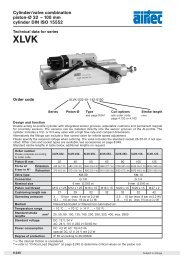
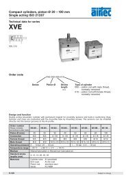
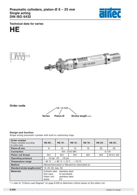
<strong>Pneumatic</strong> <strong>cylinders</strong>, <strong>piston</strong>-Ø 8 – <strong>25</strong> <strong>mm</strong><br />
<strong>Single</strong> <strong>acting</strong><br />
<strong>DIN</strong> <strong>ISO</strong> <strong>6432</strong><br />
Technical data for series<br />
HE<br />
Order code<br />
HE-16-0<strong>25</strong><br />
Series Piston-Ø Stroke length (<strong>mm</strong>)<br />
Design and function<br />
<strong>Single</strong> <strong>acting</strong> pneumatic cylinder with built-in cushioning rings.<br />
Order number<br />
Please complete according<br />
to order code.<br />
Piston-Ø <strong>mm</strong><br />
HE-08-…<br />
8<br />
HE-10-…<br />
10<br />
HE-12-…<br />
12<br />
HE-16-…<br />
16<br />
HE-20-…<br />
20<br />
HE-<strong>25</strong>-…<br />
<strong>25</strong><br />
Connection M5 (10/32 UNF) G 1/8<br />
Piston rod thread M4 M4 M6 M6 M8 M10x1.<strong>25</strong><br />
Operating pressure<br />
2 … 10 bar (29 … 145 psi)<br />
Temperature range<br />
– 30 °C … + 80 °C (– 22 °F … + 176 °F)<br />
Medium<br />
filtered/lubricated or filtered/non-lubricated air<br />
Standard stroke lengths (<strong>mm</strong>) 1) 10, <strong>25</strong>, 50, max. 50<br />
Materials Cylinder tube: stainless steel<br />
End caps: Al (anodized)<br />
Piston rod: stainless steel<br />
Seals: PU<br />
1)<br />
= refer to “Critical Load Diagram” on page 8.240 to determine critical values on the <strong>piston</strong> rod.<br />
8.060 Subject to change
<strong>Pneumatic</strong> <strong>cylinders</strong>, <strong>piston</strong>-Ø 8 – <strong>25</strong> <strong>mm</strong><br />
<strong>Single</strong> <strong>acting</strong><br />
<strong>DIN</strong> <strong>ISO</strong> <strong>6432</strong><br />
Technical data<br />
Force chart for series HE<br />
Piston-Ø<br />
stroke 10 stroke <strong>25</strong> stroke 50<br />
Min. Max. Min. Max. Min. Max.<br />
Ø 8 Extension 19.0 19.7 19.0 20.3 19.0 21.7<br />
Retraction 4.5 5.2 3.9 5.2 2.5 5.2<br />
Ø 10 Extension 36.0 36.7 36.0 37.3 36.0 38.7<br />
Retraction 4.5 5.2 3.9 5.2 2.5 5.2<br />
Ø 12 Extension 51.7 52.0 51.7 52.6 51.7 53.6<br />
Retraction 5.7 6.0 5.1 6.0 4.1 6.0<br />
Ø 16 Extension 87.5 90.0 87.5 93.5 87.5 99.7<br />
Retraction 15.0 17.5 11.5 17.5 5.3 17.5<br />
Ø 20 Extension 142.8 145.0 142.8 148.3 142.8 153.8<br />
Retraction 21.3 23.5 18.0 23.5 12.5 23.5<br />
Ø <strong>25</strong> Extension 243.7 245.0 243.7 247.0 243.7 <strong>25</strong>0.3<br />
Retraction 18.2 19.5 16.2 19.5 12.9 19.5<br />
Pressure 6 bar. The internal friction is considered.<br />
Dimensions for series<br />
HE<br />
M + stroke<br />
XC + stroke<br />
8<br />
SW<br />
P + stroke<br />
Ø A 1 AM B C CD CH EE EW KK L M N P SW WF XC<br />
8 4 12 M12 x 1,<strong>25</strong> 16 4 – M5 8 M4 6 86 12 46 19 16 64<br />
10 4 12 M12 x 1,<strong>25</strong> 16 4 – M5 8 M4 6 86 12 46 19 16 64<br />
12 6 16 M 16 x 1,5 19 6 5 M 5 12 M 6 9 104 18 48 22 22 75<br />
16 6 16 M 16 x 1,5 19 6 5 M 5 12 M 6 9 109 18 53 22 22 82<br />
20 8 20 M 22 x 1,5 27 8 7 G 1/8 16 M 8 12 131 20 67 27 24 95<br />
<strong>25</strong> 10 22 M 22 x 1,5 30 8 9 G 1/8 16 M10 x1,<strong>25</strong> 12 140 22 68 27 28 104<br />
H 9 d 13<br />
Subject to change<br />
8.061
<strong>Pneumatic</strong> <strong>cylinders</strong>, <strong>piston</strong>-Ø 16 – <strong>25</strong> <strong>mm</strong><br />
<strong>Single</strong> <strong>acting</strong><br />
Basis according to <strong>DIN</strong> <strong>ISO</strong> <strong>6432</strong><br />
Technical data for series<br />
HEZ, HES<br />
Order code<br />
HEZ-16-0<strong>25</strong>-100<br />
Series<br />
HEZ = air supply at back, central<br />
HES = air supply at back, lateral<br />
Piston-Ø<br />
Stroke<br />
length (<strong>mm</strong>)<br />
Type of cylinder<br />
Design and function<br />
<strong>Single</strong> <strong>acting</strong> pneumatic cylinder with built-in cushioning rings.<br />
Order number<br />
HEZ-16-… HEZ-20-… HEZ-<strong>25</strong>-…<br />
Please complete according<br />
to order code. HES-16-… HES-20-… HES-<strong>25</strong>-…<br />
Piston-Ø (<strong>mm</strong>) 16 20 <strong>25</strong><br />
Connection M 5 G 1/8 G 1/8<br />
Piston rod thread M6 M8 M10x1.<strong>25</strong><br />
Operating pressure<br />
2 … 10 bar (29 … 145 psi)<br />
Temperature range<br />
– 30 °C … + 80 °C (– 22 °F … + 176 °F)<br />
Medium<br />
filtered/lubricated or filtered/non-lubricated air<br />
Standard stroke lengths (<strong>mm</strong>) 1) 10, <strong>25</strong>, 50, max. 50<br />
Materials Cylinder tube: stainless steel<br />
End caps: Al (anodized)<br />
Piston rod: stainless steel<br />
Seals: PU<br />
1)<br />
= refer to “Critical Load Diagram” on page 8.240 to determine critical values on the <strong>piston</strong> rod.<br />
8.062 Subject to change
<strong>Pneumatic</strong> <strong>cylinders</strong>, <strong>piston</strong>-Ø 16 – <strong>25</strong> <strong>mm</strong><br />
<strong>Single</strong> <strong>acting</strong><br />
Basis according to <strong>DIN</strong> <strong>ISO</strong> <strong>6432</strong><br />
Technical data<br />
Force chart for series HEZ, HES<br />
Diameter<br />
stroke 10 stroke <strong>25</strong> stroke 50<br />
min. max. min. max. min. max.<br />
Ø 16 Extension 87.5 90.0 87.5 93.5 87.5 99.7<br />
Retraction 15.0 17.5 11.5 17.5 5.3 17.5<br />
Ø 20 Extension 142.8 145.0 142.8 148.3 142.8 153.8<br />
Retraction 21.3 23.5 18.0 23.5 12.5 23.5<br />
Ø <strong>25</strong> Extension 243.7 245.0 243.7 247.0 243.7 <strong>25</strong>0.3<br />
Retraction 18.2 19.5 16.2 19.5 12.9 19.5<br />
Pressure 6 bar. The internal friction is considered.<br />
Dimensions for series<br />
HEZ<br />
HES<br />
8<br />
Ø A A1 B C D3 E F G1 G2 K L L2 R M M1 CH<br />
16 M6 6 M 16 x 1.5 19 18 17.2 16 52 52.5 22 18 70 M5 90 90.5 5<br />
20 M8 8 M 22 x 1.5 27 <strong>25</strong>.5 22.2 20 65 67 24 20 83 G1/8 109 111 7<br />
<strong>25</strong> M10 x 1.<strong>25</strong> 10 M 22 x 1.5 30 28.5 27 22 66 68 28 22 88 G1/8 116 118 9<br />
Subject to change<br />
8.063
<strong>Pneumatic</strong> <strong>cylinders</strong>, <strong>piston</strong>-Ø 8 – 63 <strong>mm</strong><br />
<strong>DIN</strong> <strong>ISO</strong> <strong>6432</strong><br />
Accessories for series<br />
HE, HM<br />
Piston rod accessories<br />
Rod eye<br />
RO-<br />
Page 8.213<br />
Flexible coupling<br />
FK-<br />
Page 8.213<br />
Rod clevis with pin<br />
RD-<br />
Page 8.212<br />
Piston rod nut<br />
RL-<br />
Page 8.212<br />
Mounting accessories<br />
Foot mount<br />
l 8–<strong>25</strong><br />
RA-<br />
Page 8.086<br />
Foot mount<br />
l 32–63<br />
RA-<br />
Page 8.086<br />
Clevis mount<br />
l 8–63<br />
RC-<br />
Page 8.087<br />
Threaded bolts<br />
l 32–63<br />
RG-<br />
Page 8.087<br />
Clevis mount<br />
l 10– <strong>25</strong><br />
RH-<br />
Page 8.086<br />
Flange mount<br />
l 8–<strong>25</strong><br />
RB-<br />
Page 8.086<br />
Mounting nut<br />
l 8–<strong>25</strong><br />
RM-<br />
Mounting nut<br />
l 32–63<br />
RM-<br />
8.084 Subject to change
<strong>Pneumatic</strong> <strong>cylinders</strong>, <strong>piston</strong>-Ø 8 – 63 <strong>mm</strong><br />
<strong>DIN</strong> <strong>ISO</strong> <strong>6432</strong><br />
Accessories for series<br />
HM<br />
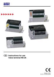
Proximity sensors<br />
Sensors<br />
ZS-<br />
Page 8.220<br />
Mounting bracket<br />
NT-<br />
Page 8.221<br />
Connecting cable<br />
KA-<br />
Page 8.221<br />
Linear guides<br />
8<br />
Linear guides<br />
LE-<br />
Page 8.200<br />
Mount-<br />
Mount-<br />
Piston- Foot Clevis Threaded Flange<br />
Rod Flexible Rod<br />
Piston<br />
Sensors ing<br />
ing<br />
Ø mount mount bolts mount<br />
clevis coupling eye<br />
rod nut<br />
bracket<br />
nut<br />
8 RA-10 RC-10 – RB-10<br />
RD-10 – – RM-10 RL-10<br />
ZS-5200 NT-0810<br />
10 RA-10 RC-10 – RB-10<br />
RD-10 – – RM-10 RL-10<br />
ZS-5201<br />
12 RA-16 RC-16 – RB-16<br />
RD-16 FK-16 RO-16 RM-16 RL-16<br />
ZS-5300 NT-1216<br />
16 RA-16 RC-16 – RB-16 RD-16 FK-16 RO-16 RM-16 RL-16<br />
ZS-5300-05<br />
20 RA-<strong>25</strong> RC-30 – RB-<strong>25</strong><br />
RD-20 FK-20 RO-20 RM-<strong>25</strong> RL-20<br />
ZS-5301 NT-20<strong>25</strong><br />
<strong>25</strong> RA-<strong>25</strong> RC-30 – RB-<strong>25</strong><br />
RD-<strong>25</strong> FK-32 RO-<strong>25</strong> RM-<strong>25</strong> RL-<strong>25</strong><br />
ZS-6300<br />
32 RA-32 RC-32 RG-32 –<br />
NT-0032 RD-32 FK-33 RO-32 RM-32 RL-32<br />
ZS-6301<br />
40 RA-40 RC-40 RG-40 –<br />
NT-0040 RD-40 FK-41 RO-40 RM-40 RL-40<br />
ZS-7300<br />
50 RA-50 RC-50 RG-50 –<br />
NT-0050 RD-63 – RO-50 RM-63 RL-63<br />
ZS-7301<br />
63 RA-63 RC-63 RG-63 – NT-0063 RD-63 – RO-50 RM-63 RL-63<br />
For <strong>piston</strong>-Ø 8, 10 and 12 <strong>mm</strong> only electronic switches (ZS-6300, ZS-6301, ZS-7000 or ZS-7001) can be used.<br />
Subject to change<br />
8.085
Accessories for<br />
pneumatic <strong>cylinders</strong>, <strong>piston</strong>-Ø 8 – 63 <strong>mm</strong><br />
Mounting accessories for series<br />
HE, HM<br />
Foot mount<br />
Material: steel (zinc-plated)<br />
Order number A B C D E F G H I J K L M R<br />
RA-10 35 16 26 11 4.5 <strong>25</strong> 16 12 – – – – 3 10<br />
RA-16 42 20 32.5 14 5.5 32 20 16 – – – – 4 12.5<br />
RA-<strong>25</strong> 54 <strong>25</strong> 45 17 6.6 40 <strong>25</strong> 22 – – – – 5 20<br />
RA-32 66 21 49 14 7 52 28 30 52 14 28 7 4 –<br />
RA-40 80 30 58 20 9 60 33 38 60 18 30 9 5 –<br />
RA-50 90 30 70 20 9 70 40 45 70 20 40 9 6 –<br />
RA-63 96 30 80 20 9 76 45 45 76 20 50 9 6 –<br />
Flange mount<br />
Clevis mount<br />
Material: steel (zinc-plated)<br />
Order number A B C R R 1 S<br />
RB-10 12 4.5 30 11 5 3<br />
RB-16 16 5.5 40 15 6 4<br />
RB-<strong>25</strong> 22 6.6 50 20 8 5<br />
Material: steel (zinc-plated)<br />
Order-No. A B C D E F G H I<br />
RH-10 24 26 6 38 9 4 6 20 12<br />
RH-16 36 38 10 58 13 6 8 <strong>25</strong> 16<br />
RH-<strong>25</strong> 44 46 10 66 13 6 8 30 22<br />
0<br />
+1.5<br />
e9<br />
– 0.2 + 0.5<br />
8.086 Subject to change
Accessories for<br />
pneumatic <strong>cylinders</strong>, <strong>piston</strong>-Ø 8 – 63 <strong>mm</strong><br />
Mounting accessories for series<br />
HE, HM<br />
Clevis mount<br />
for Ø 8 – <strong>25</strong><br />
Material: steel (zinc-plated)<br />
Order number for Cyl.-Ø B B 1 C H L N O R S E<br />
RC-10 8 + 10 4.5 4 12.5 24 20 8.1 17 5 2.5 5<br />
RC-16 12 + 16 5.5 6 15 27 <strong>25</strong> 12.1 23 7 3 5<br />
RC-30 20 + <strong>25</strong> 6.6 8 20 30 32 16.1 30 10 4 6<br />
for Ø 32 – 63<br />
Material: steel (zinc-plated)<br />
Order number D 1 D 2 E E 1 G M 1 N 1 N 2 R 1 S U 1 U 2 U 3 V Z 1 Z 2 SW 2<br />
RC-32 10 15 7 35 20 M 8 x 1 24 40 12 4 20 50.1 38.1 4 6 18 13<br />
RC-40 12 20 9 40 27 M10 x 1 30 50 13 5 28 60.1 46.1 5 7 21.6 17<br />
RC-50 14 23 9 45 30 M12 x 1.5 34 54 14 6 36 74.1 57.1 6 9 26.4 19<br />
RC-63 16 23 9 50 34 M14 x 1.5 35 65 16 6 42 88.1 70.1 6 16 35 19<br />
8<br />
Threaded bolts<br />
Material: steel (zinc-plated)<br />
Order number D 1 H L L 1 SW 1<br />
RG-32 10 51 1<strong>25</strong> 47 5<br />
RG-40 12 61 146 57 6<br />
RG-50 14 75 158 62 6<br />
RG-63 16 90 162 64 8<br />
Subject to change<br />
8.087
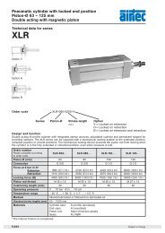
Piston rod accessories<br />
Assignment to series<br />
Series Cylinder Ø Piston rod<br />
Piston rod Flexible<br />
Rod clevis<br />
<strong>mm</strong> thread nut coupling<br />
Rod eye<br />
HM Ø 8 and 10 M 4 RD-10 RL-10 – –<br />
NXD Ø 12<br />
HM Ø 12 and 16<br />
M 6 RD-16 RL-16 FK-16 RO-16<br />
NXD Ø 16<br />
HM Ø 20 M 8 RD-20 RL-20 FK-20 RO-20<br />
XV Ø 20 and <strong>25</strong><br />
NXD Ø 20 to 40<br />
HM Ø <strong>25</strong> M 10 x 1,<strong>25</strong> RD-<strong>25</strong> RL-<strong>25</strong> FK-32 RO-<strong>25</strong><br />
XL Ø 32<br />
XV Ø 32 and 40<br />
HM Ø 32 M 10 RD-32 RL-32 FK-33 RO-32<br />
HM Ø 40 M 12 RD-40 RL-40 FK-41 RO-40<br />
HM Ø 50 and 63 M 16 RD-63 RL-63 – RO-50<br />
NXD Ø 50 and 63<br />
XL Ø 40<br />
M 12 x 1,<strong>25</strong> FD-40 FE-40 FK-40 FO-40<br />
XV Ø 50 and 63<br />
NXD Ø 80<br />
XL Ø 50 and 63<br />
M 16 x 1,5 FD-63 FE-63 FK-63 FO-63<br />
NXD Ø 100<br />
XL Ø 80 and 100<br />
M 20 x 1,5 FD-80 FE-80 FK-80 FO-80<br />
XV Ø 80 and 100<br />
XL Ø 1<strong>25</strong> M 27 x 2 FD-1<strong>25</strong> FE-1<strong>25</strong> FK-1<strong>25</strong> FO-1<strong>25</strong><br />
XG Ø 160 and 200 M 36 x 2 FD-200 FE-200 – FO-200<br />
Rod clevis with pin<br />
Order number A B C D E F G H<br />
RD-10 M4 8 16 11,5 4 21 8 4<br />
RD-16 M 6 12 24 16 6 31 12 6<br />
RD-20 M 8 16 32 22 8 42 16 8<br />
RD-<strong>25</strong> M 10 x 1,<strong>25</strong> 20 40 26 10 52 20 10<br />
RD-32 M10 20 40 26 10 52 20 10<br />
RD-40 M12 24 48 32 12 62 24 12<br />
RD-63 M16 32 64 36 16 83 32 16<br />
FD-40 M 12 x 1,<strong>25</strong> 24 48 32 12 62 24 12<br />
FD-63 M 16 x 1,5 32 64 40 16 83 32 16<br />
FD-80 M 20 x 1,5 40 80 50 20 105 40 20<br />
FD-1<strong>25</strong> M 27 x 2 54 110 65 30 148 55 30<br />
FD-200 M36 x 2 72 144 84 35 188 70 35<br />
Material: steel (zinc-plated)<br />
spring steel<br />
Piston rod nut<br />
Order number A B C<br />
RL-10 M4 3,2 7<br />
RL-16 M6 5 10<br />
RL-20 M8 6,5 13<br />
RL-<strong>25</strong> M 10 x 1,<strong>25</strong> 6 17<br />
RL-32 M10 6 17<br />
RL-40 M12 7 19<br />
RL-63 M16 8 24<br />
FE-40 M 12 x 1,<strong>25</strong> 7 19<br />
FE-63 M 16 x 1,5 8 24<br />
FE-80 M 20 x 1,5 9 30<br />
FE-1<strong>25</strong> M 27 x 2 12 41<br />
FE-200 M36 x 2 14 55<br />
Rod clevis FD-1<strong>25</strong> and FD-200, pin with snap rings.<br />
Material: steel (zinc-plated)<br />
8.212 Subject to change
Piston rod accessories<br />
Flexible coupling<br />
view A<br />
Material: steel (zinc-plated)<br />
Order<br />
number<br />
A B C D E F G K L M N O P<br />
FK-16 M 6 SW 10 SW 5 6 17.5 SW 7 8.5 35 10 3.5 10 13 15<br />
FK-20 M 8 SW 13 SW 7 8 28.5 SW 11 12.5 57 20 4 20 17 19<br />
FK-32 M 10 x 1.<strong>25</strong> SW 17 SW 12 14 35 SW 19 22 71 20 5 20 30 32<br />
FK-33 M10 SW17 SW12 14 35 SW19 22 71 20 5 20 30 32<br />
FK-40 M 12 x 1.<strong>25</strong> SW 19 SW 12 14 35 SW 19 22 75 24 5 20 30 32<br />
FK-41 M12 SW19 SW12 14 35 SW19 22 75 24 5 20 30 32<br />
FK-63 M 16 x 1.5 SW 24 SW 20 22 54 SW 30 32 103 32 8 32 41 45<br />
FK-80 M 20 x 1.5 SW 30 SW 20 22 54 SW 30 32 119 40 8 40 41 45<br />
FK-1<strong>25</strong> M 27 x 2 SW 46 SW 24 32.2 60 SW 54 57 147 49.5 9.5 40 65 70<br />
Rod eye<br />
8<br />
Material: steel (zinc-plated)<br />
stainless steel<br />
Order<br />
number<br />
d 3 d d 1 d 2 d 4 d 5 B C 1 W L 3 L 4 h 1 “<br />
RO-16 M 6 6 8.9 20 10 13 9 6.75 11 12 40 30 13<br />
RO-20 M 8 8 10.4 24 12.5 16 12 9 13 16 48 36 13<br />
RO-<strong>25</strong> M 10 x 1.<strong>25</strong> 10 12.9 28 15 19 14 10.5 17 20 57 43 13<br />
RO-32 M10 10 12.9 28 15 19 14 10.5 17 20 57 43 13<br />
RO-40 M12 12 15.4 32 17.5 22 16 12 19 22 66 50 13<br />
RO-50 M16 16 19.3 42 22 27 21 15 22 28 85 64 15<br />
FO-40 M 12 x 1.<strong>25</strong> 12 15.4 32 17.5 22 16 12 19 22 66 50 13<br />
FO-63 M16x1.5 16 19.3 42 22 27 21 15 22 28 85 64 15<br />
FO-80 M 20 x 1.5 20 24.3 50 27.5 34 <strong>25</strong> 18 32 33 102 77 15<br />
FO-1<strong>25</strong> M27x2 30 34.8 70 40 51 37 <strong>25</strong> 41 51 145 110 15<br />
FO-200 M36x2 35 37.7 80 46 56 43 28 50 56 165 1<strong>25</strong> 15<br />
Subject to change<br />
8.213
Proximity sensors<br />
Wiring diagram<br />
Dimensions<br />
ZS-5200<br />
ZS-5201<br />
ZS-5200, ZS-5300,<br />
ZS-5300-05,<br />
ZS-6300, ZS-7300<br />
ZS-5300, ZS-5300-05<br />
ZS-5301<br />
ZS-6300, ZS-7300<br />
ZS-6301, ZS-7301<br />
ZS-5201, ZS-5301,<br />
ZS-6301, ZS-7301<br />
4<br />
1<br />
3<br />
Function principles<br />
Magnetic field sensors are actuated by magnetic fields and are especially suited for <strong>piston</strong> position detection in<br />
pneumatic <strong>cylinders</strong>. Based on the fact that magnetic fields can permeate non-magnetizable metals, it is possible<br />
to detect a permanent magnet attached to the <strong>piston</strong> through the aluminum wall of the cylinder.<br />
Mounting tip<br />
The sensor is firmly fixed in the groove by clockwise rotation of the screw.<br />
Order number ZS-5200 ZS-5201 ZS-5300 ZS-5300-05 ZS-5301<br />
Design 2-pole Reed sensor 3-pole Reed sensor*<br />
(non-polarized) normally open<br />
normally open<br />
Cable l 3, Lif9Y-11Y, PUR l 3, LifYY-11Y, PUR<br />
Cable cross section 2 x 0.14 <strong>mm</strong> 2 3 x 0.14 <strong>mm</strong> 2<br />
Cable length 3 m 0,3 m 3 m 5 m 0,3 m<br />
Cable plug – M8 – – M8<br />
Overtravel speed<br />
≤ 10 m/s<br />
Max. absolute hysteresis<br />
≤ 1 <strong>mm</strong><br />
Temperature drift<br />
≤ 0.1 <strong>mm</strong><br />
Min. absolute repeat accuracy<br />
≤ ± 0.1 <strong>mm</strong><br />
Operating temperature – <strong>25</strong> °C … + 70 °C<br />
Degree of protection IP 67<br />
Housing material Plastic PA 12<br />
Switching status indication<br />
LED yellow<br />
Rated operational voltage 3 … 140 VAC / 4 … 200 VDC 10 … 30 V DC*<br />
Rated operational DC ≤ 100 mA ≤ 500 mA<br />
current I E AC ≤ 100 mA ≤ 500 mA<br />
Breaking capacity<br />
10 W<br />
No-load current<br />
0 mA<br />
Max. OFF-state current<br />
0 mA<br />
Max. switching frequency<br />
≤ 0.5 kHz<br />
Rated insulation voltage<br />
≤ 0.5 kV<br />
Short-circuit protection<br />
no<br />
Max. voltage drop at I E ≤ 3 V ≤ 0.5 V<br />
Wire breakage<br />
no<br />
Reverse polarity protection<br />
yes<br />
Vibration resistance<br />
55 Hz (1 <strong>mm</strong>)<br />
Shock resistance<br />
30 g (11 ms)<br />
Explosion proof –<br />
* Useable as 2-wire contact, voltage 0 … 30 V AC / 0 … 30 V DC, LED has no function.<br />
8.220 Subject to change
Proximity sensors<br />
Mounting bracket for round cylinder Ø 8 – 63 <strong>mm</strong><br />
Material: PA,<br />
steel zinc plated<br />
Order number<br />
NT-0810<br />
NT-1216<br />
NT-20<strong>25</strong><br />
NT-0032<br />
NT-0040<br />
NT-0050<br />
NT-0063<br />
Piston-Ø<br />
8 and 10 <strong>mm</strong><br />
12 and 16 <strong>mm</strong><br />
(Series XG Ø 160 and 200 <strong>mm</strong>)<br />
20 and <strong>25</strong> <strong>mm</strong><br />
(Series XG Ø <strong>25</strong>0 and 320 <strong>mm</strong>)<br />
32 <strong>mm</strong><br />
40 <strong>mm</strong><br />
50 <strong>mm</strong><br />
63 <strong>mm</strong><br />
Material: metal,<br />
plastic PA GI/6T<br />
Order number<br />
NT-08<strong>25</strong><br />
NT-3263<br />
Piston-Ø<br />
8 – <strong>25</strong> <strong>mm</strong><br />
32 – 63 <strong>mm</strong><br />
Connecting cable for ZS-5201, ZS-5301, ZS-6301 and ZS-7301<br />
BU 3<br />
4 BK<br />
1 BN<br />
Cable: PUR, black, 3 x 0,<strong>25</strong> <strong>mm</strong> 2 , l 3.9, high flexible<br />
Operating voltage 0 … 48 V AC/DC<br />
Order number Length of cable Connection<br />
KA-30 3 m 8 <strong>mm</strong> sensor snap-in, straight<br />
KA-50 5 m 8 <strong>mm</strong> sensor snap-in, straight<br />
KA-51 5 m 8 <strong>mm</strong> sensor snap-in, 90°<br />
KA-100 10 m 8 <strong>mm</strong> sensor snap-in, straight<br />
KA-101 10 m 8 <strong>mm</strong> sensor snap-in, 90°<br />
Proximity sensors electronic<br />
Order number ZS-6300 ZS-6301 ZS-7300 ZS-7301<br />
Design<br />
electronic, magnet-induktive sensor,<br />
normally open PNP output<br />
Cable<br />
l 3, LifYY-11Y, PUR<br />
Cable cross section 3 x 0.14 <strong>mm</strong> 2<br />
Cable lengths 3 m 0.3 m 3 m 0.3 m<br />
Cable plug – M8 – M8<br />
Overtravel speed<br />
≤ 10 m/s<br />
Max. absolute hysteresis<br />
≤ 1 <strong>mm</strong><br />
Temperature drift<br />
≤ 0.1 <strong>mm</strong><br />
Min. absolute repeat accuracy<br />
≤ ± 0.1 <strong>mm</strong><br />
Operating temperature – <strong>25</strong> °C … + 70 °C<br />
Degree of protection IP 67<br />
Housing material Plastic, PA 12<br />
Switching status indication<br />
LED yellow<br />
Rated operational voltage<br />
10 … 30 V DC, max. ripple ≤ 10 % Upp<br />
Rated operational DC ≤ 200 mA<br />
current I E AC –<br />
Breaking capacity<br />
6 W<br />
No-load current<br />
≤ 15 mA<br />
Max. OFF-state current<br />
≤ 0.1 mA<br />
Max. switching frequency<br />
≤ 1 kHz<br />
Rated insulation voltage<br />
≤ 0.5 kV<br />
Short-circuit protection<br />
yes, cyclic<br />
Max. voltage drop at I E<br />
≤ 1.8 V<br />
Wire breakage<br />
yes<br />
Reverse polarity protection<br />
yes /complete<br />
Vibration resistance<br />
55 Hz (1 <strong>mm</strong>)<br />
Shock resistance<br />
30 g (11 ms)<br />
Explosion proof – II 3 GD EEx nA II T4 X IP 67 T 110 °C<br />
8<br />
Subject to change<br />
8.221
Technical charts<br />
This table shows the air consumption for a single stroke of 100 <strong>mm</strong>. These statements are based upon extension<br />
and are in Nl.<br />
Piston-Ø<br />
Air pressure in bar/ psi<br />
<strong>mm</strong> 2 (29 psi) 3 (43.4 psi) 4 (58 psi) 5 (72.5 psi) 6 (87 psi) 7 (101.5 psi) 8 (116 psi)<br />
8 0.02 0.02 0.03 0.03 0.04 0.04 0.05<br />
10 0.02 0.03 0.04 0.05 0.05 0.06 0.07<br />
12 0.03 0.05 0.06 0.07 0.08 0.09 0.10<br />
16 0.06 0.08 0.10 0.12 0.14 0.16 0.18<br />
20 0.09 0.13 0.16 0.19 0.22 0.<strong>25</strong> 0.28<br />
<strong>25</strong> 0.15 0.20 0.<strong>25</strong> 0.29 0.34 0.39 0.44<br />
32 0.24 0.32 0.40 0.48 0.56 0.64 0.72<br />
40 0.38 0.50 0.63 0.75 0.88 1.01 1.13<br />
50 0.59 0.79 0.98 1.18 1.37 1.57 1.77<br />
63 0.94 1.<strong>25</strong> 1.56 1.87 2.18 2.49 2.81<br />
80 1.51 2.01 2.51 3.02 3.52 4.02 4.52<br />
100 2.36 3.14 3.93 4.71 5.50 6.28 7.07<br />
Critical Load Diagram for the <strong>piston</strong> rod<br />
Piston rod-Ø<br />
Stroke of cylinder<br />
Critical load for the <strong>piston</strong> rod Fk (N) is calculated with a safety factor of 5-times.<br />
Elastic cases of buckling<br />
according to „Euler“<br />
F k = permitted critical force (N)<br />
E = elasticity module (N/<strong>mm</strong> 2 )<br />
l = moment of inertia (<strong>mm</strong> 4 )<br />
L k = effective length of critical load<br />
S = security<br />
First elastic<br />
case of buckling<br />
open end at B<br />
fixed restraint at A<br />
Lk = 2 x L<br />
Second elastic<br />
case of buckling<br />
joint at B<br />
joint at A<br />
Lk = L<br />
8.240 Subject to change