Green Wireless Communications: A Time-Reversal Paradigm
Green Wireless Communications: A Time-Reversal Paradigm
Green Wireless Communications: A Time-Reversal Paradigm

You also want an ePaper? Increase the reach of your titles
YUMPU automatically turns print PDFs into web optimized ePapers that Google loves.
1698 IEEE JOURNAL ON SELECTED AREAS IN COMMUNICATIONS, VOL. 29, NO. 8, SEPTEMBER 2011<br />
<strong>Green</strong> <strong>Wireless</strong> <strong>Communications</strong>:<br />
A <strong>Time</strong>-<strong>Reversal</strong> <strong>Paradigm</strong><br />
Beibei Wang, Member, IEEE, Yongle Wu, Feng Han, Student Member, IEEE, Yu-Han Yang, Student<br />
Member, IEEE, and K. J. Ray Liu, Fellow, IEEE<br />
Abstract—<strong>Green</strong> wireless communications have received considerable<br />
attention recently in hope of finding novel solutions<br />
to improve energy efficiency for the ubiquity of wireless applications.<br />
In this paper, we argue and show that the timereversal<br />
(TR) signal transmission is an ideal paradigm for green<br />
wireless communications because of its inherent nature to fully<br />
harvest energy from the surrounding environment by exploiting<br />
the multi-path propagation to re-collect all the signal energy that<br />
would have otherwise been lost in most existing communication<br />
paradigms. A green wireless technology must ensure low energy<br />
consumption and low radio pollution to others than the intended<br />
user. In this paper, we show through theoretical analysis, numerical<br />
simulations and experiment measurements that the TR<br />
wireless communications, compared to the conventional direct<br />
transmission using a Rake receiver, reveals significant transmission<br />
power reduction, achieves high interference alleviation ratio,<br />
and exhibits large multi-path diversity gain. As such it is an ideal<br />
paradigm for the development of green wireless systems. The<br />
theoretical analysis and numerical simulations show an order of<br />
magnitude improvement in terms of transmit power reduction<br />
and interference alleviation. Experimental measurements in a<br />
typical indoor environment also demonstrate that the transmit<br />
power with TR based transmission can be as low as 20% of<br />
that without TR, and the average radio interference (thus radio<br />
pollution) even in a nearby area can be up to 6 dB lower. A<br />
strong time correlation is found to be maintained in the multipath<br />
channel even when the environment is varying, which<br />
indicates high bandwidth efficiency can be achieved in TR radio<br />
communications.<br />
Index Terms—<strong>Green</strong> wireless communications, time reversal,<br />
energy efficiency, low radio pollution.<br />
I. INTRODUCTION<br />
IN RECENT years, with the explosive growth of wireless<br />
communication industry in terms of network infrastructures,<br />
network users, and various new applications, the energy<br />
consumption of wireless networks and devices is experiencing<br />
a dramatic increase. Because of ubiquity of wireless applications,<br />
such an increasing energy consumption not only<br />
results in a high operational cost and an urgent demand for<br />
battery/energy capacity to wireless communications operators,<br />
but also causes a more severe electromagnetic (EM) pollution<br />
to the global environment. Therefore, an emerging concept of<br />
“<strong>Green</strong> <strong>Communications</strong>” has received considerable attention<br />
in hope of finding novel solutions to improve energy efficiency,<br />
relieve/reduce radio pollution to unintended users, and maintain/improve<br />
performance metrics.<br />
Manuscript received 8 October 2010; revised 14 February 2011.<br />
B. Wang and Y. Wu are with Qualcomm Inc., San Diego, CA 92121, USA<br />
(e-mail: {beibeiw, yonglew}@qualcomm.com).<br />
F. Han, Y.-H. Yang, and K. J. R. Liu are with the Department of Electrical<br />
and Computer Engineering, University of Maryland, College Park, MD 20742,<br />
USA (e-mail: {hanf, yhyang, kjrliu}@umd.edu).<br />
Digital Object Identifier 10.1109/JSAC.2011.110918.<br />
0733-8716/11/$25.00 c○ 2011 IEEE<br />
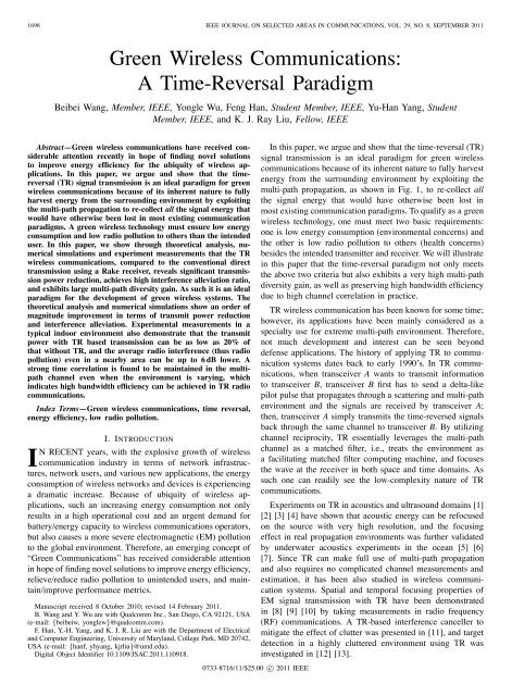
In this paper, we argue and show that the time-reversal (TR)<br />
signal transmission is an ideal paradigm for green wireless<br />
communications because of its inherent nature to fully harvest<br />
energy from the surrounding environment by exploiting the<br />
multi-path propagation, as shown in Fig. 1, to re-collect all<br />
the signal energy that would have otherwise been lost in<br />
most existing communication paradigms. To qualify as a green<br />
wireless technology, one must meet two basic requirements:<br />
one is low energy consumption (environmental concerns) and<br />
the other is low radio pollution to others (health concerns)<br />
besides the intended transmitter and receiver. We will illustrate<br />
in this paper that the time-reversal paradigm not only meets<br />
the above two criteria but also exhibits a very high multi-path<br />
diversity gain, as well as preserving high bandwidth efficiency<br />
due to high channel correlation in practice.<br />
TR wireless communication has been known for some time;<br />
however, its applications have been mainly considered as a<br />
specialty use for extreme multi-path environment. Therefore,<br />
not much development and interest can be seen beyond<br />
defense applications. The history of applying TR to communication<br />
systems dates back to early 1990’s. In TR communications,<br />
when transceiver A wants to transmit information<br />
to transceiver B, transceiver B first has to send a delta-like<br />
pilot pulse that propagates through a scattering and multi-path<br />
environment and the signals are received by transceiver A;<br />
then, transceiver A simply transmits the time-reversed signals<br />
back through the same channel to transceiver B. By utilizing<br />
channel reciprocity, TR essentially leverages the multi-path<br />
channel as a matched filter, i.e., treats the environment as<br />
a facilitating matched filter computing machine, and focuses<br />
the wave at the receiver in both space and time domains. As<br />
such one can readily see the low-complexity nature of TR<br />
communications.<br />
Experiments on TR in acoustics and ultrasound domains [1]<br />
[2] [3] [4] have shown that acoustic energy can be refocused<br />
on the source with very high resolution, and the focusing<br />
effect in real propagation environments was further validated<br />
by underwater acoustics experiments in the ocean [5] [6]<br />
[7]. Since TR can make full use of multi-path propagation<br />
and also requires no complicated channel measurements and<br />
estimation, it has been also studied in wireless communication<br />
systems. Spatial and temporal focusing properties of<br />
EM signal transmission with TR have been demonstrated<br />
in [8] [9] [10] by taking measurements in radio frequency<br />
(RF) communications. A TR-based interference canceller to<br />
mitigate the effect of clutter was presented in [11], and target<br />
detection in a highly cluttered environment using TR was<br />
investigated in [12] [13].
WANG et al.: GREEN WIRELESS COMMUNICATIONS: A TIME-REVERSAL PARADIGM 1699<br />
from practical indoor multi-path channels are shown in Section<br />
V. We briefly present a few prospective applications of the TRbased<br />
technology based on its focusing effect in Section VI,<br />
which suggest that TR-based communication is a promising<br />
direction in addition to power efficiency and low interference<br />
pollution. Finally, conclusions are drawn in Section VII.<br />
Fig. 1.<br />
Illustration of a typical urban multi-path environment.<br />
Leveraging from the spatial and temporal focusing effect,<br />
in this paper, we show that the TR technique is indeed an<br />
ideal green wireless communication paradigm which can efficiently<br />
harvest energy from the environment. We first derive<br />
the theoretical transmission power reduction and interference<br />
alleviation of the TR-based transmission compared to direct<br />
transmission with a Rake receiver. Our theoretical analysis<br />
and simulations show that a potential of over an order of<br />
magnitude of power reduction and interference alleviation can<br />
be achieved. We also investigate the multi-path diversity gain<br />
of the TR-based transmission, in which we demonstrate a very<br />
high multi-path diversity gain exhibiting in a TR system. In<br />
essence, TR transmission treats each multi-path as a virtual<br />
antenna and makes full use of all the multi-paths.<br />
Experimental results obtained from measurements in real<br />
RF multi-path environment are shown to demonstrate the<br />
great potential of TR-based transmission as an energy-efficient<br />
green wireless communication paradigm. It is found that in a<br />
typical indoor multi-path environment, in order to achieve the<br />
same receiver performance, TR-based transmission only costs<br />
as low as 20 % of the transmission power needed in direct<br />
transmission; moreover, the average interference can be up to<br />
6 dB lower than that caused by direct transmission when the<br />
interfered receiver is only 1 m away from the intended receiver.<br />
It is also shown from channel measurements in different time<br />
epochs that, a static indoor multi-path environment is strongly<br />
time-correlated; therefore, there is no need for the receiver to<br />
keep sending pilot pulses to the transmitter, and the spectral<br />
efficiency can be much higher than typically achieved value<br />
of 50 %. We also performed extensive numerical simulation<br />
to validate the theoretical derivation.<br />
The rest of this paper is organized as follows. In Section II,<br />
we introduce the system model and multi-path channel model.<br />
In Section III, we investigate the performance of the TRbased<br />
transmission in terms of power reduction, interference<br />
alleviation, and multi-path diversity gain. Simulation studies<br />
are presented in Section IV, and experimental results obtained<br />
II. SYSTEM MODEL<br />
In this paper, we consider a slow fading wireless channel<br />
with a large delay spread. The channel impulse response (CIR)<br />
at time k between the transmitter and the receiver in discrete<br />
time domain is modeled as<br />
L−1<br />
∑<br />
h[k] = h l δ[k − l], (1)<br />
l=0<br />
where h l is the complex amplitude of l-th tap of the CIR, and<br />
L is the number of channel taps. Since we assume that the<br />
channel is slow fading, the channel taps will not vary during<br />
the observation time. To gain some insight into the TR system<br />
while keeping the model analytically tractable, the CIRs<br />
associated with different receivers at different locations are<br />
assumed to be independent, e.g., when the receivers are very<br />
far apart. Furthermore, we assume independence among the<br />
taps of each CIR, i.e., the paths of each CIR are uncorrelated.<br />
Each h[l] is a circular symmetric complex Gaussian (CSCG)<br />
random variable with zero mean and<br />
E[|h[l]| 2 ]=e − lT S<br />
σ T , (2)<br />
where T S is the sampling period of this system such that 1/T S<br />
equals the system bandwidth B, andσ T is the delay spread<br />
[14] of the channel.<br />
A TR-based communication system is very simple. For<br />
example, a base station tries to transmit some information to<br />
an end user. Prior to the transmission, the end user has to send<br />
out a delta-like pilot pulse which propagates to the base station<br />
through a multi-path channel, where the base station keeps a<br />
record of the received waveform. Then, the base station time<br />
reverses the received waveform, and use the normalized timereversed<br />
conjugate signals as a basic waveform, i.e.,<br />
/ √ √√<br />
L−1<br />
∑<br />
g[k] = h ∗ [L − 1 − k] |h[l]| 2 ,k=0, 1,...,L− 1.<br />
l=0<br />
(3)<br />
In the above equation, we ignore the noise term to simplify<br />
derivation 1 . Thanks to the channel reciprocity, the multi-path<br />
channel forms a natural matched filter to the basic waveform<br />
g[k],k =0, 1,...,L− 1, and hence a peak is expected at the<br />
receiver.<br />
The base station loads the data stream on the basic waveform,<br />
and transmits the signal into the wireless channel.<br />
Usually the baud rate is much lower than the sampling rate,<br />
and the ratio of the sampling rate to the baud rate is also<br />
known as the rate back-off factor D [10]. Mathematically, if a<br />
sequence of information symbols are denoted by {X[k]} and<br />
assumed to be i.i.d. complex random variables with zero mean<br />
1 By sending a large number of channel training sequences from the receiver,<br />
the noise term is diminishing asymptotically.
1700 IEEE JOURNAL ON SELECTED AREAS IN COMMUNICATIONS, VOL. 29, NO. 8, SEPTEMBER 2011<br />
Fig. 2.<br />
The block diagram of a TR-based communication system.<br />
and a variance of P , the transmitted signal into the wireless<br />
channels can be expressed as<br />
( )<br />
S[k] = X [D] ∗ g [k], (4)<br />
where X [D] [k] is an up-sampled sequence of X[k],<br />
{<br />
X [D] X[k/D], if k mod D = 0,<br />
[k] =<br />
(5)<br />
0, if k mod D ≠ 0.<br />
The signal received at the receiver is the convolution<br />
of {S[k]} and {h[k]}, plus additive white Gaussian noise<br />
(AWGN) {ñ i [k]} with zero-mean and variance σ 2 . The receiver<br />
simply performs a one-tap gain adjustment to the<br />
received signal, i.e., multiplying a coefficient a, and then<br />
down-samples it with the same factor D. The signal before<br />
down-sampling can be represented as<br />
(<br />
)<br />
Y [D] [k] =a X [D] ∗ g ∗ h [k]+añ[k]. (6)<br />
Accordingly, the down-sampled signal Y [k] is as follows (for<br />
simplicity, L − 1 is assumed to be a multiple of D)<br />
(2L−2)/D<br />
∑<br />
Y [k] =a (h ∗ g)[Dl]X[k − l]+an[k], (7)<br />
where<br />
l=0<br />
(h ∗ g)[k] =<br />
L−1 ∑<br />
l=0<br />
h[l]h ∗ [L − 1 − k + l]<br />
√<br />
L−1<br />
, (8)<br />
∑<br />
|h[l]| 2<br />
with k = 0, 1, ··· , 2L − 2, and n[k] = ñ[Dk], a white<br />
Gaussian additive noise with zero mean and variance σ 2 .<br />
The block diagram of a TR-based communication system is<br />
summarized in Fig. 2, and we can see that both the transmitter<br />
and receiver are of very low complexity.<br />
III. PERFORMANCE ANALYSIS<br />
In this part, we compare the performance of the TR system<br />
to that of conventional direct transmission with Rake<br />
receivers, and evaluate several performance metrics, including<br />
the transmit power in order to achieve the same signalto-interference-and-noise<br />
ratio (SINR), and the interference<br />
caused to unintended receivers. Finally, we analyze the multipath<br />
gain of the TR system.<br />
A. Power Reduction<br />
Note that in (8), when k = L − 1, it corresponds to the<br />
maximum-power central peak of the autocorrelation function<br />
of the CIR, i.e.<br />
(h ∗ g)[L − 1] = √ L−1 ∑<br />
|h[l]| 2 . (9)<br />
l=0<br />
l=0<br />
Subject to the one-tap constraint, the receiver is designed<br />
to estimate X[k − L−1<br />
D<br />
] solely based on the observation of<br />
Y [k]. Then, the remaining components of Y [k] can be further<br />
categorized into inter-symbol interference (ISI) and noise, as<br />
shown in the following<br />
Y [k]= a(h ∗ g)[L − 1]X[k − L − 1<br />
D ] (Signal)<br />
+ a<br />
(2L−2)/D<br />
∑<br />
l=0<br />
l≠(L−1)/D<br />
(h ∗ g)[Dl]X[k − l] (ISI)<br />
+ an[k] (Noise) (10)<br />
Given a specific realization of the random CIRs, from eqn.<br />
(10), one can calculate the signal power P Sig as 2<br />
[ ∣∣∣∣<br />
P Sig = E X (h ∗ g)[L − 1]X[k − L − 1 ∣ ]<br />
∣∣∣<br />
2<br />
D ]<br />
= P |(h ∗ g)[L − 1]| 2 = P<br />
( L−1<br />
) ∑<br />
|h[l]| 2 , (11)<br />
l=0<br />
where E X [·] represents the expectation over X. Similarly, the<br />
ISI can be derived as<br />
⎡<br />
2⎤<br />
(2L−2)/D<br />
∑<br />
P ISI = E X<br />
⎢<br />
⎣<br />
(h ∗ g)[Dl]X[k − l]<br />
⎥<br />
⎦<br />
l=0<br />
∣<br />
∣<br />
= P<br />
l≠(L−1)/D<br />
(2L−2)/D<br />
∑<br />
l=0<br />
l≠(L−1)/D<br />
|(h ∗ g)[Dl]| 2 , (12)<br />
As D increases, the ISI term P ISI will gradually decrease.<br />
In the regime where D is such a large positive number that<br />
P ISI → 0, we can focus on the signal-to-noise ratio (SNR)<br />
only:<br />
SNR = P Sig<br />
σ 2 . (13)<br />
Without using the TR-based transmission, we can express<br />
the received signal of direct transmission as<br />
L−1<br />
∑<br />
Y DT [k] =(X ∗ h)[k]+n[k] = h[l]X[k − l]+n[k], (14)<br />
where the superscript “DT” represents “direct transmission”,<br />
and the AWGN n[k] has a zero mean and a variance σ 2 .Using<br />
a Rake receiver with L R fingers, the received signal power 3<br />
can be expressed as [21]<br />
P DT<br />
Sig<br />
l=0<br />
L = P ∑ R−1<br />
DT<br />
l=0<br />
|h (l) | 2 , (15)<br />
where P DT denotes the transmit power of direct transmission,<br />
and h (l) ’s, l =0, 1, ··· ,L R −1, representtheL R channel taps<br />
with the L R largest immediate tap gains.<br />
2 Note that the one-tap gain a does not affect the effective SNR (or SINR),<br />
so we consider it as a = 1 in the subsequent analysis unless otherwise<br />
mentioned.<br />
3 We assume that rate back-off factor D for direct transmission is also large<br />
enough so that the ISI is negligible.
WANG et al.: GREEN WIRELESS COMMUNICATIONS: A TIME-REVERSAL PARADIGM 1701<br />
However, the Z ’s are not identically distributed, so we need<br />
In order for the TR system and the direct transmission to<br />
q = nL−nLR<br />
nL<br />
= L−LR<br />
L . beyond the scope of the paper.<br />
l<br />
have the same performance, i.e., SNR TR = SNR DT ,wemust [ calibrate the results obtained in (21). An upper bound of<br />
∑LR−1<br />
]<br />
have<br />
E<br />
P Sig = PSig DT<br />
l=0<br />
|h (l) | 2 can be obtained by substituting the largest<br />
. (16) quantile in (21), i.e.,<br />
[<br />
Then, we can express the ratio of the transmission power of<br />
LR−1<br />
]<br />
∑<br />
the two schemes as<br />
E Z (l) ≤ L R E [ ]<br />
Z (0) |Z (0) ≥ z (0),q , (22)<br />
r P =<br />
P<br />
∑ LR−1<br />
P DT = l=0<br />
|h (l) | 2<br />
l=0<br />
∑ L−1<br />
, (17) and an approximation can be expressed as<br />
l=0<br />
|h[l]|2 [ LR−1<br />
]<br />
∑<br />
L∑<br />
R−1<br />
and the ratio of the expected transmission power needed for E Z (l) ≈ E [ ]<br />
Z (l) |Z (l) ≥ z (l),q , (23)<br />
TR and direct transmission can be expressed as<br />
l=0<br />
l=0<br />
[ ∑LR−1<br />
]<br />
τ P = E[P ] E<br />
E[P DT ] = l=0<br />
|h (l) | 2 where z (0),q ≥ ··· ≥ z (LR−1),q ≥ ··· ≥ z (L−1),q , and<br />
∑ L−1<br />
. (18) Z (0) , ··· ,Z (LR−1) are corresponding random variables.<br />
l=0 E[|h[l]|2 ]<br />
As defined earlier in Section II, h[l] is a CSCG random<br />
In order to derive the numerator of (18), one needs to variable with E[|h[l]| 2 ]=e − lTs<br />
σ T . Denote σ 2 △<br />
l = e − lTs<br />
σ T ,then<br />
analyze the order statistics of the |h[l]| 2 ’s. However, since the |h[l]| 2<br />
|h[l]| 2 σl ’s are not identically distributed and it is also unknown<br />
(k), with k =2. In the special case of k =2,a<br />
which L R out of all the |h[l]| 2 χ 2 (k) distribution is equivalent to an exponential distribution<br />
’s are the L R largest channel<br />
Exp(λ) with λ = 1 2<br />
. After some mathematical derivation, we<br />
taps, it is very difficult to obtain the closed-form expression of<br />
can get the distribution function of Z l as<br />
the numerator in (18). Therefore, we will first assume that the<br />
|h[l]| 2 ’s are identically and independently distributed (i.i.d.),<br />
F<br />
and derive the numerator of (18). Then we will calibrate the<br />
Zl (z) =<br />
{1 − e − z<br />
σ<br />
l 2 ,z ≥ 0,<br />
(24)<br />
0, z < 0.<br />
results for non-identically distributed |h[l]| 2 ’s.<br />
Before we start our analysis, let us first introduce the Therefore, Z l is also exponentially distributed, with mean<br />
concept of quantile [15] in order statistics. Denote F (z) as E[Z l ]=σl<br />
2 = e − lTs<br />
σ T . Solving the inverse function of F Zl (z)<br />
the distribution function for a continuous random variable. and substituting q = L−LR<br />
L<br />
yields the q-quantile of Z l<br />
Definition 1: Suppose that F (z) is continuous and strictly<br />
increasing when 0
1702 IEEE JOURNAL ON SELECTED AREAS IN COMMUNICATIONS, VOL. 29, NO. 8, SEPTEMBER 2011<br />
indexed l = L c +1,L c +2, ··· ,L− 1 are neglected in the<br />
approximation. Replacing L with L c in (27) and (28), and<br />
substituting them back into (18), we get approximate τ P as<br />
τ P ≈<br />
(<br />
1+ln<br />
(<br />
Lc<br />
L R<br />
)) 1 − e<br />
−L RT s/σ T<br />
1 − e −LTs/σT , (29)<br />
with an upper bounded<br />
( ))<br />
Lc 1 − e<br />
−T s/σ T<br />
τ P ≤ L R<br />
(1+ln<br />
. (30)<br />
L R 1 − e −LTs/σT<br />
Since the number of taps of the CIR is in general much<br />
greater than the number of fingers of a Rake receiver, we<br />
usually have 1 − e −LRTs/σT ≪ 1 − e −LTs/σT ,andL R (1 −<br />
e −Ts/σT ) ≪ 1 − e −LTs/σT . Thus, the ratio of the power<br />
needed for a TR system to achieve the same performance<br />
as direct transmission is much less than 1. With a typical<br />
number of fingers L R = 4 (for example, 3GPP2 recommends<br />
the Rake receiver shall provide a minimum of four fingers<br />
for the CDMA 2000 system [16]) and the channel length L<br />
= 200, the value of (29) is about 0.1, which implies an order<br />
of magnitude reduction in power consumption. According to<br />
our experiment and simulation results with typical parameters<br />
setting, the energy needed for a TR-based transmission can<br />
be as low as 20 % of that needed for a direct transmission<br />
with Rake receivers. When the rate back-off factor D is not<br />
large, both TR system and the direct transmission face the<br />
ISI problem. Although it is difficult to analyze accurately, it<br />
has been shown that [19] the temporal focusing effects of<br />
TR can significantly reduce the presence of ISI by reducing<br />
the channel delay spread. Thus, we expect a similar or even<br />
higher level of power reduction can be achieved. Therefore,<br />
TR is expected to achieve a much better power efficiency than<br />
direct transmission.<br />
B. Interference Alleviation<br />
In this part, we will compare the interference that a<br />
transmitter causes to an un-intended receiver using TR-based<br />
transmission to that using direct transmission. Assume the CIR<br />
between the transmitter to the un-intended victim receiver is<br />
L−1<br />
∑<br />
h 1 [k] = h 1,l δ[k − l], (31)<br />
l=0<br />
with h 1 [l] being the l-th tap of the CIR and L the length of<br />
the CIR. Each h 1 [l] has the same distribution as h[l], i.e., a<br />
circular symmetric complex Gaussian random variable with a<br />
zero mean and a variance e −lTs<br />
σ T ,buttheyareassumedtobe<br />
independent due to the location difference.<br />
Then, we can express the received signal from the transmitter<br />
at the victim receiver with the TR-based transmission<br />
as<br />
Y 1 [k]= a(h 1 ∗ g)[L − 1]X[k − L − 1<br />
D ] (Signal)<br />
+ a<br />
(2L−2)/D<br />
∑<br />
l=0<br />
l≠(L−1)/D<br />
(h 1 ∗ g)[Dl]X[k − l] (ISI)<br />
+ an 1 [k] (Noise)(32)<br />
For simplicity, we still omit the ISI term by assuming that D<br />
is a large positive number, then the interference perceived by<br />
the victim receiver is equal to the signal power of Y 1 [k], i.e.,<br />
L−1<br />
2<br />
∑<br />
∣ h 1 [l]h ∗ [l]<br />
∣<br />
I TR = P |(h 1 ∗ g)[L − 1]| 2 l=0<br />
= P<br />
. (33)<br />
L−1 ∑<br />
|h[l]| 2<br />
With direct transmission, the received signal perceived by<br />
the victim receiver can be written as<br />
L−1<br />
∑<br />
Y1 DT [k] =(h 1 ∗ X)[k]+n 1 [k] = h 1 [l]X[k − l]+n 1 [k].<br />
l=0<br />
(34)<br />
Then, the interference at the un-intended receiver can be<br />
expressed as<br />
⎡<br />
L−1<br />
I DT = E X<br />
⎣<br />
∑<br />
⎤ 2<br />
L−1<br />
∑<br />
h 1 [l]X[k − l]<br />
⎦ = P DT |h 1 [l]| 2 ,<br />
∣<br />
∣<br />
l=0<br />
(35)<br />
and we can obtain the ratio of the interference caused by the<br />
two schemes as<br />
r I = ITR<br />
. (36)<br />
IDT Define<br />
τ I = E[ITR ]<br />
E[I DT (37)<br />
]<br />
as the ratio of the expected interference caused by TR and<br />
direct transmission. Substituting (33) and (35) into (37) and<br />
taking expectation with respect to h and h 1 , we can approximate<br />
τ I as<br />
τ I ≈τ P<br />
E<br />
[ ∣∣∣∣<br />
L−1 ∑<br />
l=0<br />
l=0<br />
h 1 [l]h ∗ [l]<br />
∣<br />
2 ]<br />
l=0<br />
[( L−1<br />
)( ∑ L−1<br />
)]<br />
∑<br />
E |h[l]| 2 |h 1 [l]| 2<br />
l=0<br />
l=0<br />
L−1 ∑<br />
l=0<br />
=τ P [ L−1 ∑<br />
E<br />
l=0<br />
∑ L−1<br />
l=0<br />
=τ P<br />
( ∑L−1<br />
l=0<br />
1+e − LTs<br />
σ T<br />
=τ P<br />
1 − e − LTs<br />
σ T<br />
(<br />
E<br />
[<br />
|h[l]|<br />
2 ]) 2<br />
|h[l]| 2 ]<br />
· E<br />
2lTs<br />
σ e− T<br />
e−<br />
lTs<br />
σ T<br />
) 2<br />
·<br />
[ L−1 ∑<br />
l=0<br />
Ts<br />
σ 1 − e− T<br />
,<br />
1+e − Ts<br />
σ T<br />
|h 1 [l]| 2 ]<br />
(38)<br />
where the second equality holds since h[l] and h 1 [l] are i.i.d.<br />
random variables, and h[l] and h 1 [k] are independent for l ≠<br />
k. Note that the ratio of the expected transmission power τ P<br />
should be chosen according to (18) in order to maintain the<br />
same performance.<br />
In general, the observation time LT s satisfies LT s ≫ σ T ,<br />
and the sampling period T S is much smaller than the delay<br />
spread σ T , and thus we know that τ I is much less than 1.<br />
According to our simulation results with typical parameters,<br />
under the ideal assumption that channel responses of two<br />
different locations are completely independent, interference
WANG et al.: GREEN WIRELESS COMMUNICATIONS: A TIME-REVERSAL PARADIGM 1703<br />
could be made 20 dB lower by using the TR-based system.<br />
Even for a practical environment where correlation between<br />
channel responses does exist, our experiment measurements<br />
show that the interference alleviation can be up to 6 dB<br />
when the victim receiver is only 1 m away from the intended<br />
receiver. Therefore, the interference caused to an un-intended<br />
receiver with the TR-based transmission is greatly reduced<br />
compared to direct transmission.<br />
E[r P<br />
]<br />
0.6<br />
0.5<br />
0.4<br />
0.3<br />
simulation (L=100)<br />
theory (L=100)<br />
simulation (L=200)<br />
theory (L=200)<br />
simulation (L=300)<br />
theory (L=300)<br />
E[r P<br />
] vs. L R<br />
C. Multi-Path Gain of TR<br />
Since TR can utilize the multi-paths as virtual multiantennas,<br />
the multiple paths can provide spatial diversity.<br />
In this part, we briefly talk about the maximum achievable<br />
diversity order of TR transmission.<br />
We first consider a binary phase-shift keying (BPSK) signaling<br />
with amplitude √ P , i.e., X[k] =± √ P . By omitting<br />
the ISI term, the error probability of detecting X is<br />
(√ ) ⎛<br />
(<br />
P Sig<br />
L−1<br />
) ⎞<br />
Q<br />
σ 2 = Q ⎝√ 2 |h[l]|<br />
/2<br />
2 SNR⎠ , (39)<br />
∑<br />
l=0<br />
where SNR = P/σ 2 is the signal-to-noise ratio per symbol<br />
time, and Q(·) is the complementary cumulative distribution<br />
function of an N(0, 1) random variable. By averaging over<br />
the random tap gain h and following similar analysis as in<br />
[22], we can express the overall error probability as<br />
p e ≤<br />
L−1<br />
∏<br />
l=0<br />
L−1<br />
∏<br />
≤<br />
=<br />
l=0<br />
( L−1 ∏<br />
l=0<br />
(1+SNR · e − lTs<br />
σ T<br />
) −1<br />
(SNR · e − lTs<br />
σ T<br />
) −1<br />
e lTs<br />
σ T<br />
)<br />
(SNR) −L<br />
=e L(L−1)Ts<br />
2σ T (SNR) −L .<br />
(40)<br />
Thus, the maximum achievable diversity of TR-filtering is<br />
L. Similar conclusions can be drawn when other modulation<br />
schemes are used, such as quadrature amplitude modulation<br />
(QAM) and M-ary phase-shift keying (PSK). For example, if<br />
an M-QAM is used, the error probability of a symbol for a<br />
fixed channel can be represented by<br />
0v<br />
0<br />
1 1<br />
0v<br />
0<br />
1 1<br />
L−1<br />
Bu<br />
X<br />
4KQ @ tb @ QAM |h[l]| 2 A C<br />
SNRA − 4K 2 Q 2 L−1<br />
Bu<br />
X<br />
@ tb @ QAM |h[l]| 2 A C<br />
SNRA , (41)<br />
l=0<br />
l=0<br />
where K =1− 1/ √ M and b QAM =3/(M − 1) [17]. Note<br />
that the second term can be dropped because we are interested<br />
in the upper bound, and similar derivation can be applied to<br />
show that the error probability is asymptotically proportional<br />
to (SNR) −L .<br />
We have assumed that multi-paths on different channel taps<br />
are independent, and there are L independent multi-paths in<br />
total, which account for the diversity order of L. In practice,<br />
however, it is possible that some multi-path components on<br />
nearby channel taps are correlated, and there are possibly some<br />
channel taps on which no multi-paths fall in. In that case, we<br />
only consider those independent multi-paths, and according<br />
to our analysis, the diversity order of a TR system should be<br />
equal to the number of independent multi-paths.<br />
0.2<br />
0.1<br />
0<br />
0 5 10 15 20<br />
Number of fingers of the Rake receiver<br />
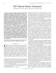
Fig. 3. The expected ratio of energy needed for a TR-based communication<br />
system compared with an L R -finger Rake receiver.<br />
E[r I<br />
] (dB)<br />
−20<br />
−22<br />
−24<br />
−26<br />
−28<br />
−30<br />
−32<br />
−34<br />
−36<br />
E[r I<br />
] vs. L R<br />
simulation (L=100)<br />
theory (L=100)<br />
simulation (L=200)<br />
theory (L=200)<br />
−38<br />
0 5 10 15 20<br />
Number of fingers of the Rake receiver<br />
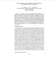
Fig. 4. The expected interference alleviation of a TR-based communication<br />
system compared with an L R -finger Rake receiver.<br />
IV. SIMULATION RESULTS<br />
In this part, we present some simulation results about the<br />
performance of TR transmission, and justify the theoretical<br />
results derived in Section III. Simulation results shown in this<br />
section are obtained by choosing σ T = 125T s in the system<br />
model. We are interested in the impact of L R (number of<br />
fingers of the Rake receiver) and L (number of channel taps)<br />
on the system performance. Because 3GPP2 recommends the<br />
Rake receiver shall provide a minimum of four fingers for the<br />
CDMA 2000 system [16], and too many fingers may result in<br />
unaffordable complexity, we believe comparing the TR-based<br />
transmission with a Rake receiver who has four to eight fingers<br />
is a relative fair comparison.<br />
In Fig. 3, we compare τ P approximated in (29) (denoted<br />
by “theory”) with the value of E[r P ] by averaging r P over<br />
5000 channel realizations. L R is varied from 1 to 20, and L is<br />
chosen from {100, 200, 300}. We can see that, as an analytical<br />
approximation of E[r P ], τ P matches simulation results very<br />
well in a wide range of L R (1 ≤ L R < 15). When there<br />
are fewer fingers in the Rake receiver, direct transmission<br />
can only get a worse equalization. Thus, in order to have<br />
the same receiver performance, direct transmission costs an
1704 IEEE JOURNAL ON SELECTED AREAS IN COMMUNICATIONS, VOL. 29, NO. 8, SEPTEMBER 2011<br />
9<br />
1<br />
E[r P<br />
] vs. L R<br />
8<br />
7<br />
6<br />
equal<br />
D=5<br />
D=10<br />
D=15<br />
0.9<br />
0.8<br />
0.7<br />
P TR / σ 2 (dB)<br />
5<br />
4<br />
3<br />
E[r P<br />
]<br />
0.6<br />
0.5<br />
0.4<br />
indoor<br />
outdoor<br />
2<br />
0.3<br />
1<br />
0.2<br />
0<br />
0 1 2 3 4 5 6 7 8 9<br />
P DT / σ 2 (dB)<br />
Fig. 5. Expected transmit power needed for a TR-based system vs. an L R -<br />
finger Rake receiver (ISI non-negligible).<br />
15<br />
0.1<br />
0 5 10 15 20<br />
Number of fingers of the Rake receiver<br />
Fig. 7. Expected ratio of energy needed for a TR-based system vs. direct<br />
transmission (IEEE 802.15.4a channel model).<br />
−20<br />
E[r I<br />
] vs. L R<br />
10<br />
I DT<br />
I TR<br />
−22<br />
5<br />
−24<br />
I/σ 2 (dB)<br />
0<br />
E[r I<br />
] (dB)<br />
−26<br />
−5<br />
−28<br />
−10<br />
−15<br />
0 2 4 6 8 10 12 14 16 18 20 22<br />
D<br />
Fig. 6. Expected interference alleviation of a TR-based system vs. an L R -<br />
finger Rake receiver (ISI non-negligible).<br />
−30<br />
indoor<br />
outdoor<br />
−32<br />
0 5 10 15 20<br />
Number of fingers of the Rake receiver<br />
Fig. 8. Expected interference alleviation for a TR-based system vs. direct<br />
transmission (IEEE 802.15.4a channel model).<br />
increasing amount of transmission power compared to TR, and<br />
TR becomes more energy-efficient than direct transmission,<br />
reflected by a decreasing E[r P ]. In addition, TR can benefit<br />
more from a richer multi-path environment, as shown by the<br />
decrease in E[r P ] when L increases from 100 to 300.<br />
In Fig. 4, we compare τ I with E[r I ] which is obtained<br />
by averaging r I over 5000 realizations. We can see that the<br />
τ I also matches the simulation results E[r I ] very well. Under<br />
the system model defined in Section II, the interference caused<br />
by TR is 22 dB to 38 dB lower than the interference of direct<br />
transmission, depending on different choices of L R and L.<br />
Under a normal parameter setting, e.g., L = 200 and L R =6,<br />
the interference of TR is about 30 dB lower, which indicates<br />
TR signal transmission can greatly reduce the interference and<br />
is thus much “greener”.<br />
To simplify the analysis of τ P and τ I , we have assumed D<br />
is so large that the ISI becomes negligible in Section III. In<br />
order to better understand the impact of the parameter D on<br />
the transmit power reduction and the interference alleviation,<br />
we use simulations to demonstrate E[r P ] and E[r I ] where the<br />
ISI cannot be neglected in the received signal for both direct<br />
transmission and TR-based transmission. In Fig. 5, we show<br />
the ratio between the transmit signal power required by the<br />
two schemes against the noise power, in order to achieve the<br />
same received SINR performance. For illustration purpose, we<br />
choose L R =6fingers and L =21channel taps. The value<br />
of factor D is chosen from {5, 10, 15} to represent very large,<br />
medium, and small ISI, respectively. The blue line with legend<br />
“equal” is used to represent the benchmark P DT = P TR<br />
for comparing the transmit power of the two schemes. We<br />
see from Fig. 5 that in order to achieve the same receiver<br />
performance, direct transmission usually requires 2∼3 dB<br />
higher transmit power than TR-based transmission. In Fig. 6,<br />
we show the interference power comparison when the transmit<br />
power of the two schemes follows the relation shown in Fig. 5.<br />
We can see that the interference at a victim receiver caused by<br />
TR-based transmission is around 13 dB lower than that caused<br />
by direct transmission, when D varies in [1, 21]. This clearly<br />
shows that the capability of power reduction and interference<br />
alleviation of TR-based transmission remains even if we want<br />
to transmit the signals with a higher data rate, i.e., a smaller<br />
D.
WANG et al.: GREEN WIRELESS COMMUNICATIONS: A TIME-REVERSAL PARADIGM 1705<br />
Bit Error Rate<br />
theory<br />
simulation<br />
10 −1<br />
10 −2<br />
10 −3<br />
10 −4<br />
10 −5<br />
10 −6<br />
−10 −8 −6 −4 −2 0 2 4 6 8 10 12<br />
10 0 P/σ 2 (dB)<br />
V. EXPERIMENTAL MEASUREMENTS<br />
In this part, we demonstrate some experimental measurements<br />
taken in practical multi-path channels. The tested signal<br />
bandwidth spans from 490 MHz to 870 MHz, centered at<br />
the carrier frequency 680 MHz. Two measurement sites are<br />
considered, an office room and a corridor, both of which are<br />
located on the second floor of the J. H. Kim Engineering<br />
Building at the University of Maryland. The layout of the<br />
two sites are given in Fig. 10, where transceiver A transmits<br />
time-reversed signals to transceiver B, and electromagnetic<br />
waves are reflected by walls, ceiling/floor, and other objects<br />
in the surrounding area. We fixed the location of transceiver<br />
A, whereas moving transceiver B in a rectangular area (the<br />
length is about four wave lengths) in the experiment.<br />
Fig. 9.<br />
Illustration of the diversity order using the bit error rate (BER) curve.<br />
In Section II, in order to make the performance analysis<br />
tractable, we have assumed a specific channel model as defined<br />
in eqn. (2). In order to have a more comprehensive comparison<br />
on the performance of TR-based transmission and direct<br />
transmission, we also conduct numerical simulations under<br />
practical channel models. Although 3GPP channel model is<br />
a prevailing channel model, it does not fit in the proposed<br />
TR-based scheme, because 3GPP channel models only apply<br />
to narrow-band systems, while the TR-based scheme requires<br />
a frequency bandwidth of at least several hundred MHz so<br />
as to have a plenty of multipath components. As will be<br />
seen in the next section, the bandwidth in the experimental<br />
measurements actually spans from 490 MHz to 870 MHz. Due<br />
to this reason, we chose the IEEE 802.15.4a channel model<br />
[23] which is a standard model for wideband transmissions,<br />
and simulated both the indoor LOS scenario with L ∼ 100<br />
taps and the outdoor NLOS scenario with L ∼ 500 taps. The<br />
simulation results are shown in Fig. 7 and Fig. 8, where the x-<br />
axis denotes the number of fingers of the Rake receiver varying<br />
from 1 to 20, and the y-axis denotes the expected power<br />
reduction and interference alleviation, respectively. As can be<br />
seen from these figures, compared to direct transmission using<br />
a6-finger Rake receiver, TR-based transmission only needs<br />
62% transmit power while reducing the interference by 23<br />
dB in an indoor environment, and for outdoor, TR only needs<br />
48% transmit power while reducing the interference by 27 dB.<br />
These clearly show the advantage of TR-based scheme over<br />
direct transmission in a practical wireless channel.<br />
Finally, in Fig. 9, we show the multi-path gain of TR, where<br />
the channel length is chosen 5 as L =5and the rate back-off<br />
factor is D =5. We can see that in the high SNR regime, the<br />
diversity order of TR is around 5, which equals L and thus<br />
justifies the derivation in Section III-C.<br />
5 Although the real channel length is generally much longer than the chosen<br />
parameter, computers cannot afford the simulation using real channel length<br />
that requires 10 L channel realizations to get an error bit. Therefore, we choose<br />
a much shorter multi-path channel just for illustration purpose.<br />
A. Channel Impulse Response<br />
In Fig. 11, we show the amplitude of the channel impulse<br />
response (CIR) in the two tested sites. Due to the plentiful<br />
reflections by the walls of the small room, there are more<br />
paths (larger delay spread) for the office environment than<br />
in the corridor. Moreover, the amplitude also decays more<br />
slowly in the office environment, since the signal waveforms<br />
are bounced back and forth and thus last longer in time. In<br />
Fig. 11(c), we show the normalized magnitude of the received<br />
signals using the TR transmission in the corridor. We see<br />
clearly that TR can compress a substantial portion of signal<br />
power into very few taps, i.e., has the temporal focusing effect.<br />
B. Power Reduction<br />
Due to the temporal focusing effect, TR can utilize the<br />
multi-paths as multiple antennas to harvest energy from the<br />
environment. By varying the number of fingers of a Rake<br />
receiver for direct transmission, we show the ratio of the<br />
transmission power of a TR system over direct transmission<br />
in Fig. 12. We can see that in order to achieve the same<br />
receiver performance, TR only costs as low as 30 % of the<br />
transmission power of direct transmission, given that a Rake<br />
receiver usually has less ten fingers, for both the office and<br />
the corridor. When the Rake receiver has six fingers, the<br />
ratio of power reduces to 20 % for the office and 24 % for<br />
the corridor. This shows that TR can achieve highly energyefficient<br />
communication without requiring much complexity<br />
for the transmitter and the receiver. It is worth noting that the<br />
experimental measurement shown here in Fig. 12 has a similar<br />
trend as the case of L = 200 in Fig. 3.<br />
C. Interference Alleviation<br />
Besides energy-efficiency due to the temporal focusing<br />
effect, the time-reversed waves can also retrace the incoming<br />
paths, resulting in a spiky spatial signal power distribution<br />
focused at the intended receiver. This indicates by using TR,<br />
a transmitter will cause little interference to an un-intended<br />
receiver. In this part, we demonstrate the spacial focusing<br />
effect of TR and the resulting interference alleviation. In<br />
the experiment, we used the time-reversed CIR associated<br />
with the intended receiver as a basic waveform to load data<br />
streams, and moved the receive antenna by a step size of λ/2,
1706 IEEE JOURNAL ON SELECTED AREAS IN COMMUNICATIONS, VOL. 29, NO. 8, SEPTEMBER 2011<br />
(a) Layout of the office site<br />
(b) Layout of the corridor site<br />
Fig. 10.<br />
Floor plan and the layout of the test sites.<br />
where λ is the wave length corresponding to carrier frequency<br />
680 MHz.<br />
The received signal power distribution (normalized by the<br />
peak power) in the spatial domain is shown in Fig. 13. We<br />
see that the spike is centered at the intended receiver located<br />
at point (6, 6) for office measurements and (4, 4) for corridor<br />
measurements, whereas the received signal power in the other<br />
locations is only 20 % to 30 % of the signal power in the<br />
intended location. Therefore, it is highly possible that the<br />
interference leakage caused by a transmitter using the TRbased<br />
transmission will be much smaller than that without<br />
using TR. We show the interference ratio r I between TR and<br />
direct transmission in Fig. 14, assuming that the power ratio<br />
r P corresponds to a six-finger Rake receiver. We can see that<br />
on average the interference caused by TR transmission is 3 dB<br />
lower than the interference of direct transmission.<br />
One may notice that the interference alleviation shown here<br />
is not as good as that shown in Fig. 4. The reason is that our<br />
system model assumes ideal channel independence among different<br />
transmission pairs, e.g., when they are very far apart in<br />
space. Thus, the interference shown by the simulation results<br />
is much lower than the results obtained by measurements,<br />
where the channels are actually not perfectly independent<br />
but correlated. However, as shown in Fig. 14, when the unintended<br />
receiver is 2λ (less than 1 m in our experiment) away<br />
from the intended receiver, the least interference caused by TR<br />
transmission can be as low as 6 dB lower, and we can expect<br />
even less severe interference when the un-intended receiver is<br />
farther away. This result demonstrates that TR transmission<br />
has a high resolution of spatial selectivity and low pollution<br />
to the surrounding environment, which makes it a perfect<br />
candidate paradigm for future green wireless communications.<br />
Furthermore, we can observe that the corridor site has better<br />
interference alleviation results than the office site. Because the<br />
office is a more enclosed environment where waves resonate<br />
between walls and lots of objects, the energy dissipates much<br />
slower and the interference is relatively high. Hence, we can<br />
expect further reduction in interference if the communications<br />
take place in the outdoor environment which is an open space.<br />
D. Spectral Efficiency<br />
A prerequisite of TR transmission is that the transmitter<br />
needs to use the time-reversed channel response as the basic<br />
waveform to load data. If the channel is fast fading, then<br />
the receiver needs to continuously transmit short pilot pulses<br />
to the transmitter so that the transmitter can get immediate<br />
CIR. In the worst case, the receiver needs to send pilot<br />
pulses before every transmission attempt of the transmitter,<br />
leading to a spectral efficiency of 50 %. In this part, we<br />
use experiment results to show that the multi-path channel<br />
of an office environment is actually not changing a lot. In
WANG et al.: GREEN WIRELESS COMMUNICATIONS: A TIME-REVERSAL PARADIGM 1707<br />
1<br />
0.5<br />
0.8<br />
0.45<br />
0.6<br />
0.4<br />
Amplitude<br />
0.4<br />
0.2<br />
0<br />
−0.2<br />
−0.4<br />
Power Needed for a TR system<br />
0.35<br />
0.3<br />
0.25<br />
0.2<br />
0.15<br />
−0.6<br />
0.1<br />
−0.8<br />
0.05<br />
−1<br />
0 100 200 300 400 500 600<br />
<strong>Time</strong> (ns)<br />
(a) CIR (office)<br />
0<br />
0 2 4 6 8 10 12 14 16 18 20<br />
The number of fingers in the Rake receiver<br />
(a) r P (office)<br />
0.35<br />
0.25<br />
0.2<br />
0.15<br />
0.3<br />
Amplitude<br />
0.1<br />
0.05<br />
0<br />
−0.05<br />
−0.1<br />
−0.15<br />
Power Needed for a TR system<br />
0.25<br />
0.2<br />
−0.2<br />
0.15<br />
−0.25<br />
Normalized Magnitude<br />
0 100 200 300 400 500 600<br />
<strong>Time</strong> (ns)<br />
1<br />
0.9<br />
0.8<br />
0.7<br />
0.6<br />
0.5<br />
0.4<br />
0.3<br />
0.2<br />
0.1<br />
(b) CIR (corridor)<br />
0<br />
0 500 1000 1500 2000 2500 3000<br />
Taps of Pre−equalized Channels<br />
(c) Temporal focusing effect (corridor)<br />
Fig. 11. Channel impulse responses and temporal focusing effect obtained<br />
from experiments.<br />
this experiment, we measured the channel every one minute,<br />
and a total of 40 channel snapshots were taken and stored.<br />
In the first twenty minutes, the testing environment was kept<br />
static; in the following ten minutes, one experimenter walked<br />
0.1<br />
0 2 4 6 8 10 12 14 16 18 20<br />
The number of fingers in the Rake receiver<br />
(b) r P (corridor)<br />
Fig. 12. Power reduction by the TR-based transmission obtained by the<br />
experiment measurements.<br />
randomly around the receive antenna (about 1.5 m–3 m away);<br />
in the last ten minutes, the experimenter walked very close<br />
to the antenna (within 1.5 m). In other words, snapshots<br />
1–20 correspond to a static environment, snapshots 21–30<br />
correspond to a moderately varying environment, and snapshot<br />
31–40 correspond to a varying environment.<br />
We calculated the correlation coefficient between different<br />
snapshots to gain an idea of how the channel impulse response<br />
varies. Fig. 15 illustrates the correlation matrix for<br />
this experiment, where each grid represents the correlation<br />
between two snapshots, whose indices are given by the x- and<br />
y- coordinates. Most correlation coefficients between static<br />
snapshots (1 to 20) are above 0.95, which implies that the<br />
channel responses are strongly correlated when the testing<br />
environment is static. When the experimenter moved around<br />
the antenna, some rays might be blocked and additional<br />
reflection paths might be introduced. Therefore, the channel<br />
response will vary from its baseline, i.e., the static response.<br />
From our experiment, although the correlation drops when<br />
there are human activities near the antenna (snapshot 21–<br />
30) and becomes even weaker when the experimenter is very
1708 IEEE JOURNAL ON SELECTED AREAS IN COMMUNICATIONS, VOL. 29, NO. 8, SEPTEMBER 2011<br />
1<br />
0<br />
0.8<br />
−1<br />
−2<br />
0.6<br />
dB<br />
−3<br />
0.4<br />
−4<br />
0.2<br />
−5<br />
0<br />
10<br />
8<br />
6<br />
4<br />
4<br />
2<br />
2<br />
0 0<br />
Multiples of λ /2<br />
Multiples of λ /2<br />
(a) Received signal power (office)<br />
6<br />
8<br />
−6<br />
10<br />
8<br />
6<br />
4<br />
Multiples of λ /2<br />
2<br />
0 0<br />
(a) r I (office)<br />
2<br />
4<br />
Multiples of λ /2<br />
6<br />
8<br />
1<br />
0<br />
−1<br />
0.8<br />
−2<br />
0.6<br />
dB<br />
−3<br />
0.4<br />
−4<br />
0.2<br />
0<br />
8<br />
6<br />
4<br />
Multiples of λ /2<br />
2<br />
0<br />
0<br />
(b) Received signal power (corridor)<br />
2<br />
4<br />
Multiples of λ /2<br />
Fig. 13. Spatial focusing effect of the TR-based transmission from the<br />
experiment measurements.<br />
6<br />
8<br />
−5<br />
−6<br />
8<br />
6<br />
4<br />
Multiples of λ /2<br />
2<br />
0<br />
0<br />
(b) r I (corridor)<br />
2<br />
4<br />
Multiples of λ /2<br />
Fig. 14. Interference alleviation by the TR-based transmission obtained by<br />
the experiment measurements.<br />
6<br />
8<br />
close to the antenna (snapshot 31–40), most of the coefficients<br />
are still higher than 0.8. This suggests that good correlation<br />
is maintained even if the environment is varying, and the<br />
achievable spectral efficiency will be much higher than 50 %.<br />
VI. TIME-REVERSAL DIVISION MULTIPLEXING AND<br />
SECURITY<br />
Due to its special features and focusing effect, the TRbased<br />
communications will spark a series of unique wireless<br />
applications, in addition to the low-power low-interference<br />
green communications. In this section, we briefly introduce<br />
two prospective applications based on the TR communication<br />
technology.<br />
A. <strong>Time</strong>-<strong>Reversal</strong> Division Multiplexing<br />
In a multi-user system, different users have to find a way to<br />
share the wireless media. Traditional approaches include time<br />
division multiplexing (TDM), frequency division multiplexing<br />
(FDM), and code division multiplexing (CDM). The recent<br />
advance in multi-input multi-output (MIMO) has brought in a<br />
new multiplexing scheme named spatial division multiplexing<br />
(SDM), where different users can be distinguished by their<br />
channel response vectors due to the equipment of multiple<br />
antennas. In a rich scattering environment, since different<br />
users have different unique multi-path profiles which depend<br />
on their physical locations and TR transmission treats each<br />
path like a virtual antenna, it is possible to utilize multi-path<br />
profiles as a way to distinguish different users, which may<br />
facilitate the multiplexing. Therefore, a new TR-based multiplexing<br />
scheme, time-reversal division multiplexing (TRDM),<br />
for a multiuser downlink system can be developed [18].<br />
The TRDM exploits the nature of the multi-path environment,<br />
utilizes the location-specific signatures between the<br />
base station and multiple users to separate intended signals,<br />
and thus achieves satisfying performance. Furthermore, the<br />
TRDM approach will make possible numerous applications<br />
that require accurately locating the receiver, e.g., automatic<br />
inventory management in a warehouse, and wireless mailbox<br />
where a server could deliver information to a specific office<br />
in a building.
WANG et al.: GREEN WIRELESS COMMUNICATIONS: A TIME-REVERSAL PARADIGM 1709<br />
40<br />
35<br />
30<br />
25<br />
20<br />
15<br />
1<br />
0.95<br />
0.9<br />
0.85<br />
the secret message. Nevertheless, for our proposed TR-based<br />
security, this would no longer be a problem, because the<br />
underlying spreading sequence is not a fixed choice but instead<br />
a location-specific signature. For the intended receiver, the<br />
multi-path channel automatically serves as a decipher that<br />
recovers the original data sent by the transmitter; and for<br />
all other ineligible users at different locations, the signal that<br />
propagates to their receivers would be noise-like and probably<br />
is hidden below the noise floor. Therefore, malicious users are<br />
unable to recover the secret message, because the security is<br />
inherent in the physical layer.<br />
Fig. 15.<br />
10<br />
5<br />
5 10 15 20 25 30 35 40<br />
Correlation of channel responses at different time epochs.<br />
B. <strong>Time</strong>-<strong>Reversal</strong> Based Security<br />
Secret communications have been of critical interest for<br />
quite a long time. Because of the fast technology evolution, a<br />
malicious attacker may easily find some low-cost radio equipments<br />
or easily modify the existing equipments to enable a<br />
potential intrusion. Moreover, wireless networks are extremely<br />
vulnerable to malicious attacks due to the broadcasting nature<br />
of wireless transmission and often a distributed network structure.<br />
As a result, traditional security measures may become<br />
insufficient to protect wireless networks. Therefore, TR-based<br />
communications can be exploited to enhance system security<br />
based on the unique location-specific multi-path profile.<br />
In a rich scattering wireless environment, multiple paths are<br />
formed by numerous surrounding reflectors. For receivers at<br />
different locations, the received waveforms undergo different<br />
reflecting paths and delays, and hence the multi-path profile<br />
can be viewed as a unique location-specific signature. As<br />
this information is only available to the transmitter and the<br />
intended receiver, it is very difficult for other unauthorized<br />
users to infer or forge such a signature. It has been shown<br />
in [20] that even when the eavesdroppers are close to the<br />
target receiver, the received signal strength is much lower<br />
at the eavesdroppers than at the target receiver in an indoor<br />
application, because the received signals are added incoherently<br />
at the eavesdroppers. The security based on multi-path<br />
profiles is two-fold: first, the multi-path profile can be used<br />
to derive a symmetric key for the transmitter-receiver pair,<br />
which protects the secret information from malicious users;<br />
second, the transmitter can employ the TR-based transmission<br />
to hide the information from eavesdroppers, thanks to the<br />
spatial focusing effect.<br />
The scheme is somehow like the direct sequence spread<br />
spectrum (DSSS) based secret communications. In DSSS<br />
communications, the energy of an original data stream is<br />
spread to a much wide spectrum band by using a pseudorandom<br />
sequence, and the signal is hidden below the noise<br />
floor. It is only those who know the pseudo-random sequence<br />
that could recover the original sequence from the noise-like<br />
signals. However, if the pseudo-random sequence has been<br />
leaked to a malicious user, that user is also capable of decoding<br />
0.8<br />
VII. CONCLUSION<br />
In this paper, we argue and show that TR-based transmission<br />
system is an ideal candidate for green wireless communications.<br />
By receiving pilot pulses from the receiver and<br />
sending back the reversed waveforms, the transmitter can<br />
focus energy at the receiver in both spatial and temporal<br />
domains with high resolution, and thus harvest energy from<br />
the environment and cause less interference to other receivers.<br />
We have investigated the system performance, including power<br />
reduction, interference alleviation, and multi-path diversity<br />
gain. The results show that the TR system has a potential of<br />
over an order of magnitude of reduction in power consumption<br />
and interference alleviation, as well as a very high multi-path<br />
diversity gain. Both numerical simulations and experimental<br />
measurements have shown that TR-based transmission can<br />
greatly reduce transmission power consumption and interuser<br />
interference. Moreover, strong channel correlation is also<br />
demonstrated, showing that TR can achieve green wireless<br />
communication with high spectral efficiency even in a timevarying<br />
environment.<br />
ACKNOWLEDGMENT<br />
The authors would like to thank Ziva Corporation and David<br />
Smith for the use of the radio experiment testbed developed<br />
in a prior joint DARPA project.<br />
REFERENCES<br />
[1] M. Fink, C. Prada, F. Wu, and D. Cassereau, “Self focusing in inhomogeneous<br />
media with time reversal acoustic mirrors,” IEEE Ultrasonics<br />
Symposium, vol. 1., pp. 681-686, 1989.<br />
[2] C. Prada, F. Wu, and M. Fink, “The iterative time reversal mirror: A<br />
solution to self-focusing in the pulse echo mode,” J. Acoustic Society<br />
of America, vol. 90, pp. 1119-1129, 1991.<br />
[3] M. Fink, “<strong>Time</strong> reversal of ultrasonic fields. Part I: Basic principles,”<br />
IEEE Trans. Ultrason., Ferroelectr., Freq. Control, vol. 39, no. 5, pp.<br />
555-566, September 1992.<br />
[4] C. Dorme and M. Fink, “Focusing in transmit-receive mode through<br />
inhomogeneous media: The time reversal matched filter approach,” J.<br />
Acoustic Society of America, vol. 98, no. 2, part.1, pp. 1155-1162,<br />
August 1995.<br />
[5] W. A. Kuperman, W. S. Hodgkiss, and H. C. Song, “Phase conjugation<br />
in the ocean: Experimental demonstration of an acoustic time-reversal<br />
mirror,” J. Acoustic Society of America, vol. 103, no. 1, pp. 25-40,<br />
January 1998.<br />
[6] H. C. Song, W. A. Kuperman, W. S. Hodgkiss, T. Akal, and C. Ferla,<br />
“Iterative time reversal in the ocean,” J. Acoustic Society of America,<br />
vol. 105, no. 6, pp. 3176-3184, June 1999.<br />
[7] D. Rouseff, D.R. Jackson, W. L. Fox, C. D. Jones, J. A. Ritcey, and<br />
D. R. Dowling, “Underwater acoustic communication by passive-phase<br />
conjugation: theory and experimental results,” IEEE J. Ocean. Eng.,<br />
vol. 26, pp. 821–831, 2001.
1710 IEEE JOURNAL ON SELECTED AREAS IN COMMUNICATIONS, VOL. 29, NO. 8, SEPTEMBER 2011<br />
[8] B. E. Henty and D. D. Stancil, “Multipath enabled super-resolution<br />
for RF and microwave communication using phase-conjugate arrays,”<br />
Physical Review Letters, vol. 93, no. 24, pp. 243904(4), December 2004.<br />
[9] G. Lerosey, J. de Rosny, A. Tourin, A. Derode, G. Montaldo, and<br />
M. Fink, “<strong>Time</strong> reversal of electromagnetic waves,” Physical Review<br />
Letters, vol. 92, pp. 193904(3), May 2004.<br />
[10] M. Emami, M. Vu, J. Hansen, A. J. Paulraj, and G. Papanicolaou,<br />
“Matched filtering with rate back-off for low complexity communications<br />
in very large delay spread channels,” Proc. 38th Asilomar Conf.<br />
Signals, Syst. Comput., vol. 1, pp. 218–222, Nov. 2004.<br />
[11] Y. Jin and J. M. F. Moura, “<strong>Time</strong> reversal imaging by adaptive<br />
interference canceling,” IEEE Trans. Signal Process., vol. 56, no. 1,<br />
pp. 233-247, January 2008.<br />
[12] J. M. F. Moura and Y. Jin, “Detection by time reversal: single antenna,”<br />
IEEE Trans. Signal Process., vol. 55, no. 1, pp. 187–201, 2007.<br />
[13] Y. Jin and J. M. F. Moura, “<strong>Time</strong> reversal detection using antenna<br />
arrays,” IEEE Trans. Signal Process., vol. 57, no. 4, pp. 1396–1414,<br />
April 2009.<br />
[14] A. J. Goldsmith, <strong>Wireless</strong> Communication, 1st Ed., New York: Cambridge<br />
University, 2005.<br />
[15] A. M. Law, Simulation Modeling and Analysis, 4th Ed., McGraw-Hill<br />
New York, 2007.<br />
[16] 3GPP2, Physical Layer Standard for CDMA2000 Spread Spectrum<br />
Systems, Rev-E, June 2010.<br />
[17] M. K. Simon and M. S. Alouini, “A unified approach to the performance<br />
analysis of digital communication over generalized fading channels,”<br />
Proc. IEEE, vol. 86, no. 9, pp. 1860–1877, Sept. 1998.<br />
[18] F. Han, Y. H. Yang, B. Wang, Y. Wu, and K. J. R. Liu, “<strong>Time</strong>reversal<br />
division multiplexing in multi-path channels,” IEEE Conference<br />
on <strong>Communications</strong> (ICC) 2011, submitted.<br />
[19] P. Blomgren, P. Kyritsi, A. Kim, and G. Papanicolaou, “Spatial focusing<br />
and intersymbol interference in multiple-input-single-output time<br />
reversal communication systems,” IEEE J. Ocean. Eng., vol. 33, no. 3,<br />
pp.341-355, July 2008.<br />
[20] X. Zhou, P. Eggers, P. Kyritsi, J. Andersen, G. Pedersen, and J. Nilsen,<br />
“Spatial focusing and interference reduction using MISO time reversal in<br />
an indoor application,” IEEE Workshop on Statistical Signal Processing<br />
(SSP 2007), pp. 307-311.<br />
[21] Kyungwhoon Cheun, “Performance of direct-sequence spread-spectrum<br />
RAKE receivers with random spreading sequences,” IEEE Trans. Commun.,<br />
vol. 45, no. 9, pp. 1130-1143, Sep. 1997.<br />
[22] D. Tse and P. Viswanath, Fundamentals of <strong>Wireless</strong> Communication,<br />
Cambridge University Press, 2005.<br />
[23] A. F. Molisch, B. Kannan, D. Cassioli, C. C. Chong, S. Emami, A. Fort,<br />
J. Karedal, J. Kunisch, H. Schantz, U. Schuster and K. Siwiak, “IEEE<br />
802.15.4a channel model - final report”, IEEE 802.15-04-0662-00-004a,<br />
San Antonio, TX, USA, Nov. 2004.<br />
Beibei Wang (S’07-M’11) received the B.S. degree<br />
in electrical engineering (with the highest honor)<br />
from the University of Science and Technology of<br />
China, Hefei, in 2004, and the Ph.D. degree in<br />
electrical engineering from the University of Maryland,<br />
College Park in 2009. From 2009 to 2010,<br />
she was a research associate at the University of<br />
Maryland. Currently, she is a senior engineer with<br />
Corporate Research and Development, Qualcomm<br />
Incorporated, San Diego, CA.<br />
Her research interests include wireless communications<br />
and networking, including cognitive radios, dynamic spectrum allocation<br />
and management, network security, and multimedia communications. Dr.<br />
Wang was the recipient of the Graduate School Fellowship, the Future Faculty<br />
Fellowship, and the Dean’s Doctoral Research Award from the University of<br />
Maryland, College Park. She is a coauthor of Cognitive Radio Networking<br />
and Security: A Game-Theoretic View, Cambridge University Press, 2010.<br />
Yongle Wu (S’08) received the Ph.D. degree in<br />
Electrical and Computer Engineering from University<br />
of Maryland, College Park in 2010. He received<br />
the B.S. (with highest honor) and M.S. degrees in<br />
Electronic Engineering from Tsinghua University,<br />
Beijing, China, in 2003 and 2006, respectively.<br />
He is currently a senior engineer with Qualcomm<br />
Incorporated, San Diego, CA.<br />
His research interests are in the areas of wireless<br />
communications and networks, including cognitive<br />
radio techniques, dynamic spectrum access, network<br />
security, and MIMO-OFDM communication systems. Mr. Wu received the<br />
Graduate School Fellowship from the University of Maryland in 2006, the<br />
Future Faculty Fellowship in 2009 and the Litton Industries Fellowship<br />
in 2010, both from A. James Clark School of Engineering, University of<br />
Maryland, and the Distinguished Dissertation Fellowship from Department of<br />
Electrical and Computer Engineering, University of Maryland in 2011.<br />
Feng Han (S’08) received the B.S. and M.S. degrees<br />
in Electronic Engineering from Tsinghua University,<br />
Beijing, China, in 2007 and 2009, respectively. He<br />
is currently pursuing the Ph. D. degree in Electrical<br />
Engineering, at the University of Maryland, College<br />
Park. His current research interests include wireless<br />
communications and networking, smart grid, game<br />
theory, and information theory.<br />
He is a recipient of the first prize in the 19th<br />
Chinese Mathematical Olympiad, the Best Thesis<br />
Award of Tsinghua University, the honor of Excellent<br />
Graduate of Tsinghua University, and the A. James Clark School<br />
of Engineering Distinguished Graduate Fellowship from the University of<br />
Maryland, College Park. He received a Best Paper Award for his work on<br />
MIMO system at IEEE WCNC’08, Las Vegas, NV, in 2008.<br />
2009 and 2010.<br />
Yu-Han Yang (S’06) received his B.S. in electrical<br />
engineering in 2004, and two M.S. degrees in<br />
computer science and communication engineering<br />
in 2007, from National Taiwan University, Taipei,<br />
Taiwan. He is currently pursuing the Ph.D. degree<br />
at the University of Maryland, College Park. His<br />
research interests include wireless communication<br />
and signal processing. He received Class A Scholarship<br />
from National Taiwan University in Fall 2005<br />
and Spring 2006. He is a recipient of Study Abroad<br />
Scholarship from Taiwan (R.O.C.) Government in<br />
K. J. Ray Liu (F’03) is named a Distinguished<br />
Scholar-Teacher of University of Maryland, College<br />
Park, in 2007, where he is Christine Kim Eminent<br />
Professor of Information Technology. He serves as<br />
Associate Chair of Graduate Studies and Research<br />
of Electrical and Computer Engineering Department<br />
and leads the Maryland Signals and Information<br />
Group conducting research encompassing broad aspects<br />
of wireless communications and networking,<br />
information forensics and security, multimedia signal<br />
processing, and biomedical engineering.<br />
Dr. Liu is the recipient of numerous honors and awards including IEEE<br />
Signal Processing Society Technical Achievement Award and Distinguished<br />
Lecturer. He also received various teaching and research recognitions from<br />
University of Maryland including university-level Invention of the Year<br />
Award; and Poole and Kent Senior Faculty Teaching Award and Outstanding<br />
Faculty Research Award, both from A. James Clark School of Engineering.<br />
An ISI Highly Cited Author in Computer Science, Dr. Liu is a Fellow of<br />
IEEE and AAAS.<br />
Dr. Liu is President-Elect and was Vice President - Publications of IEEE<br />
Signal Processing Society. He was the Editor-in-Chief of IEEE Signal<br />
Processing Magazine and the founding Editor-in-Chief of EURASIP Journal<br />
on Advances in Signal Processing.