Green Wireless Communications: A Time-Reversal Paradigm
Green Wireless Communications: A Time-Reversal Paradigm
Green Wireless Communications: A Time-Reversal Paradigm

Create successful ePaper yourself
Turn your PDF publications into a flip-book with our unique Google optimized e-Paper software.
WANG et al.: GREEN WIRELESS COMMUNICATIONS: A TIME-REVERSAL PARADIGM 1703<br />
could be made 20 dB lower by using the TR-based system.<br />
Even for a practical environment where correlation between<br />
channel responses does exist, our experiment measurements<br />
show that the interference alleviation can be up to 6 dB<br />
when the victim receiver is only 1 m away from the intended<br />
receiver. Therefore, the interference caused to an un-intended<br />
receiver with the TR-based transmission is greatly reduced<br />
compared to direct transmission.<br />
E[r P<br />
]<br />
0.6<br />
0.5<br />
0.4<br />
0.3<br />
simulation (L=100)<br />
theory (L=100)<br />
simulation (L=200)<br />
theory (L=200)<br />
simulation (L=300)<br />
theory (L=300)<br />
E[r P<br />
] vs. L R<br />
C. Multi-Path Gain of TR<br />
Since TR can utilize the multi-paths as virtual multiantennas,<br />
the multiple paths can provide spatial diversity.<br />
In this part, we briefly talk about the maximum achievable<br />
diversity order of TR transmission.<br />
We first consider a binary phase-shift keying (BPSK) signaling<br />
with amplitude √ P , i.e., X[k] =± √ P . By omitting<br />
the ISI term, the error probability of detecting X is<br />
(√ ) ⎛<br />
(<br />
P Sig<br />
L−1<br />
) ⎞<br />
Q<br />
σ 2 = Q ⎝√ 2 |h[l]|<br />
/2<br />
2 SNR⎠ , (39)<br />
∑<br />
l=0<br />
where SNR = P/σ 2 is the signal-to-noise ratio per symbol<br />
time, and Q(·) is the complementary cumulative distribution<br />
function of an N(0, 1) random variable. By averaging over<br />
the random tap gain h and following similar analysis as in<br />
[22], we can express the overall error probability as<br />
p e ≤<br />
L−1<br />
∏<br />
l=0<br />
L−1<br />
∏<br />
≤<br />
=<br />
l=0<br />
( L−1 ∏<br />
l=0<br />
(1+SNR · e − lTs<br />
σ T<br />
) −1<br />
(SNR · e − lTs<br />
σ T<br />
) −1<br />
e lTs<br />
σ T<br />
)<br />
(SNR) −L<br />
=e L(L−1)Ts<br />
2σ T (SNR) −L .<br />
(40)<br />
Thus, the maximum achievable diversity of TR-filtering is<br />
L. Similar conclusions can be drawn when other modulation<br />
schemes are used, such as quadrature amplitude modulation<br />
(QAM) and M-ary phase-shift keying (PSK). For example, if<br />
an M-QAM is used, the error probability of a symbol for a<br />
fixed channel can be represented by<br />
0v<br />
0<br />
1 1<br />
0v<br />
0<br />
1 1<br />
L−1<br />
Bu<br />
X<br />
4KQ @ tb @ QAM |h[l]| 2 A C<br />
SNRA − 4K 2 Q 2 L−1<br />
Bu<br />
X<br />
@ tb @ QAM |h[l]| 2 A C<br />
SNRA , (41)<br />
l=0<br />
l=0<br />
where K =1− 1/ √ M and b QAM =3/(M − 1) [17]. Note<br />
that the second term can be dropped because we are interested<br />
in the upper bound, and similar derivation can be applied to<br />
show that the error probability is asymptotically proportional<br />
to (SNR) −L .<br />
We have assumed that multi-paths on different channel taps<br />
are independent, and there are L independent multi-paths in<br />
total, which account for the diversity order of L. In practice,<br />
however, it is possible that some multi-path components on<br />
nearby channel taps are correlated, and there are possibly some<br />
channel taps on which no multi-paths fall in. In that case, we<br />
only consider those independent multi-paths, and according<br />
to our analysis, the diversity order of a TR system should be<br />
equal to the number of independent multi-paths.<br />
0.2<br />
0.1<br />
0<br />
0 5 10 15 20<br />
Number of fingers of the Rake receiver<br />
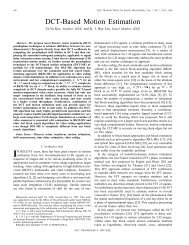
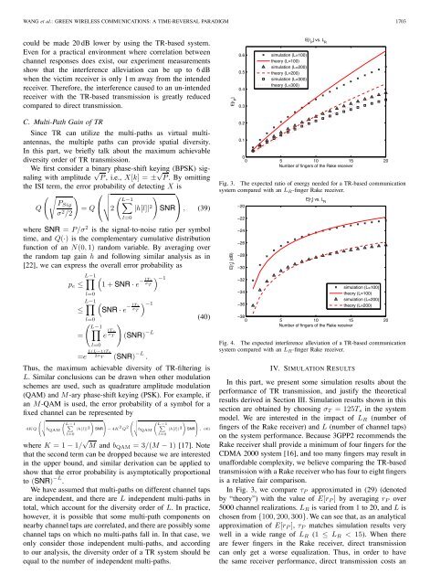
Fig. 3. The expected ratio of energy needed for a TR-based communication<br />
system compared with an L R -finger Rake receiver.<br />
E[r I<br />
] (dB)<br />
−20<br />
−22<br />
−24<br />
−26<br />
−28<br />
−30<br />
−32<br />
−34<br />
−36<br />
E[r I<br />
] vs. L R<br />
simulation (L=100)<br />
theory (L=100)<br />
simulation (L=200)<br />
theory (L=200)<br />
−38<br />
0 5 10 15 20<br />
Number of fingers of the Rake receiver<br />
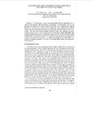
Fig. 4. The expected interference alleviation of a TR-based communication<br />
system compared with an L R -finger Rake receiver.<br />
IV. SIMULATION RESULTS<br />
In this part, we present some simulation results about the<br />
performance of TR transmission, and justify the theoretical<br />
results derived in Section III. Simulation results shown in this<br />
section are obtained by choosing σ T = 125T s in the system<br />
model. We are interested in the impact of L R (number of<br />
fingers of the Rake receiver) and L (number of channel taps)<br />
on the system performance. Because 3GPP2 recommends the<br />
Rake receiver shall provide a minimum of four fingers for the<br />
CDMA 2000 system [16], and too many fingers may result in<br />
unaffordable complexity, we believe comparing the TR-based<br />
transmission with a Rake receiver who has four to eight fingers<br />
is a relative fair comparison.<br />
In Fig. 3, we compare τ P approximated in (29) (denoted<br />
by “theory”) with the value of E[r P ] by averaging r P over<br />
5000 channel realizations. L R is varied from 1 to 20, and L is<br />
chosen from {100, 200, 300}. We can see that, as an analytical<br />
approximation of E[r P ], τ P matches simulation results very<br />
well in a wide range of L R (1 ≤ L R < 15). When there<br />
are fewer fingers in the Rake receiver, direct transmission<br />
can only get a worse equalization. Thus, in order to have<br />
the same receiver performance, direct transmission costs an