Green Wireless Communications: A Time-Reversal Paradigm
Green Wireless Communications: A Time-Reversal Paradigm
Green Wireless Communications: A Time-Reversal Paradigm

Create successful ePaper yourself
Turn your PDF publications into a flip-book with our unique Google optimized e-Paper software.
WANG et al.: GREEN WIRELESS COMMUNICATIONS: A TIME-REVERSAL PARADIGM 1705<br />
Bit Error Rate<br />
theory<br />
simulation<br />
10 −1<br />
10 −2<br />
10 −3<br />
10 −4<br />
10 −5<br />
10 −6<br />
−10 −8 −6 −4 −2 0 2 4 6 8 10 12<br />
10 0 P/σ 2 (dB)<br />
V. EXPERIMENTAL MEASUREMENTS<br />
In this part, we demonstrate some experimental measurements<br />
taken in practical multi-path channels. The tested signal<br />
bandwidth spans from 490 MHz to 870 MHz, centered at<br />
the carrier frequency 680 MHz. Two measurement sites are<br />
considered, an office room and a corridor, both of which are<br />
located on the second floor of the J. H. Kim Engineering<br />
Building at the University of Maryland. The layout of the<br />
two sites are given in Fig. 10, where transceiver A transmits<br />
time-reversed signals to transceiver B, and electromagnetic<br />
waves are reflected by walls, ceiling/floor, and other objects<br />
in the surrounding area. We fixed the location of transceiver<br />
A, whereas moving transceiver B in a rectangular area (the<br />
length is about four wave lengths) in the experiment.<br />
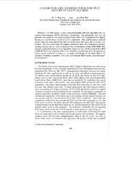
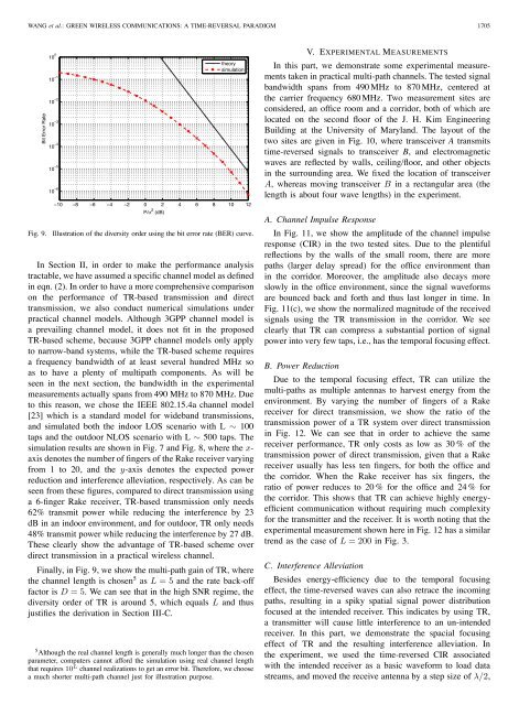
Fig. 9.<br />
Illustration of the diversity order using the bit error rate (BER) curve.<br />
In Section II, in order to make the performance analysis<br />
tractable, we have assumed a specific channel model as defined<br />
in eqn. (2). In order to have a more comprehensive comparison<br />
on the performance of TR-based transmission and direct<br />
transmission, we also conduct numerical simulations under<br />
practical channel models. Although 3GPP channel model is<br />
a prevailing channel model, it does not fit in the proposed<br />
TR-based scheme, because 3GPP channel models only apply<br />
to narrow-band systems, while the TR-based scheme requires<br />
a frequency bandwidth of at least several hundred MHz so<br />
as to have a plenty of multipath components. As will be<br />
seen in the next section, the bandwidth in the experimental<br />
measurements actually spans from 490 MHz to 870 MHz. Due<br />
to this reason, we chose the IEEE 802.15.4a channel model<br />
[23] which is a standard model for wideband transmissions,<br />
and simulated both the indoor LOS scenario with L ∼ 100<br />
taps and the outdoor NLOS scenario with L ∼ 500 taps. The<br />
simulation results are shown in Fig. 7 and Fig. 8, where the x-<br />
axis denotes the number of fingers of the Rake receiver varying<br />
from 1 to 20, and the y-axis denotes the expected power<br />
reduction and interference alleviation, respectively. As can be<br />
seen from these figures, compared to direct transmission using<br />
a6-finger Rake receiver, TR-based transmission only needs<br />
62% transmit power while reducing the interference by 23<br />
dB in an indoor environment, and for outdoor, TR only needs<br />
48% transmit power while reducing the interference by 27 dB.<br />
These clearly show the advantage of TR-based scheme over<br />
direct transmission in a practical wireless channel.<br />
Finally, in Fig. 9, we show the multi-path gain of TR, where<br />
the channel length is chosen 5 as L =5and the rate back-off<br />
factor is D =5. We can see that in the high SNR regime, the<br />
diversity order of TR is around 5, which equals L and thus<br />
justifies the derivation in Section III-C.<br />
5 Although the real channel length is generally much longer than the chosen<br />
parameter, computers cannot afford the simulation using real channel length<br />
that requires 10 L channel realizations to get an error bit. Therefore, we choose<br />
a much shorter multi-path channel just for illustration purpose.<br />
A. Channel Impulse Response<br />
In Fig. 11, we show the amplitude of the channel impulse<br />
response (CIR) in the two tested sites. Due to the plentiful<br />
reflections by the walls of the small room, there are more<br />
paths (larger delay spread) for the office environment than<br />
in the corridor. Moreover, the amplitude also decays more<br />
slowly in the office environment, since the signal waveforms<br />
are bounced back and forth and thus last longer in time. In<br />
Fig. 11(c), we show the normalized magnitude of the received<br />
signals using the TR transmission in the corridor. We see<br />
clearly that TR can compress a substantial portion of signal<br />
power into very few taps, i.e., has the temporal focusing effect.<br />
B. Power Reduction<br />
Due to the temporal focusing effect, TR can utilize the<br />
multi-paths as multiple antennas to harvest energy from the<br />
environment. By varying the number of fingers of a Rake<br />
receiver for direct transmission, we show the ratio of the<br />
transmission power of a TR system over direct transmission<br />
in Fig. 12. We can see that in order to achieve the same<br />
receiver performance, TR only costs as low as 30 % of the<br />
transmission power of direct transmission, given that a Rake<br />
receiver usually has less ten fingers, for both the office and<br />
the corridor. When the Rake receiver has six fingers, the<br />
ratio of power reduces to 20 % for the office and 24 % for<br />
the corridor. This shows that TR can achieve highly energyefficient<br />
communication without requiring much complexity<br />
for the transmitter and the receiver. It is worth noting that the<br />
experimental measurement shown here in Fig. 12 has a similar<br />
trend as the case of L = 200 in Fig. 3.<br />
C. Interference Alleviation<br />
Besides energy-efficiency due to the temporal focusing<br />
effect, the time-reversed waves can also retrace the incoming<br />
paths, resulting in a spiky spatial signal power distribution<br />
focused at the intended receiver. This indicates by using TR,<br />
a transmitter will cause little interference to an un-intended<br />
receiver. In this part, we demonstrate the spacial focusing<br />
effect of TR and the resulting interference alleviation. In<br />
the experiment, we used the time-reversed CIR associated<br />
with the intended receiver as a basic waveform to load data<br />
streams, and moved the receive antenna by a step size of λ/2,