Green Wireless Communications: A Time-Reversal Paradigm
Green Wireless Communications: A Time-Reversal Paradigm
Green Wireless Communications: A Time-Reversal Paradigm

You also want an ePaper? Increase the reach of your titles
YUMPU automatically turns print PDFs into web optimized ePapers that Google loves.
1704 IEEE JOURNAL ON SELECTED AREAS IN COMMUNICATIONS, VOL. 29, NO. 8, SEPTEMBER 2011<br />
9<br />
1<br />
E[r P<br />
] vs. L R<br />
8<br />
7<br />
6<br />
equal<br />
D=5<br />
D=10<br />
D=15<br />
0.9<br />
0.8<br />
0.7<br />
P TR / σ 2 (dB)<br />
5<br />
4<br />
3<br />
E[r P<br />
]<br />
0.6<br />
0.5<br />
0.4<br />
indoor<br />
outdoor<br />
2<br />
0.3<br />
1<br />
0.2<br />
0<br />
0 1 2 3 4 5 6 7 8 9<br />
P DT / σ 2 (dB)<br />
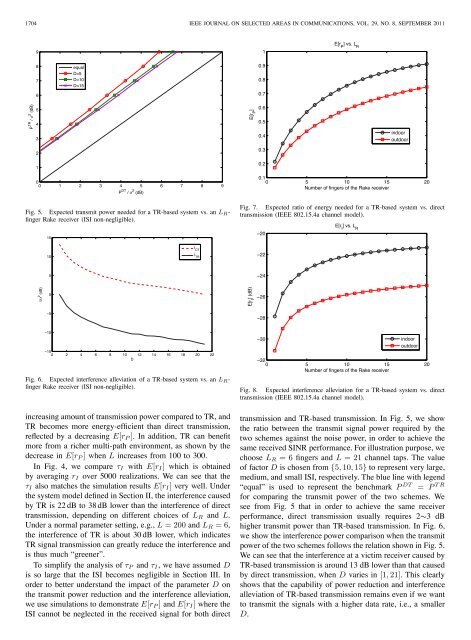
Fig. 5. Expected transmit power needed for a TR-based system vs. an L R -<br />
finger Rake receiver (ISI non-negligible).<br />
15<br />
0.1<br />
0 5 10 15 20<br />
Number of fingers of the Rake receiver<br />
Fig. 7. Expected ratio of energy needed for a TR-based system vs. direct<br />
transmission (IEEE 802.15.4a channel model).<br />
−20<br />
E[r I<br />
] vs. L R<br />
10<br />
I DT<br />
I TR<br />
−22<br />
5<br />
−24<br />
I/σ 2 (dB)<br />
0<br />
E[r I<br />
] (dB)<br />
−26<br />
−5<br />
−28<br />
−10<br />
−15<br />
0 2 4 6 8 10 12 14 16 18 20 22<br />
D<br />
Fig. 6. Expected interference alleviation of a TR-based system vs. an L R -<br />
finger Rake receiver (ISI non-negligible).<br />
−30<br />
indoor<br />
outdoor<br />
−32<br />
0 5 10 15 20<br />
Number of fingers of the Rake receiver<br />
Fig. 8. Expected interference alleviation for a TR-based system vs. direct<br />
transmission (IEEE 802.15.4a channel model).<br />
increasing amount of transmission power compared to TR, and<br />
TR becomes more energy-efficient than direct transmission,<br />
reflected by a decreasing E[r P ]. In addition, TR can benefit<br />
more from a richer multi-path environment, as shown by the<br />
decrease in E[r P ] when L increases from 100 to 300.<br />
In Fig. 4, we compare τ I with E[r I ] which is obtained<br />
by averaging r I over 5000 realizations. We can see that the<br />
τ I also matches the simulation results E[r I ] very well. Under<br />
the system model defined in Section II, the interference caused<br />
by TR is 22 dB to 38 dB lower than the interference of direct<br />
transmission, depending on different choices of L R and L.<br />
Under a normal parameter setting, e.g., L = 200 and L R =6,<br />
the interference of TR is about 30 dB lower, which indicates<br />
TR signal transmission can greatly reduce the interference and<br />
is thus much “greener”.<br />
To simplify the analysis of τ P and τ I , we have assumed D<br />
is so large that the ISI becomes negligible in Section III. In<br />
order to better understand the impact of the parameter D on<br />
the transmit power reduction and the interference alleviation,<br />
we use simulations to demonstrate E[r P ] and E[r I ] where the<br />
ISI cannot be neglected in the received signal for both direct<br />
transmission and TR-based transmission. In Fig. 5, we show<br />
the ratio between the transmit signal power required by the<br />
two schemes against the noise power, in order to achieve the<br />
same received SINR performance. For illustration purpose, we<br />
choose L R =6fingers and L =21channel taps. The value<br />
of factor D is chosen from {5, 10, 15} to represent very large,<br />
medium, and small ISI, respectively. The blue line with legend<br />
“equal” is used to represent the benchmark P DT = P TR<br />
for comparing the transmit power of the two schemes. We<br />
see from Fig. 5 that in order to achieve the same receiver<br />
performance, direct transmission usually requires 2∼3 dB<br />
higher transmit power than TR-based transmission. In Fig. 6,<br />
we show the interference power comparison when the transmit<br />
power of the two schemes follows the relation shown in Fig. 5.<br />
We can see that the interference at a victim receiver caused by<br />
TR-based transmission is around 13 dB lower than that caused<br />
by direct transmission, when D varies in [1, 21]. This clearly<br />
shows that the capability of power reduction and interference<br />
alleviation of TR-based transmission remains even if we want<br />
to transmit the signals with a higher data rate, i.e., a smaller<br />
D.