Calibration and Usage Manual - DFRobot
Calibration and Usage Manual - DFRobot
Calibration and Usage Manual - DFRobot

You also want an ePaper? Increase the reach of your titles
YUMPU automatically turns print PDFs into web optimized ePapers that Google loves.
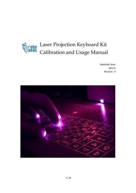
Laser Projection Keyboard Kit<br />
<strong>Calibration</strong> <strong>and</strong> <strong>Usage</strong> <strong>Manual</strong><br />
RoboPeak Team<br />
2013-4<br />
Revision: 0<br />
1 / 21
Catalog:<br />
Catalog: ................................................................................................................................. 2<br />
1. Introduction ............................................................................................................................ 3<br />
1.1. Working Mechanism ......................................................................................... 3<br />
2. <strong>Calibration</strong> <strong>and</strong> Tuning ......................................................................................................... 5<br />
2.1. Basic Power-On Check ...................................................................................... 5<br />
2.2. Connecting with the Signal Processing Software ............................................ 5<br />
2.3. Camera Focus Adjustment ................................................................................ 7<br />
2.4. Calibrating the Projected Keyboard Pattern .................................................... 8<br />
2.5. Camera Angle Adjustment ............................................................................... 9<br />
2.6. Linear Laser Adjustment ................................................................................. 11<br />
2.6.1. Adjusting the laser head ................................................................................. 11<br />
2.6.2. Height adjustment .......................................................................................... 14<br />
2.7. Final <strong>Calibration</strong> .............................................................................................. 14<br />
3. <strong>Usage</strong> of the Signal Processing Software .......................................................................... 16<br />
3.1. Camera Selection ............................................................................................ 16<br />
3.2. the Working UI ................................................................................................ 16<br />
3.3. Multi-language Support ................................................................................. 17<br />
3.4. Keyboard Mode .............................................................................................. 17<br />
3.5. Multi-touch Pad Moe ..................................................................................... 18<br />
3.6. <strong>Calibration</strong> Mode ............................................................................................ 18<br />
3.7. Comm<strong>and</strong> Lines .............................................................................................. 19<br />
3.8. Parameter Tuning ........................................................................................... 19<br />
3.8.1. The exposure value of the camera ................................................................. 20<br />
3.8.2. Key stroke delay <strong>and</strong> repeating interval ........................................................ 20<br />
4. Source-code <strong>and</strong> Documents .............................................................................................. 21<br />
2 / 21
1. Introduction<br />
The Laser Projection Keyboard Kit is based on the open-source laser keyboard project designed<br />
by RoboPeak Team. After a few quick <strong>and</strong> simple assembly <strong>and</strong> calibration process, your laser<br />
projection keyboard is ready to work!<br />
The laser keyboard works just like a st<strong>and</strong>ard keyboard on your PC/MAC with the help of the<br />
related signal processing software designed by RoboPeak. The signal processing software also<br />
supports turning your laser keyboard kit into a multi-touch pad.<br />
As an open-source project, you can freely make any changes/improvement to the current design<br />
<strong>and</strong> go through the implementation detail of the kit.<br />
1.1. Working Mechanism<br />
The Laser Projection Keyboard kit contains the following 3 major key parts: an infrared light<br />
camera, a keyboard pattern projector <strong>and</strong> a linear laser.<br />
Infrared Light<br />
Camera<br />
Keyboard Pattern<br />
Projector<br />
Linear Laser<br />
The keyboard pattern projector displays a virtual keyboard pattern on a flat surface, such as a<br />
desktop surface. When a user touches virtual keys using his/her fingers, the top of fingers will be<br />
illuminated by the lighting plane created by the linear laser. Since the infrared light is used, the<br />
user won’t notice his/her fingers are illuminated.<br />
3 / 21
P’(x’, y’)<br />
Camera<br />
Laser<br />
P(x, y)<br />
Figure: Detect the position of the fingers using triangulation<br />
The infrared light camera captures the images of the illuminated fingers, <strong>and</strong> sends the images to<br />
the signal processing software. The position of the illuminated fingers is detected <strong>and</strong> localized by<br />
the software, <strong>and</strong> it will be transformed to the related key input events.<br />
P x<br />
O(0,0)<br />
Laser<br />
O’(0,0)<br />
P’ x<br />
P’ y<br />
P y<br />
Figure: Mapping the desktop based finger position P(x,y) to the keyboard layout based<br />
coordination <strong>and</strong> generating key events<br />
4 / 21
2. <strong>Calibration</strong> <strong>and</strong> Tuning<br />
You need to calibrate <strong>and</strong> tune your laser projection keyboard in the first use after assembly. A<br />
good calibration <strong>and</strong> tuning will make your laser projection keyboard perform well.<br />
This chapter will guide you through these processes.<br />
2.1. Basic Power-On Check<br />
After finishing assembling the laser projection keyboard kit, please use a micro-usb cable to<br />
connect the kit with a PC/Mac. If everything works fine, you will see the projected keyboard<br />
pattern on the desk surface <strong>and</strong> the PC/Mac will prompt you a new camera device has been<br />
connected.<br />
If you have noticed these, it means the assembly should be succeeded <strong>and</strong> you can continue to<br />
do the calibration job. Otherwise, please review the assembly manual to have further check.<br />
Figure: Windows prompts a camera device is connected when connect the kit with the PC<br />
2.2. Connecting with the Signal Processing Software<br />
The signal processing software designed by RoboPeak team has been included in this kit. The<br />
software processes the input video signal <strong>and</strong> transforms it to the related keyboard input events.<br />
Also, the software will guide you during the calibration <strong>and</strong> tuning processes.<br />
You can download the software via the <strong>DFRobot</strong> official website or from the official website of<br />
RoboPeak team. The software supports both Windows <strong>and</strong> MacOS(Intel x64 only) platforms <strong>and</strong><br />
no pre-installation is required.<br />
To run the software, simply double click the file named laser_kbd.exe (or laser_kbd.app on<br />
MacOS) as shown in the following figure. If it doesn’t work, please contact RoboPeak.<br />
5 / 21
Figure: Running the software (Windows)<br />
Before running the software, please make sure the laser keyboard kit has been connected to your<br />
PC/Mac via the USB cable. You should see the following window when the software is started.<br />
Please select the camera named: Vimicro USB Camera(Altair) using the left/right arrow buttons.<br />
(If there have been similar cameras connected to your machine before, the name may be<br />
altered.)<br />
Figure: the Camera Selection Window<br />
Press the button<br />
to proceed. If everything works well, you will see the following window:<br />
6 / 21
Figure: The working UI of the signal processing software<br />
The upper-left corner of the window displays the image captured from the infrared light camera.<br />
The upper-right corner shows the detected finger position. The software will enter the calibration<br />
mode automatically during the first use.<br />
2.3. Camera Focus Adjustment<br />
You may need to adjust the infrared light camera’s focus in order to make it capture clear images<br />
of the finger input events. Please watch the camera image displayed on the signal processing<br />
software’s window. If you find the image is like the left side of the following figure, you need to<br />
re-focus the camera.<br />
Not focused, the image is blurred<br />
<br />
Correctly focused, the image is clear<br />
Please adjust the focus by tuning the camera lens <strong>and</strong> watch the images displayed on the signal<br />
processing software windows. When you see a clear image of the finger top, the focus<br />
adjustment is finished.<br />
7 / 21
2.4. Calibrating the Projected Keyboard Pattern<br />
Please check the projected keyboard pattern on your desktop. A good projection image should<br />
look like the first figure below. If you find the projected image looks like one of the following<br />
distorted sample image below, you need to tune the pattern projector.<br />
8 / 21
A Good projected<br />
keyboard pattern<br />
image<br />
The left side is<br />
distorted<br />
The right side is<br />
distorted<br />
The bottom of the<br />
image is distorted<br />
The top of the<br />
image is distorted<br />
< 图 > 微 调 螺 丝 照 片<br />
2.5. Camera Angle Adjustment<br />
The infrared light camera should capture the whole area of the projected keyboard pattern image<br />
on the desktop. The signal processing software can be used to help you adjust the camera field of<br />
9 / 21
view angle if necessary.<br />
Please place your finger on the 4 corner of the projected keyboard pattern image on the desktop<br />
one-by-one <strong>and</strong> check whether the illuminated finger top has been captured by the camera.<br />
If you cannot find the illuminated finger shown on the software window, please use the extra<br />
screw pad provided in the kit to make adjustment.<br />
10 / 21
The related illuminated finger top image is recommended to be displayed in the areas like the<br />
following figure<br />
Finger positions<br />
Related image<br />
2.6. Linear Laser Adjustment<br />
The line strip generated by the linear laser should be closely cover to desktop <strong>and</strong> be parallel with<br />
desk surface to make the laser keyboard work.<br />
2.6.1. Adjusting the laser head<br />
When the linear laser beam isn’t parallel with the desk surface (as following figure depicts), you<br />
need to adjust the laser head by tuning it.<br />
11 / 21
As the linear laser generates infrared laser which is invisible to human eyes. You need the help of<br />
the signal processing software.<br />
Please prepare a square box with white color (like the below figure) <strong>and</strong> place it in front of the<br />
laser keyboard. Make sure it is parallel with the projected keyboard pattern:<br />
Then check the image on the signal processing software window. If the linear laser beam is<br />
parallel with the desktop, you will see a horizontal linear light pattern on the image. Otherwise,<br />
you will get a tilted linear light pattern or the pattern is incomplete.<br />
12 / 21
A horizontal linear light pattern<br />
means the linear laser beam is<br />
parallel with the desktop<br />
A tilted linear light pattern<br />
means the linear laser beam is<br />
not parallel with the desktop<br />
An incomplete linear light<br />
pattern means the linear laser<br />
beam is not parallel with the<br />
desktop<br />
You can adjust the angle of the linear laser beam by tuning the head of the linear laser like the<br />
following figure:<br />
13 / 21
2.6.2. Height adjustment<br />
The generated linear laser beam should be kept close to the desktop enough in order to let the<br />
laser keyboard generate precise key input events. If the laser beam is too high, the laser keyboard<br />
will falsely generate key events for those fingers not touching the desktop. If the laser beam is<br />
too close to the desktop, the desktop may be illuminated <strong>and</strong> a false key input event will be<br />
generated as well.<br />
suitable height<br />
<br />
Laser beam is too high<br />
from the desktop.<br />
<br />
Laser beam is too<br />
close to the desktop<br />
The height of the linear laser beam can be adjusted via the adjustment screw.<br />
图 : 激 光 器 微 调 螺 丝<br />
<br />
<br />
2.7. Final <strong>Calibration</strong><br />
It is the last step of the calibration process. After this step, your laser projection keyboard will<br />
work. The signal processing software will help you to complete this step. The software will<br />
prompt you to place your fingers to the point by flashed the related key button:<br />
14 / 21
After placing your finger to the required place, please don’t move the finger. Use mouse to click<br />
the light blob that is related to your finger:<br />
You will be asked to repeat the above steps several times. After about 10 “key pressing”, the<br />
calibration process is completed. The calibration data is stored in the software folder for next<br />
uses. You don’t need to recalibrate your laser keyboard as long as the laser keyboard structure<br />
won’t be changed.<br />
The software will enter keyboard mode when the calibration is finished. In this mode you can use<br />
your laser projection keyboard just as a normal keyboard device.<br />
15 / 21
3. <strong>Usage</strong> of the Signal Processing Software<br />
The signal processing software is specifically designed to be used together with the laser<br />
projection keyboard kit by RoboPeak team. Besides the st<strong>and</strong>ard keyboard input feature, the<br />
software also supports turning the laser keyboard kit into a multi-touch pad which tracks up to 10<br />
points at the same time.<br />
The software also provides calibration features for users to calibrate the keyboard.<br />
The software is softwared, you can download its source code <strong>and</strong> new updates submitted by<br />
RoboPeak.<br />
3.1. Camera Selection<br />
The software allows you to select a camera that is used by the laser keyboard kit when multiple<br />
cameras have been connected to your machine.<br />
After the software is started, it shows the camera selection window. For the laser projection<br />
keyboard kit, the camera should be named with: Vimicro USB Camera(Altair). The software<br />
remembers your choice <strong>and</strong> the related camera will be selected by default in the next software<br />
launch.<br />
3.2. the Working UI<br />
The following working UI window will be appear when the camera has been connected.<br />
16 / 21
Working mode switching<br />
Raw Camera Input<br />
Desktop Coordination Mapping<br />
detected finger blob<br />
Keyboard Mapping<br />
3.3. Multi-language Support<br />
The software supports English <strong>and</strong> Chinese as its UI languages. The related language will be<br />
selected automatically based on the current UI language setting of your machine’s OS.<br />
3.4. Keyboard Mode<br />
The Keyboard Mode is the default working mode of the software. After the calibration has been<br />
done, the software will switch to this mode as well.<br />
The detected user key input events will be injected to the OS in this mode. It supports multiple<br />
key stroke <strong>and</strong> auto repeat features.<br />
NOTE: the key events will be sent to the signal processing software’s window as well when the<br />
window is active. The software will quit when you press the ESC button.<br />
17 / 21
3.5. Multi-touch Pad Moe<br />
When in this mode, the software supports up to 10 points’ multi input sketch pad. Move your<br />
fingers in the areas of the projected keyboard pattern image, <strong>and</strong> you will see your masterpiece<br />
displayed on the sketchpad window.<br />
The sketch image can be cleared by right clicking the mouse.<br />
3.6. <strong>Calibration</strong> Mode<br />
The calibration mode can be entered any time when you need to calibrate your keyboard. The<br />
quality of a calibration will greatly affect the keyboard performance.<br />
Once entering the calibration mode, the software will guide you to perform the calibration<br />
process. You can also refer to the section 3.6 of this document for details.<br />
18 / 21
3.7. Comm<strong>and</strong> Lines<br />
You can change the default behavior of the software by specifying comm<strong>and</strong> line arguments to<br />
the software. Use the –help parameter to see all the available options.<br />
The following comm<strong>and</strong> line format is used:<br />
laser_kbd [options] [camera id]<br />
Options Descriptions Example<br />
-m<br />
Default working mode<br />
Available values:<br />
calib<br />
Keyboard<br />
Entering the multi touch pad mode when the<br />
software started:<br />
laserkdb –m sketch<br />
sketch<br />
Camera id<br />
Make the software to connect the second<br />
The camera to be<br />
camera of the system without display the<br />
connected without<br />
camera selection window:<br />
prompting. Starts<br />
laserkdb 1<br />
form 0<br />
3.8. Parameter Tuning<br />
• Window Users:<br />
The software will read the file named config/general.txt under the same folder where the<br />
software locates.<br />
• Mac Users:<br />
The software will read the file under the user’s home folder with the path:<br />
~/Library/rp_laserkbd/config/general.txt<br />
19 / 21
Users can change the configurations inside this file for extra tuning.<br />
3.8.1. The exposure value of the camera<br />
The software will disable the auto-exposure feature of the camera to work correctly. The<br />
exposure value will be set to a fix value. You can modify this value when you think the current<br />
exposure is not suitable for your keyboard.<br />
exposure_level = -7<br />
You can reference to the following figures to determine which exposure value is suitable for you.<br />
<br />
<br />
<br />
suitable exposure value<br />
Only the finger top parts<br />
is sensed by the camera<br />
under-exposure. The<br />
sensed finger top is too<br />
small<br />
Over-exposure. The<br />
sensed finger top areas<br />
are mixed up.<br />
3.8.2. Key stroke delay <strong>and</strong> repeating interval<br />
You can modified the general.txt to change the intervals of key stroke delay <strong>and</strong> repeating:<br />
keyrefire_delay = 1000<br />
keyrefire_interval = 100<br />
The values are measured in the unit of millisecond (ms).<br />
20 / 21
4. Source-code <strong>and</strong> Documents<br />
Please visit the official website of RoboPeak team for the details of the openosource laser<br />
projection keyboard design.<br />
The related source code can be obtained via Github:<br />
URL:https://github.com/robopeak/laserkbd<br />
21 / 21