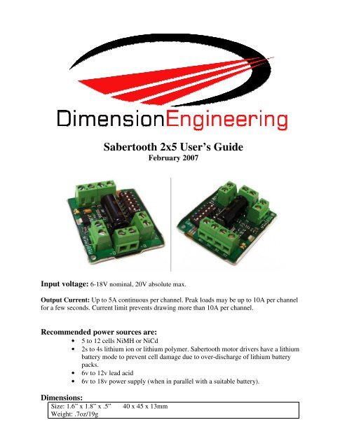
Sabertooth 2x5.pdf - Dimension Engineering
Sabertooth 2x5.pdf - Dimension Engineering
Sabertooth 2x5.pdf - Dimension Engineering

Create successful ePaper yourself
Turn your PDF publications into a flip-book with our unique Google optimized e-Paper software.
FeaturesMixed and independent options:<strong>Sabertooth</strong> features mixed modes designed especially for differential drive robots, where twomotors provide both steering and propulsion. It also has independent options in all operatingmodes. This is useful for if you have two motors to control, but they aren’t necessarily beingused to drive a differential drive robot. The motors do not need to be matched or even similar, aslong as they both are within <strong>Sabertooth</strong>’s operating limits.Synchronous regenerative drive:Going one step farther than just regenerative braking, a <strong>Sabertooth</strong> motor driver will returnpower to the battery any time a deceleration or motor reversal is commanded. This can lead todramatic improvements in run time for systems that stop or reverse often, like a placement robotor a vehicle driving on hilly terrain. This drive scheme also saves power by returning theinductive energy stored in the motor windings to the battery each switching cycle, instead ofburning it as heat in the motor windings. This makes part-throttle operation very efficient.Ultra-sonic switching frequency:<strong>Sabertooth</strong> 2x5 features a PWM frequency of 32kHz, which is well above the maximumfrequency of human hearing. Unlike some other motor drivers, there is no annoying whine whenthe motor is on, even at low power levels.Thermal and overcurrent protection:<strong>Sabertooth</strong> features a temperature sensor and overcurrent sensing. It will protect itself fromfailure due to overheating, overloading and short circuits.Easy mounting and setup:<strong>Sabertooth</strong> has screw terminals for all inputs and outputs. There are two mounting holes, whichaccept 2-56 screws. Mounting hardware is included. All operating modes and options are setwith DIP switches – there are no jumpers to struggle with or lose. No soldering is required.Compact Size:<strong>Sabertooth</strong> utilizes surface mount construction to provide the most power from a compactpackage. Its small size and light weight means you have more space for cargo, batteries, or canmake your robot smaller and more nimble than the competition.Carefree reversing:Unlike some other motor drivers, there is no need for the <strong>Sabertooth</strong> to stop before beingcommanded to reverse. You can go from full forward immediately to full reverse or vice versa.Braking and acceleration are proportional to the amount of reversal commanded, so gentle orrapid reversing is possible.Many operating modes:With analog, R/C and serial input modes, as well as dozens of operating options, the <strong>Sabertooth</strong>has the flexibility to be used over and over, even as your projects grow more sophisticated. Yet itis simple enough to use for your first robot project.
Hooking up the <strong>Sabertooth</strong> motor driverAll connections to the <strong>Sabertooth</strong> are done with screw terminals. This makes it easy to set up andreconfigure your project. If you’ve never used screw terminal connections before, here is a quickoverview.Step 1: Strip the wire which you are usingapproximately ¼” The wires may be 14 gaugeto 30 gaugeStep 2: With a small screwdriver, turn the topscrew counter-clockwise until it stops gently.Step 3: Insert the stripped portion of the wireinto the opening in the screw terminalStep 4: Turn the top screw clockwise untilyou encounter resistance, then tighten thescrew firmly. Pull on the wire gently to ensurethat it is secured.
Motor1 TerminalsMotor 1 is connected to terminals M1A andM1B as shown at right. If the motor runs inthe opposite way that you want, you mayreverse the motor wires to reverse rotation.Motor 2 is connected to terminals M2A andM2BThe motors connect to terminals M1A/B andM2A/BSignal Input TerminalsS1 and S2The input signals that control the <strong>Sabertooth</strong>are connected to terminals S1 and S2. If youare running in analog mode, it is important tohave both the signal inputs connected beforeapplying power to the device. Otherwise, themotors may start unexpectedly.The input signals connect to terminal S1 and/or S2Battery TerminalsB+ and B-The battery or power supply is connected toterminals B- and B+. B- connects to thenegative side of the battery (usually black.)B+ connects to the positive side of the battery(usually red or yellow.) It is usually best toconnect the battery through a connectorinstead of directly to the motor driver. This The battery connects to terminals B+ and B-makes it easy to unplug the battery for charging, and prevents plugging in the battery backwards.Warning! Be very careful to wire and plug in the battery andconnector correctly. Connecting the battery backwards will destroythe <strong>Sabertooth</strong> and will void the warranty.
Power terminals0V and 5VThe 0V and 5V connections areused to power and interface tolow-power control circuits.The 5V connection is a 5vpower output. This is usefulfor supplying power to lowcurrentdevices, such as apotentiometer or a radioreceiver. The 5v terminal iscapable of supplying 100The 5V terminal can be used to power small loads, like apotentiometer or a radio receiver. The 0V signal must beconnected to the ground of the device generating the inputsignal.milliamps if the source battery is 12.6v or less. If the source battery is greater than 12.6 volts, the5v terminal is capable of supplying 10 milliamps. If more power is needed, we recommend usinga ParkBEC or DESW050 to supply the needed 5V power to the rest of the robot.The 0V connection is the signal ground for the <strong>Sabertooth</strong>. In order to receive input signalscorrectly, it must be connected to the ground of the device sending the signals.Using the 0V and 5v connections to power a radio receiver in R/C mode and potentiometer inanalog mode is shown in Figures 2.1 and 2.2. If you are using multiple <strong>Sabertooth</strong> 2x5s runningfrom the same radio receiver, only one should have the 5v line connected.Figure 2.1: Analog input using a potentiometerpowered from terminal 5VFigure 2.2: R/C input using a receiver poweredfrom terminal 5V
Status and Error LEDs<strong>Sabertooth</strong> 2x5 has two indicator LEDs.The blue LED is used to communicate variousinformation about the current state. In mostcases Status1 acts as a power indicator. In R/Cmode, it glows dimly if there is no RC linkpresent and brightly if there is an RC link. Inlithium mode, the blue LED will blink out thenumber of lithium cells detected.The red LED illuminates if the <strong>Sabertooth</strong> hasStatus LED ondetected a problem. It will light if the driver hasshut down due to a depleted battery or due to overheating or overcurrent. If you are using a NiCdor NiMH battery, and commanding an acceleration causes the motor to jerk and the Error LED toflash on and off, the battery is depleted.Mounting your <strong>Sabertooth</strong> 2x5The <strong>Sabertooth</strong> is supplied with two mounting holes. Thesecan be used to attach it to your robot. The centers of themounting holes form a 1.25” x 1.5” rectangle. The holesare .09” inches in diameter. The proper size screw is a 2-56round head machine or wood screw. two 1/2” long machinescrews and nuts are included.If your robot or device is constructed from insulatingmaterials such as wood or plastic and you are runnin, itmay be necessary to mount the <strong>Sabertooth</strong> on standoffs toallow air to circulate. This is shown in Figure 2.3If your robot or device is constructed from metal, it isusually better to attach the bottom heat spreader of the<strong>Sabertooth</strong> directly to the frame, without standoffs. Thiswill allow your frame to act as a heat sink and will causethe <strong>Sabertooth</strong> to run cooler. This is shown in Figure 2.4Figure 2.3: Mounted to a woodframe using standoffsFigure 2.4: Mounted directly to ametal frame
Operating Modes OverviewMode 1: Analog InputAnalog input mode takes one or two analog inputs and uses those to set the speed and directionof the motor. The valid input range is 0v to 5v. This makes the <strong>Sabertooth</strong> easy control using apotentiometer, the PWM output of a microcontroller (with an RC filter) or an analog circuit.Major uses include joystick or foot-pedal controlled vehicles, speed and direction control forpumps and machines, and analog feedback loops.Mode 2: R/C InputR/C input mode takes two standard R/C channels and uses those to set the speed and direction ofthe motor. There is an optional timeout setting. When timeout is enabled, the motor driver willshut down on loss of signal. This is for safety and to prevent the robot from running away shouldit encounter interference and should be used if a radio is being used to control the driver. Iftimeout is disabled, the motor driver will continue to drive at the commanded speed until anothercommand is given. This makes the <strong>Sabertooth</strong> easy to interface to a Basic Stamp or other lowspeedmicrocontrollers.Mode 3: Simplified serial.Simplified serial mode uses TTL level RS-232 serial data to set the speed and direction of themotor. This is used to interface the <strong>Sabertooth</strong> to a PC or microcontroller. If using a PC, a levelconverter such as a MAX232 chip must be used. The baud rate is set via DIP switches.Commands are single-byte. There is also a Slave Select mode which allows the use of multiple<strong>Sabertooth</strong> 2x10 from a single microcontroller serial port.Mode 4: Packetized serialPacketized serial mode uses TTL level RS-232 serial data to set the speed and direction of themotor. There is a short packet format consisting of an address byte, a command byte, a data byteand a 7 bit checksum. Packetized serial automatically detects the transmitted baud rate based onthe first character sent, which must be 170. Address bytes are set via dip switches. Up to 8<strong>Sabertooth</strong> motor drivers may be ganged together on a single serial line. This makes packetizedserial the preferred method to interface multiple <strong>Sabertooth</strong>s to a PC or laptop. Because<strong>Sabertooth</strong> uses the same protocol as our SyRen single motor drivers, both can use used togetherfrom the same serial master.
Lithium cutoff:Switch 3 of the DIP switch block selects lithium cutoff. Ifswitch 3 is in the down position as shown the <strong>Sabertooth</strong>will automatically detect the number of series lithium cellsat startup, and set a cutoff voltage of 3.0 volts per cell. Thenumber of detected cells is flashed out on the Status LED.If the number of cells detected is too low, your battery is inLithium Cutoff enableda severely discharged state and must be charged beforeoperation. Failure to do so may cause damage to the battery pack. When 3.0V per cell isreached, the <strong>Sabertooth</strong> will shut down, preventing damage to the battery pack. This is necessarybecause a lithium battery pack discharged below 3.0v per cell will lose capacity and batteriesdischarged below 2.0v per cell may not ever recharge. Lithium cutoff mode may also be useful toincrease the number of battery cycles you can get when running from a lead acid battery in noncriticalapplications. Because the system will continue to draw some power, even with the motorshut down, it is important to unplug the battery from the <strong>Sabertooth</strong> promptly once the cutoff isreached. If the <strong>Sabertooth</strong> is being run from any other power source, switch 3 should be in the upposition.
Mode 1: Analog InputAnalog input mode is selected by setting switches 1 and 2 to the UP position. Switch 3 should beeither up or down, depending on the battery type being used. Inputs S1 and S2 are configured asanalog inputs. The output impedance of the signals fed into the inputs should be less than 10kohms for best results. If you are using a potentiometer to generate the input signals, a 1k, 5k or10k linear taper pot is recommended. In all cases, an analog voltage of 2.5V corresponds to nomovement. Signals above 2.5V will command a forward motion and signals below 2.5V willcommand a backwards motion.There are three operating options for analog input. These are selected with switches 4, 5 and 6.All the options can be used independently or in any combination.Switch 4: Mixing ModeIf switch 4 is in the UP position, the <strong>Sabertooth</strong> 2x5 is inMixed mode. This mode is designed for easy steering ofdifferential-drive vehicles. The analog signal fed into S1controls the forward/back motion of the vehicle, and theanalog signal fed into S2 controls the turning motion of theSwitch 4: Mixed or independentvehicle. If Switch 4 is in the DOWN position, the<strong>Sabertooth</strong> 2x5 is in Independent mode. In Independent mode, the signal fed to S1 directlycontrols Motor 1 (outputs M1A and M1B) and the signal fed to S2 controls Motor 2.Switch 5: Exponential responseIf switch 5 is in the DOWN position, the response to inputsignals will be exponential. This softens control around thezero speed point, which is useful for control of vehicleswith fast top speeds or fast max turning rates. If switch 5 isin the UP position, the response is linear.Switch 5: Exponential responseSwitch 6: 4x sensitivityIf switch 6 is in the UP position, the input signal range isfrom 0v to 5v, with a zero point of 2.5v.If switch 6 is in the DOWN position, 4x sensitivity mode isenabled. In this mode, the input signal range is from1.875V to 3.125V, with a zero point of 2.5v. This is usefulfor building analog feedback loopsSwitch 6: 4x sensitivity
Note on using filtered PWM in AnalogModeIf you are using a filtered PWM signal from amicrocontroller to generate the analog voltage, an R/C filterwith component values 10k ohms and at least .1uf isrecommended as shown in Figure 4.1. Using a larger value Figure 4.1: Filtered PWMfilter capacitor such as 1uf or 10uf will result in smoothermotor operation, at a cost of slower transient response. A PWM frequency higher than 1000Hz isrecommended.
Mode 2: R/C InputR/C input mode is used with a standard hobby Radio control transmitter and receiver, or amicrocontroller using the same protocol. R/C mode is selected by setting switch 1 to the DOWNposition and switch 2 to the UP position. If running from a receiver, it is necessary to obtain oneor more servo pigtails and hook them up according to figure 5.1. If there are only motor driversbeing used it is acceptable to power the receiver or microcontroller directly from the <strong>Sabertooth</strong>as shown. If the system also has to power servos or other 5v loads, we recommend a ParkBEC ora receiver battery pack, as shown in figure 5.2. If using a receiver pack, do not connect power tothe 5V line of the <strong>Sabertooth</strong> because the maximum voltage it can tolerate is 6V.Figure 5.1: R/C connectionFigure 5.2: R/C with a ParkBECThere are three operating options for R/C mode. These are selected with switches 4, 5 and 6.Switch 4: Mixing ModeWhen Switch 4 is in the UP position, Mixed mode isselected. In this mode, the R/C signal fed to the S1 inputcontrols the forward/backwards motion of the vehicle. Thisis usually connected to the throttle channel of a pistol griptransmitter, or the elevator channel of a dual sticktransmitter. The R/C signal fed to the S2 input controls the R/C Mixed or Independentturning of the vehicle.When switch 4 is in the DOWN position, Independent mode is selected. In this mode, the signalfed to the S1 input directly controls Motor 1 (M1A and M1B) and the signal fed to S2 controlsMotor 2.Switch 5: Exponential responseIf switch 5 is in the UP position, the response is linear.If switch 5 is in the DOWN position, the response to inputsignals will be exponential. This softens control around thezero speed point, which is useful for control of vehicleswith fast top speeds or fast max turning rates.Exponential mode enabled
Switch 6: R/C Mode/Microcontrollermode selectIf switch 6 is in the UP position, then the <strong>Sabertooth</strong> is instandard R/C mode. This mode is designed to be used witha hobby-style transmitter and receiver. It automaticallycalibrates the control center and endpoints to maximizestick usage. It also enables a Timeout Failsafe, which willshut down the motors if the <strong>Sabertooth</strong> stops receivingcorrect signals from the receiver.Microcontroller mode selectedIf switch 6 is set in the DOWN position, then Microcontroller mode is enabled. This disables theTimeout Failsafe and auto-calibration. This means that the <strong>Sabertooth</strong> will continue to drive themotor according to the last command until another command is given. If the control link ispossibly unreliable – like a radio - then this can be dangerous due to the robot not stopping.However, it is extremely convenient if you are controlling the <strong>Sabertooth</strong> from a microcontroller.In this case, commanding the controller can be done with as little as three lines of code.Output_High(Pin connected to S1)Delay(1000us to 2000us)Output_Low(Pin connected to S1)A note on certain microprocessor receiversSome receivers, such as the Spektrum AR6000, will output servo pulses before a validtransmitter signal is present. This will cause the <strong>Sabertooth</strong> to autocalibrate to the receiver’sstartup position which may not correspond to the center stick position, depending on trimsettings. This may cause the motors to move slowly, even when the transmitter stick is centered.If you encounter this, either consult your receiver manual to reprogram the startup position, oradjust your transmitter trims until the motors stop moving. As a last resort, you can enter R/Cmicrocontroller mode which will disable <strong>Sabertooth</strong>’s autocalibration.
Mode 3: Simplified Serial ModeSimplified serial uses TTL level single-byte serial commands to set the motor speed anddirection. This makes it easy to interface to microcontrollers and PCs, without having toimplement a packet-based communications protocol. Simplified serial is a one-direction onlyinterface. The transmit line from the host is connected to S1. The host’s receive line is notconnected to the <strong>Sabertooth</strong>. Because of this, multiple drivers can be connected to the same serialtransmitter. If using a true RS-232 device like a PC’s serial port, it is necessary to use a levelconverter to shift the –10V to 10V rs-232 levels to the 0v-5v TTL levels the <strong>Sabertooth</strong> isexpecting. This is usually done with a Max232 type chip. If using a TTL serial device like amicrocontroller, the TX line of the microcontroller may be connected directly to S1.Because <strong>Sabertooth</strong> controls two motors with one 8 byte character, when operating in SimplifiedSerial mode, each motor has 7 bits of resolution. Sending a character between 1 and 127 willcontrol motor 1. 1 is full reverse, 64 is stop and 127 is full forward. Sending a character between128 and 255 will control motor 2. 128 is full reverse, 192 is stop and 255 is full forward.Character 0 (hex 0x00) is a special case. Sending this character will shut down both motors.Baud Rate SelectionSimplified Serial operates with an 8N1 protocol – 8 data bytes, no parity bits and one stop bit.The baud rate is selected by switches 4 and 5 from the following 4 options2400 Baud: 01x00x 9600 Baud: 01x10x19200 Baud: 01x01x 38400 Baud: 01x11xWhat baud rate to use is dependent on what your host can provide and the update speednecessary. 9600 baud or 19200 baud is recommended as the best starting points. Ifcommunication is unreliable, decrease the baud rate. If communications are reliable, you mayincrease the baud rate. The maximum update speed on the <strong>Sabertooth</strong> is approximately 2000commands per second. Sending characters faster than this will not cause problems, but it will notincrease the responsiveness of the controller either.The baud rate may be changed with power on by changing the DIP switch settings. There is noneed to reset or cycle power after a baud rate change.There are 2 operating options for Simplified Serial. These are selected by the position of Switch6.
Option 1: Standard Simplified SerialModeSerial data is sent to input S1. The baud rate is selectedwith switches 4 and 5. Commands are sent as single bytes.Sending a value of 1-127 will command motor 1 Sending avalue of 128-255 will command motor 2. Sending a valueof 0 will shut down both motors.Standard Simplified SerialOption 2: Simplified Serial with SlaveSelectThis mode is used when it is desirable to have multiple<strong>Sabertooth</strong> motor drivers running from the same serialtransmitter, but you do not wish to use packetized serial. Adigital signal (0v or 5v) is fed to the S2 input. This iscontrolled by the host microcontroller. If the signal on S2 is Simplified Serial with Slave Selectlogic high (5v) when the serial command is sent, then the driver will change to the new speed. Ifthe signal on S2 is not high when the command is sent, then command will be ignored. Pseudocodedemonstrating this is shown below. After sending the signal, allow about 50 us beforecommanding the Slave Select line to a logic LOW to allow time for processing. A hookupdiagram and example pseudo-code are shown in Figures 6.2 and 6.3.//set controller 1’s speedOutput_High (S2 pin on controller 1)USART_TX(controller 1 speed, 0 to255)Delay_us(50)Output_Low (S2 pin on controller 1)Figure 6.2: Hookup for Slave Select//set controller 2’s speedOutput_High (S2 pin on controller 2)USART_TX(controller 2 speed, 0 to255)Delay_us(50)Output_Low (S2 pin on controller 2)Figure 6.3: Pseudocode for Slave Select
Mode 4: Packetized Serial ModePacketized Serial uses TTL level multi-byte serial commands to set the motor speed anddirection. Packetized serial is a one-direction only interface. The transmit line from the host isconnected to S1. The host’s receive line is not connected to the <strong>Sabertooth</strong>. Because of this,multiple <strong>Sabertooth</strong> 2x10 motor drivers can be connected to the same serial transmitter. It is alsopossible to use SyRen and <strong>Sabertooth</strong> motor drivers together from the same serial source, as wellas any other serial device, as long as it will not act on the packets sent to the <strong>Sabertooth</strong>. If usinga true RS-232 device like a PC’s serial port, it is necessary to use a level converter to shift the –10V to 10V rs-232 levels to the 0v-5v TTL. Packetized serial uses an address byte to select thetarget device. The baud rate is selected automatically by sending the bauding character (170 indecimal, AA in hex) before any commands are sent.Packet OverviewThe packet format for the <strong>Sabertooth</strong> consists of an address byte, a command byte, a data byteand a seven bit checksum. Address bytes have value greater than 128, and all subsequent byteshave values 127 or lower. This allows multiple types of devices to share the same serial line.An example packet and pseudo-code to generate it are shown in Figures 7.1 and 7.2Void DriveForward(char address, char speed)Packet{Address: 130Putc(address);Command : 0Putc(0);Data: 64Putc(speed);Checksum: 66Putc((address + 0 + speed) & 0b01111111);}Figure 7.1: Example 50% forward Figure 7.2: Pseudocode to generate 7.1Baud Rate Selection:Packetized Serial operates with an 8N1 protocol – 8 data bytes, no parity bits and one stop bit.The baud rate is automatically calculated by the first character sent. This character must be (170in decimal) (binary 10101010) and must be sent before any serial communications are done. It isnot possible to change the baud rate once the bauding character has been sent. The valid baudrates are 2400, 9600, 19200 and 38400 baud. Until the bauding character is sent, the driver willaccept no commands and blue status LED will stay lit. Please note that <strong>Sabertooth</strong> may take upto a second to start up after power is applied, depending on the power source being used.Sending the bauding character during this time period may cause undesirable results. Whenusing Packetized Serial mode, please allow a two-second delay between applying power andsending the bauding character to the drivers.
Address Byte Configuration:Address bytes are set by switches 4, 5 and 6. Addresses start at 128 and go to 135. The switchsettings for the addresses are shown in the chart belowAddress: 128 Address: 129Address: 130 Address: 131Address: 132 Address: 133Address: 134 Address: 135
Commands:The command byte is the second byte of the packet. There are four possible commands inpacketized serial mode. Each is followed by one byte of data0: Drive forward motor 1 (decimal 0, binary 0b00000000, hex 0h00)This is used to command motor 1 to drive forward. Valid data is 0-127 for off to full forwarddrive. If a command of 0 is given, the <strong>Sabertooth</strong> will go into power save mode for motor 1 afterapproximately 4 seconds.1: Drive backwards motor 1 (decimal 1, binary 0b00000001, hex 0h01)This is used to command motor 1 to drive backwards. Valid data is 0-127 for off to full reversedrive. If a command of 0 is given, <strong>Sabertooth</strong> will go into power save mode for motor 1 afterapproximately 4 seconds.2: Min voltage (decimal 2, binary 0b00000010, hex 0h02)This is used to set a custom minimum voltage for the battery feeding the <strong>Sabertooth</strong>. If thebattery voltage drops below this value, the output will shut down. This value is cleared at startup,so much be set each run. The value is sent in .2 volt increments with a command of zerocorresponding to 6v, which is the minimum. Valid data is from 0 to 120. The function forconverting volts to command data isValue = (desired volts-6) x 53: Max voltage (decimal 3, binary 0b0000011, hex 0h03)This is used to set a custom maximum voltage. If you are using a power supply that cannot sinkcurrent such as an ATX supply, the input voltage will rise when the driver is regenerating(slowing down the motor.) Many ATX type supplies will shut down if the output voltage on the12v supply rises beyond 16v. If the driver detects an input voltage above the set limit, it will putthe motor into a hard brake until the voltage drops below the set point again. This is inefficient,because the energy is heating the motor instead of recharging a battery, but may be necessary.The driver comes preset for a maximum voltage of 30V. The range for a custom maximumvoltage is 0v-25v. The formula for setting a custom maximum voltage isValue = Desired Volts*5.12If you are using any sort of battery, then this is not a problem and the max voltage should be leftat the startup default.4: Drive forward motor 2 (decimal 4, binary 0b00000100, hex 0h04)This is used to command motor 2 to drive forward. Valid data is 0-127 for off to full forwarddrive. If a command of 0 is given, the <strong>Sabertooth</strong> will go into power save mode for motor 2 afterapproximately 4 seconds.5: Drive backwards motor 2 (decimal 5, binary 0b00000101, hex 0h05)This is used to command motor 2 to drive backwards. Valid data is 0-127 for off to full reversedrive. If a command of 0 is given, the <strong>Sabertooth</strong> will go into power save mode afterapproximately 4 seconds.
6: Drive motor 1 7 bit (decimal 6, binary 0b00000110, hex 0h06)This command is used to drive motor 1. Instead of the standard commands 0 and 1, this onecommand can be used to drive motor 1 forward or in reverse, at a cost of lower resolution. Acommand of 0 will correspond to full reverse, and a command of 127 will command the motor todrive full forward. A command of 64 will stop the motor.7: Drive motor 2 7 bit (decimal 7, binary 0b00000111, hex 0h07)This command is used to drive motor 2. Instead of the standard commands 4 and 5, this onecommand can be used to drive motor 1 forward or in reverse, at a cost of lower resolution. Acommand of 0 will correspond to full reverse, and a command of 127 will command the motor todrive full forward. A command of 64 will stop the motor.Mixed mode commands:<strong>Sabertooth</strong> can also be sent mixed drive and turn commands. When using the mixed modecommands, please note that the <strong>Sabertooth</strong> requires valid data for both drive and turn before itwill begin to operate. Once both initial data packets have been sent, then turn or drive commandsmay be sent as needed. You should design your code to either use the independent or the mixedcommands. Switching between the command sets will cause the vehicle to stop until new data issent for both motors.8: Drive forward mixed mode (decimal 8, binary 0b00001000, hex 0h08)This is used to command the vehicle to drive forward in mixed mode. Valid data is 0-127 for offto full forward drive.9: Drive backwards mixed mode (decimal 9, binary 0b00001001, hex 0h09)This is used to command the vehicle to drive backwards in mixed mode. Valid data is 0-127 foroff to full reverse drive.10: Turn right mixed mode (decimal 10, binary 0b00001010, hex 0h0a)This is used to command the vehicle to turn right in mixed mode. Valid data is 0-127 for zero tomaximum turning speed.11: Drive turn left mixed mode (decimal 11, binary 0b00001011, hex 0h0b)This is used to command the vehicle to turn left in mixed mode. Valid data is 0-127 for zero tomaximum turning speed.12: Drive forwards/back 7 bit (decimal 12, binary 0b00001100, hex 0h0c)This is used to command the vehicle to move forwards or backwards. A command of 0 willcause maximum reverse, 64 will cause the vehicle to stop, and 127 will command full forward.13: Turn 7 bit (decimal 13, binary 0b00001101, hex 0h0d)This is used to command the vehicle to turn right or left. A command of 0 will cause maximumleft turn rate, 64 will cause the vehicle to stop turning , and 127 will command maximum rightturn rate.
Checksum:To prevent data corruption, each packet is terminated with a checksum. If the checksum is notcorrect, the data packet will not be acted upon. The checksum is calculated as follows:Checksum = address byte +command byte +data byteThe checksum should be added with all unsigned 8 bit integers, and then Boolean AND-ed withthe mask 0b01111111 in an 8 bit system.Example of Packetized Serial:The following is an example function for commanding two <strong>Dimension</strong> <strong>Engineering</strong> motordrivers using Packetized Serial Mode. Figure 7.3 shows an example hookup and Figure 7.4shows an example function.Void DriveForward(char address, char speed){Putc(address);Putc(0);Putc(speed);Putc((address + 0 + speed) & 0b01111111);}Figure 7.3: Packetized serial hookupFigure 7.4: Packetized Serial FunctionExample: So in this function, if address is 130, command is 0 (for driving forward), speed is 64,the checksum should calculate as follows:130+0+64 = 194194 in binary is 0b110000100b11000010 & 0b01111111 = 0b01000010Once all the data is sent, this will result in the <strong>Sabertooth</strong> with address 130 driving forward atroughly half throttle.Emergency Stop:In Packetized Serial mode, the S2 input is configured as an active-low emergency stop. It ispulled high internally, so if this feature isn’t needed, it can be ignored. If an emergency stop isdesired, all the S2 inputs can be tied together. Pulling the S2 input low will cause the driver toshut down. This should be tied to an emergency stop button if used in a device that couldendanger humans.