18SP660Rev2 - EPA04 and EPA07 MBE 4000 Steel Low ... - ddcsn
18SP660Rev2 - EPA04 and EPA07 MBE 4000 Steel Low ... - ddcsn
18SP660Rev2 - EPA04 and EPA07 MBE 4000 Steel Low ... - ddcsn

You also want an ePaper? Increase the reach of your titles
YUMPU automatically turns print PDFs into web optimized ePapers that Google loves.
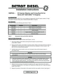
<strong>18SP660Rev2</strong> – <strong>EPA04</strong> <strong>and</strong> <strong>EPA07</strong> <strong>MBE</strong> <strong>4000</strong> <strong>Steel</strong><br />
<strong>Low</strong> Pressure Fuel Line Kits<br />
(P/N: A4600702932 <strong>and</strong><br />
A4600703032)<br />
KIT DESCRIPTION<br />
New service kits (P/N: A4600702932 <strong>and</strong> A4600703032) contain a steel low pressure<br />
fuel line <strong>and</strong> associated parts to replace the former plastic fuel line. In addition to<br />
installing the parts, <strong>EPA04</strong> engines relative to recall 11C2 equipped with a Hengst fuel<br />
filter housing with engine serial numbers from 0460878301 to 0460884090 <strong>and</strong> <strong>EPA07</strong><br />
engines relative to recall 09C2 with a Hengst fuel filter housing with engine serial<br />
numbers from 0460847011 to 0460888753 must have the fuel filter housing wall<br />
thickness inspected.<br />
KIT CONTENTS<br />
The two new service kits contain the parts listed in Table 1:<br />
Part No.<br />
Description<br />
<strong>EPA04</strong> Kit P/N:<br />
A4600702932<br />
(qty.)<br />
<strong>EPA07</strong> Kit P/N:<br />
A4600703032<br />
(qty.)<br />
A4600702832 <strong>Steel</strong> <strong>Low</strong> Pressure Fuel Line 1 1<br />
N915036012101 Banjo Bolt – M16 x 28 2 1<br />
N915047012100 Banjo Bolt – M16 x 46 - 1<br />
N000000001070 Seal Ring 4 5<br />
<strong>18SP660Rev2</strong> Installation Instructions 1 1<br />
Table 1<br />
<strong>EPA04</strong> <strong>and</strong> <strong>EPA07</strong> <strong>MBE</strong> <strong>4000</strong> <strong>Steel</strong> <strong>Low</strong> Pressure Fuel Line Kits<br />
NOTE:<br />
If engine is currently equipped with the steel low pressure fuel line part number<br />
A4600702832, no further action is required.<br />
<strong>18SP660Rev2</strong> Page 1 of 9
REPLACEMENT PROCEDURE<br />
Install the new steel low pressure fuel line as follows.<br />
NOTE:<br />
Certain parts must be retained during the removal process for reuse during the<br />
installation process. These parts will be noted in bolded font in the removal steps below.<br />
REMOVAL<br />
1. Apply the parking brake, chock the wheel, disconnect vehicle battery power, <strong>and</strong><br />
perform any other applicable safety steps.<br />
2. Open the fuel tank fill cap to release pressure in the fuel system. Replace <strong>and</strong><br />
tighten the cap.<br />
3. Loosen the alternator belt.<br />
4. Remove four M10 x 100 bolts that secure the alternator to its mounting bracket.<br />
Save bolts for reuse.<br />
<strong>18SP660Rev2</strong> Page 2 of 9
5. Gently remove the alternator <strong>and</strong> set on frame rail. Be careful not to damage the<br />
alternator or the cables attached to it. See Figure 1.<br />
Figure 1<br />
Alternator Removal<br />
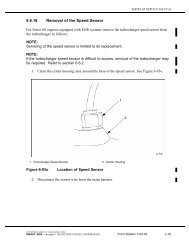
6. Remove two M8 x 40 bolts from the low pressure fuel line clamps. Save bolts<br />
<strong>and</strong> clamps for reuse. See Figure 2.<br />
Figure 2<br />
Fuel Line Clamp Removal<br />
<strong>18SP660Rev2</strong> Page 3 of 9
7. Remove M16 x 28 banjo bolt on plastic low pressure fuel line at front of block<br />
through access hole in alternator mounting bracket. Do NOT remove the spacer<br />
the bolt threads in to. Discard banjo bolt <strong>and</strong> two seal rings. See Figure 3. Torque<br />
spacer to 50 N·m (37 lb·ft) to insure it did not loosen during banjo bolt removal.<br />
NOTE:<br />
In a suitable container, catch any fuel that runs out of the low pressure fuel line or<br />
cylinder block.<br />
Figure 3<br />
Cylinder Block Banjo Bolt Removal<br />
<strong>18SP660Rev2</strong> Page 4 of 9
8. Remove banjo bolt at other end of low pressure fuel line at fuel filter housing.<br />
Discard the banjo bolt <strong>and</strong> seal rings. See Figure 4 (<strong>EPA07</strong> configuration).<br />
NOTE:<br />
In a suitable container, catch any fuel that runs out of the low pressure fuel line or fuel<br />
filter housing.<br />
Figure 4<br />
Fuel Filter Housing Banjo Bolt Removal (<strong>EPA07</strong> Configuration)<br />
9. Remove plastic low pressure fuel line from engine. Discard fuel line. Be careful<br />
not to damage the hydrocarbon doser block fuel supply line<br />
(<strong>EPA07</strong> configuration).<br />
<strong>18SP660Rev2</strong> Page 5 of 9
10. Engines equipped with a Hengst fuel filter housing with an <strong>EPA04</strong> engine relative<br />
to recall 11C2, serial numbers between 0460878301 <strong>and</strong> 0460884090 or <strong>EPA07</strong><br />
engines relative to recall 09C2, serial numbers between 0460847011 <strong>and</strong><br />
0460888753 must have the fuel filter housing wall thickness inspected. Insert tool<br />
J-50161 into the hole in the fuel filter housing where the low pressure fuel line<br />
was removed, until it bottoms out.<br />
NOTE:<br />
On the Hengst housing, the low pressure fuel line bore is marked with a<br />
letter “A” for reference. See Figure 5.<br />
Figure 5<br />
<strong>Low</strong> Pressure Fuel Line Hole<br />
11. Swing the tool arm up from the bottom to avoid interference with fuel lines. See<br />
Figure 6.<br />
a. If the arm DOES NOT go past the end of the fuel filter housing, the<br />
housing has sufficient wall thickness.<br />
b. If the arm DOES go past the end of the fuel filter housing <strong>and</strong> ends up<br />
parallel with the stationary body of the gauge, the housing does not have<br />
sufficient wall thickness <strong>and</strong> MUST be replaced.<br />
NOTE:<br />
Refer to 10 TS-5 for warranty information <strong>and</strong> DDC-SVC-MAN-0026 for<br />
repair information.<br />
<strong>18SP660Rev2</strong> Page 6 of 9
Figure 6<br />
Fuel Filter Housing Thickness Measurement<br />
INSTALLATION<br />
1. Place new steel low pressure fuel line (P/N: A4600702832) into position.<br />
2. Install <strong>and</strong> h<strong>and</strong> tighten new M16 x 28 banjo bolt (P/N: N915036012101) with two<br />
new seal rings (P/N: N000000001070) on new steel low pressure fuel line into<br />
spacer at front of cylinder block through alternator mounting bracket access hole.<br />
3. Install <strong>and</strong> h<strong>and</strong> tighten new M16 banjo bolt at fuel filter housing:<br />
a. For <strong>EPA04</strong> configuration, use M16 x 28 banjo bolt (P/N: N915036012101)<br />
with two new seal rings (P/N: N000000001070).<br />
b. For <strong>EPA07</strong> configuration, use M16 x 46 banjo bolt (P/N: N915047012100)<br />
with three new seal rings (P/N: N000000001070), along with the<br />
hydrocarbon doser block fuel supply line. The new steel low pressure fuel<br />
line will be closest to the fuel filter housing. Do NOT bend either the steel<br />
low pressure fuel line or the hydrocarbon doser block fuel supply line. See<br />
Figure 7 for the correct installation of the lines.<br />
<strong>18SP660Rev2</strong> Page 7 of 9
Figure 7<br />
<strong>Steel</strong> Fuel Line Installation (<strong>EPA07</strong> Configuration)<br />
4. Torque the banjo bolts to 40 N·m (30 lb·ft), starting with the banjo bolt at the front<br />
of the cylinder block.<br />
5. Install fuel line clamps in their original positions. Clamps must go over foam<br />
covered areas of the fuel lines. See Figure 8.<br />
Figure 8<br />
<strong>Steel</strong> Fuel Line Clamp Installation (<strong>EPA07</strong> Configuration)<br />
<strong>18SP660Rev2</strong> Page 8 of 9
6. Torque clamp bolts to 25 N·m (18 lb·ft).<br />
7. Install alternator to its mounting bracket with four M10 x 100 bolts. Torque bolts<br />
to 46 N·m (34 lb·ft).<br />
8. Install <strong>and</strong> tighten alternator belt to correct specifications.<br />
9. Reconnect vehicle battery power.<br />
10. Prime fuel system.<br />
11. Start engine.<br />
12. For <strong>EPA07</strong> engines, use the purge function in DDDL/DDRS 7.0 to purge all the<br />
air from the hydrocarbon doser system.<br />
13. Run engine <strong>and</strong> verify repair.<br />
Specifications are subject to change without notice. Detroit Diesel Corporation is registered to ISO 9001:2001.<br />
Copyright © 2012 Detroit Diesel Corporation. All rights reserved. Detroit Diesel Corporation is a Daimler company.<br />
<strong>18SP660Rev2</strong> 1202 As technical advances continue, specifications will change. Printed in U.S.A.<br />
<strong>18SP660Rev2</strong> Page 9 of 9