ABX8XX-I2C-EVK / ABX8XX-SPI-EVK User's Guide - Abracon
ABX8XX-I2C-EVK / ABX8XX-SPI-EVK User's Guide - Abracon
ABX8XX-I2C-EVK / ABX8XX-SPI-EVK User's Guide - Abracon

Create successful ePaper yourself
Turn your PDF publications into a flip-book with our unique Google optimized e-Paper software.
AB08XX/AB18XX Real Time Clock Family<br />
Evaluation Kit User’s <strong>Guide</strong><br />
<strong>ABX8XX</strong>-<strong>I2C</strong>-<strong>EVK</strong> / <strong>ABX8XX</strong>-<strong>SPI</strong>-<strong>EVK</strong><br />
Pin<br />
Number<br />
Pin Name<br />
Board<br />
Pull-up<br />
Resistor<br />
20 SUCAP_DIS --<br />
21 VTEMP --<br />
22 LED --<br />
23 VSYS -- Test point<br />
24 VPP_CON -- Test point<br />
Description<br />
Super capacitor disconnect signal. This signal can be used to<br />
connect/disconnect the super capacitor from the <strong>ABX8XX</strong> VBAT pin.<br />
Additional component population changes are required to use this<br />
feature.<br />
This is the analog voltage output from the temperature sensor IC on<br />
the board. The temperature sensor IC is not populated on the board<br />
by default.<br />
This pin connects to the debug LED populated on the board through<br />
a 510 ohm resistor.<br />
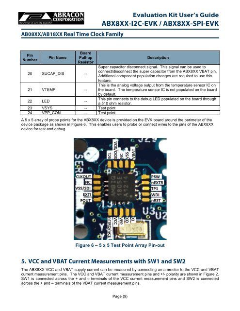
A 5 x 5 array of probe points for the <strong>ABX8XX</strong> device is provided on the <strong>EVK</strong> board around the perimeter of the<br />
device package as shown in Figure 6. This enables users to probe or connect wires to the pins of the <strong>ABX8XX</strong><br />
device for test and debug.<br />
Figure 6 – 5 x 5 Test Point Array Pin-out<br />
5. VCC and VBAT Current Measurements with SW1 and SW2<br />
The <strong>ABX8XX</strong> VCC and VBAT supply current can be measured by connecting an ammeter to the VCC and VBAT<br />
current measurement pins. The VCC and VBAT current measurement pins and +/- polarity are shown in Figure 2.<br />
SW1 is connected across the + and – terminals of the VCC current measurement pins and SW2 is connected<br />
across the + and – terminals of the VBAT current measurement pins.<br />
Page (9)