ABX8XX-I2C-EVK / ABX8XX-SPI-EVK User's Guide - Abracon
ABX8XX-I2C-EVK / ABX8XX-SPI-EVK User's Guide - Abracon
ABX8XX-I2C-EVK / ABX8XX-SPI-EVK User's Guide - Abracon

Create successful ePaper yourself
Turn your PDF publications into a flip-book with our unique Google optimized e-Paper software.
AB08XX/AB18XX Real Time Clock Family<br />
Evaluation Kit User’s <strong>Guide</strong><br />
<strong>ABX8XX</strong>-<strong>I2C</strong>-<strong>EVK</strong> / <strong>ABX8XX</strong>-<strong>SPI</strong>-<strong>EVK</strong><br />
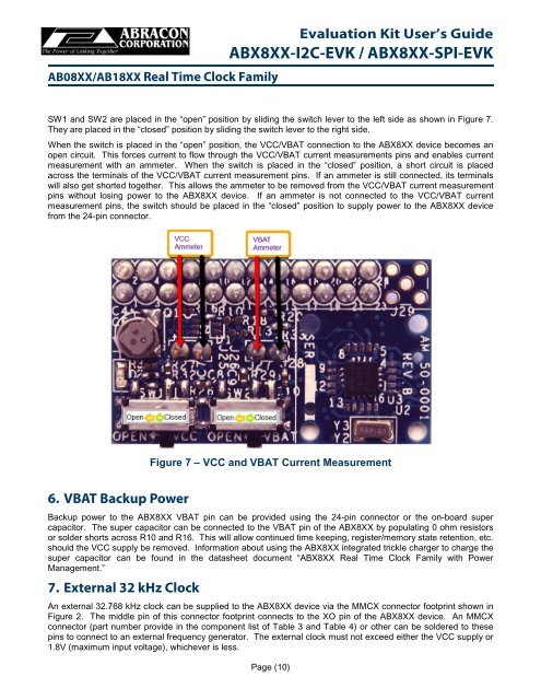
SW1 and SW2 are placed in the “open” position by sliding the switch lever to the left side as shown in Figure 7.<br />
They are placed in the “closed” position by sliding the switch lever to the right side.<br />
When the switch is placed in the “open” position, the VCC/VBAT connection to the <strong>ABX8XX</strong> device becomes an<br />
open circuit. This forces current to flow through the VCC/VBAT current measurements pins and enables current<br />
measurement with an ammeter. When the switch is placed in the “closed” position, a short circuit is placed<br />
across the terminals of the VCC/VBAT current measurement pins. If an ammeter is still connected, its terminals<br />
will also get shorted together. This allows the ammeter to be removed from the VCC/VBAT current measurement<br />
pins without losing power to the <strong>ABX8XX</strong> device. If an ammeter is not connected to the VCC/VBAT current<br />
measurement pins, the switch should be placed in the “closed” position to supply power to the <strong>ABX8XX</strong> device<br />
from the 24-pin connector.<br />
Figure 7 – VCC and VBAT Current Measurement<br />
6. VBAT Backup Power<br />
Backup power to the <strong>ABX8XX</strong> VBAT pin can be provided using the 24-pin connector or the on-board super<br />
capacitor. The super capacitor can be connected to the VBAT pin of the <strong>ABX8XX</strong> by populating 0 ohm resistors<br />
or solder shorts across R10 and R16. This will allow continued time keeping, register/memory state retention, etc.<br />
should the VCC supply be removed. Information about using the <strong>ABX8XX</strong> integrated trickle charger to charge the<br />
super capacitor can be found in the datasheet document “<strong>ABX8XX</strong> Real Time Clock Family with Power<br />
Management.”<br />
7. External 32 kHz Clock<br />
An external 32.768 kHz clock can be supplied to the <strong>ABX8XX</strong> device via the MMCX connector footprint shown in<br />
Figure 2. The middle pin of this connector footprint connects to the XO pin of the <strong>ABX8XX</strong> device. An MMCX<br />
connector (part number provide in the component list of Table 3 and Table 4) or other can be soldered to these<br />
pins to connect to an external frequency generator. The external clock must not exceed either the VCC supply or<br />
1.8V (maximum input voltage), whichever is less.<br />
Page (10)