ABX8XX-I2C-EVK / ABX8XX-SPI-EVK User's Guide - Abracon
ABX8XX-I2C-EVK / ABX8XX-SPI-EVK User's Guide - Abracon
ABX8XX-I2C-EVK / ABX8XX-SPI-EVK User's Guide - Abracon

Create successful ePaper yourself
Turn your PDF publications into a flip-book with our unique Google optimized e-Paper software.
AB08XX/AB18XX Real Time Clock Family<br />
Evaluation Kit User’s <strong>Guide</strong><br />
<strong>ABX8XX</strong>-<strong>I2C</strong>-<strong>EVK</strong> / <strong>ABX8XX</strong>-<strong>SPI</strong>-<strong>EVK</strong><br />
Board Component<br />
LED<br />
SW1<br />
SW2<br />
32.768kHz crystal<br />
AB180X / AB181X<br />
MMCX Footprint<br />
Description<br />
A separate pin on the 24-pin socket connector connects to the LED. This<br />
LED can be controlled by an MCU GPIO pin or can be connected directly<br />
to the VCC or VBAT supply to indicate one of the supplies has power<br />
applied.<br />
This switch is connected in parallel with the VCC current measurement<br />
pins. It is used to short across the pins and connect the external VCC<br />
supply to the <strong>ABX8XX</strong> when not measuring current with the picoammeter.<br />
This switch is connected in parallel with the VBAT current measurement<br />
pins. It is used to short across the pins and connect the external VBAT<br />
supply to the <strong>ABX8XX</strong> when not measuring current with the picoammeter.<br />
The crystal is connected to the XI and XO pins of the <strong>ABX8XX</strong> device<br />
I 2 C (AB180X) or <strong>SPI</strong> (AB181X) real time clock device.<br />
This can be used for providing an external clock input.<br />
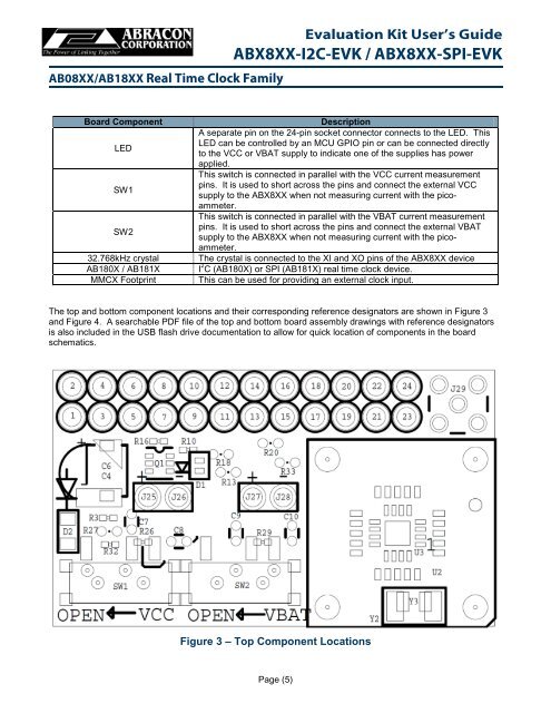
The top and bottom component locations and their corresponding reference designators are shown in Figure 3<br />
and Figure 4. A searchable PDF file of the top and bottom board assembly drawings with reference designators<br />
is also included in the USB flash drive documentation to allow for quick location of components in the board<br />
schematics.<br />
Figure 3 – Top Component Locations<br />
Page (5)