H1900 replacement backup battery guide - iPAQ Repair and Parts
H1900 replacement backup battery guide - iPAQ Repair and Parts
H1900 replacement backup battery guide - iPAQ Repair and Parts

Create successful ePaper yourself
Turn your PDF publications into a flip-book with our unique Google optimized e-Paper software.
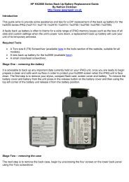
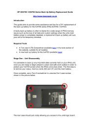
Introduction<br />
<strong>H1900</strong> Replacement Backup Battery Guide<br />
By Nathan Dickman<br />
http://www.ipaqrepair.co.uk<br />
This is a step by step <strong>guide</strong> to replacing your back up <strong>battery</strong> for the <strong>H1900</strong> series<br />
<strong>iPAQ</strong>. Please be aware this procedure involves opening the back of the unit, thus<br />
voiding your HP warranty.<br />
Required Tools<br />
A Torx 6 Screwdriver (available in the tools section of the website)<br />
A 1900 series <strong>backup</strong> <strong>battery</strong> (available in the batteries section under the 1900 Series)<br />
A small jewellers cross head screwdriver<br />
Optional Tools<br />
A flat headed screwdriver (for levering away the back case)<br />
Now you have the <strong>backup</strong> <strong>battery</strong>, Torx <strong>and</strong> crosshead screwdrivers required to<br />
complete this <strong>replacement</strong>, begin by following the simple 11 steps.<br />
Step One<br />
It is advisable before undertaking this procedure to back up any important data held on<br />
your <strong>iPAQ</strong>. After doing so you are ready to begin. The SD card / SD filler card, stylus<br />
<strong>and</strong> <strong>battery</strong> all have to be removed. To remove the <strong>battery</strong> use the <strong>battery</strong> cover<br />
release button on the left of the <strong>iPAQ</strong> (circled), bring the button up to release the<br />
<strong>battery</strong> cover, <strong>and</strong> also remove the <strong>battery</strong> – which should simply lift out.
Step Two<br />
Next, unscrew the five screws holding the back case together, there are two screws at<br />
the top of the unit, two at the bottom <strong>and</strong> the fifth is located to the right of the <strong>battery</strong><br />
area, beneath the warranty sticker.<br />
Step Three<br />
Once the screws have been removed you will need to pop the clips that hold the front<br />
<strong>and</strong> back cases together. Starting in the top right, use your screwdriver to prise the top<br />
right section off, <strong>and</strong> moving downwards use your nails or screwdriver to continue<br />
popping the clips away from the case until the back case is easily removed.
Step Four<br />
You now have access to the inside of your unit. Using a small cross head screwdriver<br />
remove the two black screws (see circled) in the top left, <strong>and</strong> bottom right which hold<br />
the main board to the body.<br />
Step Five<br />
With these screws removed you now need to detach any components connected to the<br />
mainboard, detach the screen cable (see image one) which should simply lift up <strong>and</strong><br />
away from the connector, then detach the action button cable by bringing down the<br />
brown clips, <strong>and</strong> then pulling the cable away from the connector (see image two)
Step Six<br />
With these components detached you are ready for the next step. Without removing<br />
the board fully you should be able to detach the old <strong>backup</strong> <strong>battery</strong> connector located<br />
at the reverse of the main board, which is located at the bottom of the main board (see<br />
image below). In order to access this you are required to lift away the main board. This<br />
is done by pulling the board slightly downwards, <strong>and</strong> then away. Once the board has<br />
been lifted up enough you will be able to detach this lead by pulling the lead head<br />
away from the connector.<br />
Step Seven<br />
In order to have sufficient room to complete this <strong>replacement</strong> you should now put the<br />
main board aside for now. You can now replace the <strong>backup</strong> <strong>battery</strong>. The <strong>battery</strong> leads<br />
should be held under a black lead clip, to release the lead carefully pull the leads in the<br />
direction indicated below, these leads may be held close to the front plate so it<br />
advisable to push them against the front plate as you pull away. Once the leads are<br />
free you can remove the old <strong>backup</strong> <strong>battery</strong> by pulling it off its adhesive spot.
Step Eight<br />
Attach your new <strong>battery</strong> in the same position using the adhesive spot. Carefully push<br />
the leads underneath the black lead clip (this may be fiddly, it may be advisable to use<br />
your stylus or other tool to carefully tease it into position beneath the clip). This clip<br />
works to stop the cables getting caught <strong>and</strong> damaged in between the mainboard or<br />
case.<br />
Step Nine<br />
You are now required to reattach the <strong>backup</strong> <strong>battery</strong> cable into the connector, which<br />
should easily clip back in to the connector located on the reverse of the mainboard<br />
(See image below). With this now attached you are now ready to reassemble your unit.
Step Ten<br />
Though a simple step you should take some time to be sure that all components are<br />
reattached <strong>and</strong> in place. Reattach the main board by leading it into position by putting<br />
the top section into position first – making sure that the black rubber-bound speaker is<br />
in position <strong>and</strong> that any clips <strong>and</strong> screw holes are aligned. Once you are sure this is<br />
safely aligned reattach the two cables – the screen cable (see image, reference<br />
number one) <strong>and</strong> action button cable (see image, reference number two) are both<br />
reattached. Once the board is perfectly aligned, with all components connected simply<br />
put back in the two black screws (for reference use Step Four)<br />
Step Eleven<br />
With all of this connected, simply pop the case back on <strong>and</strong> put in the five screws that<br />
hold the back case on, affix your <strong>battery</strong>, <strong>battery</strong> cover <strong>and</strong> stylus. Et voila, you have<br />
successfully replaced your <strong>backup</strong> <strong>battery</strong>! With this completed charge your <strong>iPAQ</strong> for<br />
24 hours to allow both the new <strong>backup</strong> <strong>battery</strong> <strong>and</strong> main <strong>battery</strong> to recalibrate. After<br />
this your unit is ready to be used.<br />
The text <strong>and</strong> images are © Nathan Dickman, if you wish to distribute or use this<br />
document in any way please contact me via the website located at:<br />
http://www.ipaqrepair.co.uk/contact_us.php<br />
Revision History<br />
Version 1.2 13:58 PM 30/12/06