MR-EF (EARTH FAULT Protection Relay ... - PBSI Group Ltd
MR-EF (EARTH FAULT Protection Relay ... - PBSI Group Ltd
MR-EF (EARTH FAULT Protection Relay ... - PBSI Group Ltd

Create successful ePaper yourself
Turn your PDF publications into a flip-book with our unique Google optimized e-Paper software.
<strong>MR</strong>-<strong>EF</strong> Technical Manual<br />
<strong>MR</strong>-<strong>EF</strong><br />
(<strong>EARTH</strong> <strong>FAULT</strong> <strong>Protection</strong> <strong>Relay</strong>)<br />
Technical Manual<br />
P&B Engineering (UK) <strong>Ltd</strong><br />
Belle Vue Works<br />
Boundary Street<br />
Manchester<br />
M12 5NG<br />
t +44 (0)161 230 636 f +44 (0)161 230 6464 w www.pbeng.co.uk e mail@pbeng.co.uk<br />
P & B Engineering Page 1 Issue 1. April 07
<strong>MR</strong>-<strong>EF</strong> Technical Manual<br />
1. GENERAL DESCRIPTION .......................................................................................5<br />
1.1 PROTECTION FUNCTIONS 1.2 DISPLAYABLE DATA........................................5<br />
1.3 DISPLAYABLE <strong>MR</strong>-<strong>EF</strong> STATUS 1.4 CONTROL OUTPUT RELAYS........................5<br />
1.5 CONTROL INPUTS. ..............................................................................................5<br />
2. TECHNICAL SPECIFICATION ................................................................................6<br />
Power Supply ..................................................................................................................................... 6<br />
Measurement ..................................................................................................................................... 6<br />
<strong>Protection</strong> Functions .......................................................................................................................... 6<br />
<strong>Relay</strong> Contacts Ratings ...................................................................................................................... 6<br />
3. ENVIRONMENTAL TESTS. .....................................................................................7<br />
4. <strong>MR</strong>-<strong>EF</strong> TERMINATIONS.........................................................................................7<br />
5. <strong>MR</strong>-<strong>EF</strong> ANALOGUE INPUTS. ..................................................................................7<br />
5.1. Power Supply Live....................................................................................................................... 7<br />
5.2 Conventional Current Transformers ............................................................................................ 7<br />
6. <strong>MR</strong>-<strong>EF</strong> SERIAL PORT .............................................................................................7<br />
6.1. RS485.......................................................................................................................................... 7<br />
6.2. Profibus - Optional ..................................................................................................................... 7<br />
6.3. RS232.......................................................................................................................................... 8<br />
7.0 PROTECTION FUNCTIONS. .................................................................................8<br />
7.1 <strong>MR</strong>-<strong>EF</strong> SETTINGS ................................................................................................8<br />
7.2 <strong>EF</strong> CT Primary............................................................................................................................... 8<br />
7.3. PROTECTION SETTINGS. ...................................................................................8<br />
7.3.1 Earth Fault................................................................................................................................. 9<br />
7.3.2 Serial Timeout. .......................................................................................................................... 9<br />
7.3.3 Internal Error ............................................................................................................................ 9<br />
7.3.4 Alarm......................................................................................................................................... 9<br />
P & B Engineering Page 2 Issue 1. April 07
<strong>MR</strong>-<strong>EF</strong> Technical Manual<br />
7.3.5 Trip. ........................................................................................................................................... 9<br />
7.3.6 Reset. ........................................................................................................................................ 9<br />
7.3.7 Auto Reset................................................................................................................................. 9<br />
7.3.8 Panel-Reset............................................................................................................................... 9<br />
7.3.9 Blocking Input......................................................................................................................... 10<br />
7.3.10 Remote Reset........................................................................................................................ 10<br />
8. SYSTEM SETTINGS..............................................................................................11<br />
8.1 Password.................................................................................................................................... 11<br />
8.2 Change Password....................................................................................................................... 11<br />
8.3 LCD Contrast and LCD Backlight. ............................................................................................... 11<br />
8.4 Set Default Page / Default Return Time. ................................................................................... 11<br />
8.5 Default Return Time................................................................................................................... 11<br />
8.6 Time Sync Delay. (Only for use with Chronovision) .................................................................. 11<br />
8.7 Software Version........................................................................................................................ 12<br />
8.8 Unit ID. / Unit Type.................................................................................................................... 12<br />
8.9 Software Activation Keys ........................................................................................................... 12<br />
8.10 Time and Date. ......................................................................................................................... 12<br />
8.11 Chronovision ............................................................................................................................ 12<br />
8.12 Screen Saver ............................................................................................................................ 12<br />
8.13 Screen Saver Time ................................................................................................................... 12<br />
9. SERIAL SETTINGS...............................................................................................12<br />
9.1 Serial Enabled / Disabled........................................................................................................... 12<br />
9.2 Feeder Number........................................................................................................................... 12<br />
9.3 RS485 Baud Rate. ...................................................................................................................... 12<br />
9.4 RS232 Baud Rate. ...................................................................................................................... 12<br />
9.5 Serial Delay. ............................................................................................................................... 13<br />
9.7 Fast Scan 1 to 3.......................................................................................................................... 13<br />
9.8 Max Scan Time. .......................................................................................................................... 13<br />
9.9 Protocol. (RS232 & RS485)........................................................................................................ 13<br />
9.10 Parity. (RS232 & RS485).......................................................................................................... 13<br />
P & B Engineering - 3 - Issue 1. April 07
<strong>MR</strong>-<strong>EF</strong> Technical Manual<br />
9.11 Serial Timeout <strong>Protection</strong>. ....................................................................................................... 13<br />
10. <strong>MR</strong>-<strong>EF</strong> FACEPLATE FUNCTIONS. .......................................................................14<br />
10.1. LED Status............................................................................................................................... 14<br />
12. MENU TREE STRUCTURE...................................................................................15<br />
12. GRAPHICAL DISPLAY........................................................................................16<br />
12.1. Menu Screens.......................................................................................................................... 16<br />
12.2. Display Scroll........................................................................................................................... 17<br />
12.3. Menu. ...................................................................................................................................... 17<br />
12.4. <strong>MR</strong>-<strong>EF</strong> Settings........................................................................................................................ 18<br />
12.5. Serial Settings. ....................................................................................................................... 18<br />
12.6. I / O Settings. ....................................................................................................................... 19<br />
12.7.1. PROGRAMMABLE OUTPUT. .........................................................................20<br />
12.7.2 Not Used. ................................................................................................................................... 20<br />
12.7.2 Alarm. ........................................................................................................................................ 20<br />
12.7.3 Alarm Fail-Safe............................................................................................................................ 20<br />
12.7.4 Trip. ........................................................................................................................................... 20<br />
12.7.5 Trip Fail Safe................................................................................................................................ 20<br />
12.7.6 Healthy....................................................................................................................................... 20<br />
12.7.7 Healthy Fail Safe ......................................................................................................................... 20<br />
12.7.8 Internal Fail ................................................................................................................................ 20<br />
12.8. System Settings. .................................................................................................................... 21<br />
12.9. Calibration Menu..................................................................................................................... 21<br />
12.10. Smart Card Settings. (OPTIONAL) ........................................................................................ 21<br />
13.1 IEC OVERCURRENT INVERSE-TIME CHARACTERISTIC EQUATIONS .............22<br />
14.1 VISION INSTALLATION DIAGRAM .................................................................24<br />
14.2. TERMINATION DETAILS SUMMARY .............................................................25<br />
15. FAST SCAN NUMBERS .......................................................................................25<br />
16. SETTING PAGES SUMMARY .............................................................................26<br />
17. ORDER FORM ....................................................................................................27<br />
P & B Engineering - 4 - Issue 1. April 07
<strong>MR</strong>-<strong>EF</strong> Technical Manual<br />
1. GENERAL DESCRIPTION<br />
P+B Engineering, design and manufacture a range of Drawout <strong>Protection</strong> <strong>Relay</strong>s and Intelligent <strong>Protection</strong> and<br />
Control Systems. These Microprocessor based range of relays are mounted in 50, 100, 150 and 200mm wide<br />
Drawout cases. In general terms, Auxiliary and Tripping relays are supplied in 50mm cases. The majority of<br />
<strong>MR</strong>-<strong>EF</strong>, Feeder, Transformer, Generator and Motor protection relays are fitted into 100mm wide cases and the<br />
more complex Multifunction relays command wider 150 and 200mm cases.<br />
The Vision range of <strong>Protection</strong> <strong>Relay</strong>s and Controllers, are sub-divided into two categories:<br />
1. <strong>MR</strong> Range – Cost effective General <strong>Protection</strong> Drawout <strong>Relay</strong>s with a 2 line LCD display.<br />
2. Vision Drawout – Multifunction <strong>Protection</strong> and Control devices with a large, fully graphical LCD display.<br />
<strong>MR</strong>-<strong>EF</strong> This manual describes the <strong>MR</strong>-<strong>EF</strong> Drawout cased<br />
Microprocessor based Earth/Ground Fault <strong>Relay</strong><br />
1.1 <strong>Protection</strong> Functions 1.2 Displayable Data<br />
• Earth Fault (IEC Curves)<br />
• Serial Timeout protection<br />
• Internal Error <strong>Protection</strong><br />
• Earth Fault Current<br />
• Trip Status<br />
• Alarm Status<br />
• Digital I/O Status<br />
• Active Fault Status<br />
1.3 Displayable <strong>MR</strong>-<strong>EF</strong> Status 1.4 Control Output <strong>Relay</strong>s<br />
• Healthy / Trip / Alarm<br />
• Alarm Description<br />
• Trip Description<br />
• 1 <strong>Relay</strong> Output Fixed for<br />
trip Pulse<br />
• 3 Programmable Output<br />
Trip <strong>Relay</strong>s<br />
1.5 Control Inputs.<br />
• 2 Programmable Inputs<br />
o<br />
P & B Engineering - 5 - Issue 1. April 07
<strong>MR</strong>-<strong>EF</strong> Technical Manual<br />
2. Technical Specification<br />
Power Supply<br />
Auxiliary Power Supply & Low Voltage Power Supply<br />
AC Nominal<br />
Frequency<br />
Range 80 – 265V AC / DC<br />
Range 24V AC / 24-48V Dc (Low Voltage Power Supply Optional Extra)<br />
50 OR 60 Hz<br />
Maximum Power Consumption<br />
10VA, 15VA Nominal<br />
Measurement<br />
Earth Fault Current Measurement<br />
Method<br />
Range<br />
Display Accuracy<br />
Pick Up accuracy<br />
CT Burden<br />
True RMS, Sample time
<strong>MR</strong>-<strong>EF</strong> Technical Manual<br />
3. Environmental Tests.<br />
P+B <strong>Protection</strong> <strong>Relay</strong>s and Controllers are all type tested over a range of climatic, mechanical, electrical and<br />
electromagnetic compatibility IEC tests. Please refer to Type Test information to be found on<br />
www.pbeng.co.uk<br />
4. <strong>MR</strong>-<strong>EF</strong> Terminations.<br />
External connections are made using crimp or screw terminals to the MIDOS connection block. This then allows<br />
pre-wiring to be carried out prior to fitting into the switchgear. These are suitable for accepting 2.5 sq. mm<br />
wire.<br />
See SECTION 14.2 for terminal assignment.<br />
5. <strong>MR</strong>-<strong>EF</strong> Analogue Inputs.<br />
5.1. Power Supply Live<br />
The <strong>MR</strong>-<strong>EF</strong> requires an AC or DC Voltage to supply the unit. The digital inputs are connected to this supply too.<br />
The <strong>MR</strong>-<strong>EF</strong> can also be fitted with a Low Voltage Power Supply (PSU) and / or Low Voltage digital inputs.<br />
5.2 Conventional Current Transformers<br />
Normally, the <strong>MR</strong>-<strong>EF</strong> has provision to allow connection of standard 1 amp or 5 amp secondary current<br />
transformer.<br />
6. <strong>MR</strong>-<strong>EF</strong> Serial Port<br />
6.1. RS485<br />
The Serial Port supplied with <strong>MR</strong>-<strong>EF</strong> as standard utilises a half duplex RS485 protocol allowing up to 32 units to<br />
be daisy-chained together, or to be multi-drop connected with a single shielded twisted pair cable.<br />
The <strong>MR</strong>-<strong>EF</strong> in addition to its very comprehensive protection and control features has been equipped with a very<br />
powerful data communications system. It provides high-speed data acquisition to supervisory computers to<br />
form a complete protection monitoring.<br />
Each <strong>MR</strong>-<strong>EF</strong> can be connected to an isolated data highway using RS485 communications. Up to 32 units can be<br />
connected to each data highway. The host system can interrogate the unit to monitor status, historical data and<br />
fault data as well as control functions such as reset fault / alarm conditions.<br />
The <strong>MR</strong>-<strong>EF</strong> is available with P&B network gold (P&B protocol) installed for use with the Xcell Data Concentrator<br />
for fully Integrated <strong>Protection</strong>, Control & Monitoring Systems with full dual redundancy or with a Slave<br />
implementation of Modbus RTU protocol for small systems and direct Modbus access to devices where data<br />
concentration is not required.<br />
6.2. Profibus - Optional<br />
Please contact P&B Engineering for further details of this optional protocol.<br />
P & B Engineering - 7 - Issue 1. April 07
<strong>MR</strong>-<strong>EF</strong> Technical Manual<br />
6.3. RS232<br />
This RS232 port allows access to historical and dynamic data without disturbing the rear RS485 network.<br />
Full details of the protocols, device mapping, gsd files and other support documents are available on request.<br />
Information on the Xcell Data Concentrator is contained in the P&B Integrated <strong>Protection</strong> & Control System<br />
Integrators Manual, available on request.<br />
7.0 <strong>Protection</strong> Functions.<br />
7.1 <strong>MR</strong>-<strong>EF</strong> Settings<br />
7.2 <strong>EF</strong> CT Primary<br />
This setting allows the user to program the primary current rating of the protection class current transformers<br />
on the supply phases. It is assumed that all phase current transformers are of the same rating.<br />
7.3. <strong>Protection</strong> Settings.<br />
The protection functions are configurable independently of the others settings.<br />
The <strong>MR</strong>-<strong>EF</strong> provides the following settings to choose from:<br />
# Selectable Option<br />
Protective Function<br />
ANSI No.<br />
50/51N Earth Fault<br />
Trip<br />
#<br />
Alarm<br />
Alarm &<br />
Trip<br />
Available<br />
Action<br />
# #<br />
Auto<br />
Panel<br />
# # #<br />
Serial<br />
Available<br />
Reset<br />
#<br />
Remote<br />
#<br />
Blockable<br />
#<br />
Variable<br />
Range<br />
Step<br />
Trip Level 1% - 1500% 1%<br />
Trip Time (D<strong>EF</strong>T ONLY) 50mS - 60S 0.01s<br />
94 Serial Timeout # # # # # # # # # Timeout In 1-120s 1s<br />
94 Profibus DP Fault ■ # # # # # # # # # Trip Time 1-60s 1s<br />
94 Internal Error # # # # # # # # #<br />
■ Only<br />
Trip<br />
available<br />
Level.rip<br />
on PROFIBUS<br />
time is set<br />
model<br />
to determine<br />
only<br />
how long an earth fault condition can persist before the taken.<br />
P & B Engineering - 8 - Issue 1. April 07
<strong>MR</strong>-<strong>EF</strong> Technical Manual<br />
7.3.1 Earth Fault<br />
There two independent stages of Earth Fault <strong>Protection</strong>.<br />
● Low Set Earth Fault Overcurrent<br />
● High Set Earth Fault Overcurrent (Definite Time Characteristic Only)<br />
The <strong>MR</strong>-<strong>EF</strong> may be configured to trip, alarm and/or indicate as a result of an Earth Fault condition.<br />
The following options are available for the Earth Low Set protection characteristic. Normal Inverse (NINV) Very<br />
Inverse (VINV), Extremely Inverse (EINV) or Definite Time (DT). Refer to section 13 for further details on<br />
these characteristics.<br />
7.3.2 Serial Timeout.<br />
For a set period of inactivity on the rear or front communication port the unit can be configured to take some<br />
action in the event.<br />
It is worth noting that the <strong>MR</strong>-<strong>EF</strong> device is slave to any host system, the unit will not send information via the<br />
serial port unless it has been requested by a master device.<br />
7.3.3 Internal Error<br />
The <strong>MR</strong>-<strong>EF</strong> incorporates an internal software and hardware watchdog feature to monitor the integrity of both<br />
on board hardware and software systems. This feature may be configured to indicate as a result of any<br />
registered problems. If a problem with the hardware or software is located during the error check routines the<br />
<strong>MR</strong>-<strong>EF</strong> will generate an error.<br />
7.3.4 Alarm.<br />
An Alarm is considered as a high level function. If the function activates it cause the <strong>MR</strong>-<strong>EF</strong> to enter an alarm<br />
state; the fault will be displayed on the screen and the right hand LED will turn ORANGE.<br />
If an output relay is set as Alarm it will change state with the fault.<br />
7.3.5 Trip.<br />
A Trip is considered as a high level function. If the function activates it will cause the <strong>MR</strong>-<strong>EF</strong> to enter a trip<br />
state; the fault will be on the screen and the right hand LED will turn RED.<br />
7.3.6 Reset.<br />
The configuration of the reset allows that particular function to be cleared or reset to a healthy condition<br />
providing the condition that caused the fault, alarm or inhibit has been removed.<br />
7.3.7 Auto Reset.<br />
This option, when enabled, automatically resets the Fault when the situation that caused the trip has been<br />
removed.<br />
7.3.8 Panel-Reset.<br />
This option, when Enabled, allows a reset of a fault to be carried out from the front panel of the relay. A reset<br />
button will be displayed on the screen just above the top right button. This will only occur if the fault has been<br />
removed and the <strong>MR</strong>-<strong>EF</strong> is enabled for a panel reset.<br />
P & B Engineering - 9 - Issue 1. April 07
<strong>MR</strong>-<strong>EF</strong> Technical Manual<br />
7.3.9 Blocking Input.<br />
A digital input configured as a “Blocking input” will provide the facility to block any <strong>MR</strong>-<strong>EF</strong> protection function<br />
configured to be “Blockable”. Most of the <strong>MR</strong>-<strong>EF</strong> protection features may have blocking logic assigned. In the<br />
event this digital input changes to a blocking status then all those protection features configured as “Blockable”<br />
will be disabled for the duration of time the blocking input is energised. This feature may be beneficial in<br />
blocking the likes of Undervoltage protection during the starting of large machines connected to the<br />
feeder/transformer being protected.<br />
7.3.10 Remote Reset<br />
Allows remote reset of a protection Trip/alarm on energising of Digital Input. Needs to be configured in<br />
protection settings. Reset = Remote ‘R’<br />
P & B Engineering - 10 - Issue 1. April 07
<strong>MR</strong>-<strong>EF</strong> Technical Manual<br />
8. System Settings.<br />
8.1 Password.<br />
If the password is set to enabled the default password (6363) may be used to change setting and reset<br />
statistical data. If the password has been changed to something else the new password must be used.<br />
Engineer Password – This is generally only used during commissioning/setup of the relay. The option allows<br />
a global password to be used to access the relay’s data and settings menus. When ‘Engineer Password’ is<br />
enabled the following passwords will work for all menus:-<br />
ABAAA, PBACS, xxxxx (User Set Password, Factory Default at P&B is 6363)<br />
When ‘engineer Password’ is disabled only the User Set Password will work. Please note if this user set<br />
password is lost, no other password will override it. The only way to retrieve a lost password is to read back<br />
through the comms or default the relay at power up, back to the factory defaults.<br />
8.2 Change Password.<br />
The <strong>MR</strong>-<strong>EF</strong> default password is '6363'. It is recommended for security purposes this password can be changed.<br />
The password may be up to 6 characters long and alphanumeric if desired.<br />
If the User Password is lost the only options are to either Read the information via the serial Link or execute a<br />
Configuration Reset on the relay to restore all of the factory defaults.<br />
8.3 LCD Contrast and LCD Backlight.<br />
These functions allow the user to change the display contrast and backlight.<br />
Contrast<br />
Y 30 N<br />
Data = 000030<br />
Save Next<br />
Selecting ‘Y’ displays the input screen<br />
Light<br />
Dark<br />
For Contrast 0 128<br />
Maximum<br />
Minimum<br />
For Backlight 0 156<br />
8.4 Set Default Page / Default Return Time.<br />
Any of the display scroll data pages can be nominated as the default page and returned to after a set period of<br />
key press inactivity.<br />
To set the page; select the required one using the display scroll button, then enter the system settings and<br />
select ‘set default page’.<br />
8.5 Default Return Time.<br />
If the <strong>MR</strong>-<strong>EF</strong> is not being accessed using the buttons on the front of the relay after a predetermined time the<br />
relay will default to the Pre-set Page. In this setting you can control that feature. You are able to switch off the<br />
return feature or specify a time for the delay before the return to the Pre-set Page.<br />
8.6 Time Sync Delay. (Only for use with Chronovision)<br />
Chronovision is a GPS based device which connects on the RS485 network and synchronises the time and date<br />
of each connected unit. This delay prevents immediate updating of the RTC.<br />
P & B Engineering - 11 - Issue 1. April 07
<strong>MR</strong>-<strong>EF</strong> Technical Manual<br />
8.7 Software Version.<br />
Displays the operating firmware loaded on to the unit. This should be noted along with the serial number when<br />
corresponding about this equipment<br />
8.8 Unit ID. / Unit Type.<br />
Displays the Serial number and device type.<br />
8.9 Software Activation Keys<br />
In order for some functions to operate a unique activation code is required to access hidden menu screens.<br />
8.10 Time and Date.<br />
These functions allow the user to set the date and the time on the relay.<br />
8.11 Chronovision<br />
When enabled allows the real time clock to be updated via the broadcast GPS sync signal from Chronovision.<br />
8.12 Screen Saver<br />
To help extend the life of the LCD we can power the display down if the application suits. The screen will power<br />
down after the set time from the last key press. The <strong>MR</strong>-<strong>EF</strong> will still operate and can be remotely controlled via<br />
digital inputs or the serial interface. On any key press or active fault the display will re-activate.<br />
8.13 Screen Saver Time<br />
Sets period of inactivity before activating screen saver function.<br />
9. Serial Settings.<br />
9.1 Serial Enabled / Disabled.<br />
This setting allows the user to enable the <strong>MR</strong>-<strong>EF</strong> serial communications port. This setting must be set to<br />
‘Enable’ if communication with the relay through any serial link is required.<br />
9.2 Feeder Number.<br />
This setting range 1 to 32 (125 Profibus), with a default setting of 1, identifies the <strong>MR</strong>-<strong>EF</strong> unit to the Xcell unit<br />
(or any Master device connected to the Data highway) to which the RS485 or Profibus port is connected. When<br />
updating firmware the auto program mode requires the feeder number to be 1.<br />
9.3 RS485 Baud Rate.<br />
This setting allows the user to configure the appropriate communications baud rate such that the <strong>MR</strong>-<strong>EF</strong> can<br />
communicate correctly on the Data Highway to which it is connected.<br />
9.4 RS232 Baud Rate.<br />
This setting allows the user to configure the baud rate for the front mounted RS232 port.<br />
P & B Engineering - 12 - Issue 1. April 07
<strong>MR</strong>-<strong>EF</strong> Technical Manual<br />
9.5 Serial Delay.<br />
The <strong>MR</strong>-<strong>EF</strong> may be configured to respond to a request for information from the serial port instantly or after a<br />
designated delay.<br />
A communications delay may be beneficial to ensure the Master device on the Data Highway receives all<br />
information sent back by the <strong>MR</strong>-<strong>EF</strong> without enduring data collisions on the network.<br />
9.7 Fast Scan 1 to 3.<br />
Each FastScan number can be programmed to export important data when requested. This number references<br />
an internal address in <strong>MR</strong>-<strong>EF</strong> and allows configurable data mapping between units. Typical data could be<br />
Average Phase Current, Voltage and so on. A table of the FastScan reference numbers can be found in<br />
SECTION 15.<br />
9.8 Max Scan Time.<br />
This setting need only be used in order to limit the amount of data traffic on a RS485 network. Dynamic data<br />
can change rapidly, this setting allows the <strong>MR</strong>-<strong>EF</strong> to limit the number of updates it makes to its Fast Scan<br />
values.<br />
9.9 Protocol. (RS232 & RS485)<br />
The RS232/RS485 serial communications ports, may be configured to operate using a slave implementation of<br />
Modbus RTU® or P&B Engineering’s own protocol “P&B Standard” designed to remove some of the speed<br />
issues associated with a function based protocol like Modbus.<br />
9.10 Parity. (RS232 & RS485)<br />
This setting allows the user to set the parity to match that of the host system on the serial link. The options are<br />
“Odd”, “Even” and “None”. Not required if Profibus.<br />
9.11 Serial Timeout <strong>Protection</strong>.<br />
DETAILED IN SECTION 7.3<br />
P & B Engineering - 13 - Issue 1. April 07
<strong>MR</strong>-<strong>EF</strong> Technical Manual<br />
10. <strong>MR</strong>-<strong>EF</strong> Faceplate Functions.<br />
The <strong>MR</strong>-<strong>EF</strong> Faceplate has been designed to provide display and access to all the required information an<br />
operator may require.<br />
This is achieved by using 2 tri-colour LED’s, a LCD display and 4 software driven function keys.<br />
This eliminates the need for additional indication devices on the front of the feeder panel such as Lamps,<br />
Ammeter, Voltmeter, Hours Run Indicator, Operations Counter, etc. which helps reduce the cost of the<br />
switchgear panel and gives improved reliability by the reduction of separate components.<br />
Two line LCD Display<br />
Selector button<br />
for left hand<br />
menu options<br />
RS232 Front<br />
Connection<br />
Selector button for<br />
right hand menu<br />
options<br />
Right Indicator LED<br />
Left Indicator<br />
LED<br />
Up/Down Scroll keys.<br />
For scrolling through<br />
menus or increasing/<br />
decreasing values<br />
The following section details the function of the Front plate devices.<br />
10.1. LED Status.<br />
The LED's on the front of the <strong>MR</strong>-<strong>EF</strong> operates as follows:<br />
LED Colour<br />
Left LED<br />
[<strong>MR</strong>-<strong>EF</strong> Status]<br />
Right LED<br />
[Fault Status]<br />
Green Healthy Healthy<br />
Yellow Inhibit Alarm<br />
Red Internal Fault Fault<br />
P & B Engineering - 14 - Issue 1. April 07
<strong>MR</strong>-<strong>EF</strong> Technical Manual<br />
12. Menu Tree Structure.<br />
INITIAL MENU<br />
DISPLAY SCROLL<br />
Earth Fault Current, Alarm Status, Trip Status, Digital<br />
I/P1 Status, Digital I/P2 Status, Profibus Status (if<br />
option fitted)<br />
MENU<br />
Trip Cause 1 – 32 events<br />
Time/Date<br />
TRIP<br />
HISTORY<br />
Trip Cause 1 – 32 events<br />
Time/Date<br />
ALARM<br />
HISTORY<br />
Alarm<br />
Trip information<br />
Time & Date<br />
LAST<br />
<strong>FAULT</strong><br />
No of Trips<br />
Acc. Trip Current<br />
STATS<br />
INFO<br />
<strong>EF</strong> CT Primary<br />
FEEDER<br />
SETTINGS<br />
Password<br />
Engineer Password<br />
Change Password<br />
Contrast/Backlight Set<br />
Set Default Page<br />
Default Return Time<br />
Time Sync Delay<br />
S/W Ver & Serial No<br />
Enable Smart Card<br />
Time & Date<br />
Chronovision<br />
Screen Saver & Time<br />
SYSTEM SETTINGS<br />
Io Low Gain<br />
Io Low Offset<br />
Io High gain<br />
Io High Offset<br />
Auto I Cal<br />
Reset Cal<br />
Offset Cal<br />
Digital Inputs<br />
Output <strong>Relay</strong> Tests<br />
Noise Check<br />
CALIBRATION<br />
MENU<br />
PROTECT<br />
SETTINGS<br />
<strong>EF</strong>> Action Trip<br />
<strong>EF</strong>> Reset Panel<br />
<strong>EF</strong>> Trip Level<br />
<strong>EF</strong>> Trip Time<br />
<strong>EF</strong>> Characteristic<br />
<strong>EF</strong>> Times Multiplier<br />
<strong>EF</strong>>> Action Trip<br />
<strong>EF</strong>>> Reset Panel<br />
<strong>EF</strong>>> Trip Level<br />
<strong>EF</strong>>> Trip Time<br />
Ser Timeout Action<br />
Ser Timeout Reset<br />
Serial Timeout<br />
Internal Error<br />
Internal Error Reset<br />
SERIAL<br />
SETTINGS<br />
Serial Enable/Disable<br />
Feeder No.<br />
RS485 Baud Rate<br />
RS232 Baud Rate<br />
Serial Delay<br />
Fastscan 1-3<br />
Max Scan Time<br />
RS485 Protocol<br />
RS485 Parity<br />
RS232 Protocol<br />
RS232 Parity<br />
P & B Engineering Page 15 Issue 1. April 07<br />
Digital Input 1<br />
(Not used/Reset fault<br />
Block Input)<br />
Digital Input 2<br />
(Not used/Reset Fault/<br />
Block Input)<br />
I/O OPTIONS<br />
Output1 – TRIP<br />
Output 2, 3 & 4<br />
(Not used/<br />
Alarm/<br />
Alarm Fail Safe/<br />
Trip/<br />
Trip FailSafe/<br />
Healthy/<br />
Healthy Fail Safe/<br />
Internal Fail)<br />
SMART CARD<br />
MENU<br />
(OPTIONAL)<br />
Card Inserted<br />
Card Type:<br />
Data or<br />
Settings<br />
Device Type<br />
Card Options<br />
Transfer T&D<br />
Transfer to<br />
Card or Device<br />
Lock<br />
Auto Lock<br />
Format Card
<strong>MR</strong>-<strong>EF</strong> Technical Manual<br />
12. Graphical Display.<br />
The LCD screen provides access to limited dynamic and historical data, protection parameter set points and control<br />
set-up.<br />
12.1. Menu Screens.<br />
SV100-<strong>MR</strong>-<strong>EF</strong><br />
SW Version 0.002<br />
On power up the introduction screen appears for a few seconds. The screen shows the software version<br />
and the unit type, which should be noted in all correspondence with P&B regarding the relay.<br />
After the Introduction screen disappears then the Initial screen appears.<br />
The bottom line shows the Key prompt for the left hand button<br />
IE 0A<br />
MENU<br />
Hlth<br />
The right hand button prompt appears only when the right hand button is assigned a function.<br />
Otherwise this will display any active messages.<br />
The up and down arrow keys scroll in a loop displaying various measured<br />
values and <strong>MR</strong>-<strong>EF</strong> status data shown on the top line. Any one of these<br />
pages can be selected as the ‘default’ page, so that if the unit is left<br />
whilst in a sub menu, the screen can return to a pre-selected page<br />
after a set time-out period (See ‘System Settings’)<br />
Using the scroll keys to view<br />
The following status of the<br />
<strong>MR</strong>-<strong>EF</strong><br />
IE 0A<br />
DI 1 OFF<br />
DI 2 OFF<br />
Tr Normal<br />
Al No alarm<br />
Hlth<br />
‘*’ Shows if protection fault is still<br />
active<br />
Tr * ‘ Trip Cause’<br />
Al * ‘Alarm Cause’<br />
‘*’ Shows if alarm still present<br />
P & B Engineering Page 16 Issue 1. April 07
<strong>MR</strong>-<strong>EF</strong> Technical Manual<br />
12.2. Display Scroll.<br />
IE 0A<br />
MENU<br />
Hlth<br />
Examples of the Display Scroll screens<br />
Feeder Settings<br />
Serial Settings<br />
I/O Settings<br />
System Settings<br />
Protect Settings<br />
Trip History<br />
Alarm History<br />
Last fault<br />
Stats Info<br />
Calibration Menu<br />
Smart Card Menu<br />
Only shows if Smart<br />
Card function has been<br />
activated<br />
12.3. Menu.<br />
Pressing the MENU button allows access in to the sub menu and settings structure. The UP and DOWN buttons scroll<br />
through each sub menu heading.<br />
The left button selects entry to each level. The right button restores the screen to the display scroll and menu prompt.<br />
IE 0A<br />
MENU<br />
Hlth<br />
Feeder Settings<br />
Y<br />
Top<br />
Serial Settings<br />
Y<br />
Top<br />
P & B ENGINEERING - 17 - ISSUE 1. April 07
<strong>MR</strong>-<strong>EF</strong> Technical Manual<br />
The following details each menu sub level in turn:-<br />
12.4. <strong>MR</strong>-<strong>EF</strong> Settings.<br />
Feeder Settings<br />
Y<br />
Top<br />
<strong>EF</strong>CT Primary<br />
Y 1500 A N<br />
This screen allows access to the <strong>MR</strong>-<strong>EF</strong> Settings of the<br />
relay. In this case the <strong>EF</strong>CT Primary.<br />
A value can be selected to have its value changed by pressing the Y button when the value is highlighted. This then<br />
brings up the VALUE CHANGE SCREEN<br />
The Value Change pop-up allows you to alter settings in specified steps within the minimum and maximum values of<br />
the particular setting range. The UP and DOWN arrow<br />
<strong>EF</strong>CT Primary Data = 001500 buttons are used to alter the value. The Next function is<br />
Y 1500 A N Save<br />
Next used to skip along to the next character. Save is pressed<br />
to store the new value and exit.<br />
If an undesired value is inserted incorrectly use the Next button to skip past the last character to the left.<br />
The Save option button now operates as a Discard to dump the new value without saving – reverting<br />
back to the original value on initial selection.<br />
12.5. Serial Settings.<br />
Serial Settings<br />
Y<br />
Top<br />
Serial<br />
Y<br />
Enabled<br />
N<br />
This screen allows the configuration of the communication<br />
ports details each function.<br />
Using the UP and DOWN arrows will switch between<br />
‘Enabled’ and ‘Disabled’ selection.<br />
See SECTION 9, for further details<br />
P & B ENGINEERING - 18 - ISSUE 1. April 07
<strong>MR</strong>-<strong>EF</strong> Technical Manual<br />
12.6. I / O Settings.<br />
I/O Settings<br />
Y<br />
TOP<br />
Digital 1<br />
Y Not Used N<br />
Datal=Block Input<br />
Save Discard<br />
The I / O settings are where the 2 digital inputs are<br />
programmable, 1 out of the 4 relay outputs is assigned to<br />
TRIP, the other 3 are programmable.<br />
<strong>Relay</strong> outputs can be assigned to the same function<br />
where as the digital inputs cannot.<br />
Select ‘Y’ to make selection from the list, using the scroll<br />
function, choose the option required and ‘Save’.<br />
Not used<br />
Reset Fault<br />
Block Input<br />
If a digital input has previously been assigned, that<br />
particular choice is removed from the list for the other.<br />
Input Choices available<br />
<strong>Relay</strong> 1<br />
TRIP<br />
N<br />
<strong>Relay</strong> 1 defaults to TRIP only<br />
<strong>Relay</strong> 2 – 4 are programmable. By selecting ‘Y’ , the Scroll Buttons can be used to select<br />
the appropriate relay setting.<br />
<strong>Relay</strong> 2<br />
Y TRIP N<br />
Data = Alarm<br />
Save Discard<br />
Not Used<br />
Alarm<br />
Alarm Fail Safe<br />
Trip<br />
Trip Fail Safe<br />
Healthy<br />
Healthy Fail Safe<br />
Internal Fail<br />
Selecting ‘Save’ will<br />
confirm setting.<br />
P & B ENGINEERING - 19 - ISSUE 1. April 07
<strong>MR</strong>-<strong>EF</strong> Technical Manual<br />
12.7.1. Programmable Output.<br />
The <strong>MR</strong>-<strong>EF</strong> has 4 outputs - <strong>Relay</strong> O/P1 is fixed to TRIP, this provides a fixed pulse output of 500mS, upon the<br />
protection function, if enabled, activating.<br />
<strong>Relay</strong> 2 – 4 can be programmed as follows<br />
12.7.2 Not Used.<br />
This option switches off the use of that particular output relay.<br />
12.7.2 Alarm.<br />
If an output relay is assigned as “Alarm” then this relay will change state from de- energised to energised when<br />
triggered by any protection function or external device connected to the relay that is configured to alarm.<br />
The alarm operates after the expiry of the programmed time delay assigned to the protection feature.<br />
12.7.3 Alarm Fail-Safe.<br />
If an output relay is assigned as “Alarm FS” then this relay will change state from energised to de-energised when<br />
triggered by any protection function or external device connected to the relay that is configured to alarm. The alarm<br />
operates after the expiry of the programmed time delay assigned to the protection feature.<br />
12.7.4 Trip.<br />
If an output relay is assigned as ‘Trip’ then this relay will change state from the de-energised to the energised relay<br />
contact when triggered by any protection function or external device connected to the <strong>MR</strong>-<strong>EF</strong>.<br />
12.7.5 Trip Fail Safe.<br />
If an output relay is assigned as ‘Trip FS’ (Trip Failsafe) then this relay will change state from energised to the deenergised<br />
relay contact when triggered by any protection function or external device connected to the <strong>MR</strong>-<strong>EF</strong>.<br />
12.7.6 Healthy<br />
Will energise if no alarm, Trip or Internal Error is present, i.e. System ‘Healthy’.<br />
12.7.7 Healthy Fail Safe<br />
As above (Healthy), but Fail Safe will de-energise<br />
12.7.8 Internal Fail<br />
<strong>Relay</strong> O/P will energise upon internal relay hardware or software failure.<br />
P & B ENGINEERING - 20 - ISSUE 1. April 07
<strong>MR</strong>-<strong>EF</strong> Technical Manual<br />
12.8. System Settings.<br />
System Settings<br />
Y<br />
Top<br />
Password<br />
Y ENABLED N<br />
This screen allows access to relay specific settings.<br />
Such as, password functionality, screen contrast<br />
settings etc.<br />
These settings and their functions are explained<br />
in SECTION 9.<br />
12.9. Calibration Menu.<br />
The calibration menu should not be entered unless it is necessary to do so. Any<br />
inadvertent settings made here may compromise the accuracy of the unit and its ability<br />
to trip. It should be noted that the Calibration should be left alone as it could result in<br />
the invalidation of the factory calibrations test certificate.<br />
Calibration Menu<br />
Y<br />
Top<br />
Password = AAAAA<br />
Save<br />
Next<br />
If the Password is set to enabled (SECTION 9.1 & 9.2)<br />
it will be requested here to allow access.<br />
The gain and offset values for each of the analogue<br />
channels can be adjusted. Auto calibration routines can<br />
also be performed.<br />
12.10. Smart Card Settings. (OPTIONAL)<br />
Smart Card Menu<br />
Y<br />
Top<br />
Card Type<br />
Y Setting N<br />
The Smart Card is a removable eeprom memory card<br />
which can be supplied with <strong>MR</strong>-<strong>EF</strong> on request.<br />
An activation code is required to access this menu<br />
system in order to allow full manipulation of the card.<br />
The activation code is programmed in the System Settings, Enable Smart Card option.<br />
The Smart Card can be used for parameter storage and for cloning the <strong>MR</strong>-<strong>EF</strong> settings or it can be formatted as an<br />
extended data card which will log and store events.<br />
The Smart Card is explained in more detail – PLEASE CONTACT P & B ENGINEERING FOR MORE INFORMATION.<br />
P & B ENGINEERING - 21 - ISSUE 1. April 07
<strong>MR</strong>-<strong>EF</strong> Technical Manual<br />
13.1 IEC Overcurrent Inverse-Time Characteristic Equations<br />
Characteristics according to IEC 255-4 or BS 142<br />
Normal Inverse t = 0.14 tI> [s]<br />
(I/IS)0.02 - 1<br />
Very Inverse t = 13.5 tI> [s]<br />
(I/Is) - 1<br />
Extremely Inverse t = 80 tI> [s]<br />
(I/Is)2 - 1<br />
Where: t = Tripping Time<br />
tI> = Time Multiplier<br />
I = Fault Current<br />
Is = Starting Current<br />
P & B ENGINEERING - 22 - ISSUE 1. April 07
<strong>MR</strong>-<strong>EF</strong> Technical Manual<br />
Normal Inverse<br />
Extremely Inverse<br />
Very Inverse<br />
Definite Time<br />
I/I s<br />
P & B ENGINEERING - 23 - ISSUE 1. April 07
<strong>MR</strong>-<strong>EF</strong> Technical Manual<br />
14.1 VISION INSTALLATION DIAGRAM<br />
The <strong>MR</strong>-<strong>EF</strong> is supplied in a Drawout case suitable for flush mounting as detailed below.<br />
97<br />
45<br />
10<br />
52 23.5<br />
4 HOLES 4.4mm DIAMETER<br />
OPTIONAL<br />
168 159<br />
PANEL CUT OUT FLUSH<br />
MOUNTING FIXING DETAILS<br />
Min<br />
28<br />
99<br />
PUSH BUTTON<br />
PROJECTION 10mm<br />
NOTE Minimum gap between vertical<br />
spacing is required in order to<br />
withdraw relay from the case above.<br />
32<br />
OPTIONAL<br />
212<br />
Clearance<br />
25 min<br />
177<br />
157<br />
103<br />
178<br />
Required to open case<br />
NOT SHOWN TO SCALE<br />
OPTIONAL<br />
SIZE 100 CASE<br />
SIZE 100<br />
CASE<br />
The case can be supplied with an optional sash lockable dustproof cover.<br />
P & B ENGINEERING - 24 - ISSUE 1. April 07
<strong>MR</strong>-<strong>EF</strong> Technical Manual<br />
14.2. TERMINATION DETAILS SUMMARY<br />
1 Aux Supply Live or + 15 RS485 Communication +<br />
2 Aux Supply Neutral or - 16 RS485 Communication -<br />
3 <strong>Relay</strong> 1 N/O 17 RS485 Shield<br />
4 <strong>Relay</strong> 1 Common 18 Chassis Earth<br />
5 <strong>Relay</strong> 1 N/C 19 Digital 1I/P 1<br />
6 <strong>Relay</strong> 2 N/O 20 Digital 1I/P 2<br />
7 <strong>Relay</strong> 2 Common 21 NC<br />
8 <strong>Relay</strong> 2 N/C 22 NC<br />
9 <strong>Relay</strong> 3 N/O 23 NC<br />
10 <strong>Relay</strong> 3 Common 24 NC<br />
11 <strong>Relay</strong> 3 N/C 25 NC<br />
12 <strong>Relay</strong> 4 N/O 26 NC<br />
13 <strong>Relay</strong> 4 Common 27 IE Current +<br />
14 <strong>Relay</strong> 4 N/C 28 IE Current -<br />
15. Fast Scan Numbers<br />
Rear terminal block connections<br />
Each terminal: 1 Screw & 2 Spade<br />
Fastscan Parameter<br />
Fastscan Address<br />
Earth Fault Current (IE) 0<br />
IE Current Scale 2<br />
Pre Trip IE 4<br />
Trip Fault Number 6<br />
Pre Alarm IE 8<br />
Trip Alarm Number 10<br />
Trip Time (part 1) 12<br />
Trip Time (part 2) 14<br />
Trip Date (part 1) 16<br />
Trip Date (part 2) 18<br />
Number of Trips 20<br />
Accumulated Trip Current 22<br />
Digital 1 (Trip Status Bits) 24<br />
Digital Inputs 1 - 2 26<br />
Output <strong>Relay</strong>s 1 - 4 28<br />
Logic Status (FS0) 30<br />
P & B ENGINEERING - 25 - ISSUE 1. April 07
<strong>MR</strong>-<strong>EF</strong> Technical Manual<br />
16. Setting Pages Summary<br />
Range Steps Default<br />
Serial settings:<br />
Serial Enabled/Disabled Enabled<br />
Drive Number 1-32 (125 Profibus) 1 1<br />
RS485 Baud Rate 9600/19200/38400 9600<br />
RS232 Baud Rate 4800/9600 9600<br />
Serial Delay 1ms-20ms 1ms 1ms<br />
Fastscan Analogue 1 0-128 2 0<br />
Fastscan Analogue 2 0-128 2 0<br />
Fastscan Analogue 3 0-128 2 0<br />
Max Fast Scan 1-30s 1s 2s<br />
Serial Protocol RS232/RS485 Modbus / P&B Standard P&B Standard<br />
Parity RS232/RS485 Even / Odd / None Even<br />
<strong>MR</strong>-<strong>EF</strong> Setting:<br />
E/F 1 CT Primary 1-4000A 1A 100A<br />
I/O Settings:<br />
Output <strong>Relay</strong>s 2-4<br />
Digital Inputs 2<br />
(Programmable)<br />
Not Used, Alarm, Alarm FS, Trip, Trip FS,<br />
Healthy/Healthy FS/Internal Error<br />
Not Used, Blocking,<br />
Reset Fault<br />
System Settings:<br />
Password Enabled/Disabled Disabled<br />
Engineer Password Enabled/Disabled Enabled<br />
Change Password 5 Characters 6363<br />
Time<br />
HH:MM:SS<br />
Date<br />
DD:MM:YY<br />
Time Sync Delay 0-2000ms 1ms 0ms<br />
Smart Card Key<br />
6 digits<br />
Scrn Saver Enabled/Disabled Disabled<br />
Scrn Saver Time 60-3600s 1s 3600s<br />
Chronovision Enabled/Disabled Disabled<br />
Contrast 0 - 128 1 30<br />
LCD Backlight 0 - 156 1 156<br />
Default Return Time No Return/1/2/3/4/5 Mins. No Return<br />
P & B ENGINEERING - 26 - ISSUE 1. April 07
<strong>MR</strong>-<strong>EF</strong> Technical Manual<br />
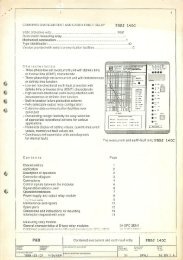
17. Order Form<br />
Earth Fault <strong>Relay</strong> (<strong>MR</strong>-<strong>EF</strong>)<br />
<strong>MR</strong>-<strong>EF</strong><br />
Rated Current, 1A 1<br />
5A 5<br />
Housing:<br />
100 Series Drawout Case<br />
Flush Mounting<br />
Frequency:<br />
50Hz<br />
60Hz<br />
<strong>PBSI</strong> <strong>Ltd</strong> Trading as<br />
P&B ENGINEERING<br />
Bell Vue Works,<br />
Boundary Street,<br />
Manchester.<br />
M12 5NG.<br />
Tel: 0161-230-6363<br />
Fax: 0161-230-6464<br />
Web Site: www.pbeng.co.uk.<br />
e-mail: mail@pbeng.co.uk<br />
P & B ENGINEERING - 27 - ISSUE 1. April 07