WAUKESHA Manuale Inglese UNIVERSAL 1 - Asco Pompe Srl
WAUKESHA Manuale Inglese UNIVERSAL 1 - Asco Pompe Srl
WAUKESHA Manuale Inglese UNIVERSAL 1 - Asco Pompe Srl

Create successful ePaper yourself
Turn your PDF publications into a flip-book with our unique Google optimized e-Paper software.
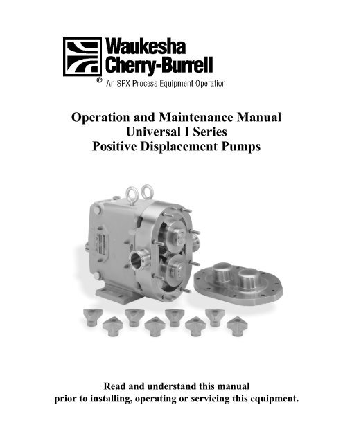
Operation and Maintenance Manual<br />
Universal I Series<br />
Positive Displacement Pumps<br />
Read and understand this manual<br />
prior to installing, operating or servicing this equipment.
611 Sugar Creek Road<br />
Delavan, WI 53115 USA<br />
Tel: (800) 252-5200 (within the USA) • (262) 728-1900<br />
Fax: (800) 252-5012 (within the USA) • (262) 728-4904<br />
E-mail: info@processequipment.spx.com<br />
Website: www.spxprocessequipment.com<br />
Information contained in this manual is subject to change<br />
without notice and does not represent a commitment on<br />
the part of Waukesha Cherry-Burrell. No part of this<br />
manual may be reproduced or transmitted in any form or<br />
by any means, electronic or mechanical, including<br />
photocopying and recording, for any purpose, without the<br />
express written permission of Waukesha Cherry-Burrell.<br />
Copyright © 2006 All Rights Reserved.<br />
Gore-Tex is a registered trademark of W.L. Gore & Associates, Inc.<br />
Kalrez is a registered trademark of DuPont Dow Elastomers.<br />
Chemraz is a registered trademark of Greene, Tweed & Co.<br />
Revised Date: January 2006<br />
Publication: 95-03002
Table of Contents<br />
Safety . . . . . . . . . . . . . . . . . . . . . . . . . . . . . . . . . . . . . . . . . . . . .3<br />
1 Warranty and Receiving . . . . . . . . . . . . . . . . . . . . . . . . . . .4<br />
2 Installation . . . . . . . . . . . . . . . . . . . . . . . . . . . . . . . . . . . . . .5<br />
3 Start-Up Check List . . . . . . . . . . . . . . . . . . . . . . . . . . . . . .10<br />
4 Troubleshooting a Pumping System . . . . . . . . . . . . . . . .11<br />
5 Operation . . . . . . . . . . . . . . . . . . . . . . . . . . . . . . . . . . . . . .16<br />
Lubrication . . . . . . . . . . . . . . . . . . . . . . . . . . . . . . . . . . . . . .16<br />
Fluid Head Disassembly<br />
All Models . . . . . . . . . . . . . . . . . . . . . . . . . . . . . . . . . . . . . .18<br />
Model 320-324 Body Disassembly . . . . . . . . . . . . . . . . . . .19<br />
Model 323A Aseptic Body Disassembly . . . . . . . . . . . . . . .19<br />
Fluid Head Assembly<br />
Most Models . . . . . . . . . . . . . . . . . . . . . . . . . . . . . . . . . . . .20<br />
Flushing Connection . . . . . . . . . . . . . . . . . . . . . . . . . . . . . .21<br />
6 Maintenance . . . . . . . . . . . . . . . . . . . . . . . . . . . . . . . . . . . .22<br />
Visual Checks . . . . . . . . . . . . . . . . . . . . . . . . . . . . . . . . . . .22<br />
“Feel” Checks. . . . . . . . . . . . . . . . . . . . . . . . . . . . . . . . . . . .23<br />
Seal Maintenance . . . . . . . . . . . . . . . . . . . . . . . . . . . . . . . .24<br />
O-Ring - Seals . . . . . . . . . . . . . . . . . . . . . . . . . . . . . . . . . . .24<br />
Mechanical Seals<br />
Universal Series. . . . . . . . . . . . . . . . . . . . . . . . . . . . . . . . . .26<br />
Model 320, 324 . . . . . . . . . . . . . . . . . . . . . . . . . . . . . . . . . .29<br />
Model 323A Aseptic. . . . . . . . . . . . . . . . . . . . . . . . . . . . . . .30<br />
Annual Maintenance . . . . . . . . . . . . . . . . . . . . . . . . . . . . . .32<br />
7 Factory Reconditioning. . . . . . . . . . . . . . . . . . . . . . . . . . .33<br />
8 Disassembly Procedures . . . . . . . . . . . . . . . . . . . . . . . . .34<br />
Shaft Bearing and Gears<br />
All Models . . . . . . . . . . . . . . . . . . . . . . . . . . . . . . . . . . . . . .34<br />
Shaft Removal . . . . . . . . . . . . . . . . . . . . . . . . . . . . . . . . . . .34<br />
All Models except 320,323A and 324 . . . . . . . . . . . . . . . . .35<br />
Models 320, 323A and 324 . . . . . . . . . . . . . . . . . . . . . . . . .36<br />
9 Assembly Procedures . . . . . . . . . . . . . . . . . . . . . . . . . . . .37<br />
Models 6, 12, 15, 18, 22, 30, 32, 34 and 33A Aseptic . . . . .37<br />
Models 320, 323A, 324 Shaft . . . . . . . . . . . . . . . . . . . . . . .39<br />
Gear and Gear Cover Assembly<br />
All Models . . . . . . . . . . . . . . . . . . . . . . . . . . . . . . . . . . . . . .43<br />
Back Face Clearance. . . . . . . . . . . . . . . . . . . . . . . . . . . . . .44<br />
January 2006<br />
Table of Contents<br />
95-03002 Page 1
10 Repair/Reference Tables . . . . . . . . . . . . . . . . . . . . . . . . . 46<br />
Relief Cover . . . . . . . . . . . . . . . . . . . . . . . . . . . . . . . . . . . . 47<br />
Jacketed Cover. . . . . . . . . . . . . . . . . . . . . . . . . . . . . . . . . . 51<br />
Illustrated Parts Lists<br />
006-014-015-018-024-U1 Pump Parts. . . . . . . . . . . . . . . . 52<br />
030-034-033-U1 Pump Parts . . . . . . . . . . . . . . . . . . . . . . . 62<br />
040-U1 Pump Parts . . . . . . . . . . . . . . . . . . . . . . . . . . . . . . 74<br />
060-064-130-134-U1 Pump Parts . . . . . . . . . . . . . . . . . . . 86<br />
220-224-223-U1 Pump Parts . . . . . . . . . . . . . . . . . . . . . . . 96<br />
320-324-323-U1 Pump Parts . . . . . . . . . . . . . . . . . . . . . . 108<br />
Universal I Pump Dimensions . . . . . . . . . . . . . . . . . . . . . 116<br />
Tru-Fit UI Pump Dimensions. . . . . . . . . . . . . . . . . . . . . 118<br />
NOTE: Waukesha Pump CIP Series require use of the<br />
CIP Addendum 95-03039 in conjunction with this manual.<br />
Table of Contents January 2006<br />
Page 2 95-03002
Safety<br />
Warnings, Cautions, and Notes are contained in this manual. To avoid serious<br />
injury and/or possible damage to equipment, pay attention to these<br />
messages.<br />
WARNING: Hazards or unsafe practices which COULD result in<br />
severe personal injury or death and how to avoid it.<br />
CAUTION: Hazards or unsafe practices which COULD result in<br />
minor personal injury or product or property damage.<br />
NOTE: Important information pertaining directly to the subject. This<br />
is information to be aware of when completing the task.<br />
READ AND UNDERSTAND THIS MANUAL PRIOR TO<br />
INSTALLING, OPERATING, OR MAINTAINING THIS PUMP.<br />
January 2006<br />
Safety<br />
95-03002 Page 3
Section 1 - Warranty and Receiving<br />
<strong>WAUKESHA</strong><br />
CHERRY-BURRELL<br />
WARRANTY<br />
FACTORY INSPECTION<br />
RECEIVING<br />
INSPECTON<br />
LOSS OR DAMAGE<br />
WARRANTY<br />
Seller warrants its products to be free from defects in materials and<br />
workmanship for a period of one (1) year from the date of shipment. This<br />
warranty shall not apply to products which require repair or replacement due<br />
to normal wear and tear or to products which are subjected to accident,<br />
misuse or improper maintenance. This warranty extends only to the original<br />
Buyer. Products manufactured by others but furnished by Seller are exempted<br />
from this warranty and are limited to the original manufacturer’s warranty.<br />
Seller’s sole obligation under this warranty shall be to repair or replace any<br />
products that Seller determines, in its discretion, to be defective. Seller<br />
reserves the right either to inspect the products in the field or to request their<br />
prepaid return to Seller. Seller shall not be responsible for any transportation<br />
charges, duty, taxes, freight, labor or other costs. The cost of removing and/or<br />
installing products which have been repaired or replaced shall be at Buyer’s<br />
expense.<br />
Seller expressly disclaims all other warranties, express or implied, including<br />
without limitation any warranty of merchantability of fitness for a particular<br />
purpose. The foregoing sets forth Sellers entire and exclusive liability, and<br />
Buyer’ exclusive and sole remedy, for any claim of damages in connection<br />
with the sale of products. In no event shall Seller be liable for any special<br />
consequential incidental or indirect damages (including without limitation<br />
attorneys’ fees and expenses), nor shall Seller be liable for any loss of profit or<br />
material arising out of or relating to the sale or operation of the products<br />
based on contract, tort (including negligence), strict liability or otherwise.<br />
Each <strong>WAUKESHA</strong> pump is shipped completely assembled, lubricated and<br />
ready for use. (See OPERATION on page 17). The <strong>WAUKESHA</strong> pump is a<br />
precision product, designed to provide long, trouble-free service in a properly<br />
designed system with normal maintenance.<br />
Ports are covered at the factory to keep out foreign objects. If covers are<br />
missing or damaged, a thorough inspection of fluid head, by removing pump<br />
cover, is recommended. Be sure pumping head is clean and free of foreign<br />
material before rotating shaft.<br />
If your pump has been lost or damaged in transit, file a claim at once with the<br />
delivering carrier and ask for an inspector to call. The carrier has signed the<br />
Bill of Lading acknowledging that the shipment has been received from us in<br />
good condition.<br />
We will of course assist you in every way in collecting claims for loss, or<br />
damage, however, we are not responsible for the collection of claims or<br />
replacement of material.<br />
Please read the Warranty statement to correctly determine if you have a<br />
claim. In warranty claims you must have a “Returned Goods Authorization”<br />
(RGA) from the manufacturer before any returns will be accepted. Your<br />
Distributor will help you in a warranty problem.<br />
Section 1 - Warranty and Receiving January 2006<br />
Page 4 95-03002
Section 2 - Installation<br />
The installation of your Waukesha pump and its piping system should follow<br />
good practice to give optimum performance, and to be in accordance with<br />
local codes and restrictions.<br />
All system equipment, such as motors, sheaves, drive couplings, speed<br />
reducers, etc., must be properly sized to ensure satisfactory operation of your<br />
Waukesha pump within its limits.<br />
CAUTION: Waukesha pumps are positive displacement, low slip<br />
design and will be severely damaged if operated with closed valves<br />
in discharge or inlet lines. Pump warranty is not valid for damages<br />
caused by a hydraulic overload from operation or start-up with a<br />
closed valve in the system.<br />
PUMP & DRIVE<br />
INSTALLATION<br />
The installation of your Waukesha pump and its piping system should follow<br />
good practice to give optimum performance.<br />
Pumps of this type and size are generally mounted on a common base plate<br />
with the drive.<br />
WARNING: Full coupling guards must be installed to isolate<br />
operators and maintenance personnel from rotating components.<br />
Coupling guards are provided with Waukesha pumps as a part of a<br />
complete pump and drive package.<br />
NOTE: Pump can be mounted in any of three positions without<br />
removing shafts. However, unless it is an RF pump (14, 34, 64, 134,<br />
224 or 324), mounting it on its side will require more lubrication before<br />
operating (see OPERATION on page 16).<br />
Coupling Guard<br />
The unit can be installed in the plant location in several ways:<br />
Permanent installation on foundation with bolts and grout. (Level unit<br />
before grouting).<br />
Coupling Guard<br />
Leveling and/or vibration isolation pads.<br />
January 2006<br />
Section 2 - Installation<br />
95-03002 Page 5
Coupling Guard<br />
Adjustable leg base, commonly used for sanitary pumps. For washdown<br />
under base. Can be easily moved or repositioned.<br />
Coupling Guard<br />
Portable bases, for movement to different locations.<br />
WARNING: To avoid serious injury, do not install or service pump<br />
unless all power is off and locked out.<br />
GOOD PIPING<br />
PRACTICE<br />
All piping to the pump should be supported independently to minimize the<br />
forces exerted on the pump. Such forces can cause misalignment of pump<br />
parts and lead to excessive wear of rotors, bearings and shafts.<br />
Piping support<br />
Weight of piping and fluid — support piping independently with hangers or<br />
pedestals.<br />
Thermal expansion of piping — can cause tremendous forces. Use thermal<br />
expansion joints to minimize forces on pump.<br />
Flexible joints can also be used to limit the transmission of mechanical<br />
vibration. Anchor free ends of any flexible hose in system.<br />
Piping Layout<br />
Inlet side — slope piping up to inlet to avoid air pocket.<br />
Inlet side — use check valves to keep inlet line full particularly with low<br />
viscosity fluids, and in start-stop operation.<br />
Section 2 - Installation January 2006<br />
Page 6 95-03002
Inlet Vacuum Service — use check valve on outlet side. Prevents backflow (air<br />
or fluid). Facilitates initial start-up (minimizes differential pressure pump must<br />
supply to start flow).<br />
"Isolation" valves — permit pump maintenance and removal safely and<br />
without emptying entire system.<br />
Relief Valve<br />
To protect the pump and piping system against excessive pressure, a relief<br />
valve should be installed. An integral relief valve, designed to bypass the fluid<br />
internally from the pump outlet to the inlet, should not be used on applications<br />
where the discharge must be closed for more than a few minutes. Prolonged<br />
operation of the pump with closed discharge will cause heating of the fluid<br />
circulating through the relief valve. When such operation is necessary, the<br />
relief valve, whether integral, attachable, or line-mounted, should discharge<br />
externally through piping connected to the fluid source, or if that is not<br />
practical, into the inlet piping near the source.<br />
A particular relief valve design will have a characteristic curve such as shown.<br />
The "cracking pressure" can usually be set by spring adjustment, or by<br />
adjustable pneumatic pressure, etc. Flow will begin to bypass when this<br />
"cracking pressure" is reached. As flow increases through the bypass, the<br />
system pressure will also increase.<br />
The pressure increase for a given valve design depends on the valve setting,<br />
the flow rate, and the viscosity of the fluid being pumped. If the full-flow<br />
bypass pressure exceeds the maximum allowable for the particular pump and<br />
piping system, an oversize attachable relief valve may sometimes be used to<br />
limit the full-flow bypass pressure to an acceptable value.<br />
Inlet Side — Strainers and Traps<br />
Inlet side strainers and traps can be used to prevent pump damage from<br />
foreign matter. Selection must be carefully made as clogging can easily occur,<br />
restricting the inlet, causing cavitation and flow stoppage.<br />
Pressure Gauges — Install gauges whenever possible!<br />
Pressure and vacuum gauges provide the easiest way to tell you something<br />
about the pump operation.<br />
• Normal or abnormal pressures<br />
• Overload conditions indication of flow<br />
• Changes in pump condition<br />
• Changes in system conditions<br />
• Changes in fluid viscosity<br />
January 2006<br />
Section 2 - Installation<br />
95-03002 Page 7
Alignment of Pump to Drive<br />
Pumps and drives which are ordered from the factory and mounted on a<br />
common base plate are accurately aligned before shipment. The alignment<br />
should be rechecked after the complete unit has been installed and the piping<br />
completed. Periodic rechecking is advisable during the pump service life.<br />
WARNING: To avoid serious injury, do not install or service pump unless<br />
all power is off and locked out.<br />
In-line Drives<br />
For initial pump installation, and for rechecking alignment, the following steps<br />
are advised:<br />
Use a flexible coupling to connect the drive to the pump. Many different<br />
types are available, including couplings with slip or overload provision.<br />
Feeler or Taper Gauge<br />
Rubber<br />
Cushioned<br />
Gear<br />
Type<br />
Flexible<br />
Member<br />
Detent<br />
Slip<br />
Overload<br />
Fluid<br />
Coupling<br />
A flexible coupling is used to compensate for end play and small<br />
differences in alignment. The pump and drive shaft should be aligned as<br />
closely as is possible.<br />
Check at 4 points around<br />
coupling - every 90°<br />
Shim<br />
as<br />
needed<br />
Check angular alignment<br />
Using feeler gauges, or taper gauges. Adjust to get equal dimension at all<br />
points. At the same time set space between coupling halves to manufacturer’s<br />
recommended distance.<br />
Move drive as needed<br />
Check parallel misalignment:<br />
Use straight edges and shims.<br />
After piping is complete, and drive and couplings are aligned, turn pump shaft<br />
manually to see if it turns freely without binding.<br />
Shim height as needed<br />
WARNING: Keep fingers out of ports.<br />
Section 2 - Installation January 2006<br />
Page 8 95-03002
Check rotation direction of drive to see that pump will rotate in proper<br />
direction. ("Liquid End" of pump is shown below.)<br />
NOTE: Covers have been removed for illustration purposes only. The<br />
pump cannot be operated with the cover removed.<br />
Top Shaft<br />
Drive<br />
Lower Shaft<br />
Drive<br />
Lower Shaft<br />
Drive<br />
Top Shaft<br />
Drive<br />
Figure 1<br />
Determine rotation direction by looking at the motor coupling.<br />
Connect coupling halves and install coupling guard.<br />
Aligning belt and chain drives<br />
Using straight-edges and visual check. Move drive to correct any angular and<br />
parallel misalignment<br />
Keep<br />
distance<br />
to minimum<br />
Figure 2<br />
After piping is complete and before belts are installed, turn pump shaft<br />
manually to see that it turns freely.<br />
Check rotation direction of pump to see that pump will rotate in proper<br />
direction (see Figure 1). Install belts and tension them correctly. Install belt<br />
guard before operation.<br />
January 2006<br />
Section 2 - Installation<br />
95-03002 Page 9
Section 3 - Start-up Check List<br />
The Waukesha Pump is a positive displacement pump and can develop very<br />
high pressures. To protect lines, equipment and personnel, certain<br />
precautions must be taken.<br />
1. Review Section 2, particularly “Relief Valves”. Install relief valves if<br />
needed in system.<br />
2. Check that piping and pump are clean and free of foreign material, such<br />
as welding slag, gaskets, etc. Do not use pump to flush system.<br />
3. See that all piping connections are tight and leak-free. Where possible,<br />
check system with "non-hazardous" fluid.<br />
4. Check to see that pump and drive are lubricated. See Section 5. Check<br />
Drive Lubrication Instruction.<br />
5. Check that all guards are in place and secure.<br />
6. Seals: Double mechanical and double O-ring seals with flushing require<br />
adequate supply and flow of clean flushing fluids.<br />
7. See that all valves are open on discharge system, and that free flow path<br />
is open to destination.<br />
8. See that all valves are open on inlet side, and that fluid can reach pump.<br />
9. Check direction of pump and drive rotation. (See page 10)<br />
10. Start pump drive. Where possible, start at slow speed, or jog.<br />
Check to see that liquid is reaching pump within several minutes. If pumping<br />
does not begin and stabilize, check items under "No Flow" or "Insufficient<br />
Flow" in Section 4 - Troubleshooting a Pumping System (page 12).<br />
Section 3 - Start-up Check List January 2006<br />
Page 10 95-03002
Section 4 - Troubleshooting a Pumping System<br />
Once a pump is properly selected and installed in a system, operation should<br />
be trouble free. However, in existing systems, or as pump and system<br />
conditions change, problems may develop. Following are some<br />
troubleshooting hints to help identify and solve problems.<br />
WARNING: To avoid serious injury, do not install or service pump<br />
unless all power is off and locked out.<br />
WARNING: To avoid possible serious injury, shut off and drain<br />
product from pump prior to disconnecting piping..<br />
Problem Probable Causes Solutions<br />
No flow, pump not turning 1. Drive motor not running.<br />
2. Keys sheared or missing.<br />
3. Drive belts, power transmission<br />
components slipping or broken.<br />
4. Pump shaft, keys, or gears<br />
sheared.<br />
1. Check resets, fuses, circuit<br />
breakers.<br />
2. Replace.<br />
3. Replace or adjust.<br />
4. Inspect: replace parts.<br />
No flow, pump turning Wrong direction of rotation Reverse<br />
No flow, pump not priming 1. Valve closed in inlet line.<br />
2. Inlet line clogged or restricted.<br />
3. Air leaks due to bad seals or pipe<br />
connections.<br />
4. Pump speed too slow.<br />
5. Liquid drains or siphons from<br />
system during off periods.<br />
1. Open valve.<br />
2. Clear line, clean filters, etc.<br />
3. Replace seals; check lines for<br />
leakage (can be done by air<br />
pressure or by filling with liquid<br />
and pressurizing with air).<br />
4. Increase speed. Filling inlet lines<br />
with fluid may allow initial startup.<br />
Foot valve may solve start-up<br />
problems permanently.<br />
5. Use foot valve or check valves.<br />
January 2006<br />
Section 4 - Troubleshooting a Pumping System<br />
95-03002 Page 11
Problem Probable Causes Solutions<br />
No flow, pump not priming 1. "Air" lock. Fluids which "gas off",<br />
or vaporize, or allow gas to come<br />
out of solution during off periods.<br />
2. Extra clearance rotors, worn<br />
pump.<br />
3. Net inlet pressure available too<br />
low.<br />
4. On "Vacuum" inlet system: On<br />
initial start-up, atmospheric “blow<br />
back“ prevents pump from<br />
developing enough differential<br />
pressure to start flow.<br />
No flow 1. Relief valve not properly<br />
adjusted, or held off seat by<br />
foreign material (flow is being<br />
recirculated to inlet).<br />
Insufficient flow 1. Speed too low to obtain desired<br />
flow.<br />
2. Air leak due to bad seals or pipe<br />
connections.<br />
1. Manual or automatic air bleed<br />
from pump or lines near pump.<br />
2. Increase pump speed, use foot<br />
valve to improve priming.<br />
3. Check net inlet pressure<br />
available, net inlet pressure<br />
required, recalculate system.<br />
Change inlet system as needed.<br />
4. Install check valve in discharge<br />
line.<br />
1. Adjust or clear valve.<br />
1. Check flow-speed curve.<br />
2. Replace seals, check inlet<br />
fittings.<br />
Fluid vaporization<br />
(“starved“ pump inlet)<br />
1. Strainers, foot valves, inlet fittings<br />
or lines clogged.<br />
2. Inlet line size too small, inlet line<br />
too long. Too many fittings or<br />
valves. Foot valve, strainers too<br />
small.<br />
3. Net inlet pressure available at<br />
pump too low.<br />
4. Net inlet pressure required by<br />
pump too low.<br />
5. Net inlet pressure available too<br />
low.<br />
6. Fluid viscosity greater than<br />
expected.<br />
7. Fluid temperature higher than<br />
expected (vapor pressure<br />
higher).<br />
1. Clear lines. If problem continues,<br />
inlet system may require change.<br />
2. Increase inlet line size. Reduce<br />
length, minimize direction and<br />
size changes, reduce number of<br />
fittings.<br />
3. Raise liquid level in source tank.<br />
4. Increase by raising or<br />
pressurizing source tank.<br />
5. Select larger pump size with<br />
smaller net inlet pressure<br />
required.<br />
6. Reduce pump speed and accept<br />
lower flow, or change system to<br />
reduce line losses.<br />
7. Reduce temperature, reduce<br />
speed and accept lower flow or<br />
change system to increase net<br />
inlet pressure available.<br />
Section 4 - Troubleshooting a Pumping System January 2006<br />
Page 12 95-03002
Problem Probable Causes Solutions<br />
Insufficient flow. Fluid being<br />
bypassed somewhere<br />
1. Relief valve not adjusted or<br />
jammed.<br />
2. Flow diverted in branch line,<br />
open valve, etc.<br />
1. Adjust or clear.<br />
2. Check system and controls.<br />
Insufficient flow. High slip 1. Hot (HC) or extra clearance<br />
rotors on "cold" fluid, and/or low<br />
viscosity fluid.<br />
2. Worn pump.<br />
3. High pressure.<br />
1. Replace with standard clearance<br />
rotors.<br />
2. Increase pump speed (within<br />
limits). Replace rotors,<br />
recondition pump.<br />
3. Reduce pressure by system<br />
changes.<br />
Noisy operation<br />
Cavitation<br />
1. High fluid viscosity,<br />
High vapor pressure fluids,<br />
High temperature<br />
2. Net inlet pressure available less<br />
than net inlet pressure required,<br />
see Engineering Manual<br />
Air or gas in fluid<br />
1. Leaks in pump or piping<br />
2. Dissolved gas or naturally<br />
aerated products<br />
1. Slow down pump, reduce<br />
temperature, change system.<br />
2. To increase net inlet pressure<br />
available or reduce net inlet<br />
pressure required.<br />
1. Correct leaks.<br />
2. Minimize discharge pressure.<br />
Also see "Cavitation" above.<br />
Mechanical noises - Rotor to body<br />
contact.<br />
1. Improper assembly<br />
1. Check clearance with shims.<br />
January 2006<br />
Section 4 - Troubleshooting a Pumping System<br />
95-03002 Page 13
Problem Probable Causes Solutions<br />
Noisy operation<br />
Pump requires excessive<br />
power (overheats, stalls,<br />
high current draw, breakers<br />
trip)<br />
Rotor to body contact<br />
1. Distortion of pump due to<br />
improper piping installation.<br />
2. Pressure higher than rated.<br />
3. Worn bearing.<br />
4. Worn gears.<br />
Rotor to rotor contact<br />
1. Loose or mis-timed gears,<br />
twisted shaft, sheared keys, worn<br />
splines.<br />
Relief valve chattering<br />
Drive component noise-gear<br />
trains, chains, couplings,<br />
bearings.<br />
1. Higher viscous losses than<br />
expected.<br />
2. Higher pressure than expected.<br />
Fluid characteristics.<br />
1. Fluid colder than expected,<br />
viscosity high.<br />
2. Fluid sets up in line and pump<br />
during shut down.<br />
3. Fluid builds up on pump surfaces<br />
(example, latex, chocolate,<br />
fondants).<br />
1. Reassemble pump or re-install<br />
piping to assure free running.<br />
2. Reduce pressure if possible.<br />
3. Rebuild with new bearings.<br />
Lubricate regularly.<br />
4. Rebuild with new gears.<br />
Lubricate regularly.<br />
1. Rebuild with new parts.<br />
Re-adjust, repair or replace.<br />
Repair or replace drive train.<br />
1. If within pump rating, increase<br />
drive size.<br />
2. Reduce pump speed. Increase<br />
line sizes.<br />
1. Heat fluid. Insulate or heat trace<br />
lines. Use pump with more<br />
running clearances.<br />
2. Insulate or heat trace line. Install<br />
“soft start” drive. Install<br />
recirculating bypass system.<br />
Flush with other fluid.<br />
3. Use pump with more running<br />
clearance.<br />
Section 4 - Troubleshooting a Pumping System January 2006<br />
Page 14 95-03002
Problem Probable Causes Solutions<br />
“Short” pump service life 1. High corrosion rate.<br />
2. Pumping abrasives.<br />
3. Speeds and pressures higher<br />
than rated.<br />
4. Worn bearings and gears due to<br />
lack of lubrication.<br />
5. Misalignment of drive and piping.<br />
Excessive overhung load or<br />
misaligned couplings.<br />
1. Upgrade material of pump.<br />
2. Larger pumps at slower speeds,<br />
can help.<br />
3. Reduce speeds and pressures<br />
by changes in system.<br />
4. Set up and follow regular<br />
lubrication schedule.<br />
5. Check alignment of piping.<br />
Check drive alignment and<br />
loads. (page 10)<br />
January 2006<br />
Section 4 - Troubleshooting a Pumping System<br />
95-03002 Page 15
Section 5 - Operation<br />
NORMAL OPERATION<br />
Normal operation covers a speed range of 0 to 600 RPM and pressure range<br />
of 0 to 200 PSI. Temperature range with standard rotors is -40° to 200°F and<br />
with hot clearance rotors. 180° to 300°F. (For operation at higher<br />
temperatures, consult factory.)<br />
WARNING: Stop pump and lock out all power prior to servicing.<br />
LUBRICATION<br />
The gears are factory lubricated with ISO Grade 320, SAE 140, or AGMA<br />
Number 6EP oil at the quantity shown for top or bottom shaft mounts. (14, 34,<br />
64, 134, 224 and 324 are filled for side mount). If you mount your pump other<br />
than top or bottom shaft drive, check oil level.<br />
The bearings are factory greased with NLGI grade 2 grease.<br />
Change oil every 500 hours. If pump is installed where moisture and<br />
condensation are heavy, change oil more frequently.<br />
Bearings must be greased every 250 hours or less depending on moisture<br />
and condensation conditions. Excess grease will accumulate in the gear case<br />
and can be removed through the cleanout hole covered with plastic plug.<br />
Side Mount Position<br />
Oil Fill<br />
Upper Shaft Drive<br />
Oil Fill or Lower<br />
Shaft Oil Level<br />
Sump Cleanout<br />
Side Mount Position Oil<br />
Level<br />
Lower Shaft Drive Oil Fill or<br />
Upper Shaft Oil Level<br />
Figure 3 Upper Shaft Drive Position of Pump Shown<br />
Section 5 - Operation January 2006<br />
Page 16 95-03002
NOTE: For hot or cold extremes use appropriate lubricant as shown<br />
in Table 1.<br />
Table 1<br />
Type<br />
Oil ISO Grade 320,<br />
SAE 140, or AGMA<br />
Number 6EP<br />
Temperature Range<br />
-10° to 350°F<br />
(-23.3° to 176.6 °C)<br />
Grease<br />
Silicone -20° to 5°F<br />
(-28.8° to -15°C)<br />
NLGI grade 2 5° to 350°F<br />
(-15° to 176.6 °C)<br />
Table 2 - Oil Capacity (Gears)<br />
Model<br />
Top or Bottom Shaft<br />
oz (ml)<br />
Side Mount<br />
oz (ml)<br />
6, 12, 14, 15, 18, 22 1.3 (40) 3.3 (100)<br />
30, 32, 33A, 34 2 (60) 4 (120)<br />
60, 62, 64 6 (170) 9.5 (280)<br />
130, 132, 133A, 134 6 (170) 9.5 (280)<br />
220, 222, 223, 224 11 (320) 20 (600)<br />
320, 324, 323A 17 (500) 44 (1300)<br />
DRIVE LUBRICATION<br />
CLEANING<br />
Refer to drive manufacturer’s manual shipped with unit.<br />
The Waukesha pump is designed to be completely disassembled for thorough<br />
and easy cleaning. Clean the pump every day or at the end of a process.<br />
Disassemble the fluid head as outlined. Remove and clean the O-rings,<br />
sleeves and pump seals.<br />
January 2006<br />
Section 5 - Operation<br />
95-03002 Page 17
FLUID HEAD DISASSEMBLY - ALL MODELS<br />
Soft<br />
Hammer<br />
1. Shut off power, close isolation valves, and disconnect inlet and discharge<br />
lines.<br />
2. Remove wing nuts using soft hammer to loosen them.<br />
3. Remove cover, if it is stuck, loosen it with a soft hammer. Remove and<br />
discard cover O-ring.<br />
O-Ring<br />
4. Remove rotor retaining nuts. Use the special wrench supplied with pump<br />
and hit it sharply with a soft hammer to loosen nuts.<br />
5. Orient rotors perpendicular to each other and remove rotor with both<br />
wings exposed first. Handle rotors with care to avoid knicks and<br />
scratches. If it is stuck tight, use a gear puller or hardwood lever behind<br />
rotor hub to force it off spline.<br />
Apply gear puller here<br />
6. Remove pump body by pulling it straight off studs. Use a soft hammer to<br />
assist if body is stuck tight.<br />
7. See Section 4 for seal disassembly procedure.<br />
8. Clean and inspect body thoroughly.<br />
CAUTION: Body must be reassembled on bearing housing from<br />
which it was removed. Both are identified with same serial number.<br />
Section 5 - Operation January 2006<br />
Page 18 95-03002
MODEL 320 AND 324<br />
BODY DISASSEMBLY<br />
After removing the cover and rotors, remove the four bolts from each seal<br />
gland and slide the gland toward the gear case. Loosen the two socket head<br />
cap screws from the front of the body. Tap the body with a soft hammer to<br />
drive body loose from gear case and dowel pins.<br />
MODEL 323 ASEPTIC<br />
BODY DISASSEMBLY<br />
Gland Bolts (8)<br />
Capscrew (2)<br />
1. Disconnect flushing lines.<br />
2. Remove cap screws from seal flush glands and slide glands back against<br />
gear case.<br />
3. Loosen two socket head cap screws in front of body. Tap body with a soft<br />
hammer to drive body loose from gear case and dowel pins.<br />
File flared end<br />
4. Thoroughly clean the shafts. Remove "flared end" to aid in seal removal.<br />
CLEANING<br />
PROCEDURE<br />
Use a basket or wash tank having the bottom covered with a rubber mat.<br />
Wash parts thoroughly with cleaning compound using brushes and plenty of<br />
fresh warm water at about 125°F. Rinse the parts thoroughly with 170°F water<br />
and store them to permit free draining and natural drying. Reassemble pump<br />
and sterilize it in accordance with accepted sterilizing practices. If chlorine<br />
solution (200 ppm available chlorine) is used, it should leave no residual<br />
deposits which would remain in the pump.<br />
NOTE: Acid cleaners have a much higher metal corrosion rate<br />
andpump parts should remain in acid cleaning solutions no longer<br />
than necessary. Any strong inorganic mineral base acids that are<br />
harmful to your hands would be harmful to pump parts. Due to the<br />
high circulation required, Waukesha Fluid Handling recommends<br />
that its pumps not be used to recirculate cleaning solutions.<br />
January 2006<br />
Section 5 - Operation<br />
95-03002 Page 19
FLUID HEAD ASSEMBLY - MOST MODELS<br />
Seal Assembly See SEAL MAINTENANCE for assembly procedure on all<br />
models.<br />
Body Assembly<br />
1. Slide body over shafts and studs being careful seal components are not<br />
knicked or knocked out of place. Press body firmly against gear case<br />
engaging dowels.<br />
Gear Case<br />
Socket Head<br />
Cap Screw<br />
Head<br />
2. Model 320, 324 and 323A bodies are secured to the gearcase with 2<br />
socket head cap screws thru the head. (For seals see page 31 thru 33).<br />
Rotor Assembly<br />
Assemble a rotor onto shaft engaging the large spline tooth with the large<br />
groove in rotor. Rotate shaft until rotor wings are on vertical centerline. Install<br />
the second rotor and secure both with rotor retaining nuts (clockwise). Lock<br />
the nuts. (See torque table on page 49).<br />
NOTE: CIP pumps have right hand and left hand nuts (12, 22, 32, 62,<br />
132 and 222).<br />
Cover Assembly<br />
1. Install O-ring in cover groove.<br />
2. Mount cover on studs and push it against body being sure O-ring remains<br />
in the groove.<br />
3. Attach wing nuts (clockwise) and tighten by hitting them sharply with a<br />
soft hammer.<br />
Section 5 - Operation January 2006<br />
Page 20 95-03002
Flushing Connection<br />
NOTE: Flushing media may be piped into either side for both shaft<br />
seals and discharged to drain on opposite side. Both inlets may be<br />
manifolded to simplify piping. Be sure flush water is flowing out both<br />
discharge lines.<br />
Restrictor<br />
Low Pressure Flush<br />
1. Set flow rate of approximately 1/4 GPM for most applications. For high<br />
temperature applications increase flow.<br />
2. Flushing media is restricted on inlet side and has free flow to drain on<br />
outlet side.<br />
Flush In<br />
Flush Out<br />
3. Typical flushing connections are 1/8" NPT female pipe taps.<br />
Flush In<br />
Flush Out<br />
Flushing Connection - Aseptic Series<br />
All connections are 1/8" female pipe taps. The pump has double "barriers" or<br />
seals at every opening to the pump chamber. Live steam or a sterile fluid is<br />
circulated between these double seals at the ports, in the cover and at the<br />
shaft seals.<br />
Steam In<br />
Steam In<br />
Steam In<br />
Steam<br />
In<br />
Steam Out<br />
Steam out<br />
Steam Out<br />
Steam Out<br />
Figure 4<br />
January 2006<br />
Section 5 - Operation<br />
95-03002 Page 21
Section 6- Maintenance<br />
GENERAL<br />
In the maintenance of pumps it is important to recognize when parts are<br />
wearing excessively. Detecting wear in the early stages will let you repair your<br />
pump at minimum cost and get it back into operation at the earliest date.<br />
Periodic cleaning and a simple “look-feel” inspection of your pump are<br />
recommended as good operating procedures and as a means of detecting<br />
signs of trouble at an early stage. They require only a few minutes and may<br />
save you an appreciable amount of money.<br />
A more detailed maintenance inspection should be scheduled annually. See<br />
ANNUAL MAINTENANCE, page 34.<br />
The following routine “look-feel” checks are to be made by the system<br />
operator during shut-down periods.<br />
VISUAL CHECKS<br />
Clearance on both sides<br />
1. Check rotor wing tips for indications of metal-to-metal contact between<br />
rotor wings. If this condition exists, the pump should be repaired or<br />
replaced.<br />
must be equal<br />
Table 3<br />
Cause<br />
Worn shaft spline<br />
Replace shaft.<br />
Corrective Measure<br />
Spline<br />
Worn rotor spline<br />
Replace rotor.<br />
Note: Usually both parts will wear. The usual cause is a rotor which<br />
has been loose for extended running periods.<br />
Spline<br />
Loose gears<br />
Worn gears<br />
Twisted shaft<br />
Remove gear and inspect key,<br />
keyway and shaft. If all are in good<br />
condition, reassemble and retighten<br />
gear retainer nuts to specified<br />
torque. (See Table 2, page 49)<br />
Replace gears.<br />
Replace shaft.<br />
2. Check rotor hub end which locks against the shaft shoulder for signs of<br />
wear.<br />
Section 6- Maintenance January 2006<br />
Page 22 95-03002
Wear Area<br />
Cause<br />
Extended running with loose<br />
rotor retaining nuts<br />
Corrective Measure<br />
Replace rotor or reshim shaft to<br />
maintain back face clearance (See<br />
Section 10, Table 1).<br />
3. Shaft shoulder against which rotor hub locates and locks for deterioration.<br />
Shoulder<br />
Cause<br />
“Steps” worn into locating<br />
face by loose rotor<br />
Corrective Measure<br />
Reshim or replace shaft to maintain<br />
correct running clearances. (See<br />
Section 10, Table 1)<br />
“FEEL” CHECKS 1. Gear Back Lash-If there is any free movement when rotating either shaft<br />
without transmitting motion to other shaft, the back lash is excessive.<br />
Cause<br />
Worn gear teeth<br />
Gear loose on shaft<br />
Replace gear.<br />
Corrective Measure<br />
Remove gear and inspect key,<br />
keyway and shaft. If all are in good<br />
condition, reassemble and retighten<br />
gear retaining nuts to specified<br />
torque. (See Section 10, Table 2)<br />
2. Bearing Condition-If movement of either shaft can be detected when hand<br />
loading the rotor end of the shaft (approximately 30 lbs. force applied as<br />
illustrated), bearing may be failing.<br />
Check for<br />
Shaft<br />
Movement<br />
Cause<br />
Lack of lubricant or high<br />
overload<br />
Corrective Measure<br />
Replace bearings and review<br />
lubrication schedule. Check for<br />
means to reduce hydraulic loads.<br />
January 2006<br />
Section 6- Maintenance<br />
95-03002 Page 23
SEAL MAINTENANCE<br />
NOTE: To service seals it is necessary to disassemble fluid head<br />
See FLUID HEAD DISASSEMBLY-ALL MODELS in Section 5 for<br />
procedure<br />
Body O-Ring<br />
O-Ring Service<br />
1. Remove and discard body O-rings, using O-ring removal tool furnished<br />
with pump.<br />
Shaft O-Ring<br />
Stop Pin<br />
Sleeve<br />
2. Remove shaft sleeves and shaft O-rings.<br />
3. Thoroughly clean and inspect grooves, shafts and sleeves.<br />
DO NOT re-use sleeves that are grooved or scratched.<br />
Shaft O-Ring<br />
Prongs<br />
Slotted<br />
Slotted<br />
Sleeve<br />
Assembly<br />
1. Apply an approved O-ring lubricant to NEW O-rings and insert them into<br />
body grooves and shaft grooves. Shaft O-rings should be installed into the<br />
front shaft groove (closest to the shaft spline) when using O-ring seals.<br />
Sleeves may be either slotted or have prongs. Sleeves may be either<br />
slotted or have prongs.<br />
2. Assemble shaft sleeves against shaft shoulder being sure the sleeve<br />
prongs DO NOT line up with the drive pin on shaft. However, do place the<br />
slotted sleeve over the pin if you have that type of sleeve.<br />
3. See Section 5 for fluid head assembly procedure.<br />
Section 6- Maintenance January 2006<br />
Page 24 95-03002
Double O-Ring Service<br />
1. Remove O-ring carriers.<br />
2. Remove and discard O-rings from both body and carriers, using O-ring<br />
removal tool furnished with pump.<br />
Carrier O-Rings<br />
Body O-Ring<br />
Seal Carrier<br />
Pump Body<br />
Shaft O-Ring<br />
Sleeve<br />
3. Remove shaft sleeves and shaft O-rings.<br />
4. Thoroughly clean and inspect body, carrier and shaft grooves, and<br />
sleeves.<br />
DO NOT re-use sleeves that are grooved or scratched.<br />
Assembly<br />
1. Apply an approved O-ring lubricant to NEW O-rings and insert them into<br />
body, carriers and shaft grooves. Shaft O-rings should be installed into the<br />
front shaft groove (closest to the shaft spline) when using O-ring seals.<br />
2. Assemble carriers into body so notch in carrier engages pin in body.<br />
3. Assemble shaft sleeves against shaft shoulder being sure the sleeve<br />
prongs DO NOT line up with the drive pin on shaft.<br />
Drive Pin<br />
Sleeve<br />
4. See Section 5 for fluid head assembly procedure.<br />
January 2006<br />
Section 6- Maintenance<br />
95-03002 Page 25
Mechanical Seal<br />
Service - Single Inside<br />
Seal Seat<br />
O-Ring<br />
1. Remove seal from body, then clean and inspect thoroughly. DO NOT reuse<br />
if seal face is scratched, chipped or cracked.<br />
2. Remove O-rings from body and discard. Use O-ring removal tool supplied<br />
with pump.<br />
3. Dress off shaft shoulder against which rotor bottoms with file to remove<br />
“flared end” and to aid in disassembly of seal seat.<br />
Inner Seal<br />
4. Remove seal seats and shaft O-rings. Clean and inspect thoroughly. DO<br />
NOT re-use seats that are cracked, chipped, scratched or grooved.<br />
File<br />
Assembly - Single Inside<br />
1. Install NEW O-rings on shafts. Lubricate O-rings to aid in assembly of<br />
seal seat.<br />
2. Install seal seats being sure to line up groove on rear face with drive pin<br />
on shaft. Lubricate face of seat.<br />
Seal Seat<br />
Drive Pin<br />
3. Lubricate and insert NEW O-rings in body grooves.<br />
4. Assemble wave spring on seal and install into body with notch engaging<br />
pin in body.<br />
5. Lubricate seal faces.<br />
Shaft O-Ring<br />
6. See Section 5 for fluid head assembly procedure.<br />
Inner Seal<br />
Body O-Ring<br />
Wave Spring<br />
NOTE: Handle all seal components with extreme care<br />
Section 6- Maintenance January 2006<br />
Page 26 95-03002
Service - Single Outer<br />
Seal Seat<br />
O-Ring<br />
1. Remove seals from body and discard O-rings. Inspect seal face<br />
thoroughly. DO NOT re-use seals that are cracked, chipped or scratched.<br />
2. Dress off shaft shoulder against which rotor bottoms with file to remove<br />
“flared end” and to aid in disassembly of seal seat.<br />
Outer Seal<br />
File<br />
3. Remove seal seats and shaft O-rings. Clean and inspect thoroughly. DO<br />
NOT re-use seats that are cracked, chipped, scratched, or grooved.<br />
Seal Seat Drive Pin<br />
Assembly - Single Outer<br />
1. Install NEW O-rings on shafts an lubricate to aid in assembly of seal seat.<br />
2. Install seal seats being sure to line up groove on rear face with drive pin<br />
on shaft. Lubricate face of seat.<br />
Shaft O-Ring<br />
3. Apply lubricant to NEW O-rings for seal and assemble on seals.<br />
Outer<br />
Seal<br />
Pin<br />
4. Insert seal assembly into body engaging notch with pin and pushing from<br />
opposite side, over and in, to seat O-ring.<br />
5. Apply lubricant to seal face.<br />
6. See Section 5 for fluid head assembly procedure.<br />
January 2006<br />
Section 6- Maintenance<br />
95-03002 Page 27
DOUBLE CONCENTRIC<br />
SEALS AND ASEPTIC<br />
MODEL SEALS<br />
Service - Outer Seal<br />
Remove seals from body and discard O-rings. Inspect seas face thoroughly.<br />
DO NOT re-use seals that are cracked, chipped or scratched.<br />
Seal Seat<br />
Spring<br />
“O” Ring<br />
Outer Seal<br />
Inner Seal<br />
File<br />
Service - Inner Seal<br />
1. Remove seal from body, then clean and inspect thoroughly. DO NOT reuse<br />
if seal face is scratched, chipped or cracked.<br />
2. Remove O-rings from body and discard. Use O-ring removal tool supplied<br />
with pump.<br />
3. Dress off shaft shoulder against which rotor bottoms with file to remove<br />
“flared end” and to aid in disassembly of seal seat.<br />
4. Remove seal seats and shaft O-rings. Clean and inspect thoroughly. DO<br />
NOT re-use seats that are cracked, chipped, scratched or grooved.<br />
Seal Seat<br />
Drive Pin<br />
Assembly - Outer Seal<br />
1. Install new O-rings on shafts and lubricate to aid in assembly of seal seat.<br />
NOTE: On aseptic models, there are 2 O-rings per shaft.<br />
Shaft O-Ring<br />
O-Ring<br />
Pin<br />
Seal<br />
Body<br />
2. Install seal seats being sure to line up groove on rear face with drive pin<br />
on shaft. Lubricate face of seat.<br />
3. Apply lubricant to NEW O-rings for seal and assemble on seals.<br />
4. Insert seal assembly into body engaging notch with pin and pushing from<br />
opposite side, over and in, to seat O-ring.<br />
5. Apply lubricant to seal face.<br />
Section 6- Maintenance January 2006<br />
Page 28 95-03002
Pin<br />
Wave Spring<br />
Body O-Ring<br />
Assembly - Inside Seal<br />
1. Lubricate and insert NEW O-rings in body grooves.<br />
2. Assemble wave spring on seal and install into body with notch engaging<br />
pin in body.<br />
3. Lubricate seal faces.<br />
4. See Section 5 for fluid head assembly procedure, seals with a cracked,<br />
chipped or scratched seal face.<br />
NOTE:<br />
damage<br />
Handle all seal components with extreme care to avoid<br />
Capscrew<br />
Lock Washer<br />
Seal<br />
Retainer<br />
File Off Flared<br />
Edges<br />
Seal Seat<br />
Mechanical Seals - Model 320.<br />
Shaft / Seal Service<br />
1. Remove seal from shaft by loosening set screws and sliding off. Dress off<br />
shaft shoulder against which rotor bottoms with file to remove “flared end”<br />
and to aid in disassembly.<br />
2. Clean and inspect seal thoroughly. DO NOT re-use seals with a cracked,<br />
chipped or scratched seal face.<br />
3. Remove seal seat retainer cap screws, lock washers and retainers from<br />
body.<br />
4. Remove seal seat from body. Clean inspect thoroughly. DO NOT re-use a<br />
seal seat that is cracked, chipped, scratched or grooved.<br />
.<br />
NOTE: If one face of seat is worn, the seat can be turned over to<br />
use the other face<br />
January 2006<br />
Section 6- Maintenance<br />
95-03002 Page 29
Capscrew<br />
Gaskets<br />
Seal Face<br />
Assembly<br />
1. Place seal rotating assembly onto shaft with seal face out. Position seal<br />
on shaft (see seal assembly drawing for correct dimension) and lock it<br />
with the set screws.<br />
2. Install seal seat gasket, seal seat, retainer gasket, and seal seat retainer<br />
and secure them with wing nuts.<br />
3. See Section 5 for fluid head assembly procedure.<br />
Retainer<br />
Seat<br />
NOTE: Handle all seal components with extreme care<br />
Mechanical Seals - Model 323 Aseptic<br />
Inner Seal<br />
Service<br />
Seal 1. Remove inner seal by disengaging set screws in seal collar.<br />
Collar<br />
2. Slide inner seal, seal seat and gaskets off shaft.<br />
3. Loosen outer seal set screws and pull seals off shafts. Remove burrs on<br />
shafts where set screws locked to aid in reassembly.<br />
Set Screw<br />
4. Clean and inspect thoroughly all seal components. DO NOT re-use a seal<br />
or seal seat that is cracked, scratched or grooved.<br />
Section 6- Maintenance January 2006<br />
Page 30 95-03002
Seal Retainer<br />
Seal<br />
Seat<br />
Inner<br />
Seal<br />
Assembly<br />
1. Slip outer seals onto shafts and secure them in position with set screws.<br />
See seal drawing for mounting dimension.<br />
2. Slide seal seat retainer, retainer gasket, seal seat, and seat gasket, in that<br />
order, onto shafts and place seal seat against the seat face of outer seal.<br />
Outer Seal<br />
Gaskets<br />
Retainer<br />
Seal Seat<br />
3. Install inner seal with seal face against seal seat and lock in position with<br />
set screws. See seal drawing for mounting dimension.<br />
Gaskets<br />
4. Mount pump body onto bearing housing and be sure seal seats are<br />
located in body counterbores. Secure body with 4 bolts.<br />
Inner Seal<br />
Bolt<br />
Body<br />
Retainer<br />
Seal Seat<br />
5. Place seal seat retainer and retainer gaskets in position and secure with<br />
cap screws.<br />
Cap Screw<br />
January 2006<br />
Section 6- Maintenance<br />
95-03002 Page 31
ANNUAL MAINTENANCE<br />
The same general procedures and corrective measures outlined should be<br />
followed and in addition the following preventive maintenance operations<br />
should be carried out at this annual check out period.<br />
1. Check bearing with a dial indicator for shaft radial play. If deflection is<br />
equal to or greater than rotor to body diametrical clearance (see Section<br />
10, Table 1), replace bearings.<br />
2. Remove gear cover and inspect gears for wear, back lash and looseness.<br />
Re-torque gear retaining nuts to proper torque. (See Section 10, Table 2)<br />
Rotor<br />
Stress<br />
Points<br />
3. Thoroughly inspect rotors for worn splines, bearing shoulder wear, and<br />
stress cracks. Use dye check method to detect any fatigue type cracks<br />
that may develop into serious trouble.<br />
4. Review performance record on pump and check radial and back face<br />
clearances to determine wear and its effect on desired performance.<br />
(SeeSection 10, Table 1)<br />
An adjustment on operating speed can compensate for wear in some<br />
applications. When wear and subsequent performance is objectionable, we<br />
suggest you take advantage of our reconditioning program. (See Section 7)<br />
NOTE: If bearings or shafts are replaced “in the field” extreme care<br />
should be exercised to position the shaft, by shimming, to maintain<br />
sufficient running clearances between the rotor wing faces and the<br />
pump body faces (back face and cover face).<br />
See Section 10, Table 1 and BACK FACE CLEARANCE. If rotors are slightly<br />
out of time, they can be retimed by shimming the gears.<br />
It is important to hold the same back face dimension for both rotors to avoid<br />
crossover interference.<br />
Section 6- Maintenance January 2006<br />
Page 32 95-03002
Section 7 - Factory Reconditioning<br />
Waukesha pumps are designed so that they may be factory reconditioned<br />
twice and backed with a new pump warranty each time.<br />
Factory reconditioning involves replacement of all worn parts such as shafts,<br />
bearings, oil seals, gears, etc.<br />
The pump body and cover are re-machined and new rotors are installed. The<br />
pumps are stamped R-1 or R-2, after the serial number, designating that they<br />
have been reconditioned once or twice.<br />
NOTE: It is advisable to contact factory and furnish the serial<br />
number of any pump being considered for reconditioning.<br />
When pumps require reconditioning it is recommended that they be returned<br />
to Waukesha Fluid Handling with proper purchase order. Where this is not<br />
practical a “reconditioned” pump may be ordered in advance of the actual<br />
return of the pump being replaced.<br />
While a stock of reconditioned pumps is maintained, all sizes may not be<br />
available. Therefore, normal lead time should be anticipated. In these cases<br />
an invoice will be issued for the price of a new pump with credit allowed upon<br />
receipt of the old pump at the factory so that net cost will be that of a<br />
reconditioned pump.<br />
INTERCHANGEABILITY<br />
All new pumps of a given model are identified by a serial number on bearing<br />
housing nameplate and stamped on top of pump body. The housing and body<br />
must be kept together as a unit because of back face clearance. The rotors,<br />
seals and covers can be interchanged between units.<br />
ALL reconditioned pump parts must be kept together as a unit. These are<br />
specially machined and are not interchangeable.<br />
NOTE: If new body is replaced in the field, it is most important to<br />
check back face and front face clearances. (See Section 10, Table 1)<br />
Reshim shafts if required to avoid rotor and cover contact. Both<br />
rotors must have the same clearance to avoid crossover<br />
interference.<br />
January 2006<br />
Section 7 - Factory Reconditioning<br />
95-03002 Page 33
Section 8 - Disassembly Procedures<br />
FLUID HEAD - ALL<br />
MODELS<br />
Follow the instructions under FLUID HEAD DISASSEMBLY - ALL MODELS in<br />
Section 5.<br />
SEALS - ALL MODELS Follow the instructions under SEAL MAINTENANCE in Section 6.<br />
SHAFT BEARING AND<br />
GEARS - ALL MODELS<br />
1. Remove oil drain plug and drain oil.<br />
Capscrew<br />
Gear Case Cover<br />
Gear Case<br />
Lockwasher<br />
Oil Seal<br />
Silicone<br />
Sealant<br />
Oil Drain Plug<br />
2. Remove cap screws from gear case cover.<br />
3. Pull cover off shaft extension. If cover sticks, use soft hammer to loosen it.<br />
Lockwasher<br />
SHAFT REMOVAL<br />
Wood Block<br />
4. Scrape silicone sealant from gear case and cover.<br />
5. Remove oil seal from cover with an arbor press and discard.<br />
6. Straighten locking tab of lockwashers.<br />
7. Prevent shafts from turning by wedging a wooden block between the<br />
gears.<br />
NOTE: Protect liquid end of shafts by wrapping them with tape.<br />
8. Use spanner wrench or drift to remove gear lock nuts. Gears will be<br />
removed later. See step 10 below.<br />
Section 8 - Disassembly Procedures January 2006<br />
Page 34 95-03002
9. Remove front bearing retainer bolts and pull off retainers. Scrape silicone<br />
sealant from retainer and case. (If retainer is stuck, leave it in place; it will<br />
press out when shaft is removed.)<br />
Tape<br />
Retainer<br />
Silicone<br />
Sealant<br />
Retainer Cap Screw<br />
Tape<br />
Grease Seal<br />
Block to Prevent<br />
Shaft Damage<br />
Bearing<br />
Retainer<br />
10. Place housing on an arbor press with liquid end down. Protect shaft ends<br />
with wood or plastic block and press shafts out of housing. (See Section<br />
10, Table 4)<br />
11. Scrape silicone sealant; press out and discard grease seal from front<br />
bearing retainers.<br />
12. Remove shims. If they are to be re-used, identify them with the shaft on<br />
which they were used.<br />
13. Press out and discard both rear grease seals in housing.<br />
Silicone<br />
Sealant<br />
Grease Seal<br />
Shim<br />
ALL MODELS EXCEPT<br />
320, 323A AND 324<br />
1. Use hydraulic press and V-blocks to remove bearings and spacer. (See<br />
Section 10, Table 4)<br />
Bearing<br />
Spacer<br />
Bearing<br />
V-Block<br />
January 2006<br />
Section 8 - Disassembly Procedures<br />
95-03002 Page 35
MODELS 320, 323A<br />
AND 324<br />
2. Remove rear bearing by using V-blocks and a hydraulic press. (See<br />
Section 10, Table 4)<br />
Rear Bearing<br />
V-Block<br />
3. Secure shaft assembly in a soft jawed vise as shown. Open tab in lock<br />
washer. Remove front bearing lock nut using a spanner wrench or drift<br />
punch.<br />
Lock Nut<br />
Front<br />
Bearing<br />
4. Remove front bearings using V-Blocks and a hydraulic press. (See<br />
Section 10, Table 4)<br />
5. Clean and inspect all parts thoroughly if they are to be re-used.<br />
V-Block<br />
Section 8 - Disassembly Procedures January 2006<br />
Page 36 95-03002
Section 9 - Assembly Procedures<br />
ALL MODELS EXCEPT<br />
MODEL 320, 323A AND<br />
324)<br />
Grease<br />
Shaft Assembly<br />
Front Bearing Assembly<br />
1. Coat front bearing area of shaft with NLGI grade 2 grease. Place upright<br />
in hydraulic press with spline end down.<br />
2. Unwrap front bearing assembly.<br />
Shield<br />
Press Against<br />
Inner Race<br />
Only<br />
Front<br />
Bearing<br />
3. Place front bearing over shaft with shield side up. Press onto shaft until<br />
sealed against shaft shoulder. (See Section 10, Table 4)<br />
Front Bearing<br />
Bearing<br />
Press Against<br />
Inner Race<br />
Only<br />
4. Place spacer over shaft onto bearing.<br />
5. Coat shaft rear bearing area with NLGI grade 2 grease.<br />
6. Slip rear bearing over shaft with shield side down. Press bearing onto<br />
shaft until it seals against spacer and front bearing.<br />
Gear Case Assembly<br />
Shaft Installation<br />
1. Place gear case on arbor press.<br />
Liquid End<br />
GearCase<br />
Front Face<br />
2. To determine the shim thickness required for the front bearing, measure<br />
dimension “A” in the gear case and dimension “B” on the shaft to three<br />
decimal places (1.000, for example). Also refer to the following table for<br />
the shim deduct factor to use with each pump.<br />
January 2006<br />
Section 9 - Assembly Procedures<br />
95-03002 Page 37
Table 4<br />
Pump Model<br />
Deduct Factor<br />
6, 12, 14, 15, 18, 22 .482<br />
30, 32, 33A, 34 .372<br />
Shim<br />
Using these values calculate the shim thickness as follows:<br />
Dimension “A” minus dimension “B” minus shim deduct factor = required shim<br />
thickness.<br />
Shim Here If<br />
Required<br />
050-060<br />
Clearance<br />
Front Bearing Shim<br />
3. Use standard shim packs to equal the required shim thickness. Place<br />
against shoulder in front bearing bore. (Also see Section 10)<br />
4. Install shaft assemblies in gear case with spline end up and drive shaft in<br />
proper location to give top or bottom drive as required. Press shafts into<br />
housing until sealed against shim pack. (See Section 10, Table 4)<br />
5. Place body on gear case and seat it firmly. Install rotors on shafts and<br />
lock them in place with rotor nuts.<br />
Check back face clearance (Dimensions in Section 10, Table 1). Remove<br />
shafts to adjust shim thickness to achieve required back face dimension.<br />
Bearing<br />
Retainer<br />
6. Secure shaft assemblies in gear case with bearing retainers. No silicone<br />
sealant at this time.<br />
NOTE: Retainer must seat firmly against bearing and leave .040 -<br />
.050" clearance with gear case. Use shims between bearing and<br />
retainer if required.<br />
Silicone Sealant<br />
Seal<br />
7. Check back face clearance again. See Section 10, Table 4 and BACK<br />
FACE CLEARANCE.<br />
8. Remove bearing retainers.<br />
9. Grease front and rear bearing through grease fittings until grease is<br />
visible around ball assemblies.<br />
10. Install grease seals in bearing retainers and coat seal lips with NLGI<br />
grade 2 grease. Coat retainer flanges with silicone sealant.<br />
Fill with NLGI grade 2<br />
11. Install bearing retainers.<br />
Section 9 - Assembly Procedures January 2006<br />
Page 38 95-03002
Rear Seal Assembly<br />
1. Install spacer seals and gear spacers.<br />
2. Coat lip of seals with NLGI grade 2 grease.<br />
3. Press in rear seals with lip facing out.<br />
Gear Spacer<br />
Seal (Lip Faces Out)<br />
Spacer Seal<br />
MODELS 320, 323A<br />
AND 324<br />
Shaft Assembly<br />
Grease<br />
Front Bearing Assembly<br />
1. Coat front bearing area of shaft with NLGI grade 2 grease. Place upright<br />
in hydraulic press with spline and down.<br />
2. Unwrap front bearing assembly. Do not interchange parts of one bearing<br />
assembly with another. These parts are precisely matched in manufacture<br />
and must be installed as a matched assembly.<br />
Spacer<br />
Cone and Roller<br />
Radius<br />
Cone and<br />
Roller<br />
Spacer<br />
Cup<br />
Cone and Roller<br />
3. Lift cone and roller assembly out of bearing stack and place on shaft with<br />
radius down as shown. Press onto shaft until seated against shaft<br />
shoulder. (See Section 10, Table 4)<br />
4. Place spacer over shaft onto bearing cone.<br />
5. Place bearing cup over cone and roller assembly, keeping the cup<br />
oriented with proper roller assembly.<br />
6. Coat remaining bearing cone and roller I.D. with NLGI grade 2 grease and<br />
slip them over shaft with roller radius up. Press onto shaft and into cup to<br />
complete assembly of front bearing on shaft. (See Section 10, Table 4)<br />
Cup<br />
7. Apply NLGI grade 2 grease to threaded area on shaft and face of lock nut.<br />
8. Install spacer, lock washer and lock nut. Tighten nut finger tight.<br />
January 2006<br />
Section 9 - Assembly Procedures<br />
95-03002 Page 39
Lock Nut<br />
Lock<br />
Washer<br />
Spacer<br />
9. Clamp shaft behind lock nut in soft jawed vise and drive lock nut tight<br />
using a spanner wrench or drift. (See Section 10, Table 2.)<br />
Lock Nut<br />
Cup<br />
Spacers<br />
Cup<br />
Cone and Roller<br />
Grease<br />
Retainer<br />
Spacer<br />
(320 & 323)<br />
10. Bend lock washer tab into groove on nut to secure assembly.<br />
Rear Bearing Assembly<br />
1. Unwrap rear bearing assembly. Do not interchange parts of the bearing<br />
assembly with another. These parts are precisely matched in manufacture<br />
and must be installed as a matched assembly.<br />
2. Place shaft upright in an arbor press with gear end up. Slip on grease<br />
retainer with flange up.<br />
NOTE: On 320 and 323 install spacer before grease seal.<br />
3. Coat shaft bearing area with Molykote grease. Slip bearing cone and<br />
roller assembly with radius down onto shaft and press on. (See Section<br />
10, Table 4.)<br />
Section 9 - Assembly Procedures January 2006<br />
Page 40 95-03002
Cup<br />
Spacers<br />
4. Apply Molykote grease again. Slip bearing cup over roller assembly.<br />
Install both inner and outer/spacers. Place remaining cup onto outer<br />
spacer and press on the remaining cone and roller assembly. (See<br />
Section 10, Table 4.)<br />
Cup<br />
NOTE: Be sure outer spacer is concentric on shaft.<br />
Bearing Housing Assembly<br />
Shaft Installation<br />
1. Place bearing housing on arbor press. Install front bearing grease seals,<br />
with lip towards center of cavity, flush with back face of bore.<br />
Shim<br />
Flush<br />
Grease Seal<br />
2. Coat lip seals with NLGI grade 2 grease<br />
3. Place standard shim packs into place against shoulder in front bearing<br />
bore.<br />
4. Install shaft assemblies in bearing housing with spline end up and drive<br />
shaft in proper location to give top or bottom drive as required. Press shaft<br />
into housing until seated against shim pack. (See Section 10, Table 4.)<br />
5. Install grease in bearing retainers and coat seal lip with NLGI grade 2<br />
grease, and apply silicone sealant.<br />
Silicone Sealant<br />
Seal<br />
Fill with NLGI grade 2<br />
January 2006<br />
Section 9 - Assembly Procedures<br />
95-03002 Page 41
6. Grease front and rear bearing through grease fittings until grease is<br />
visible around roller assemblies.<br />
7. Secure shaft assemblies in housing with bearing retainers.<br />
Shim Here if Required<br />
See Note<br />
8. Check back face clearance. See Section 10,Table 1 and BACK FACE<br />
CLEARANCE.<br />
Retainer<br />
NOTE: Retainer must bottom out against bearing and leave .015 -<br />
.040" clearance with housing. Use shims between bearing and<br />
retainer if required.<br />
Gear Spacer<br />
Spacer Seal<br />
Rear Seal Assembly<br />
1. Install spacer seals and gear spacers.<br />
2. Coat lip of seals with ISO GradeNLGI grade 2 grease<br />
Seal (Lip Up)<br />
3. Press in rear seals with lip facing out.<br />
NOTE: On Model 60, 130 and 320 pumps rear seal is pressed in<br />
flush with housing. On Model 220 pumps the rear seal must not be<br />
flush. It must be 1/8 inch outside of housing.<br />
Section 9 - Assembly Procedures January 2006<br />
Page 42 95-03002
GEAR AND GEAR<br />
COVER ASSEMBLY -<br />
ALL MODELS<br />
1. Place keys into shaft key slots. Then slide gear with single punch mark<br />
onto drive shaft. Slide gear with two punch marks onto the short shaft with<br />
punch marks straddling single mark of drive gear.<br />
NOTE: Rotors must be at right angles. Shim a gear out to obtain<br />
proper timing if necessary.<br />
2. Secure shafts from turning with a wood block wedged between gears or<br />
rotors.<br />
3. Apply ISO GradeNLGI grade 2 grease to threaded area on shafts and<br />
face of lock nuts.<br />
Lock Washer<br />
Tab<br />
4. Slip on lock washers and lock nuts. Tighten lock nuts with a spanner<br />
wrench or drift. Bend locking tab to secure. See Section 10, Table 2 for<br />
proper torque limit.<br />
5. Press new oil seal into gear cover.<br />
6. Place silicone sealant on back of gear cover and mount cover assembly<br />
over shaft extension onto gear case. Secure with cap screws.<br />
Oil Fill<br />
7. Fill gear cover with ISO Grade 320, SAE 140, or AGMA Number 6EP oil<br />
to proper level. (See OPERATION) Install oil fill plug.<br />
Oil Level<br />
January 2006<br />
Section 9 - Assembly Procedures<br />
95-03002 Page 43
BACK FACE<br />
CLEARANCE<br />
1. Waukesha Pumps are designed with close running clearances. The rotors<br />
are secured against a shaft shoulder with rotor jam nuts. The shaft is<br />
position is controlled with shims behind the front bearing. The front<br />
bearing is secured in the gear case with the bearing retainers. The<br />
resultant clearance between body back face and rotor wing is the back<br />
face clearance A. (See Section 10, Table 1 for required clearance.)<br />
2. To check back face clearance mount body, less seals, onto housing.<br />
Assemble rotors and secure with rotor jam nuts. Measure clearance<br />
between body back face and rotor wing with feeler gauges. Check<br />
readings against recommended back face clearance A in Table 1. Make<br />
note of corrections required and follow examples to determine exact<br />
adjustment to make and avoid unnecessary assembly/disassembly.<br />
3. To make shim adjustments remove rotors, body and shafts. (See Section<br />
8). Make required shim adjustment and reassemble. Recheck back face<br />
clearances. Be sure both rotors have the same clearance to avoid<br />
crossover interference. Examples:<br />
Front Bearing<br />
Rear<br />
Shim<br />
Back Face<br />
Clearance<br />
A<br />
Rotor<br />
To Body<br />
Pump<br />
Body<br />
B<br />
C<br />
Front<br />
Face<br />
Clearance<br />
Too Much Back Face Clearance A<br />
Condition 1<br />
(“A” is more than specified in Table 1)<br />
Correction: A (measured) minus A (Table 1) = shims to remove from rear<br />
outer race of front bearing.<br />
Condition 2<br />
(Rotor wing face projects past body front face.)<br />
Correction: C (measured with depth micrometer) plus C (Table 1) = shims to<br />
remove from rear of front bearing.<br />
Section 9 - Assembly Procedures January 2006<br />
Page 44 95-03002
Not Enough Back Face Clearance A<br />
(A is less than specified in Table 1.)<br />
Correction: A (Table 1) minus A (measured) = shims to add to rear outer race<br />
of front bearing.<br />
NOTE: It is generally best to keep back face clearance to a<br />
minimum.<br />
The back face clearance for both rotors must be equal to avoid rotor crossover<br />
interference with adjacent rotor hub.<br />
January 2006<br />
Section 9 - Assembly Procedures<br />
95-03002 Page 45
Notes<br />
Section 9 - Assembly Procedures January 2006<br />
Page 46 95-03002
Section 10 - Reference Tables and Repair Parts List<br />
Series<br />
15<br />
30<br />
60<br />
130<br />
220<br />
320<br />
Model<br />
12, 14, 15, 18, 22<br />
30, 32, 33A, 34<br />
60, 62, 64,<br />
130, 132, 133A, 134<br />
220, 222, 223A, 224<br />
320, 323A, 324<br />
Table 1 Clearances a<br />
Model<br />
Application<br />
A<br />
Back Face<br />
B<br />
Rotor to Body<br />
a. For non-standard rotor clearance, contact Application Engineering at<br />
Wauksha Cherry-Burell<br />
C<br />
Front Face<br />
6 Standard .002 .003 .005<br />
12 Standard .002 .003 .008<br />
14<br />
15<br />
Standard .002 .003 .005<br />
18 Standard .002 .003 .005<br />
22 Standard .002 .003 .008<br />
30<br />
34<br />
Standard .002 .003 .005<br />
32 Standard .002 .003 .008<br />
33A Standard .002 .003 .007<br />
60<br />
64<br />
Standard .003 .005 .007<br />
62 Standard .003 .005 .010<br />
130<br />
134<br />
Standard .003 .005 .006<br />
132 Standard .003 .005 .011<br />
133A Standard .003 .005 .007<br />
220<br />
224<br />
Standard .005 .006 .007<br />
222 Standard .005 .006 .013<br />
223A Standard .005 .005 .006<br />
320<br />
324<br />
Standard .006 .007 .010<br />
323A Standard .006 .007 .010<br />
January 2006<br />
Section 10 - Reference Tables and Repair Parts List<br />
95-03002 Page 47
Table 2 Torque Values-Ft-Lbs<br />
Series<br />
Lock Nuts<br />
Bearing Gear Rotor<br />
15<br />
30<br />
60, 130<br />
220<br />
320<br />
150<br />
240<br />
360<br />
75<br />
100<br />
140<br />
230<br />
320<br />
30<br />
60<br />
75<br />
150<br />
190<br />
Table 3 Suggested Shims<br />
Series STD. Pump New Shaft<br />
15<br />
30<br />
60, 130<br />
220<br />
320<br />
.113<br />
.113<br />
.125<br />
.125<br />
.125<br />
.110<br />
.110<br />
.120<br />
.120<br />
.120<br />
Table 4 Arbor or Hydraulic Press Required - Tons<br />
Series<br />
Shaft<br />
Front Bearing<br />
Housing<br />
Rear Bearings<br />
Shaft<br />
In Out On Off In Out On Off<br />
15<br />
30<br />
60, 130<br />
220<br />
320<br />
.25<br />
.25<br />
.5<br />
.5<br />
.5<br />
.5<br />
.5<br />
1<br />
1<br />
1<br />
.5<br />
.5<br />
2<br />
5<br />
5<br />
1<br />
1<br />
5<br />
15<br />
20<br />
.5<br />
.5<br />
1<br />
1<br />
3<br />
5<br />
5<br />
5<br />
15<br />
20<br />
Relief Cover Option (Vented Cover)<br />
The optional Relief Cover Feature (also called Vented Cover) is an adjustable,<br />
internal by-pass arrangement which can be used for control of pressure and/<br />
or flow. It is bidirectional; that is the pump flow or rotation can be in either<br />
direction.<br />
This option doesn’t provide fill flow relief for all pumping situations.<br />
The pressure down stream of the pump may increase with increasing amount<br />
of by-pass through the Relief Cover. Actual down stream pressure will depend<br />
on pump speed, product viscosity, and the relief set point (spring adjustment<br />
or air pressure). Avoid high flow rates through the cover with high viscosity<br />
products. The resulting pressure may be greater than the maximum rating of<br />
the pump or other system components. Install a pressure gauge and measure<br />
pressure under worst conditions of maximum flow and maximum viscosity to<br />
determine the maximum pressure for your process. Under any conditions, if<br />
there is a complete flow shut off down stream, stop the pump as soon as<br />
possible. Continued pump operation with the entire flow by-passing will<br />
rapidly build heat within the pump body. Contact Waukesha Application<br />
Engineering for assistance.<br />
Section 10 - Reference Tables and Repair Parts List January 2006<br />
Page 48 95-03002
Three types of Relief Covers are available:<br />
2 4 7 5 3 6 8<br />
Manual<br />
By-pass pressure is adjusted by a threaded adjusting screw (2) which<br />
compresses a spring (5). Several spring sizes are available, to cover a range<br />
of operating pressures.<br />
1<br />
11 10 9 1<br />
Pneumatic<br />
By-pass pressure is adjusted by regulated air or gas pressure, operating on<br />
the side of a diaphragm (9) opposite the pumped fluid. Most sensitive control<br />
of the three types.<br />
16 15 14 13 1<br />
Piston<br />
By-pass pressure is adjusted by regulated air or gas pressure, operating on<br />
the side of a metal piston (12), opposite the pumped fluid. Extended pressure<br />
range possible.<br />
12 17<br />
NOTE: On all types of relief covers, the temperature and chemical<br />
resistance of the elastomer diaphragms and O-rings determine the<br />
useful range.<br />
Buna-N.............. Material supplied as standard<br />
Silicone Rubber. Optional material upon request<br />
January 2006<br />
Section 10 - Reference Tables and Repair Parts List<br />
95-03002 Page 49
Installation Adjustment<br />
Manual<br />
1. Manual: Turn adjusting screw counterclockwise to its farthest position, then<br />
clockwise until light spring pressure is felt.<br />
Adjusting Screw<br />
2. Pneumatic and Piston:<br />
A. Set air/gas pressure to 2-5 PSIG<br />
B. Turn on pump.<br />
C. With pressure gauge and valve in discharge line:<br />
1. Close discharge valve.<br />
2. Turn adjusting screw clockwise until desired relief pressure<br />
registers on gauge. Lock adjusting screw with lock nut.<br />
3. Open valve in discharge line. Relief cover is set and will open<br />
if system pressure exceeds preset limit.<br />
D. Without pressure gauge in discharge line:<br />
1. Turn adjusting screw clockwise and observe product flow at<br />
discharge of system.<br />
2. When product flow reaches maximum or desired flow rate,<br />
lock adjusting screw with lock nut.<br />
3. Pneumatic and Piston:<br />
A. With pressure gauge and valve in discharge line:<br />
1. Close discharge valve slowly and observe gauge pressure.<br />
DO NOT ALLOW PRESSURE TO EXCEED 200 PSI.<br />
2. Increase air/gas pressure, until desired relief pressure<br />
registers on gauge. Lock air/gas pressure regulator adjusting<br />
screw with lock nut.<br />
3. Open valve in discharge line. Relief cover is set and will open<br />
if system pressure exceeds preset limit.<br />
B. Without pressure gauge in discharge line:<br />
1. Increase air/gas pressure to relief valve, with regulator, and<br />
observe product flow at discharge of system.<br />
2. When product flow reaches maximum or desired flow rate,<br />
lock regulator adjusting screw with lock nut.<br />
Section 10 - Reference Tables and Repair Parts List January 2006<br />
Page 50 95-03002
Jacketed Cover Available on Models 6, 15, 18, 30, 60, and 130<br />
The jacketed cover is designed to allow circulation of a heating or cooling<br />
medium. The purpose is to help preheat or cool the pumping head and<br />
sustain operating temperature during short shut down periods. It should not<br />
be used as a heat exchanger to control pumping temperature during<br />
operation<br />
NOTE:<br />
NOTE: Pressure limit for cover media is 60 PSI.<br />
Model Number<br />
6, 15, 18 and 30<br />
3/4" Pipe Tap<br />
60 and 130<br />
1" Pipe Tap<br />
Pump Jackets<br />
Split cast aluminum jackets with cast in pipe passages are available for higher<br />
pressures and temperatures. Consult factory for recommendations.<br />
NOTE:<br />
NOTE: Jacketed pumps require longer mounting studs in the<br />
gearcase. Use a special offset rotor wrench to remove rotors from<br />
006 through 060 models to avoid hitting studs.<br />
Model<br />
Part Number<br />
006-018 AD0 019 001<br />
030 CD0 019 001<br />
060-130 060 019 001<br />
January 2006<br />
Section 10 - Reference Tables and Repair Parts List<br />
95-03002 Page 51
ITEM<br />
NO.<br />
1<br />
7<br />
8<br />
9<br />
006 - 014 - 015 - 018 - 024-UI Pump Parts List<br />
006-U1 Pump Body 1 See Note 1 1<br />
006-U1 Pump Body with Flush 1 See Note 1 1<br />
015-U1 Pump Body 1 See Note 1 1<br />
015-U1 Pump Body with Flush 1 See Note 1 1<br />
014-U1 Rectangular Flange Inlet Body 1 See Note 1 1<br />
014-U1 Rect. Flange Inlet Body with Flush 1 See Note 1 1<br />
018-U1 Pump Body 1 See Note 1 1<br />
018-U1 Pump Body with Flush 1 See Note 1 1<br />
024-U1 Rectangular Flange Inlet Body 1 See Note 1 1<br />
024-U1 Rect. Flange Inlet Body with Flush 1 See Note 1 1<br />
006-014-015-U1 Drive Shaft 1 015 008 000 3<br />
006-014-015-U1 Drive Shaft 1 114642 4<br />
018-024-U1 Drive Shaft 1 018 008 000 3<br />
018-024-U1 Drive Shaft 1 114644 4<br />
006-014-015-U1 Short Shaft 1 015 009 000 3<br />
006-014-015-U1 Short Shaft 1 114643 4<br />
018-024-U1 Short Shaft 1 018 009 000 3<br />
018-024-U1 Short Shaft 1 114645 4<br />
006-U1 Rotor, Twin Wing, Alloy 88 2 006 010 000 2<br />
006-U1 Rotor, Twin Wing, 316SS 2 006 010 200 2<br />
006-U1 Rotor, Single Wing, Alloy 88 2 117238 2, 12<br />
014-015-U1 Rotor, Twin Wing, Alloy 88 2 015 010 000 2<br />
014-015-U1 Rotor, Twin Wing, 316SS 2 015 010 200 2<br />
015-U1 Rotor , Single Wing, Alloy 88 2 117255 2, 12A, 13<br />
018-024-U1 Rotor, Twin Wing, Alloy 88 2 018 010 000 2<br />
018-024-U1 Rotor, Twin Wing, 316SS 2 018 010 200 2<br />
018-U1 Rotor, Single Wing, Alloy 88 2 117273 2, 12B, 13<br />
10A 006-015-U1 Stud 8 AD0 011 000<br />
10B 006-015-U1 Stud, Jacketed Cover 8 AD0 011 J00<br />
10C<br />
10D<br />
DESCRIPTION<br />
QTY.<br />
PER<br />
PUMP<br />
PART<br />
NO.<br />
014-U1 Stud 6 AD0 011 000<br />
014-U1 Stud 2 35547<br />
014-U1 Stud, Jacketed Cover 6 AD0 011 J00<br />
014-U1 Stud, Jacketed Cover 2 35548<br />
10E 018-U1 Stud 8 018 011 000<br />
10F 018-U1 Stud, Jacketed Cover 8 AD0 011 100<br />
10G<br />
10H<br />
NOTES<br />
024-U1 Stud 6 018 011 000<br />
024-U1 Stud 2 35547<br />
024-U1 Stud, Jacketed Cover 6 AD0 011 100<br />
024-U1 Stud, Jacketed Cover 2 35548<br />
Stud Retainer Assembly 1 020 064 000 5<br />
NOTES:<br />
1. Contact Factory with Serial Number of pump for<br />
Part Number.<br />
2. Standard clearances and finishes for Rotor Part<br />
Numbers shown. Contact Factory for optional<br />
clearances and finishes.<br />
3. Pumps shipped prior to July 30, 2001.<br />
4. Pumps shipped starting July 30, 2001.<br />
5. No longer manufactured, consult factory for<br />
upgrade of gear case subassembly.<br />
12. Replaces 006 010 010 straight and 006 010 090<br />
90° (degree) rotors.<br />
12A.Replaces 015 010 010 straight and 015 010 090<br />
90° (degree) rotors.<br />
12B.Replaces 018 010 010 straight and 018 010 090<br />
90° (degree) rotors.<br />
13. Single wing rotors can not be used in Rectangular<br />
Flange Inlet pumps.<br />
Section 10 - Reference Tables and Repair Parts List January 2006<br />
Page 52 95-03002
006 - 014 - 015 - 018 - 024-UI Pump Parts Diagram<br />
January 2006<br />
Section 10 - Reference Tables and Repair Parts List<br />
95-03002 Page 53
ITEM<br />
NO.<br />
006 - 014 - 015 - 018 - 024-UI Common Parts List<br />
DESCRIPTION<br />
QTY.<br />
PER<br />
PART<br />
NO.<br />
PUMP<br />
Pump Cover 1 AD0 002 S00<br />
Jacketed Cover 1 AD0 002 J10<br />
2<br />
Pump Cover Vented - Complete Assembly<br />
Manual (over 150 PSI) 1 CVR00027<br />
Manual (under 150 PSI) 1 CVR00006<br />
Pneumatic 1 CVR00004<br />
Piston 1 CVR00005<br />
Gear Case, CI 1 020 005 000 3, 5<br />
3<br />
Gear Case, SS; Optional 1 101830 3, 5<br />
Gear Case, CI 1 102276 4<br />
Gear Case, SS; Optional 1 101831 4<br />
4<br />
Gear Case Cover, Steel 1 020 106 000<br />
Gear Case Cover, SS; Optional 1 102280<br />
5 Gear, Drive Shaft, Spur 1 107997<br />
6 Gear, Short Shaft, Spur 1 107997<br />
11<br />
Wing Nut 8 105850<br />
Hex Nut, optional 8 108369<br />
12 Oil Seal, Gear Case Cover 1 000 030 016<br />
13 Oil Seal, Gear Case Rear 2 000 030 017<br />
Grease Seal, Bearing Retainer 2 000 030 018 3<br />
14<br />
Grease Seal, Bearing Retainer 2 121679 4<br />
Bearing Isolator Kit, includes Bearing Retainer 2 X06636-1 3<br />
Bearing Isolator Kit, includes Bearing Retainer 2 X06638-1 4<br />
15 Bearing, Rear 2 015 035 000<br />
16<br />
Bearing, Front 2 015 036 000 3<br />
Bearing, Front 2 101714 4<br />
17 Key, Gear 2 015 037 000<br />
19 Drive Pin, Seal Seat and Sleeve 2 CD0 126 000<br />
20 Dowel Pin, Upper Cover Side 1 AD0 040 000<br />
21 Dowel Pin, Upper Gear Case Side 1 AD0 040 R00<br />
22 Dowel Pin, Lower Cover Side 1 AD0 040 100<br />
23 Dowel Pin, Lower Gear Case Side 1 AD0 040 R10<br />
24 Fill, Drain, Level Plug 6 000 046 002<br />
25 Silicone Sealant 1 000 142 301<br />
26 Jam Nut, Rotor 4 AD0 052 001<br />
27<br />
Shim, Front Bearing AR 015-054-XXX 3<br />
Shim Kit 2 117889 4<br />
29 Spacer, Gear to Rear Bearing 2 015 055 000<br />
30<br />
Bearing Spacer 2 015 055 001 3<br />
Bearing Spacer 2 101814 4<br />
NOTES:<br />
3. Pumps shipped prior to July 30, 2001.<br />
4. Pumps shipped starting July 30, 2001<br />
5. No longer manufactured, consult factory for upgrade of gear case subassembly.<br />
NOTES<br />
Section 10 - Reference Tables and Repair Parts List January 2006<br />
Page 54 95-03002
006 - 014 - 015 - 018 - 024-UI Common Parts Diagram<br />
January 2006<br />
Section 10 - Reference Tables and Repair Parts List<br />
95-03002 Page 55
ITEM<br />
NO.<br />
006 - 014 - 015 - 018 - 024-UI Common Parts List<br />
DESCRIPTION<br />
QTY.<br />
PER<br />
PART<br />
NO.<br />
NOTES<br />
PUMP<br />
32<br />
Bearing Retainer, Front 2 015 080 000 3<br />
Bearing Retainer, Front 2 101810 4<br />
1/4-20 x .75" HHCS, Standard 14 30-287<br />
33A, 33B<br />
1/4-20 x .75" HHCS, SS 14 30-58<br />
33C 1/4" Flat Washer, Gear Case Cover 6 43-108<br />
34 Dowel Bushing, Upper 1 AD0 116 000<br />
35 Dowel Bushing, Lower 1 AD0 116 100<br />
* O-Ring, Pump Cover, Buna N 1 N70252<br />
* O-Ring, Pump Cover, EPDM 1 E70252<br />
36<br />
* O-Ring, Pump Cover, FKM 1 V70252<br />
* O-Ring, Pump Cover, Silicone 1 S75251<br />
* 014-U1 O-Ring, Rectangular Flange 1 N70241<br />
* 36B 024-U1 O-Ring, Rectangular Flange 1 N70241 14<br />
* 024-U1 O-Ring, Rectangular Flange 1 N70245 14<br />
37 Stop Pin, Seal 2 015 126 000<br />
39 Lockwasher, Gear 2 STD 136 005<br />
41 Locknut, Gear 2 STD 236 005<br />
Gear Case Shim, CI 1 020 110 000<br />
42 Gear Case Shim, SS; Optional 1 102284<br />
Pump Pedestal, 6.75"; Optional 1 014 110 675<br />
43 Plastic Cap Plug 8 000 121 003<br />
44<br />
45<br />
5/16-18 x 1" SHCS, Standard<br />
006-014-015-U1 Body Retaining Screw, Opt.<br />
4<br />
2<br />
30-343<br />
30-523 15<br />
5/16-18 x 1" SHCS, SS<br />
018-024-U1 Body Retaining Screw, Optional<br />
4<br />
2<br />
30-525<br />
30-211 15<br />
47 Key, Coupling - 3/16 x 3/16 x 1-1/8" 1 000 037 001<br />
48 Cleanout Plug 2 35824<br />
61 Name Plate, Sanitary 1 001 061 002<br />
62 #2 x .125" RHDS 4 30-355<br />
63 O-Ring Removal Tool 1 AD0 096 001<br />
64<br />
Rotor Nut Wrench, SS 1 109895<br />
Rotor Nut Wrench, Jacketed Cover 1 AD0 019 001<br />
65 Caution Plate 2 33-62<br />
66 Warning Label 2 33-63<br />
67<br />
006, 015, 018 - U1 Grease Fitting, 1/8" 4 BD0 092 000<br />
014-024-U1 Grease Fitting, 1/8" 4 BD0 092 100<br />
68 Plastic Cap, Grease Fitting 4 BD0 093 000<br />
NOTES:<br />
3. Pumps shipped prior to July 30, 2001.<br />
4. Pumps shipped starting July 30, 2001.<br />
14. New O-Rings N70245 (024) introduced in 2001. Fits close to inlet opening.<br />
15. New standard for Rectangular Flange Inlet pumps. Optional for standard inlet pumps. Body must<br />
be drilled at factory to use.<br />
* Recommended Spare Parts<br />
Section 10 - Reference Tables and Repair Parts List January 2006<br />
Page 56 95-03002
006 - 014 - 015 - 018 - 024-UI Common Parts Diagram<br />
January 2006<br />
Section 10 - Reference Tables and Repair Parts List<br />
95-03002 Page 57
ITEM<br />
NO.<br />
006 - 014 - 015 - 018 - 024-UI Seal Parts List<br />
DESCRIPTION<br />
O-RING AND MECHANICAL SEAL PARTS<br />
* O-Ring, Body, Buna N 2 AD0 079 000 6, 25<br />
* O-Ring, Body, EPDM 2 AD0 079 002 6, 25<br />
81<br />
* O-Ring, Body, FKM 2 AD0 079 V00 6<br />
* O-Ring, Body, Silicone 2 AD0 079 SC0 6<br />
* O-Ring, Shaft, Buna N 2 N70022 25<br />
* O-Ring, Shaft, EPDM 2 E70022 25<br />
82<br />
* O-Ring, Shaft, FKM 2 V70022 25<br />
* O-Ring, Shaft, Silicone 2 S75022 25<br />
* Sleeve, SS 2 015 098 000<br />
* 83 Sleeve, Zirconia 2 015 098 004<br />
* Sleeve, Chrome Oxide 2 015 098 002<br />
84 O-Ring Seal Carrier 2 015 034 000 7<br />
* 85 O-Ring, Outer, Buna N - Seal Carrier 2 N50228 7, 8<br />
* Seal Seat, Ceramic 2 015 014 002<br />
* 86 Seal Seat, Chrome Oxide 2 015 014 001<br />
* Seal Seat, Silicon Carbide 2 015 014 009<br />
* Seal Inner, Carbon (2 piece) 2 015 306 001<br />
* Seal Inner, Carbon (1 piece) 2 015 306 007<br />
* 87 Seal Inner, Ceramic 2 40635<br />
* Seal Inner, Chrome Oxide 2 015 306 002<br />
* Seal Inner, Silicon Carbide 2 015 306 009<br />
88 Wave Spring 2 015 304 000<br />
* 89 Outer Seal, Carbon (1 piece) 2 015 206 007 8<br />
NOTES:<br />
6. (4) needed per pump with double O-ring Seal.<br />
7. Used with double O-Ring Seal.<br />
8. Used with double Mechanical Seal.<br />
25. Sold in Packages of 25 only.<br />
* Recommended Spare Parts<br />
QTY.<br />
PER<br />
PUMP<br />
PART<br />
NO.<br />
NOTES<br />
Section 10 - Reference Tables and Repair Parts List January 2006<br />
Page 58 95-03002
006 - 014 - 015 - 018 - 024-UI Seals Parts Diagram<br />
O-Ring Seal<br />
Mechanical Seal<br />
January 2006<br />
Section 10 - Reference Tables and Repair Parts List<br />
95-03002 Page 59
006 - 014 - 015 - 018 - 024-UI Vented Cover Parts List<br />
ITEM<br />
NO.<br />
DESCRIPTION<br />
MANUAL VENTED COVER<br />
101 Vented Cover 1 AD0 002 VS0<br />
102 Adjusting Screw 1 AD0 072 000<br />
103 Spring Plunger 1 AD0 073 000<br />
104 Locknut 1 AD0 074 000<br />
105<br />
Spring, Medium (less than 150 PSI) 1 AD0 076 000<br />
Spring, High (more than 150 PSI) 1 ABB 076 100<br />
106 Diaphragm Bushing 1 AD0 077 000<br />
107 Cover Nut 1 AD0 075 000<br />
* 108 Rubber Diaphragm, Buna N 1 AD0 078 000<br />
PNEUMATIC VENTED COVER<br />
101 Vented Cover 1 AD0 002 VS0<br />
* 108 Rubber Diaphragm, Buna N 1 AD0 078 000<br />
110 Diaphragm Bushing 1 AD0 077 P00<br />
111 Cover Nut 1 AD0 075 P00<br />
PISTON VENTED COVER<br />
101 Vented Cover 1 AD0 002 VS0<br />
112 Piston 1 AD0 073 P10<br />
* 113 O-Ring, Bushing Seal, Buna N 1 N70223<br />
114 Diaphragm Bushing 1 AD0 077 P10<br />
* 115 O-Ring, Nut Seal, Buna N 1 N70224<br />
116 Cover Nut 1 AD0 075 P10<br />
* Piston Seal, Quad Ring 1 AD0 133 000 9<br />
117<br />
* Piston Seal, O-Ring 1 N70218 9<br />
NOTES:<br />
9. Quad Ring and O-ring can be interchanged.<br />
* Recommended Spare Parts<br />
QTY.<br />
PER<br />
PUMP<br />
PART<br />
NO.<br />
NOTES<br />
Section 10 - Reference Tables and Repair Parts List January 2006<br />
Page 60 95-03002
006 - 014 - 015 - 018 - 024-UI Vented Cover Diagrams<br />
101<br />
101<br />
101<br />
January 2006<br />
Section 10 - Reference Tables and Repair Parts List<br />
95-03002 Page 61
ITEM<br />
NO.<br />
030 - 034 - 033-UI Pump Parts List<br />
DESCRIPTION<br />
QTY.<br />
PER<br />
PART<br />
NO.<br />
NOTES<br />
PUMP<br />
030-U1 Pump Body 1 See Note 1 1<br />
030-U1 Pump Body with Flush 1 See Note 1 1<br />
1 034-U1 Rectangular Flange Inlet Body 1 See Note 1 1<br />
034-U1 Rect. Flange Inlet Body with Flush 1 See Note 1 1<br />
033-U1 Pump Aseptic Body 1 033 001 020<br />
030-034-U1 Drive Shaft, Std. 1 030 008 000 3<br />
030-034-U1 Drive Shaft, Optional 17-4PH 1 35341 3<br />
7<br />
030-034-U1 Drive Shaft, Std. 1 114646 4<br />
030-034-U1 Drive Shaft, Optional 17-4PH 1 114779 4<br />
033-U1 Drive Shaft, Std. 1 033 008 000 3<br />
033-U1 Drive Shaft, Std. 1 114648 4<br />
030-034-U1 Short Shaft, Std. 1 030 009 000 3<br />
030-034-U1 Short Shaft, Optional 17-4PH 1 35342 3<br />
8<br />
030-034-U1 Short Shaft, Std. 1 114647 4<br />
030-034-U1 Short Shaft, Optional 17-4PH 1 114780 4<br />
033-U1 Short Shaft, Std. 1 033 009 000 3<br />
033-U1 Short Shaft, Std. 1 114649 4<br />
030-034-U1 Rotor, Twin Wing, Alloy 88 2 030 010 000 2<br />
030-034-U1 Rotor, Twin Wing, 316SS 2 030 010 200 2<br />
9 030-U1 Rotor, Single Wing, Alloy 88 2 117291 2, 12, 13<br />
033-U1 Rotor, Twin Wing, Alloy 88 2 33A 010 000 2<br />
033-U1 Rotor, Single Wing, Alloy 88 2 117326 2, 12A<br />
10A 030-033-U1 Stud 8 108842<br />
10B 030-033-U1 Stud, Jacketed Cover 8 108845<br />
10C<br />
10D<br />
034-U1 Stud<br />
034-U1 Stud, Jacketed Cover<br />
6<br />
6<br />
108842<br />
108845<br />
034-U1 Stud<br />
034-U1 Stud, Jacketed Cover<br />
2<br />
2<br />
35555<br />
35549<br />
Stud Retainer Assembly 1 040 064 000 5<br />
NOTES:<br />
1. Contact Factory with Serial Number of pump for Part Number.<br />
2. Standard clearances and finishes for Rotor Part Numbers shown. Contact Factory for<br />
optional clearances and finishes.<br />
3. Pumps shipped prior to July 30, 2001.<br />
4. Pumps shipped starting July 30, 2001.<br />
5. No longer manufactured, consult factory for upgrade of gear case subassembly.<br />
12. Replaces 030 010 010 straight and 030 010 090 90° (degree) rotors.<br />
12A. Replaces 33A 010 010 straight and 33A 010 090 90° (degree) rotors.<br />
13. Single wing rotors can not be used in Rectangular Flange Inlet pumps.<br />
Section 10 - Reference Tables and Repair Parts List January 2006<br />
Page 62 95-03002
030 - 034 - 033-UI Common Parts Diagram<br />
January 2006<br />
Section 10 - Reference Tables and Repair Parts List<br />
95-03002 Page 63
ITEM<br />
NO.<br />
030 - 034 - 033-UI Common Parts List<br />
DESCRIPTION<br />
QTY.<br />
PER<br />
PART<br />
NO.<br />
PUMP<br />
030-034-U1 Pump Cover 1 BD0 002 S00<br />
030-034-U1 Jacketed Cover 1 BD0 002 J10<br />
033-U1 Pump Cover 1 33A 002 020<br />
2<br />
Pump Cover Vented - Complete Assembly<br />
030-034-U1 Manual (over 150 PSI) 1 CVR00007<br />
030-034-U1 Manual (under 150 PSI) 1 CVR00014<br />
030-034-U1 Pneumatic 1 CVR00010<br />
030-034-U1 Piston 1 CVR00022<br />
Gear Case, CI 1 040 005 000 3, 5<br />
3<br />
Gear Case, SS; Optional 1 101832 3, 5<br />
Gear Case, CI 1 102277 4<br />
Gear Case, SS; Optional 1 101833 4<br />
4<br />
Gear Case Cover, Steel 1 040 106 000<br />
Gear Case Cover, SS; Optional 1 102281<br />
5 Gear, Drive Shaft, Spur 1 107999<br />
6 Gear, Short Shaft, Spur 1 107999<br />
11<br />
Wing Nut 8 105851<br />
Hex Nut, optional 8 108370<br />
12 Oil Seal, Gear Case Cover 1 000 030 013<br />
13 Oil Seal, Gear Case Rear 2 000 030 014<br />
Grease Seal, Bearing Retainer 2 000 030 015 3<br />
14<br />
Grease Seal, Bearing Retainer 2 101717 4<br />
Bearing Isolator, includes Bearing Retainer 2 X06558-1 3<br />
Bearing Isolator, includes Bearing Retainer 2 X06639-1 4<br />
15 Bearing, Rear 2 030 035 000<br />
16<br />
Bearing, Front 2 030 036 000 3<br />
Bearing, Front 2 101715 4<br />
17 Key, Gear 2 BD0 037 000<br />
19 Drive Pin, Seal Seat and Sleeve 2 CD0 126 000<br />
20 Dowel Pin, Upper Cover Side 1 BD0 040 000<br />
21 Dowel Pin, Upper Gear Case Side 1 BD0 040 200<br />
22 Dowel Pin, Lower Cover Side 1 BD0 040 100<br />
23 Dowel Pin, Lower Gear Case Side 1 BD0 040 300<br />
24 Hex Capscrew; Fill, Drain, Level 6 000 046 003<br />
25 Silicone Sealant 1 000 142 301<br />
26 Jam Nut, Rotor 4 BD0 052 001<br />
27 Shim Kit 2 117890<br />
29 Spacer, Gear to Rear Bearing 2 030 055 000<br />
30<br />
32<br />
Bearing Spacer<br />
Bearing Retainer, Front<br />
2<br />
2<br />
030 055 001<br />
030 080 000<br />
3<br />
3<br />
Bearing Spacer<br />
Bearing Retainer, Front<br />
2<br />
2<br />
101815<br />
101811<br />
4<br />
4<br />
NOTES:<br />
3. Pumps shipped prior to July 30, 2001.<br />
4. Pumps shipped starting July 30, 2001.<br />
5. No longer manufactured, consult Factory for upgrade of gear case assembly.<br />
NOTES<br />
Section 10 - Reference Tables and Repair Parts List January 2006<br />
Page 64 95-03002
030 - 034 - 033-UI Common Parts Diagram<br />
January 2006<br />
Section 10 - Reference Tables and Repair Parts List<br />
95-03002 Page 65
ITEM<br />
NO.<br />
030 - 034 - 033-UI Common Parts List<br />
DESCRIPTION<br />
QTY.<br />
PER<br />
PART<br />
NO.<br />
NOTES<br />
PUMP<br />
33A<br />
33B<br />
5/16-18 x .75" HHCS, Std gear case<br />
5/16-18 x .75" SHCS, Brg Ret. Std gear case<br />
6<br />
8<br />
30-283<br />
30-296<br />
1/2-20 x .50" HHCS, SS Gear case<br />
5/16-18 x .75" SHCS, Brg Ret., SS Gear case<br />
6<br />
8<br />
30-526<br />
30-29<br />
33C 5/16" Flat Washer, Std gear case 6 43-194<br />
34 Dowel Bushing, Upper 1 BD0 116 000<br />
35 Dowel Bushing, Lower 1 BD0 116 100<br />
030-034-U1 O-Ring, Pump Cover, Buna N 1 N70261<br />
030-034-U1 O-Ring, Pump Cover, EPDM 1 E70261<br />
030-034-U1 O-Ring, Pump Cover, FKM 1 V70261<br />
36 030-034-U1 O-Ring, Pump Cover, Silicone 1 S75261<br />
033-U1 O-Ring, Pump Cover, Outer, EPDM 1 033 117 012 11<br />
033-U1 O-Ring, Pump Cover, Outer, FKM 1 033 117 014 11<br />
033-U1 O-Ring, Pump Cover, Outer, Silicone 1 033 117 013 11<br />
033-U1 O-Ring, Pump Cover, Inner, EPDM 1 033 117 002 11<br />
36A 033-U1 O-Ring, Pump Cover, Inner, FKM 1 033 117 004 11<br />
033-U1 O-Ring, Pump Cover, Inner, Silicone 1 033 117 003 11<br />
36B<br />
034-U1 O-Ring, Rectangular Flange 1 N70260 14<br />
034-U1 O-Ring, Rectangular Flange 1 N70357 14<br />
37 Stop Pin, Seal 2 030 126 000<br />
39 Lockwasher, Gear 2 CD0 036 W00<br />
41 Locknut, Gear 2 CD0 036 N00<br />
Gear Case Shim, CI 1 040 110 000<br />
42 Gear Case Shim, SS 1 102285<br />
Pump Pedestal, 6.25" 1 BD0 110 SM0<br />
43 Plastic Cap Plug 8 000 121 002<br />
44<br />
3/8-16 x 1" SHCS, Std gear case 4 30-344<br />
3/8-16 x 1" SHCS, SS gear case 4 30-189<br />
45 Body Retaining Screw, Optional 2 30-211 15<br />
47 Key, Coupling - 1/4 x 1/4 x 1" 1 000 037 002<br />
48 Cleanout Plug 2 41013<br />
57 033-U1 O-Ring, Port, Inner 2 S75223 11<br />
58 033-U1 O-Ring, Port, Outer 2 V70232 11<br />
59 033-U1 2-1/2" 131 "I" Line Clamp 2 0344223 11<br />
60 033-U1 Aseptic Ferrule , 2-1/2" 2 BD0 267 230 11<br />
NOTES:<br />
11. Used on 033-U1 only.<br />
14. New O-Ring N70357 introduced in 2001. Fits close to inlet opening.<br />
15. New standard for Rectangular Flange Inlet pumps. Optional for standard inlet pumps.<br />
Body must be drilled at Factory to use.<br />
* Recommended Spare Parts<br />
Section 10 - Reference Tables and Repair Parts List January 2006<br />
Page 66 95-03002
030 - 034 - 033-UI Common Parts Diagram<br />
January 2006<br />
Section 10 - Reference Tables and Repair Parts List<br />
95-03002 Page 67
030 - 034 - 033-UI Common Parts List<br />
ITEM<br />
NO.<br />
DESCRIPTION<br />
QTY.<br />
PER<br />
PART<br />
NO.<br />
PUMP<br />
61 Name Plate, Sanitary 1 001 061 002<br />
62 #2 x .125" RHDS 4 30-355<br />
63 O-ring Removal Tool 1 AD0 096 001<br />
64<br />
Rotor Nut Wrench, SS 1 109896<br />
030-034-U1 Wrench, Jacketed Cover 1 CD0 019 001<br />
65 Caution Plate 2 33-62<br />
66 Warning Label 2 33-63<br />
67<br />
030-033-U1 Grease Fitting, 1/8" 4 BD0 092 000<br />
034-U1 Grease Fitting, 1/8" 4 BD0 092 100<br />
68 Plastic Cap, Grease Fitting 4 BD0 093 000<br />
NOTES<br />
Section 10 - Reference Tables and Repair Parts List January 2006<br />
Page 68 95-03002
030 - 034 - 033-UI Common Parts Diagram<br />
January 2006<br />
Section 10 - Reference Tables and Repair Parts List<br />
95-03002 Page 69
ITEM<br />
NO.<br />
030 - 034 - 033-UI Seal Parts List<br />
DESCRIPTION<br />
PUMP<br />
O-RING AND MECHANICAL SEAL PARTS<br />
* O-Ring, Body, Buna N 2 N70327 6, 25<br />
* O-Ring, Body, EPDM 2 E70327 6, 25<br />
81<br />
* O-Ring, Body, FKM 2 V70327 6<br />
* O-Ring, Body, Silicone 2 S75327 6<br />
* O-Ring, Shaft, Buna N 2 N70028 16, 25<br />
* O-Ring, Shaft, EPDM 2 E70028 16, 25<br />
82<br />
* O-Ring, Shaft, FKM 2 V70028 16<br />
* O-Ring, Shaft, Silicone 2 S75028 16, 25<br />
* Sleeve, SS 2 030 098 000<br />
* 83 Sleeve, Zirconia 2 030 098 004<br />
* Sleeve, Chrome Oxide 2 030 098 002<br />
84 O-Ring Seal Carrier 2 030 034 000 7<br />
* O-Ring, Outer, Buna N - Seal Carrier 2 N50335 7, 8<br />
* O-Ring, Outer, EPDM - Seal Carrier 2 E50335 7, 8<br />
85<br />
* O-Ring, Outer, FKM - Seal Carrier 2 V50335 7, 8<br />
* O-Ring, Outer, Silicone - Seal Carrier 2 S50335 7, 8<br />
* 030-034-U1 Seal Seat, Ceramic 2 030 014 002<br />
* 030-034-U1 Seal Seat, Chrome Oxide 2 030 014 001<br />
* 030-034-U1 Seal Seat, Silicon Carbide 2 030 014 009<br />
86<br />
* 033-U1 Seal Seat, Ceramic 2 033 014 002 11<br />
* 033-U1 Seal Seat, Chrome Oxide 2 033 014 001 11<br />
* 033-U1 Seal Seat, Silicon Carbide 2 033 014 009 11<br />
* Seal Inner, Carbon (2 piece) 2 030 306 001<br />
* Seal Inner, Carbon (1 piece) 2 030 306 007<br />
* 87 Seal Inner, Ceramic 2 40821<br />
* Seal Inner, Chrome Oxide 2 030 306 002<br />
* Seal Inner, Silicon Carbide 2 030 306 009<br />
88 Wave Spring 2 030 304 000<br />
* Outer Seal, Carbon (1 piece) 2 030 206 007 8<br />
89<br />
* Outer Seal, Chrome Oxide 2 030 206 002 8<br />
NOTES:<br />
6. (4) needed per pump with Double O-ring Seal.<br />
7. Used with Double O-Ring Seal.<br />
8. Used with Double Mechanical Seal.<br />
11. Used on 033-U1 only.<br />
16. (4) needed per pump on 033-U1.<br />
25. Sold in packages of 25 only.<br />
* Recommended Spare Parts<br />
QTY.<br />
PER<br />
PART<br />
NO.<br />
NOTES<br />
Section 10 - Reference Tables and Repair Parts List January 2006<br />
Page 70 95-03002
030 - 034-UI Seal Parts Diagram<br />
O-Ring Seal<br />
Mechanical Seal<br />
033-U1 Aseptic Seal<br />
January 2006<br />
Section 10 - Reference Tables and Repair Parts List<br />
95-03002 Page 71
ITEM<br />
NO.<br />
030 - 034-UI Vented Cover Parts List<br />
DESCRIPTION<br />
MANUAL VENTED COVER<br />
101 Vented Cover 1 BD0 002 VS0<br />
102 Adjusting Screw 1 AD0 072 000<br />
103 Spring Plunger 1 AD0 073 000<br />
104 Locknut 1 AD0 074 000<br />
105<br />
Spring, Medium (less than 150 PSI) 1 AD0 076 000<br />
Spring, High (more than 150 PSI) 1 ABB 076 100<br />
106 Diaphragm Bushing 1 AD0 077 000<br />
107 Cover Nut 1 AD0 075 000<br />
* 108 Rubber Diaphragm, Buna N 1 AD0 078 000<br />
PNEUMATIC VENTED COVER<br />
101 Vented Cover 1 BD0 002 VS0<br />
* 108 Diaphragm, Buna N 1 AD0 078 000<br />
110 Diaphragm Bushing 1 AD0 077 P00<br />
111 Cover Nut 1 AD0 075 P00<br />
PISTON VENTED COVER<br />
101 Vented Cover 1 BD0 002 VS0<br />
112 Piston 1 AD0 073 P10<br />
* 113 O-Ring, Bushing Seal, Buna N 1 N70223<br />
114 Diaphragm Bushing 1 AD0 077 P10<br />
* 115 O-Ring, Nut Seal, Buna N 1 N70224<br />
116 Cover Nut 1 AD0 075 P10<br />
* Piston Seal, Quad Ring 1 AD0 133 000 9<br />
117<br />
* Piston Seal, O-Ring 1 N70218 9<br />
NOTES:<br />
9. Quad Ring and O-Ring can be interchanged.<br />
* Recommended Spare Parts<br />
QTY.<br />
PER<br />
PUMP<br />
PART<br />
NO.<br />
NOTES<br />
Section 10 - Reference Tables and Repair Parts List January 2006<br />
Page 72 95-03002
030 - 034-UI Vented Cover Diagram<br />
(Not Used on 033-UI Pump)<br />
101<br />
101<br />
January 2006<br />
Section 10 - Reference Tables and Repair Parts List<br />
95-03002 Page 73
040-UI Pump Parts List<br />
ITEM<br />
NO.<br />
1<br />
7<br />
8<br />
9<br />
10<br />
DESCRIPTION<br />
QTY.<br />
PER<br />
PART<br />
NO.<br />
NOTES<br />
PUMP<br />
040-U1 Pump Body 1 See Note 1 1<br />
040-U1 Pump Body with Flush 1 See Note 1 1<br />
040-U1 Drive Shaft, Std. 1 118718<br />
040-U1 Drive Shaft, Optional 17-4PH 1 118812<br />
040-U1 Short Shaft, Std. 1 118719<br />
040-U1 Short Shaft, Optional 17-4PH 1 118813<br />
040-U1 Rotor, Twin Wing, Alloy 88 2 118728 2<br />
040-U1 Rotor, Twin Wing, 316SS 2 118753 2<br />
040-U1 Stud 8 118897<br />
040-U1 Stud, Jacketed Cover 8 118898<br />
NOTES:<br />
1. Contact Factory with Serial Number of pump for Part Number.<br />
2. Standard clearances and finishes for Rotor Part Numbers shown. Contact Factory for<br />
optional clearances and finishes.<br />
Section 10 - Reference Tables and Repair Parts List January 2006<br />
Page 74 95-03002
040-UI Common Parts Diagram<br />
January 2006<br />
Section 10 - Reference Tables and Repair Parts List<br />
95-03002 Page 75
040-UI Common Parts List<br />
ITEM<br />
NO.<br />
DESCRIPTION<br />
QTY.<br />
PER<br />
PART<br />
NO.<br />
PUMP<br />
040-U1 Pump Cover 1 BD0 002 S00<br />
040-U1 Jacketed Cover 1 BD0 002 J10<br />
2<br />
Pump Cover Vented - Complete Assembly<br />
040-U1 Manual (over 150 PSI) 1 CVR00007<br />
040-U1 Manual 1 CVR00014<br />
040-U1 Pneumatic 1 CVR00010<br />
040-U1 Piston 1 CVR00022<br />
3<br />
4<br />
Gear Case, CI<br />
Gear Case Cover, Steel<br />
1<br />
1<br />
102277<br />
040 106 000<br />
Gear Case, SS; Optional<br />
Gear Case Cover, SS; Optional<br />
1<br />
1<br />
101833<br />
102281<br />
5 Gear, Drive Shaft, Spur 1 107999<br />
6 Gear, Short Shaft, Spur 1 107999<br />
11<br />
Wing Nut 8 105851<br />
Hex Nut, optional 8 108370<br />
12 Oil Seal, Gear Case Cover 1 000 030 013<br />
13 Oil Seal, Gear Case Rear 2 000 030 014<br />
14<br />
Grease Seal, Bearing Retainer 2 101717<br />
Bearing Isolator, includes Bearing Retainer 2 X06639-1<br />
15 Bearing, Rear 2 030 035 000<br />
16 Bearing, Front 2 101715<br />
17 Key, Gear 2 BD0 037 000<br />
19 Drive Pin, Seal Seat and Sleeve 2 CD0 126 000<br />
20 Dowel Pin, Upper Cover Side 1 BD0 040 000<br />
21 Dowel Pin, Upper Gear Case Side 1 BD0 040 200<br />
22 Dowel Pin, Lower Cover Side 1 BD0 040 100<br />
23 Dowel Pin, Lower Gear Case Side 1 BD0 040 300<br />
24 Hex Capscrew; Fill, Drain, Level 6 000 046 003<br />
25 Silicone Sealant 1 000 142 301<br />
26 Jam Nut, Rotor 4 BD0 052 001<br />
27 Shim Kit 2 117890<br />
29 Spacer, Gear to Rear Bearing 2 030 055 000<br />
30 Bearing Spacer 2 101815<br />
32 Bearing Retainer, Front 2 101811<br />
NOTES<br />
Section 10 - Reference Tables and Repair Parts List January 2006<br />
Page 76 95-03002
040-UI Common Parts Diagram<br />
January 2006<br />
Section 10 - Reference Tables and Repair Parts List<br />
95-03002 Page 77
040-UI Common Parts List<br />
ITEM<br />
NO.<br />
DESCRIPTION<br />
QTY.<br />
PER<br />
PART<br />
NO.<br />
PUMP<br />
33A<br />
33B<br />
5/16-18 x .75" HHCS, Std gear case<br />
5/16-18 x .75" SHCS, Brg Ret. Std gear case<br />
6<br />
8<br />
30-283<br />
30-296<br />
1/2-20 x .50" HHCS, SS Gear case<br />
5/16-18 x .75" SHCS, Brg Ret., SS Gear case<br />
6<br />
8<br />
30-526<br />
30-29<br />
33C 5/16 Flat Washer, Std gear case 6 43-194<br />
34 Dowel Bushing, Upper 1 BD0 116 000<br />
35 Dowel Bushing, Lower 1 BD0 116 100<br />
* 040-U1 O-Ring, Pump Cover, Buna N 1 N70261<br />
* 040-U1 O-Ring, Pump Cover, EPDM 1 E70261<br />
36<br />
* 040-U1 O-Ring, Pump Cover, FKM 1 V70261<br />
* 040-U1 O-Ring, Pump Cover, Silicone 1 S75261<br />
37 Stop Pin, Seal 2 030 126 000<br />
39 Lockwasher, Gear 2 CD0 036 W00<br />
41 Locknut, Gear 2 CD0 036 N00<br />
Gear Case Shim, CI 1 040 110 000<br />
42 Gear Case Shim, SS 1 102285<br />
Pump Pedestal, 6.25" 1 BD0 110 SM0<br />
43 Plastic Cap Plug 8 000 121 002<br />
44<br />
3/8-16 x 1" SHCS, Std gear case 4 30-344<br />
3/8-16 x 1" SHCS, SS gear case 4 30-189<br />
47 Key, Coupling - 1/4 x 1/4 x 1" 1 000 037 002<br />
48 Cleanout Plug 2 41013<br />
NOTES<br />
NOTES:<br />
* Recommended Spare Parts<br />
Section 10 - Reference Tables and Repair Parts List January 2006<br />
Page 78 95-03002
040-UI Common Parts Diagram<br />
January 2006<br />
Section 10 - Reference Tables and Repair Parts List<br />
95-03002 Page 79
040-UI Common Parts List<br />
ITEM<br />
NO.<br />
DESCRIPTION<br />
QTY.<br />
PER<br />
PUMP<br />
PART<br />
NO.<br />
61 Name Plate, Sanitary 1 001 061 002<br />
62 #2 x .125" RHDS 4 30-355<br />
63 O-ring Removal Tool 1 AD0 096 001<br />
64<br />
Rotor Nut Wrench, SS 1 109896<br />
040-U1 Wrench, Jacketed Cover 1 CD0 019 001<br />
65 Caution Plate 2 33-62<br />
66 Warning Label 2 33-63<br />
67 Grease Fitting, 1/8" 4 BD0 092 000<br />
68 Plastic Cap, Grease Fitting 4 BD0 093 000<br />
NOTES<br />
Section 10 - Reference Tables and Repair Parts List January 2006<br />
Page 80 95-03002
040-UI Common Parts Diagram<br />
January 2006<br />
Section 10 - Reference Tables and Repair Parts List<br />
95-03002 Page 81
ITEM<br />
NO.<br />
040-UI Seal Parts List<br />
DESCRIPTION<br />
O-RING AND MECHANICAL SEAL PARTS<br />
* O-Ring, Body, Buna N 2 N70327 6, 25<br />
* O-Ring, Body, EPDM 2 E70327 6, 25<br />
81<br />
* O-Ring, Body, FKM 2 V70327 6<br />
* O-Ring, Body, Silicone 2 S75327 6<br />
* O-Ring, Shaft, Buna N 2 N70028 16, 25<br />
* O-Ring, Shaft, EPDM 2 E70028 16, 25<br />
82<br />
* O-Ring, Shaft, FKM 2 V70028 16<br />
* O-Ring, Shaft, Silicone 2 S75028 16, 25<br />
* Sleeve, SS 2 030 098 000<br />
* 83 Sleeve, Zirconia 2 030 098 004<br />
* Sleeve, Chrome Oxide 2 030 098 002<br />
84 O-Ring Seal Carrier 2 030 034 000 7<br />
* O-Ring, Outer, Buna N - Seal Carrier 2 N50335 7, 8<br />
* O-Ring, Outer, EPDM - Seal Carrier 2 E50335 7, 8<br />
85<br />
* O-Ring, Outer, FKM - Seal Carrier 2 V50335 7, 8<br />
* O-Ring, Outer, Silicone - Seal Carrier 2 S50335 7, 8<br />
* 040-U1 Seal Seat, Ceramic 2 030 014 002<br />
* 86 040-U1 Seal Seat, Chrome Oxide 2 030 014 001<br />
* 040-U1 Seal Seat, Silicon Carbide 2 030 014 009<br />
* Seal Inner, Carbon (2 piece) 2 030 306 001<br />
* Seal Inner, Carbon (1 piece) 2 030 306 007<br />
* 87 Seal Inner, Ceramic 2 40821<br />
* Seal Inner, Chrome Oxide 2 030 306 002<br />
* Seal Inner, Silicon Carbide 2 030 306 009<br />
88 Wave Spring 2 030 304 000<br />
* Outer Seal, Carbon (1 piece) 2 030 206 007 8<br />
89<br />
* Outer Seal, Chrome Oxide 2 030 206 002 8<br />
NOTES:<br />
6. (4) needed per pump with Double O-ring Seal.<br />
7. Used with Double O-Ring Seal.<br />
8. Used with Double Mechanical Seal.<br />
16. (4) needed per pump on 033-U1.<br />
25. Sold in packages of 25 only.<br />
* Recommended Spare Parts<br />
QTY.<br />
PER<br />
PUMP<br />
PART<br />
NO.<br />
NOTES<br />
Section 10 - Reference Tables and Repair Parts List January 2006<br />
Page 82 95-03002
040-UI Seal Parts Diagram<br />
O-Ring Seal<br />
Mechanical Seal<br />
January 2006<br />
Section 10 - Reference Tables and Repair Parts List<br />
95-03002 Page 83
ITEM<br />
NO.<br />
040-UI Vented Cover Parts List<br />
DESCRIPTION<br />
MANUAL VENTED COVER<br />
101 Vented Cover 1 BD0 002 VS0<br />
102 Adjusting Screw 1 AD0 072 000<br />
103 Spring Plunger 1 AD0 073 000<br />
104 Locknut 1 AD0 074 000<br />
105<br />
Spring, Medium (less than 150 PSI) 1 AD0 076 000<br />
Spring, High (more than 150 PSI) 1 ABB 076 100<br />
106 Diaphragm Bushing 1 AD0 077 000<br />
107 Cover Nut 1 AD0 075 000<br />
* 108 Rubber Diaphragm, Buna N 1 AD0 078 000<br />
PNEUMATIC VENTED COVER<br />
101 Vented Cover 1 BD0 002 VS0<br />
* 108 Diaphragm, Buna N 1 AD0 078 000<br />
110 Diaphragm Bushing 1 AD0 077 P00<br />
111 Cover Nut 1 AD0 075 P00<br />
PISTON VENTED COVER<br />
101 Vented Cover 1 BD0 002 VS0<br />
112 Piston 1 AD0 073 P10<br />
* 113 O-Ring, Bushing Seal, Buna N 1 N70223<br />
114 Diaphragm Bushing 1 AD0 077 P10<br />
* 115 O-Ring, Nut Seal, Buna N 1 N70224<br />
116 Cover Nut 1 AD0 075 P10<br />
* Piston Seal, Quad Ring 1 AD0 133 000 9<br />
117<br />
* Piston Seal, O-Ring 1 N70218 9<br />
NOTES:<br />
9. Quad Ring and O-Ring can be interchanged.<br />
* Recommended Spare Parts<br />
QTY.<br />
PER<br />
PUMP<br />
PART<br />
NO.<br />
NOTES<br />
Section 10 - Reference Tables and Repair Parts List January 2006<br />
Page 84 95-03002
040-UI Vented Cover Diagram<br />
101<br />
101<br />
101<br />
January 2006<br />
Section 10 - Reference Tables and Repair Parts List<br />
95-03002 Page 85
ITEM<br />
NO.<br />
060 - 064 - 130 - 134 - 133-UI Pump Parts List<br />
DESCRIPTION<br />
QTY.<br />
PER<br />
PUMP<br />
PART<br />
NO.<br />
NOTES<br />
060-U1 Pump Body 1 See Note 1 1<br />
060-U1 Pump Body with Flush 1 See Note 1 1<br />
064-U1 Rectangular Flange Inlet Body 1 See Note 1 1<br />
064-U1 Rect. Flange Inlet Body with Flush 1 See Note 1 1<br />
1 130-U1 Pump Body 1 See Note 1 1<br />
130-U1 Pump Body with Flush 1 See Note 1 1<br />
134-U1 Rectangular Flange Inlet Body 1 See Note 1 1<br />
134-U1 Rect. Flange Inlet Body with Flush 1 See Note 1 1<br />
133-U1 Pump Body with Flush 1 133 001 020<br />
060-064-U1 Drive Shaft 1 060 008 001<br />
060-064-U1 Drive Shaft, Optional 17-4PH 1 35145<br />
7<br />
130-134-U1 Drive Shaft 1 130 008 001<br />
130-134-U1 Drive Shaft, Optional 17-4PH 1 35394<br />
133-U1 Drive Shaft 1 133 008 001<br />
133-U1 Drive Shaft, Optional 17-4PH 1 34470<br />
060-064-U1 Short Shaft 1 060 009 001<br />
060-064-U1 Short Shaft, Optional 17-4PH 1 35146<br />
8<br />
130-134-U1 Short Shaft 1 130 009 001<br />
130-134-U1 Short Shaft, Optional 17-4PH 1 35392<br />
133-U1 Short Shaft 1 133 009 001<br />
133-U1 Short Shaft, Optional 17-4PH 1 34471<br />
060-064-U1 Rotor, Twin Wing, Alloy 88 2 060 010 000 2<br />
060-064-U1 Rotor, Twin Wing, 316SS 2 060 010 200 2<br />
060-U1 Rotor, Single Wing, Alloy 88 2 117343 2, 12, 13<br />
9<br />
130-134-U1 Rotor, Twin Wing, Alloy 88 2 130 010 000 2<br />
130-134-U1 Rotor, Twin Wing, 316SS 2 130 010 200 2<br />
130-U1 Rotor, Single Wing, Alloy 88 2 117360 2, 12A, 13<br />
133-U1 Rotor, Twin Wing, Alloy 88 2 133 010 020 2<br />
133-U1 Rotor, Single Wing, Alloy 88 2 117377 2, 12B<br />
10A 060-U1 Stud 8 108843<br />
10B 060-U1 Stud, Jacketed Cover 8 108846<br />
10C 060-U1 Stud Retainer Assembly 1 070 064 000 5<br />
10D<br />
10E<br />
064-U1 Stud<br />
064-U1 Stud, Jacketed Cover<br />
6<br />
6<br />
108843<br />
108846<br />
064-U1 Stud<br />
064-U1 Stud, Jacketed Cover<br />
2<br />
2<br />
0C1 050 000<br />
35556<br />
10F 130-133-U1 Stud 8 130 011 000<br />
10G 130-U1 Stud, Jacketed Cover 8 130 011 001<br />
10H 130-133-U1 Stud Retainer Assembly 1 140 064 000 5<br />
10I<br />
10J<br />
134-U1 Stud<br />
134-U1 Stud, Jacketed Cover<br />
6<br />
6<br />
130 011 000<br />
130 011 001<br />
134-U1 Stud<br />
134-U1 Stud, Jacketed Cover<br />
2<br />
2<br />
0C1 050 000<br />
35556<br />
NOTES:<br />
1. Contact Factory with Serial Number of pump for Part Number.<br />
2. Standard clearances and finishes for Rotor Part Numbers shown. Contact Factory for optional<br />
clearances and finishes.<br />
5. No longer manufactured, consult factory for upgrade of gear case subassembly.<br />
12. Replaces 060 010 010 straight and 060 010 090 90° (degree) rotors.<br />
12A. Replaces 130 010 010 straight and 130 010 090 90° (degree) rotors.<br />
12B. Replaces 133 010 010 straight and 133 010 090 90° (degree) rotors.<br />
13. Single wing rotors can not be used in Rectangular Flange Inlet pumps.<br />
Section 10 - Reference Tables and Repair Parts List January 2006<br />
Page 86 95-03002
060 - 064 - 130 - 134 - 133-UI Common Parts Diagram<br />
January 2006<br />
Section 10 - Reference Tables and Repair Parts List<br />
95-03002 Page 87
ITEM<br />
NO.<br />
060-064-130-134-U1 Pump Cover 1 CD0 002 S00<br />
060-064-130-134-U1 Jacketed Cover 1 CD0 002 J10<br />
133-U1 Pump Cover 1 133 002 020<br />
2<br />
Pump Cover Vented - Complete Assembly<br />
060-064-130-134-U1 Manual (over 150 PSI) 1 CVR00036<br />
060-064-130-134-U1 Manual (under 150 PSI) 1 CVR00024<br />
060-064-130-134-U1 Pneumatic 1 CVR00053<br />
060-064-130-134-U1 Piston 1 CVR00054<br />
3<br />
4<br />
Gear Case, CI<br />
Gear Case Cover, Steel<br />
1<br />
1<br />
070 005 000<br />
070 106 000<br />
Gear Case, SS; Optional<br />
Gear Case Cover, SS; Optional<br />
1<br />
1<br />
101834<br />
102282<br />
5 Gear, Drive Shaft, Spur 1 107404<br />
6 Gear, Short Shaft, Spur 1 107404<br />
11<br />
Wing Nut 8 105852<br />
Hex Nut, Optional 8 108371<br />
12 Oil Seal, Gear Case Cover 1 000 030 012<br />
13 Oil Seal, Gear Case Rear 2 000 030 011<br />
Grease Seal, Bearing Retainer 2 000 030 009<br />
14 Bearing Isolator Kit, Incl. STD Bearing Retainer 2 X06614-1<br />
Bearing Isolator Kit, Incl. SS Bearing Retainer 2 X06614-2<br />
15 Bearing, Rear 2 107186<br />
16 Bearing, Front 2 060 036 000<br />
17 Key, Gear 2 060 037 000<br />
19 Drive Pin, Seal Seat and Sleeve 2 CD0 126 000<br />
20 Dowel Pin, Upper Cover Side 1 CD0 040 000<br />
21 Dowel Pin, Upper Gear Case Side 1 CD0 040 R00<br />
22 Dowel Pin, Lower Cover Side 1 CD0 040 100<br />
23 Dowel Pin, Lower Gear Case Side 1 CD0 040 R10<br />
Plug w/ washer, 3/4-16 6 000 046 004 40<br />
24 Oil Plug, M20 x 1.5" 5 115798 41<br />
Oil Level Indicator, M20 x 1.5 1 115799 41<br />
25 Silicone Sealant 1 000 142 301<br />
26 Jam Nut, Rotor 4 060 052 001<br />
27 Shim Kit 2 117891<br />
29 Spacer, Gear to Rear Bearing 2 107187<br />
30 Bearing Spacer 2 060 055 003<br />
31 Grease Retainer, Rear Bearing 2 STD 091 002<br />
32<br />
33A<br />
33B<br />
Bearing Retainer, Front<br />
3/8-16 x .75" HHCS, STD Gear Case Cover<br />
3/8-16 x 1.25" HHCS, Brg. Ret., Std. Gear Case<br />
2<br />
6<br />
8<br />
060 080 000<br />
30-314<br />
30-351<br />
Bearing Retainer, SS<br />
3/8-16 x .75" HHCS, SS Gear Case<br />
3/8-16 x 1.25" HHCS, Brg. Ret. SS Gear Case<br />
2<br />
6<br />
8<br />
101812<br />
30-50<br />
30-60<br />
33C 3/8" Flat Washer 6 43-189<br />
NOTES:<br />
40. For pumps prior to 5/15/03<br />
41. For pumps after 5/15/03<br />
060 - 064 -130 - 134 - 133-UI Common Parts List<br />
DESCRIPTION<br />
QTY.<br />
PER<br />
PUMP<br />
PART NO.<br />
NOTES<br />
Section 10 - Reference Tables and Repair Parts List January 2006<br />
Page 88 95-03002
060 - 064 - 130 - 134 - 133-UI Common Parts Diagram<br />
January 2006<br />
Section 10 - Reference Tables and Repair Parts List<br />
95-03002 Page 89
ITEM<br />
NO.<br />
060 - 064 - 130 - 134 - 133-UI Common Parts List<br />
DESCRIPTION<br />
QTY.<br />
PER<br />
PUMP<br />
PART NO.<br />
NOTES<br />
34 Dowel Bushing, Upper 1 CD0 116 000<br />
35 Dowel Bushing, Lower 1 CD0 116 100<br />
* O-Ring, Pump Cover, Buna N 1 N70272<br />
* O-Ring, Pump Cover, EPDM 1 E70272<br />
36<br />
* O-Ring, Pump Cover, FKM 1 V70272<br />
* O-Ring, Pump Cover, Silicone 1 S75272<br />
* 133-U1 O-Ring, Pump Cover, Inner, EPDM 1 133 117 002 11<br />
* 36A 133-U1 O-Ring, Pump Cover, Inner, FKM 1 133 117 004 11<br />
* 133-U1 O-Ring, Pump Cover, Inner, Silicone 1 133 117 003 11<br />
* 064-U1 O-Ring, Rectangular Flange, Buna N 1 35360 14<br />
* 064-U1 O-Ring, Rectangular Flange, Buna N 1 N70366 14<br />
36B<br />
* 134-U1 O-Ring, Rectangular Flange, Buna N 1 N70272 14<br />
* 134-U1 O-Ring, Rectangular Flange, Buna N 1 N70369 14<br />
37 Stop Pin, Seal 2 223 126 000<br />
39 Lockwasher, Gear 2 STD 136 009<br />
41 Locknut, Gear 2 STD 236 009<br />
Gear Case Shim, CI 1 070 110 000<br />
42<br />
Gear Case Shim, SS; Optional 1 102286<br />
Pump Pedestal, 5.5", Optional 1 CD0 110 SM5<br />
Pump Pedestal, 10", Optional 1 CD0 110 SM1<br />
43 Plastic Cap Plug 8 000 121 001<br />
44 5/16-18 x 1" SHCS 4 30-275<br />
45<br />
060-064-U1 Body Retaining Screw, Optional 2 30-319 15<br />
130-133-134-U1 Body Retaining Screw, Optional 2 30-423 15<br />
46 Eye Bolt 2 30-360<br />
47 Key, Coupling - 3/8 x 3/8 x 1-5/8" 1 000 037 003<br />
48 Cleanout Plug 2 41013<br />
* 133-U1 O-Ring, Port, Inner, Silicone 2 S75041 11<br />
57<br />
* 133-U1 O-Ring, Port, Inner, EPDM 2 E70041 11<br />
* 133-U1 O-Ring, Port, Outer, Silicone 2 S75043 11<br />
58<br />
* 133-U1 O-Ring, Port, Outer, EPDM 2 E70043 11<br />
* 59 133-U1 3" 13I "I" Line Clamp 2 0345223 11<br />
* 60 133-U1 Aseptic Ferrule, 3" 2 133 267 000 11<br />
61 Name Plate, Sanitary 1 001 061 002<br />
62 #2 x .125" RHDS 4 30-355<br />
63 O-Ring Removal Tool 1 AD0 096 001<br />
64<br />
Rotor Nut Wrench, SS 1 109897<br />
060-064-130-134-U1 Wrench, Jacketed Cover 1 060 019 001<br />
65 Caution Plate 2 33-62<br />
66 Warning Label 2 33-60<br />
67<br />
060, 130, 133-U1 Grease Fitting, 1/8" 4 BD0 092 000<br />
064-134-U1 Grease Fitting, 1/8" 4 BD0 092 100<br />
68 Plastic Cap, Grease Fitting 4 BD0 093 000<br />
NOTES:<br />
11. Used on 133-U1 only.<br />
14. New O-Rings N70366 (064) and N70369 (134) introduced in 2001. Fits close to inlet opening.<br />
15. New standard for Rectangular Flange Inlet pumps. Optional for standard inlet pumps.<br />
Body must be drilled at Factory to use.<br />
* Recommended Spare Parts<br />
Section 10 - Reference Tables and Repair Parts List January 2006<br />
Page 90 95-03002
060 - 064 - 130 - 134 - 133-UI Common Parts Diagram<br />
January 2006<br />
Section 10 - Reference Tables and Repair Parts List<br />
95-03002 Page 91
ITEM<br />
NO.<br />
060 - 064 - 130 - 134 - 133-UI Seal Parts List<br />
DESCRIPTION<br />
O-RING AND MECHANICAL SEAL PARTS<br />
* O-Ring, Body, Buna N 2 N70331 6, 25<br />
* O-Ring, Body, EPDM 2 E70331 6<br />
81<br />
* O-Ring, Body, FKM 2 V70331 6<br />
* O-Ring, Body, Silicone 2 S75331 6<br />
* O-Ring, Shaft, Buna N 2 N70131 16, 25<br />
* O-Ring, Shaft, EPDM 2 E70131 16, 25<br />
82<br />
* O-Ring, Shaft, FKM 2 V70131 16<br />
* O-Ring, Shaft, Silicone 2 S75131 16<br />
* Sleeve, SS 2 060 098 000<br />
* 83 Sleeve, Zirconia 2 060 098 004<br />
* Sleeve, Chrome Oxide 2 060 098 002<br />
84 O-Ring Seal Carrier 2 060 034 000 7<br />
* O-Ring, Outer, Buna N - Seal Carrier 2 N50338 7, 8<br />
* 85 O-Ring, Outer, EPDM - Seal Carrier 2 E50338 7, 8<br />
* O-Ring, Outer, FKM - Seal Carrier 2 V50338 7, 8<br />
* 060-064-130-134-U1 Seal Seat, Ceramic 2 060 014 002<br />
* 060-064-130-134-U1 Seal Seat, Chrome Oxide 2 060 014 001<br />
* 060-064-130-134-U1 Seal Seat, Silicon Carbide 2 060 014 009<br />
86<br />
* 133-U1 Seal Seat, Ceramic 2 133 014 002 11<br />
* 133-U1 Seal Seat, Chrome Oxide 2 133 014 001 11<br />
* 133-U1 Seal Seat, Silicon Carbide 2 133 014 009 11<br />
* Seal Inner, Carbon (2 Piece) 2 060 306 001<br />
* Seal Inner, Carbon (1 Piece) 2 060 306 007<br />
* 87 Seal Inner, Ceramic 2 40642<br />
* Seal Inner, Chrome Oxide 2 060 306 002<br />
* Seal Inner, Silicon Carbide 2 060 306 009<br />
88 Wave Spring 2 060 304 000<br />
* Outer Seal, Carbon (1 Piece) 2 060 206 007 8<br />
89<br />
* Outer Seal, Chrome Oxide 2 060 206 002 8<br />
NOTES:<br />
6. (4) needed per pump with double O-ring Seal.<br />
7. Used with double O-Ring Seal.<br />
8. Used with double Mechanical Seal.<br />
11. Used on 133-U1 only.<br />
16. (4) needed per pump on 133-U1.<br />
25. Sold in packages of 25 only.<br />
* Recommended Spare Parts<br />
QTY.<br />
PER<br />
PUMP<br />
PART<br />
NO.<br />
NOTES<br />
Section 10 - Reference Tables and Repair Parts List January 2006<br />
Page 92 95-03002
060 - 064 - 130 - 134-UI Seal Parts Diagram<br />
O-Ring Seal<br />
Mechanical Seal<br />
133-U1 Aseptic Seal<br />
January 2006<br />
Section 10 - Reference Tables and Repair Parts List<br />
95-03002 Page 93
ITEM<br />
NO.<br />
060 - 064 - 130 - 134-UI Vented Cover Parts List<br />
DESCRIPTION<br />
MANUAL VENTED COVER<br />
101 Vented Cover 1 CD0 002 VS0<br />
102 Adjusting Screw 1 113657<br />
103 Spring Plunger 1 113397<br />
104 Locknut 1 GD0 074 000<br />
105<br />
Spring, Medium (less than 150 PSI) 1 113523<br />
Spring, High (more than 150 PSI) 1 113400<br />
106 Diaphragm Bushing 1 CD0 077 000<br />
107 Cover Nut 1 113398<br />
* 108 Rubber Diaphragm, Buna N 1 CD0 078 000<br />
PNEUMATIC VENTED COVER<br />
101 Vented Cover 1 CD0 002 VS0<br />
* 108 Diaphragm, Buna N 1 CD0 078 000<br />
110 Diaphragm Bushing 1 CD0 077 P00<br />
111 Cover Nut 1 CD0 075 P00<br />
PISTON VENTED COVER<br />
101 Vented Cover 1 CD0 002 VS0<br />
112 Piston 1 CD0 073 P10<br />
* 113 O-Ring, Bushing Seal, Buna N 1 N70239<br />
114 Diaphragm Bushing 1 CD0 077 P10<br />
* 115 O-Ring, Nut Seal, Buna N 1 N70240<br />
116 Cover Nut 1 CD0 075 P10<br />
* Piston Seal, Quad Ring 1 CD0 133 000 9<br />
117<br />
* Piston Seal, O-Ring 1 N70236 9<br />
NOTES:<br />
9. Quad Ring and O-Ring can be interchanged.<br />
* Recommended Spare Parts<br />
QTY.<br />
PER<br />
PUMP<br />
PART NO. NOTES<br />
Section 10 - Reference Tables and Repair Parts List January 2006<br />
Page 94 95-03002
060 - 064 - 130 - 134-UI Vented Cover Diagram<br />
(Not Used on 133-UI Pump)<br />
101<br />
101<br />
January 2006<br />
Section 10 - Reference Tables and Repair Parts List<br />
95-03002 Page 95
ITEM<br />
NO.<br />
220 - 224 - 223-UI Pump Parts List<br />
DESCRIPTION<br />
QTY.<br />
PER<br />
PART<br />
NO.<br />
NOTES<br />
PUMP<br />
220-U1 Pump Body 1 See Note 1 1<br />
220-U1 Pump Body with Flush 1 See Note 1 1<br />
1 224-U1 Rectangular Flange Inlet Body 1 See Note 1 1<br />
224-U1 Rect. Flange Inlet Body with Flush 1 See Note 1 1<br />
223-U1 Pump Body 1 223 001 020<br />
220-224-U1 Drive Shaft, Std. 1 220 008 001<br />
7<br />
220-224-U1 Drive Shaft, Optional 17-4PH 1 35349<br />
223-U1 Drive Shaft 1 223 008 001<br />
223-U1 Drive Shaft, Optional 17-4PH 1 35726<br />
220-224-U1 Short Shaft, Std. 1 220 009 001<br />
8<br />
220-224-U1 Short Shaft, Optional 17-4PH 1 35350<br />
223-U1 Short Shaft 1 223 009 001<br />
223-U1 Short Shaft, Optional 17-4PH 1 35727<br />
220-224-U1 Rotor, Twin Wing, Alloy 88 2 220 010 000 2<br />
9<br />
220-224-U1 Rotor, Twin Wing, 316SS 2 220 010 200 2<br />
220-224-U1 Rotor, Single Wing, Alloy 88 2 117391 2, 12, 13<br />
223-U1 Rotor, Twin Wing, Alloy 88 2 223 010 020 2<br />
10A 220-U1 Stud 8 108844<br />
10B 220-U1 Stud, Jacketed Cover 8 108847<br />
10C<br />
10D<br />
224-U1 Stud<br />
224-U1 Stud, Jacketed Cover<br />
6<br />
6<br />
108844<br />
108847<br />
224-U1 Stud<br />
224-U1 Stud, Jacketed Cover<br />
2<br />
2<br />
35550<br />
36144<br />
Stud Retainer Assembly 1 230 064 000 5<br />
NOTES:<br />
1. Contact Factory with Serial Number of pump for Part Number.<br />
2. Standard clearance and finish Par Number shown. Contact Factory for optional clearances<br />
and finishes.<br />
5. No longer manufactured, consult factory for upgrade of gear case subassembly.<br />
12. Replaces 220 010 010 straight and 220 010 090 90° (degree) rotors.<br />
13. Single wing rotors can not be used in Rectangular Flange Inlet pumps.<br />
Section 10 - Reference Tables and Repair Parts List January 2006<br />
Page 96 95-03002
220 - 224 - 223-UI Common Parts Diagram<br />
January 2006<br />
Section 10 - Reference Tables and Repair Parts List<br />
95-03002 Page 97
ITEM<br />
NO.<br />
PUMP<br />
220-224-U1 Pump Cover 1 GD0 002 S00<br />
220-224-U1 Jacketed Cover 1 GD0 002 J10<br />
223-U1 Pump Cover 1 223 002 020<br />
2 Pump Cover Vented - Complete Assembly<br />
220-224-U1 Manual (over 150 PSI) 1 CVR00106<br />
220-224-U1 Manual (under 150 PSI) 1 CVR00009<br />
220-224-U1 Piston 1 CVR00008<br />
3<br />
4<br />
Gear Case, CI<br />
Gear Case Cover, Steel<br />
1<br />
1<br />
230 005 000<br />
230 106 000<br />
Gear Case, SS; Optional<br />
Gear Case Cover, SS; Optional<br />
1<br />
1<br />
101836<br />
102283<br />
5 Gear, Drive Shaft, Spur 1 110932<br />
6 Gear, Short Shaft, Spur 1 110932<br />
11<br />
Wing Nut 8 105853<br />
Hex Nut, optional 8 108372<br />
12 Oil Seal, Gear Case Cover 1 STD 030 006<br />
13 Oil Seal, Gear Case Rear 2 STD 119 002<br />
Grease Seal, Bearing Retainer 2 STD 030 002<br />
14 Bearing Isolator, includes STD. Bearing Retainer 2 X06634-1<br />
Bearing Isolator, includes SS Bearing Retainer 2 X06634-2<br />
15 Bearing, Rear 2 200 035 000<br />
16 Bearing, Front 2 200 036 000<br />
17 Key, Gear 2 200 037 000<br />
19 Drive Pin, Seal Seat and Sleeve 2 CD0 126 000<br />
20 Dowel Pin, Upper Cover Side 1 GD0 040 000<br />
21 Dowel Pin, Upper Gear Case Side 1 CD0 040 R00<br />
22 Dowel Pin, Lower Cover Side 1 GD0 040 100<br />
23 Dowel Pin, Lower Gear Case Side 1 CD0 040 R10<br />
Plug w/ washer, 3/4-16 6 000 046 004 40<br />
24 Oil Plug, M20 x 1.5" 5 115798 41<br />
Oil Level Indicator, M20 x 1.5" 1 115799 41<br />
25 Silicone Sealant 1 000 142 301<br />
26 Jam Nut, Rotor 4 GD0 052 001<br />
27 Shim Kit 2 117892<br />
29 Spacer, Gear to Rear Bearing 2 40878<br />
30 Bearing Spacer 2 40752<br />
NOTES:<br />
40. Pumps shipped prior to 5/15/03<br />
41. Pumps shipped after 5/15/03<br />
220 - 224 - 223-UI Common Parts List<br />
DESCRIPTION<br />
QTY.<br />
PER<br />
PART<br />
NO.<br />
NOTES<br />
Section 10 - Reference Tables and Repair Parts List January 2006<br />
Page 98 95-03002
220 - 224 - 223-U1 Common Parts Diagram<br />
January 2006<br />
Section 10 - Reference Tables and Repair Parts List<br />
95-03002 Page 99
ITEM<br />
NO.<br />
220 - 224 - 223-UI Common Parts List<br />
DESCRIPTION<br />
QTY.<br />
PER<br />
PART<br />
NO.<br />
PUMP<br />
32<br />
33A<br />
33B<br />
Bearing Retainer, Front; STD.<br />
3/8-16 x .75" HHCS, Std gear case<br />
3/8-16 x 1.25" SHCS, Brg Ret. Std gear case<br />
2<br />
6<br />
8<br />
220 080 000<br />
30-314<br />
30-351<br />
Bearing Retainer, Front; SS<br />
3/8-16 x .75" HHCS, SS Gear case<br />
3/8-16 x 1.25" SHCS, Brg Ret., SS Gear case<br />
2<br />
6<br />
8<br />
101813<br />
30-50<br />
30-60<br />
33C 3/8" Flat Washer, Std gear case 6 43-189<br />
34 Dowel Bushing, Upper 1 CD0 116 000<br />
35 Dowel Bushing, Lower 1 CD0 116 100<br />
* O-Ring, Pump Cover, Buna N 1 GD0 117 000<br />
* O-Ring, Pump Cover, EPDM 1 GD0 117 002<br />
36<br />
* O-Ring, Pump Cover, FKM 1 GD0 117 V00<br />
* O-Ring, Pump Cover, Silicone 1 GD0 117 SC0<br />
* 223-U1 O-Ring, Pump Cover, Inner, EPDM 1 223 117 002 11<br />
* 36A 223-U1 O-Ring, Pump Cover, Inner, FKM 1 V70278 11<br />
* 223-U1 O-Ring, Pump Cover, Inner, Silicone 1 223 117 003 11<br />
36B<br />
224-U1 O-Ring, Rectangular Flange 1 GD0 117 000 12<br />
224-U1 O-Ring, Rectangular Flange 1 N70376 12<br />
37 Stop Pin, Seal 2 223 126 000<br />
39 Lockwasher, Gear 2 STD 136 011<br />
41 Locknut, Gear 2 STD 236 011<br />
Gear Case Shim, CI 1 230 110 000<br />
42<br />
Gear Case Shim, SS 1 102287<br />
Pump Pedestal, 9" 1 GD0 110 SM9<br />
Pump Pedestal, 13" 1 GD0 110 SM1<br />
43 Plastic Cap Plug 8 000 121 001<br />
44<br />
1/2-13 x 2" SHCS, Std gear case 4 30-111<br />
1/2-13 x 2" SHCS, SS gear case 4 30-44<br />
45 Body Retaining Screw, Optional 2 30-499 15<br />
46 1/2-13 Eye Bolt 2 30-360<br />
47 Key, Coupling - 1/2 x 1/2 x 1" 1 000 037 004<br />
48 Cleanout Plug 2 41013<br />
* 57 223-U1 O-Ring, Port, Inner 2 E70154 11<br />
* 58 223-U1 O-Ring, Port, Outer 2 E70158 11<br />
* 59 223-U1 4" 13MHHMV "S" Clamp 2 119-87<br />
* 60 223-U1 Aseptic Ferrule, 4" 2 GGA 267 000<br />
NOTES:<br />
11. Used on 223-U1 only.<br />
12. New O-Ring N70376 introduced in 2001. Fits close to inlet opening.<br />
15. New standard for Rectangular Flange inlet pumps. Optional for standard inlet pumps.<br />
Body must be drilled at Factory.<br />
* Recommended Spare Parts<br />
NOTES<br />
Section 10 - Reference Tables and Repair Parts List January 2006<br />
Page 100 95-03002
220 - 224 - 223-UI Common Parts Diagram<br />
January 2006<br />
Section 10 - Reference Tables and Repair Parts List<br />
95-03002 Page 101
220 - 224 - 223-UI Common Parts List<br />
ITEM<br />
NO.<br />
DESCRIPTION<br />
QTY.<br />
PER<br />
PART<br />
NO.<br />
PUMP<br />
61 Name Plate, Sanitary 1 001 061 002<br />
62 #2 x .125" RHDS 4 30-355<br />
63 O-ring Removal Tool 1 AD0 096 001<br />
64<br />
Rotor Nut Wrench, SS 1 109898<br />
220-224-U1 Wrench, Jacketed Cover 1 AD0 019 001<br />
65 Caution Plate 2 33-62<br />
66 Warning Label 2 33-60<br />
67<br />
220-223-U1 Grease Fitting, 1/8" 4 BD0 092 000<br />
224-U1 Grease Fitting, 1/8" 4 BD0 092 100<br />
68 Plastic Cap, Grease Fitting 4 BD0 093 000<br />
NOTES<br />
Section 10 - Reference Tables and Repair Parts List January 2006<br />
Page 102 95-03002
220 - 224 - 223-U1 Common Parts Diagram<br />
January 2006<br />
Section 10 - Reference Tables and Repair Parts List<br />
95-03002 Page 103
ITEM<br />
NO.<br />
220 - 224 - 223-UI Seal Parts List<br />
DESCRIPTION<br />
O-RING AND MECHANICAL SEAL PARTS<br />
* O-Ring, Body, Buna N 2 N70338 6, 25<br />
* O-Ring, Body, EPDM 2 E70338 6<br />
81<br />
* O-Ring, Body, FKM 2 V70338 6<br />
* O-Ring, Body, Silicone 2 S75338 6<br />
* O-Ring, Shaft, Buna N 2 N70144 16, 25<br />
* O-Ring, Shaft, EPDM 2 E70144 16<br />
82<br />
* O-Ring, Shaft, FKM 2 V70144 16<br />
* O-Ring, Shaft, Silicone 2 S75144 16<br />
* Sleeve, SS 2 220 098 000<br />
* 83 Sleeve, Zirconia 2 220 098 004<br />
* Sleeve, Chrome Oxide 2 220 098 002<br />
84 O-Ring Seal Carrier 2 220 034 000 7<br />
* O-Ring, Outer, Buna N - Seal Carrier 2 N50344 7, 8<br />
* O-Ring, Outer, EPDM - Seal Carrier 2 E50344 7, 8<br />
85<br />
* O-Ring, Outer, FKM - Seal Carrier 2 V50344 7, 8<br />
* O-Ring, Outer, Silicone - Seal Carrier 2 S50344 7, 8<br />
* 220-224-U1 Seal Seat, Ceramic 2 220 014 002<br />
* 220-224-U1 Seal Seat, Chrome Oxide 2 220 014 001<br />
* 220-224-U1 Seal Seat, Silicon Carbide 2 220 014 009<br />
86<br />
* 223-U1 Seal Seat, Ceramic 2 223 014 002 11<br />
* 223-U1 Seal Seat, Chrome Oxide 2 223 014 001 11<br />
* 223-U1 Seal Seat, Silicon Carbide 2 223 014 009 11<br />
* Seal Inner, Carbon (2 piece) 2 220 306 001<br />
* Seal Inner, Carbon (1 piece) 2 220 306 007<br />
* 87 Seal Inner, Ceramic 2 40830<br />
* Seal Inner, Chrome Oxide 2 220 306 002<br />
* Seal Inner, Silicon Carbide 2 220 306 009<br />
88 Wave Spring 2 220 304 000<br />
* Outer Seal, Carbon (1 piece) 2 220 206 007 8<br />
89<br />
* Outer Seal, Chrome Oxide 2 220 206 002 8<br />
NOTES:<br />
6. (4) needed per pump with double O-ring Seal.<br />
7. Used with double O-Ring Seal.<br />
8. Used with double Mechanical Seal.<br />
11. Used on 223-U1 only.<br />
16. (4) needed on pump on 223-U1.<br />
25. Sold in packages of 25 only.<br />
* Recommended Spare Parts<br />
QTY.<br />
PER<br />
PUMP<br />
PART<br />
NO.<br />
NOTES<br />
Section 10 - Reference Tables and Repair Parts List January 2006<br />
Page 104 95-03002
220 - 224-U1 Seal Parts Diagram<br />
O-Ring Seal<br />
Mechanical Seal<br />
223-U1 Aseptic Seal<br />
January 2006<br />
Section 10 - Reference Tables and Repair Parts List<br />
95-03002 Page 105
ITEM<br />
NO.<br />
220 - 224-UI Vented Cover Parts List<br />
DESCRIPTION<br />
MANUAL VENTED COVER<br />
101 Vented Cover 1 GD0 002 VS0<br />
102 Adjusting Screw 1 113657<br />
103 Spring Plunger 1 GD0 073 000<br />
104 Locknut 1 GD0 074 000<br />
105<br />
Spring, Medium (less than 150 PSI) 1 113400<br />
Spring, High (more than 150 PSI) 1 113524<br />
106 Diaphragm Bushing 1 GD0 077 000<br />
107 Cover Nut 1 GD0 075 000<br />
* 108 Rubber Diaphragm, Buna N 1 GD0 078 000<br />
PISTON VENTED COVER<br />
101 Vented Cover 1 GD0 002 VS0<br />
112 Piston 1 GD0 073 P10<br />
* 113 O-Ring, Bushing Seal, Buna N 1 N70261<br />
114 Diaphragm Bushing 1 GD0 077 P10<br />
* 115 O-Ring, Nut Seal, Buna N 1 N70261<br />
116 Cover Nut 1 GD0 075 P10<br />
* Piston Seal, Quad Ring 1 GD0 133000 9<br />
117<br />
* Piston Seal, O-Ring 1 N70258 9<br />
NOTES:<br />
9. Quad Ring and O-Ring can be interchanged.<br />
* Recommended Spare Parts<br />
QTY.<br />
PER<br />
PUMP<br />
PART<br />
NO.<br />
NOTES<br />
Section 10 - Reference Tables and Repair Parts List January 2006<br />
Page 106 95-03002
220 - 224-U1 Vented Cover Diagram<br />
(Not Used on 223-U1 Pump)<br />
January 2006<br />
Section 10 - Reference Tables and Repair Parts List<br />
95-03002 Page 107
ITEM<br />
NO.<br />
1<br />
7<br />
8<br />
9<br />
320 - 324 - 323-UI Pump Parts List<br />
DESCRIPTION<br />
QTY.<br />
PER<br />
PART<br />
NO.<br />
PUMP<br />
320-U1 Pump Body 1 See Note 1 1<br />
324-U1 Rectangular Flange Inlet Body 1 See Note 1 1<br />
323-U1 Pump Body 1 323 001 020<br />
Drive Shaft, Std. OH1 008 002 3, 5<br />
Drive Shaft, Optional 17-4PH 33081 3, 5<br />
Drive Shaft Kit, Std. 1 113611 5A<br />
Drive Shaft Kit, Optional 17-4PH 1 113613 5A<br />
Drive Shaft, Std. 1 113518 4<br />
Drive Shaft, Optional 17-4PH 1 113520 4<br />
Short Shaft, Std. OH1 009 002 3, 5<br />
Short Shaft, Optional 17-4PH 33204 3, 5<br />
Short Shaft Kit, Std. 1 113612 5A<br />
Short Shaft Kit, Optional 17-4PH 1 113614 5A<br />
Short Shaft, Std. 1 113519 4<br />
Short Shaft, Optional 17-4PH 1 113521 4<br />
320-324-U1 Rotor, Twin Wing, Alloy 88 2 320 010 000 2<br />
320-324-U1 Rotor, Twin Wing, 316SS 2 320 010 200 2<br />
323-U1 Rotor, Twin Wing, Alloy 88 2 323 010 000 2<br />
320-323-U1 Stud, Cover, Long 4 111291 4<br />
10<br />
324-U1 Stud, Long 4 111291<br />
324-U1 Stud, Short 4 40699<br />
10A Stud, Cover, Short 4 111292<br />
NOTES<br />
NOTES:<br />
1. Contact Factory with Serial Number of pump for Part Number.<br />
2. Standard clearance and finish Par Number shown. Contact Factory for optional clearances<br />
and finishes.<br />
3. Pumps shipped prior to July 30, 2001<br />
4. Pumps shipped starting July 30, 2001.<br />
5. No longer manufactured, See shaft kits 113611 and 113613, 113612 and 113614.<br />
5A. Kits replace obsolete shafts OH1 008 002, 33081, OH1 009 002, and 33204 used in obsolete gear<br />
case OH1 005 000, which was supplied for pumps shipped prior to July 30, 2001.<br />
Kits 113611, 113612, 113613, and 113614 Include:<br />
Item no. Description<br />
Item no. Description<br />
5,6 Gears P/N 102470 17 Key, Gear P/N OH1 037 000<br />
7 Drive Shaft P/N 113518 or 113520 29 Spacer, Gear P/N 117691<br />
8 Short Shaft P/N 113519 or 113521 30 Spacer Front Bearing P/N 102473<br />
13 Oil Seal, Case Rear P/N STD 119 000 30A Bearing Spacer P/N 102472<br />
15 Bearing, Rear P/N OH1 036 000 31 Grease Retainer P/N STD 091 000<br />
16 Bearing, Front P/N OH1 036 003 41 Locknut, Gear P/N 105697<br />
Section 10 - Reference Tables and Repair Parts List January 2006<br />
Page 108 95-03002
320 - 324 - 323-UI Common Parts Diagram<br />
January 2006<br />
Section 10 - Reference Tables and Repair Parts List<br />
95-03002 Page 109
ITEM<br />
NO.<br />
320 - 324 - 323-UI Common Parts List<br />
DESCRIPTION<br />
QTY.<br />
PER<br />
PART<br />
NO.<br />
PUMP<br />
2<br />
3<br />
320-324-U1 Pump Cover<br />
Gear Case, CI<br />
1<br />
1<br />
OH1 002 002<br />
OH1 005 000 3, 5<br />
323-U1 Pump Cover<br />
Gear Case, CI<br />
1<br />
1<br />
323 002 020<br />
40616 4<br />
4 Gear Case Cover, Steel 1 40669<br />
5 Gear, Drive Shaft, Spur 1 102470<br />
6 Gear, Short Shaft, Spur 1 102470<br />
11<br />
Wing Nut 8 110858<br />
Hex Nut, optional 8 108373<br />
12 Oil Seal, Gear Case Cover 1 STD 030 004<br />
13<br />
14<br />
Oil Seal, Gear Case Rear<br />
Grease Seal, Bearing Retainer<br />
2<br />
2<br />
STD 119 000<br />
STD 030 002<br />
3<br />
Oil Seal, Gear Case Rear<br />
Bearing Isolator, includes STD. Bearing Retainer<br />
2<br />
2<br />
102475<br />
X06634-3<br />
4<br />
15 Bearing, Rear 2 OH1 036 000<br />
16 Bearing, Front 2 OH1 036 003<br />
17 Key, Gear 2 OH1 037 000<br />
20 Dowel Pins 4 OH1 040 000<br />
Plug w/ washer, 3/4-16 6 000 046 004 40<br />
24 Oil Plug, M20 x 1.5" 5 115798 41<br />
Oil Level Indicator, M20 x 1.5" 1 115799 41<br />
25 Silicone Sealant 1 000 142 301<br />
26 Jam Nut, Rotor 4 OH1 052 003<br />
27 Shim Kit 2 117893<br />
29<br />
Spacer, Gear to Rear Bearing 2 117691 3<br />
Spacer, Gear to Rear Bearing 2 102474 4<br />
30 Bearing Spacer 2 102473 4<br />
30A Spacer Front Bearing 2 102472 4<br />
31 Grease Retainer, Rear Bearing 2 STD 091 000<br />
32 Bearing Retainer, Front 2 OH1 080 000<br />
33A 3/8-16 x .75" HHCS, Gear Case cover 6 30-314<br />
33B 5/16-18 x 1" SHCS, Bearing Retainer 8 30-343<br />
33C 3/8" Washer, Plain 6 43-189<br />
34 Dowel Bushings 2 OH1 116 000<br />
NOTES:<br />
3. Pumps shipped prior to July 30, 2001<br />
4. Pumps shipped starting July 30, 2001.<br />
5. No longer manufactured, consult factory for upgrade of gear case subassembly.<br />
40. Pumps shipped prior to 5/15/03<br />
41. Pumps shipped after 5/15/03<br />
NOTES<br />
Section 10 - Reference Tables and Repair Parts List January 2006<br />
Page 110 95-03002
320 - 324 - 323-UI Common Parts Diagram<br />
January 2006<br />
Section 10 - Reference Tables and Repair Parts List<br />
95-03002 Page 111
ITEM<br />
NO.<br />
DESCRIPTION<br />
NOTES<br />
PUMP<br />
* O-Ring, Pump Cover, Buna N 1 N70280<br />
* O-Ring, Pump Cover, EPDM 1 E70280<br />
36<br />
* O-Ring, Pump Cover, FKM 1 V70280<br />
* O-Ring, Pump Cover, Silicone 1 323 117 013<br />
* 323-U1 O-Ring, Pump Cover, Inner, EPDM 1 323 117 002 11<br />
* 36A 323-U1 O-Ring, Pump Cover, Inner, FKM 1 323 117 004 11<br />
* 323-U1 O-Ring, Pump Cover, Inner, Silicone 1 323 117 003 11<br />
36B 324-U1 O-Ring, Rectangular Flange 1 N70382<br />
41 Locknut, Gear 2 105697<br />
42<br />
Gear Case Shim, CI 1 40288<br />
Pump Pedestal, 22" 1 324 110 226<br />
43 Plastic Cap Plug 6 000 121 001<br />
44 1/2-13 x 1.75" SHCS 4 30-250<br />
44A Lockwasher, 1/2" 4 43-177<br />
45 Body Retaining, 3/8-16 x 4" SHCS 2 30-323<br />
46 1/2-13 Eye Bolt 3 30-360<br />
47 Key, Coupling - 5/8 x 5/8 x 2" 1 000 037 005<br />
48 Cleanout Plug 2 41013<br />
50 Grease Retainer, Gear Case, Front Bearing 2 STD 030 003 3<br />
52 Spacer, Rear Bearing 2 OH1 055 002 3<br />
53 Locknut, Front Bearing 2 OH1 236 001 3<br />
54 Lockwasher, Front Bearing 2 OH1 136 001 3<br />
55 Spacer, Front Bearing 2 OH1 055 001 3<br />
56 Guard, Seal 2 113505<br />
* O-Ring, Port, Inner, Silicone 2 S75261 11<br />
* 57 O-Ring, Port, Inner, EPDM 2 E70261 11<br />
* O-Ring, Port, Inner, FKM 2 V70261 11<br />
* O-Ring, Port, Outer, Silicone 2 S75265 11<br />
* 58 O-Ring, Port, Outer, EPDM 2 E70265 11<br />
* O-Ring, Port, Outer, FKM 2 V70265 11<br />
61 Name Plate 1 001 061 015<br />
62 #2 x .125" RHDS 4 30-355<br />
63 O-ring Removal Tool 1 AD0 096 001<br />
64 Rotor Nut Wrench, SS 1 112829<br />
65 Caution Plate 2 33-62<br />
66 Warning Label 2 33-60<br />
67<br />
320-323-U1 Grease Fitting, 1/8" 4 BD0 092 000<br />
324-U1 Grease Fitting, 1/8" 4 BD0 092 100<br />
68 Plastic Cap, Grease Fitting 4 BD0 093 000<br />
NOTES:<br />
3. Pumps shipped prior to July 30, 2001<br />
4. Pumps shipped starting July 30, 2001.<br />
11. Used on 323-U1 only.<br />
* Recommended Spare Parts<br />
320 - 324 - 323-UI Common Parts List<br />
QTY.<br />
PER<br />
PART<br />
NO.<br />
Section 10 - Reference Tables and Repair Parts List January 2006<br />
Page 112 95-03002
320 - 324 - 323-UI Common Parts Diagram<br />
January 2006<br />
Section 10 - Reference Tables and Repair Parts List<br />
95-03002 Page 113
ITEM<br />
NO.<br />
320 - 324 - 323-UI Seal Parts List<br />
DESCRIPTION<br />
QTY.<br />
PER<br />
PUMP<br />
PART<br />
NO.<br />
MECHANICAL SEAL PARTS<br />
OUTER SEAL<br />
* 70 Crane #8B2 Outer Seal, Carbon 2 323 114 003 30<br />
* O-Ring, Outer Seal, Shaft, EPDM 2 E70234<br />
* 70B O-Ring, Outer Seal, Shaft, FKM 2 V70234<br />
* O-Ring, Outer Seal, Shaft, Silicone 2 S75234<br />
* "T" Seat, Plain, Ceramic 2 300 014 012<br />
* 72 "T" Seat, Plain, Tungsten Carbide 2 300 014 013<br />
* "T" Seat, Plain, Silicon Carbide 2 300 014 016<br />
* 72B, 72C Gasket, Inner and Outer 4 300 042 001<br />
73 Gland, Plain 2 300 034 001<br />
73B 3/8-16 x 1-1/4" HHCS 8 30-60<br />
73C Lockwasher, 3/8" 8 43-28<br />
INNER SEAL<br />
* Waukesha HD Inner Seal, Silicon Carbide 2 40572 16<br />
* 71 Waukesha HD Inner Seal, Ceramic 2 40573 16<br />
* Waukesha HD Inner Seal, Chrome Oxide 2 40574 16<br />
* Seal Face, Silicon Carbide 2 40754<br />
* Seal Face, Ceramic 2 40755<br />
* 71A Seal Face, Chrome Oxide 2 40756<br />
* Seal Face, Tungsten Carbide 2 109347<br />
* Seal Face, Carbon 2 36027<br />
* O-Ring, Inner Seal, Shaft, EPDM 2 E70234<br />
* 71B O-Ring, Inner Seal, Shaft, FKM 2 V70234<br />
* O-Ring, Inner Seal, Shaft, Silicone 2 S75234<br />
* 71D Spring 12 40875<br />
* 71F Set Screw 8 110038<br />
* O-Ring, Inner Seal, Seal Face, EPDM 2 E70238<br />
* 71H O-Ring, Inner Seal, Seal Face, FKM 2 V70238<br />
* O-Ring, Inner Seal, Seal Face, Silicone 2 S75238<br />
INNER - OUTER SEAL<br />
71C Carrier Inner Sub-Assembly 1 35284<br />
* "T" Seat, Flushed, Ceramic 2 300 014 027<br />
* "T" Seat, Flushed, Tungsten Carbide 2 300 014 028<br />
72A<br />
* "T" Seat, Flushed, Chrome Oxide 2 300 014 029<br />
* "T" Seat, Flushed, Silicon Carbide 2 300 014 031<br />
* 72B Gasket, Inner 2 300 042 001<br />
* 72C Gasket, Flushed Gland, Outer 2 300 042 002<br />
73A Gland, Flushed 2 300 034 001<br />
73B 3/8-16 x 1-1/4" HHCS 8 30-60<br />
73C 3/8" Lockwasher 8 43-28<br />
NOTES:<br />
16. Complete Inner Seal with FKM O-Rings.<br />
30. Alternate materials available. Standard is listed. Contact factory for information.<br />
* Recommended Spare Parts<br />
NOTES<br />
Section 10 - Reference Tables and Repair Parts List January 2006<br />
Page 114 95-03002
320 - 324 - 323-UI Seals Parts Diagram<br />
320 - 324-U1 Outer Seal<br />
320 - 324 - 323-U1 Inner-Outer Seal<br />
January 2006<br />
Section 10 - Reference Tables and Repair Parts List<br />
95-03002 Page 115
Universal I PD Pump Dimensions - Rectangular Flange with Pedestal<br />
Section 10 - Reference Tables and Repair Parts List January 2006<br />
Page 116 95-03002
Universal I PD Pump Dimensions - Rectangular Flange with Pedestal<br />
January 2006<br />
Section 10 - Reference Tables and Repair Parts List<br />
95-03002 Page 117
Tru-Fit Universal I PD Pump Dimensions<br />
Tru-Fit <br />
Universal I A B B/2 C D 2 E F G H J K<br />
Pump Size<br />
006<br />
015<br />
018<br />
030<br />
040<br />
060<br />
130<br />
220<br />
inch<br />
inch<br />
inch<br />
inch<br />
inch<br />
inch<br />
inch<br />
inch<br />
12.0<br />
12.0<br />
12.0<br />
14.0<br />
14.0<br />
18.0<br />
18.0<br />
20.0<br />
10.0<br />
10.0<br />
10.0<br />
12.0<br />
12.0<br />
16.0<br />
16.0<br />
18.0<br />
5.0<br />
5.0<br />
5.0<br />
6.0<br />
6.0<br />
8.0<br />
8.0<br />
9.0<br />
9.15<br />
9.15<br />
9.15<br />
10.02<br />
10.02<br />
12.0<br />
12.0<br />
14.5<br />
6.97<br />
6.97<br />
7.10<br />
8.51<br />
8.62<br />
10.74<br />
10.74<br />
13.25<br />
7.87<br />
7.87<br />
7.87<br />
8.37<br />
8.37<br />
9.75<br />
9.75<br />
11.5<br />
13.25<br />
13.25<br />
13.25<br />
15.11<br />
15.11<br />
20.0<br />
20.0<br />
23.25<br />
2.01<br />
2.01<br />
2.25<br />
2.59<br />
2.97<br />
3.01<br />
3.64<br />
3.51<br />
18.0<br />
18.0<br />
18.0<br />
20.0<br />
20.0<br />
28.0<br />
28.0<br />
36.0<br />
2.43<br />
2.43<br />
2.62<br />
2.97<br />
2.97<br />
3.77<br />
4.08<br />
4.99<br />
10.08<br />
10.08<br />
10.31<br />
12.47<br />
12.84<br />
17.39<br />
18.02<br />
19.76<br />
mm<br />
mm<br />
mm<br />
mm<br />
mm<br />
mm<br />
mm<br />
mm<br />
305<br />
304<br />
304<br />
356<br />
356<br />
457<br />
457<br />
508<br />
254<br />
254<br />
254<br />
304<br />
305<br />
406<br />
406<br />
457<br />
127<br />
127<br />
127<br />
152<br />
152<br />
203<br />
203<br />
229<br />
232<br />
232<br />
232<br />
255<br />
255<br />
305<br />
305<br />
368<br />
177<br />
177<br />
180<br />
216<br />
219<br />
273<br />
273<br />
337<br />
200<br />
200<br />
200<br />
213<br />
213<br />
248<br />
248<br />
292<br />
337<br />
337<br />
337<br />
384<br />
384<br />
508<br />
508<br />
591<br />
51<br />
51<br />
57<br />
66<br />
75<br />
76<br />
92<br />
89<br />
457<br />
457<br />
457<br />
508<br />
508<br />
711<br />
711<br />
914<br />
62<br />
62<br />
67<br />
75<br />
75<br />
96<br />
104<br />
127<br />
256<br />
256<br />
262<br />
317<br />
326<br />
442<br />
458<br />
502<br />
Tru-Fit <br />
Universal I<br />
Pump Size<br />
L M 1 N 1 P 1 R S T U V<br />
006<br />
015<br />
018<br />
030<br />
040<br />
060<br />
130<br />
220<br />
inch 12.51 27.60 15.56 10.92 2.79 5.44 2.12 5/16-18 x .62 2.00<br />
mm 318 701 395 227 71 138 54 N/A 51<br />
inch 12.51 27.60 15.56 10.92 2.79 5.44 2.12 5/16-18 x .62 2.00<br />
mm 318 701 395 227 71 138 54 N/A 51<br />
inch 12.93 28.02 15.56 10.92 3.02 5.44 2.12 5/16-18 x .62 2.00<br />
mm 328 712 395 227 77 138 54 N/A 51<br />
inch 15.44 33.67 18.65 13.74 3.84 5.81 2.62 3/8-16 x .62 2.25<br />
mm 392 855 474 349 98 148 67 N/A 57<br />
inch 15.81 34.04 18.65 13.74 4.22 5.81 2.62 3/8-16 x .62 2.25<br />
mm 402 865 474 349 107 148 67 N/A 57<br />
inch 21.16 43.77 22.02 17.16 5.01 8.13 3.50 1/2-13 x .88 3.50<br />
mm 537 1112 559 436 127 207 89 N/A 89<br />
inch 22.10 44.71 22.02 17.16 5.65 8.13 3.50 1/2-13 x .88 3.50<br />
mm 561 1136 559 436 144 207 89 N/A 89<br />
inch 24.51 52.23 25.91 18.82 4.73 10.00 4.50 1/2-13 x 1.0 5.38<br />
mm 623 1327 658 478 120 254 114 N/A 137<br />
1 Dimensions affected by Motor Frame Size.<br />
2 Dimensions affected by Connection Type.<br />
PD100-437<br />
Section 10 - Reference Tables and Repair Parts List January 2006<br />
Page 118 95-03002
Tru-Fit Universal I PD Pump Dimensions - Ductile Iron Base<br />
January 2006<br />
Section 10 - Reference Tables and Repair Parts List<br />
95-03002 Page 119
Tru-Fit Universal I PD Pump Dimensions<br />
Tru-Fit <br />
Universal I A B B/2 C D 2 E F G H J K<br />
Pump Size<br />
006<br />
015<br />
018<br />
030<br />
040<br />
060<br />
130<br />
220<br />
inch<br />
inch<br />
inch<br />
inch<br />
inch<br />
inch<br />
inch<br />
inch<br />
12.0<br />
12.0<br />
12.0<br />
14.0<br />
14.0<br />
18.0<br />
18.0<br />
20.0<br />
10.0<br />
10.0<br />
10.0<br />
12.0<br />
12.0<br />
16.0<br />
16.0<br />
18.0<br />
5.0<br />
5.0<br />
5.0<br />
6.0<br />
6.0<br />
8.0<br />
8.0<br />
9.0<br />
9.15<br />
9.15<br />
9.15<br />
10.02<br />
10.02<br />
12.0<br />
12.0<br />
14.5<br />
6.97<br />
6.97<br />
7.10<br />
8.51<br />
8.62<br />
10.74<br />
10.74<br />
13.25<br />
7.87<br />
7.87<br />
7.87<br />
8.37<br />
8.37<br />
9.75<br />
9.75<br />
11.5<br />
13.25<br />
13.25<br />
13.25<br />
15.11<br />
15.11<br />
20.0<br />
20.0<br />
23.25<br />
2.01<br />
2.01<br />
2.25<br />
2.59<br />
2.97<br />
3.01<br />
3.64<br />
3.51<br />
18.0<br />
18.0<br />
18.0<br />
20.0<br />
20.0<br />
28.0<br />
28.0<br />
36.0<br />
2.43<br />
2.43<br />
2.62<br />
2.97<br />
2.97<br />
3.77<br />
4.08<br />
4.99<br />
10.08<br />
10.08<br />
10.31<br />
12.47<br />
12.84<br />
17.39<br />
18.02<br />
19.76<br />
mm<br />
mm<br />
mm<br />
mm<br />
mm<br />
mm<br />
mm<br />
mm<br />
305<br />
304<br />
304<br />
356<br />
356<br />
457<br />
457<br />
508<br />
254<br />
254<br />
254<br />
304<br />
305<br />
406<br />
406<br />
457<br />
127<br />
127<br />
127<br />
152<br />
152<br />
203<br />
203<br />
229<br />
232<br />
232<br />
232<br />
255<br />
255<br />
305<br />
305<br />
368<br />
177<br />
177<br />
180<br />
216<br />
219<br />
273<br />
273<br />
337<br />
200<br />
200<br />
200<br />
213<br />
213<br />
248<br />
248<br />
292<br />
337<br />
337<br />
337<br />
384<br />
384<br />
508<br />
508<br />
591<br />
51<br />
51<br />
57<br />
66<br />
75<br />
76<br />
92<br />
89<br />
457<br />
457<br />
457<br />
508<br />
508<br />
711<br />
711<br />
914<br />
62<br />
62<br />
67<br />
75<br />
75<br />
96<br />
104<br />
127<br />
256<br />
256<br />
262<br />
317<br />
326<br />
442<br />
458<br />
502<br />
Tru-Fit <br />
Universal I<br />
Pump Size<br />
L M 1 N 1 P 1 R S T U V<br />
006<br />
015<br />
018<br />
030<br />
040<br />
060<br />
130<br />
220<br />
inch 12.51 27.60 15.56 10.92 2.79 5.44 2.12 5/16-18 x .62 2.00<br />
mm 318 701 395 227 71 138 54 N/A 51<br />
inch 12.51 27.60 15.56 10.92 2.79 5.44 2.12 5/16-18 x .62 2.00<br />
mm 318 701 395 227 71 138 54 N/A 51<br />
inch 12.93 28.02 15.56 10.92 3.02 5.44 2.12 5/16-18 x .62 2.00<br />
mm 328 712 395 227 77 138 54 N/A 51<br />
inch 15.44 33.67 18.65 13.74 3.84 5.81 2.62 3/8-16 x .62 2.25<br />
mm 392 855 474 349 98 148 67 N/A 57<br />
inch 15.81 34.04 18.65 13.74 4.22 5.81 2.62 3/8-16 x .62 2.25<br />
mm 402 865 474 349 107 148 67 N/A 57<br />
inch 21.16 43.77 22.02 17.16 5.01 8.13 3.50 1/2-13 x .88 3.50<br />
mm 537 1112 559 436 127 207 89 N/A 89<br />
inch 22.10 44.71 22.02 17.16 5.65 8.13 3.50 1/2-13 x .88 3.50<br />
mm 561 1136 559 436 144 207 89 N/A 89<br />
inch 24.51 52.23 25.91 18.82 4.73 10.00 4.50 1/2-13 x 1.0 5.38<br />
mm 623 1327 658 478 120 254 114 N/A 137<br />
1 Dimensions affected by Motor Frame Size.<br />
2 Dimensions affected by Connection Type.<br />
PD100-437<br />
Section 10 - Reference Tables and Repair Parts List January 2006<br />
Page 120 95-03002
Tru-Fit Universal I PD Pump Dimensions - Stainless Steel Base<br />
January 2006<br />
Section 10 - Reference Tables and Repair Parts List<br />
95-03002 Page 121
Tru-Fit Universal I PD Pumps Parts List<br />
Item # Part Description<br />
Universal I Pump Size<br />
006, 014, 015 018, 024 030, 034 040<br />
3 Gear Case, CI 118986 118986 121687 121687<br />
4A Gear Case Cover, Adapter 118982 118982 118678 118678<br />
7 Drive Shaft 119174 119175 119176 119177<br />
33D<br />
33E<br />
44A<br />
1/4-20 x 1" HHCS 30-93 30-93<br />
5/16-18 x 1-1/8" HHCS 30-237 30-237<br />
5/16" x 3/4" lg. SHSB 30-690 30-690<br />
3/8" x 3/4" lg. SHSB 30-691 30-691<br />
Flat Washer, 5/16" 43-246 43-246<br />
Flat Washer, 3/8" 43-30 43-30<br />
Item # Part Description<br />
Universal I Pump Size<br />
060, 064 130, 134 220, 224 320, 324<br />
3 Gear Case, CI 118987 118987 118988 118989<br />
4A Gear Case Cover, Adapter (Serial # Req'd) (Serial # Req'd) (Serial # Req'd) (Serial # Req'd)<br />
7 Drive Shaft 119178 119179 119180 119181<br />
33D<br />
33E<br />
3/8-16 x 1-1/2" HHCS 30-50 30-50 30-50<br />
1/2-13 x 1-1/2" HHCS 30-103<br />
1/2" x 1" lg. SHSB 30-692 30-692 30-692<br />
5/8" x 1" lg. SHSB 30-693<br />
44A Flat Washer, 1/2" 43-31 43-31 43-31 43-31<br />
PD100-434a<br />
Section 10 - Reference Tables and Repair Parts List January 2006<br />
Page 122 95-03002
Tru-Fit Universal I PD Pumps Diagram<br />
January 2006<br />
Section 10 - Reference Tables and Repair Parts List<br />
95-03002 Page 123
New Part Numbers for Pumps Sold After 7/12/04<br />
UI Model Number<br />
006, 014, 015, 018, 024<br />
030, 034, 040<br />
060, 064, 130, 134<br />
220, 224<br />
320, 324<br />
Description<br />
Part # before<br />
7/12/04 (OLD)<br />
Part # after<br />
7/12/04 (NEW)<br />
Grease Seal, Bearing Retainer 101716 121679<br />
Bearing Retainer, Front 101810 120332<br />
O-Ring Seal Carrier 015034000 015034001<br />
Grease Seal, Bearing Retainer 101717 121680<br />
Bearing Retainer, Front 101811 120333<br />
O-Ring Seal Carrier 030034000 030034001<br />
Bearing Retainer, Front STD 060080000 123531<br />
Bearing Retainer, Front SS 101812 121828<br />
O-Ring Seal Carrier 060034000 060034001<br />
Grease Seal, Bearing Retainer STD030002 121681<br />
Bearing Retainer, Front STD 220080000 123532<br />
Bearing Retainer, Front SS 101813 121829<br />
O-Ring Seal Carrier 220034000 220034001<br />
Grease Seal, Bearing Retainer STD030002 121681<br />
Bearing Retainer, Front STD 0H1080000 123533<br />
Bearing Retainer, Front SS 118365 123533<br />
PD100-441<br />
Section 10 - Reference Tables and Repair Parts List January 2006<br />
Page 124 95-03002
611 Sugar Creek Road • Delavan, WI 53115 USA<br />
Tel: (800) 252-5200 or (262) 728-1900 • Fax: (800) 252-5012 or (262) 728-4904<br />
E-mail: info@processequipment.spx.com • Web site: www.spxprocessequipment.com<br />
Revised: January 2006<br />
95-03002