VGF 939-1G
VGF 939-1G
VGF 939-1G

Create successful ePaper yourself
Turn your PDF publications into a flip-book with our unique Google optimized e-Paper software.
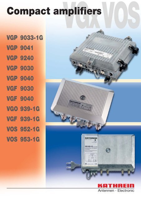
Compact amplifiers<br />
VGP 9033-<strong>1G</strong><br />
VGP 9041<br />
VGP 9240<br />
VGP 9030<br />
VGP 9040<br />
<strong>VGF</strong> 9030<br />
<strong>VGF</strong> 9040<br />
VGO <strong>939</strong>-<strong>1G</strong><br />
<strong>VGF</strong> <strong>939</strong>-<strong>1G</strong><br />
VOS 952-<strong>1G</strong><br />
VOS 953-<strong>1G</strong>
CONTENTS<br />
VGP 9033-<strong>1G</strong>/9041<br />
VGP 9030/9040/9240<br />
<strong>VGF</strong> 9030/9040<br />
Product description Page 3<br />
Details, Block diagram, Accessories Page 4-6<br />
Technical data Page 7-9<br />
VGO <strong>939</strong>-<strong>1G</strong>/<strong>VGF</strong> <strong>939</strong>-<strong>1G</strong><br />
Product description Page 10<br />
Details Page 11<br />
Block diagram, Accessories Page 12<br />
Technical data Page 13<br />
VOS 952-<strong>1G</strong>/953-<strong>1G</strong><br />
Product description Page 14<br />
Details Page 15<br />
Block diagram, Accessories Page 16<br />
Technical data Page 17-18<br />
Accessories<br />
TVM 850/H, TVM 1000 Page 19<br />
HTE 10 Page 20<br />
Splitters, Taps, Equalisers Page 21-22<br />
Connectors Page 23
VGP 9033-<strong>1G</strong>/9041<br />
VGP 9030/9040/9240<br />
<strong>VGF</strong> 9030/9040<br />
DESCRIPTION<br />
VGP 9xxx – <strong>VGF</strong> 90xx<br />
• Modern, monitorable compact amplifiers for interactive<br />
HFC networks<br />
• Innovative operational concept: Using electronic<br />
tuning elements, set using HTE 10 hand-held unit<br />
(fewer plug-in cards and attenuation pads required,<br />
repeatable device settings)<br />
• Integrated frequency-agile 2-pilot control in<br />
VGP 9xxx enables quick commissioning:<br />
- Automatic levelling in the forward path, thus no<br />
need for time-consuming manual levelling<br />
- Automatic presetting of the return path is<br />
possible<br />
• Remote configuration of all setting parameters via<br />
monitoring system (can be activated/deactivated)<br />
• High gain (up to 40 dB), variable in interstageposition<br />
• Latest GaAs-MMIC technology<br />
• Very high output levels at lowest intermodulation<br />
products, even for interstage operation<br />
• Loop-through input (only for VGP 9033-<strong>1G</strong>/9041)<br />
and output splitter can be configured<br />
• De-emphasis (inverse-equalisation) insert position<br />
• Remote feeding: 7 A per input/output,<br />
local feeding: 10 A<br />
• Insert position for monitoring transponder<br />
(HMS/DOCSIS)<br />
• Test sockets on input/output and<br />
in return path amplifier<br />
• Integrated return path amplifier, settable gain<br />
• Ingress Control Switch<br />
• Aluminium die-cast housing with<br />
PG 11 connections<br />
Additional characteristics VGP 9033-<strong>1G</strong><br />
• Frequency range 862/1000 MHz switchable in<br />
VGP 9033-<strong>1G</strong><br />
• Higher output level for operation at 1000 MHz in<br />
VGP 9033-<strong>1G</strong><br />
Additional characteristics VGP 9240<br />
• Two high-level outputs with own end stage and<br />
configurable trunk output in VGP 9240<br />
• Frequency range 600/862 MHz, adjustable in<br />
VGP 9240<br />
• Gain switchable to 30 or 40 dB operation<br />
The compact amplifiers with<br />
electronic tuning elements –<br />
VGP 9xxx and <strong>VGF</strong> 90xx<br />
With the VGP 9xxx and <strong>VGF</strong> 90xx Kathrein offers a<br />
latest-generation compact amplifier series. A wide<br />
range of settings, electronic operation and excellent<br />
technical data – at an unbeatable price/performance<br />
ratio.<br />
"Plug-and-Play" redefined<br />
Electronic setting of all important parameters,<br />
automatic levelling (only for 9xxx) as well as remote<br />
configuration via HMS or DOCSIS monitoring ensure<br />
the shortest start-up and maintenance times. The copy<br />
function enables one to copy all settings and transfer<br />
them to another device at the press of a button.<br />
The absence of plug-in cards for gain and slope<br />
not only accelerates start-up, but also simplifies logistics<br />
and saves warehousing costs.<br />
Another advantage during modifications:<br />
new values are taken over without any interruptions.<br />
Multimedia services remain undisturbed.<br />
Start-up without a measuring<br />
instrument – it doesn't get any easier<br />
than this<br />
Due to automatic levelling, the compact amplifiers<br />
VGP 9xxx can be put into operation<br />
with just a few steps:<br />
- Simply enter the desired output level for the<br />
lower and upper pilot frequency and start<br />
levelling<br />
- After a few seconds, the device automatically<br />
sets the desired values, whereby optimal<br />
technical data are continuously reached.<br />
Manual vernier adjustment is still possible at<br />
any time.<br />
- Subsequently, automatic presetting can also<br />
be effected in the return path.<br />
- For the next devices, levelling runs even more<br />
quickly. The copy function enables desired<br />
settings to be automatically incorporated.<br />
3
VGP 9033-<strong>1G</strong>/9041<br />
VGP 9030/9040/9240<br />
<strong>VGF</strong> 9030/9040<br />
Insert position "Forward 1"<br />
e.g. for additional<br />
C-line pre-emphasis<br />
Insert position for monitoring<br />
transponder<br />
(not included in delivery scope)<br />
Insert position "Forward 2"<br />
Connection socket for<br />
hand-held unit HTE 10<br />
F-type test socket<br />
internal (-20 dB)<br />
F-type test socket<br />
internal (-20 dB)<br />
Input insert position<br />
F-type broadband input for the<br />
return path with protective cap (-10 dB)<br />
Output insert position<br />
Image: VGP 9033-<strong>1G</strong>/9041<br />
Delivery status<br />
Note: The input and output plug-in positions on<br />
the VGP 9033-<strong>1G</strong>/9041 and the output plugin<br />
position on the VGx 9030/9040 must each<br />
be equipped with a EBC xx-<strong>1G</strong>/EAC xx-<strong>1G</strong> for<br />
operation. The other plug-in positions and the<br />
VGP 9240 are already equipped with null cards<br />
Input and output cable fittings not included in<br />
the delivery scope of VGP 9033-<strong>1G</strong>/9041/9240<br />
(see page 23)<br />
Accessories<br />
• EBC 01E-<strong>1G</strong> (Order no. 24510121): Null card input<br />
• EBC 00-<strong>1G</strong> (Order no. 24510119): Null card output,<br />
for operation with one output<br />
• EBC 90-<strong>1G</strong> (Order no. 24510113): Splitter<br />
(2 outputs symmetrical)<br />
• EAC 93-<strong>1G</strong> (Order no. 24510115): Tap (3/6 dB)<br />
• EAC 90-<strong>1G</strong> (Order no. 24510116): Tap (1.5/10 dB)<br />
• EAC 94-<strong>1G</strong> (Order no. 24510114): Tap (0.8/20 dB)<br />
• ERC 22 (Order no. 24510085): C-line<br />
pre-emphasis equaliser for VGx 904x<br />
• ERZ 630 (Order no. 24510108): Equaliser 630 MHz<br />
• ERZ 940 (Order no. 24510059): De-emphasis<br />
equaliser (cable simulation) 862 MHz,<br />
7 dB fixed<br />
• ERS 800 (Order no. 24510109): System equaliser<br />
862 MHz<br />
• ERD 810 (Order no. 24510110): De-emphasis<br />
equaliser switchable, 862 MHz<br />
• ERD 813 (Order no. 24510117): De-emphasis<br />
equaliser<br />
• ERD 814 (Order no. 24510120): Attenuation pad<br />
• TVM 850/H (Order no. 26210077): Monitoring<br />
transponder HMS (5-42 MHz),<br />
frequency-agile<br />
• TVM 1000 (Order no. 26210086): Monitoring<br />
transponder DOCSIS<br />
• FUN 15 (Order no. 25010017): FUN remote-feed<br />
fuse 15 A/125 V DC<br />
• HTE 10 (Order no. 25010005): Hand-held unit<br />
Details see pages 19-23<br />
4
DETAILS, ACCESSORIES, BLOCK DIAGRAM, DELIVERY STATUS<br />
Image: VGP 9033-<strong>1G</strong>/9041<br />
Switched-mode power supply<br />
2-pilot control<br />
Plug-in<br />
position<br />
universal<br />
Output<br />
Ausgang<br />
Output plug-in<br />
position<br />
TP input<br />
EAC 90-<strong>1G</strong><br />
EAC 93-<strong>1G</strong><br />
EAC 94-<strong>1G</strong><br />
EBC 90-<strong>1G</strong><br />
EBC 00-<strong>1G</strong><br />
Up to two bridger<br />
outputs<br />
HMS-DOCSIS transponder (optional)<br />
TP output<br />
Image: VGP 9240<br />
5
VGP 9033-<strong>1G</strong>/9041<br />
VGP 9030/9040/9240<br />
<strong>VGF</strong> 9030/9040<br />
BLOCK DIAGRAMS<br />
Switched-mode<br />
power supply<br />
Plug-in<br />
position<br />
universal<br />
Plug-in<br />
position<br />
universal<br />
Input<br />
Output plug-in<br />
position<br />
Output<br />
Output<br />
Plug-in<br />
module<br />
Monitoring transponder<br />
Plug-in<br />
position<br />
universal<br />
-<strong>1G</strong><br />
-<strong>1G</strong><br />
-<strong>1G</strong><br />
-<strong>1G</strong><br />
-<strong>1G</strong><br />
Image: VGP 9030/9040<br />
Switched-mode<br />
power supply<br />
ERC 22<br />
Plug-in<br />
position<br />
universal<br />
dB<br />
Input<br />
Output plug-in<br />
position<br />
Output<br />
Output<br />
Plug-in<br />
module<br />
Monitoring transponder<br />
Plug-in<br />
position<br />
universal<br />
-<strong>1G</strong><br />
-<strong>1G</strong><br />
-<strong>1G</strong><br />
-<strong>1G</strong><br />
-<strong>1G</strong><br />
6<br />
Image: <strong>VGF</strong> 9030/9040
DATA<br />
Type VGP 9030 VGP 9040 <strong>VGF</strong> 9030 <strong>VGF</strong> 9040<br />
Order no. 24410106 24410107 24410108 24410109<br />
FORWARD PATH<br />
Frequency range MHz 85-862<br />
Gain (at 862 MHz) dB 33 40 33 40<br />
Return loss dB 19-1.5 dB/oct.<br />
Frequency response at (85-862 MHz 25° C) dB ± 0.5<br />
Additional frequency response (over slope and temperature range) dB ± 0.8<br />
Max. output level according to CENELEC 1) - CTB > 60 dB dBμV 114<br />
Max. output level to CENELEC 1) - CSO > 60 dB dBμV 116<br />
Attenuation range, electronically adjustable in 0.5 dB steps dB 0-16<br />
Slope range, electronically adjustable in 0.5 dB dB 0-20<br />
Interstage pre-emphasis, electronically settable in 2.5 dB steps dB 2-9<br />
Noise figure at minimum pre-emphasis dB 6<br />
Adjustment range, sloped at 85 MHz dB ± 2 -<br />
Adjustment range, parallel dB ± 3 -<br />
Frequency range lower pilot Pu ²) MHz 85-230 -<br />
Frequency range upper pilot Po ² ) MHz 570-870 -<br />
Pilot level (PAL/CW/QAM) dBμV 83-112 -<br />
Hum modulation ratio at 7 A dB 70<br />
RETURN PATH<br />
Frequency range MHz 5-65<br />
Gain dB 30<br />
Frequency response at 25 °C dB ± 0.5<br />
Input level density (CINR = 50 dB), at 28 dB gain dBμV/Hz -9<br />
Dynamic range: CINR > 50 dB, 5-65 MHz, at 28 dB gain dB 21<br />
Dynamic range: CINR > 50 dB, 5-65 MHz, at 18 dB gain dB 26<br />
Noise figure dB 6<br />
Attenuation, switchable in 1 dB steps dB 0-30<br />
Slope, switchable in 7 steps dB 1-8<br />
ICS switch (attenuation switchable over EMS or HTE 10 hand-held unit) dB 0/6/> 45<br />
Hum modulation ratio at 7 A/> 15 MHz dB 60<br />
GENERAL<br />
Voltage supply V AC 30-72<br />
Power consumption W 23 21<br />
Max. remote feed current per connection A 7<br />
Max. remote feed current in local feeding (power passing) A 10<br />
RF connections PG 11<br />
Housing protection category IP 54<br />
Ambient temperature range °C -20 to +55<br />
Screening factor Conforms to CENELEC EN 50083-2<br />
Overvoltage protection acc. to IEC 60-2<br />
2 kV (1.2/50 μs)<br />
Dimensions (W x H x D) mm 240 × 95 × 240 3)<br />
NETWORK MANAGEMENT (optional)<br />
Monitorable/settable parameters<br />
Operational voltage; current; temperature; electronic tuning elements;<br />
pilot setting and alarm; automatic levelling of forward path; automatic presetting<br />
of return path; return path gain; ICS switch; remote inventory data<br />
1) 9 dB slope 2) Set using HTE 10 hand-held unit HTE 10 3) Width incl. hinges: 267 mm<br />
7
VGP 9033-<strong>1G</strong>/9041<br />
VGP 9030/9040/9240<br />
<strong>VGF</strong> 9030/9040<br />
Type VGP 9033-<strong>1G</strong> VGP 9041<br />
Order no. 24410103 24410054<br />
FORWARD PATH<br />
Frequency range MHz 85-1000 85-862<br />
Gain dB 33 40<br />
Return loss dB 19-1.5 dB/oct.<br />
Frequency response (at 25 °C) dB ± 0.5<br />
Max. output level according to CENELEC 1) - CTB > 60 dB dBμV 114<br />
Max. output level to CENELEC 1) - CSO > 60 dB dBμV 116<br />
Attenuation range, electronically adjustable in 0.5 dB steps 4) dB 0-15 0-16<br />
Slope range, electronically adjustable in 0.5 dB steps 4) dB 0-15 0-20<br />
Interstage attenuation, settable in 1 dB steps 0-5 -<br />
Interstage pre-emphasis, electronically settable in 2.5 dB steps dB 2.5-10 2-9<br />
Noise figure at minimum pre-emphasis dB 6.5 6<br />
Adjustment range, sloped at 85 MHz dB ± 2<br />
Adjustment range, parallel dB ± 3<br />
Frequency range lower pilot Pu ²) MHz 85-230<br />
Frequency range upper pilot Po ² ) MHz 570-870 5)<br />
Pilot level (PAL/CW/QAM) dBμV 83-112<br />
Hum modulation ratio at 7 A dB > 67 > 70<br />
RETURN PATH<br />
Frequency range MHz 5-65<br />
Gain dB 28 30<br />
Frequency response at 25 °C dB ± 0.3 ± 0.5<br />
Input level density (CINR = 50 dB), at 28 dB gain dBμV/Hz -9<br />
Dynamic range: CINR > 50 dB, 5-65 MHz, at 28 dB gain dB 21<br />
Dynamic range: CINR > 50 dB, 5-65 MHz, at 18 dB gain dB 26<br />
Noise figure dB 6<br />
Attenuation, switchable in 1 dB steps dB 0-30<br />
Slope, switchable in 7 steps dB 1-8<br />
ICS switch (attenuation switchable over EMS or HTE 10<br />
hand-held unit)<br />
dB 0/6/> 45<br />
Hum modulation ratio at 7 A/> 15 MHz dB 60<br />
GENERAL<br />
Voltage supply V AC 30-72<br />
Power consumption W 23<br />
Max. remote feed current per connection A 7<br />
Max. remote feed current in local feeding (power passing) A 10<br />
RF connections PG 11<br />
Housing protection category IP 67<br />
Ambient temperature range °C -20 to +55<br />
Screening factor Conforms to CENELEC EN 50083-2<br />
Overvoltage protection acc. to IEC 60-2<br />
2 kV (1.2/50 μs)<br />
Dimensions (W x H x D) mm 240 × 95 × 240 3)<br />
NETWORK MANAGEMENT (optional)<br />
Monitorable/settable parameters<br />
Operational voltage; current; temperature; electronic tuning elements; pilot setting and<br />
alarm; automatic levelling of forward path; automatic presetting of return path; return<br />
path gain; ICS switch; remote inventory data<br />
1) 9 dB slope 2) Set using HTE 10 hand-held unit HTE 10 3) Width incl. hinges: 267 mm 4) For VGP 9033-<strong>1G</strong> in 1 dB steps 5) As of device version Bxx for VGP 9041<br />
88
DATA<br />
Type VGP 9240<br />
Order no. 24410114<br />
FORWARD PATH 4) Line/trunk output<br />
Distribution network/<br />
distribution outputs 2)<br />
Frequency range MHz 85-606/862 85-600/862<br />
Gain (at 862 MHz) dB 32 40<br />
Return loss dB 19 -1.5 dB/oct.<br />
Frequency response at (85-862 MHz 25° C) dB ± 0.5 ± 0.75<br />
Additional frequency response over attenuation, slope and temperature dB ± 0.8 ± 0.3<br />
Gain variation (ALSC off, -10 °C ... +50 °C) dB ± 0.8<br />
Signal-to-noise ratio to CENELEC 3) - 862 MHz, CSO dB 78 70<br />
Signal-to-noise ratio to CENELEC 3) - 862 MHz, CTB dB 80 70<br />
Signal-to-noise ratio to CENELEC 3) - 606 MHz, CSO dB > 78 > 70<br />
Signal-to-noise ratio to CENELEC 3) - 606 MHz, CTB dB > 80 > 70<br />
Operating output level at 862 MHz dBμV 102.5 112<br />
Attenuation range, electronically adjustable in 0.5 dB steps dB 0-15 0-10<br />
Slope range, electronically adjustable in 0.5 dB dB 0-15 0-7<br />
Pre-emphasis, electronically adjustable in 1 dB steps dB 4-8<br />
Noise figure at minimal pre-emphasis (f > 130 MHz) dB 7 8<br />
Level range, sloped at 85 MHz dB ± 2<br />
Adjustment range, parallel dB ± 3<br />
Frequency range lower pilot Pu 4) MHz 85-230<br />
Frequency range upper pilot Po 4) MHz 550-862<br />
Pilot level (PAL/CW/QAM) dBμV 82-112<br />
Hum modulation ratio at 7 A dB 70<br />
Test sockets (directional coupler) dB -20<br />
RETURN PATH<br />
Frequency range MHz 5-65 5-65<br />
Gain dB 18 27<br />
Frequency response at 25 °C dB ± 0.3 ± 0.3<br />
Additional frequency response over attenuation, slope and temperature dB ± 0.4 ± 0.4<br />
Input level density (CINR = 50 dB), at 30 dB gain dBμV/Hz 1 -8<br />
Dynamic range: CINR > 50 dB, 5-65 MHz dB 18<br />
Attenuation, switchable in 0.5 dB steps dB 20<br />
Slope, switchable in 30 steps dB 0-12<br />
ICS switch (attenuation switchable over EMS or HTE 10 hand-held unit) dB 0/6/> 36<br />
Hum modulation ratio at 7 A/> 15 MHz dB 60<br />
GENERAL<br />
Impedance inputs, outputs and test sockets Ω 75<br />
Voltage supply V AC 33-65<br />
Power consumption (without transponder) W 37<br />
Max. remote feed current per connection A 7<br />
Max. remote feed current in local feeding (power passing) A 10<br />
RF connections PG 11<br />
Housing protection category IP 54<br />
Ambient temperature range (data-conform) °C -20 to +50<br />
Max. housing temperature °C 75<br />
Screening factor Conforms to CENELEC EN 50083-2<br />
Overvoltage protection acc. to IEC 60-2<br />
2 kV (1.2/50 μs)<br />
Dimensions (W x H x D) mm 240 × 95 × 240 5)<br />
NETWORK MANAGEMENT (optional)<br />
Monitorable/settable parameters<br />
Operational voltage; current; temperature; electronic tuning elements; pilot<br />
setting and alarm; automatic levelling of forward path; automatic presetting of<br />
return path; return path gain; ICS switch; remote inventory data<br />
1) All trunk attenuation/slope settings in the forward path are also valid for the distribution network outputs. The values listed in the table can be additionally set for the distribution network outputs.<br />
2) All data refer to operation with one distribution network output 3) 862 MHz: 6 dB slope, 41 carriers without Ch2; 606 MHz: 6 dB slope, 29 carriers without Ch2 each at operational level<br />
4) Adjustable using hand-held unit HTE 10 5) Width including hinges: 267 mm<br />
9
VGO <strong>939</strong>-<strong>1G</strong>/<br />
<strong>VGF</strong> <strong>939</strong>-<strong>1G</strong><br />
DESCRIPTION<br />
VGO <strong>939</strong>-<strong>1G</strong>/<strong>VGF</strong> <strong>939</strong>-<strong>1G</strong><br />
• Latest GaAs-MMIC technology<br />
• Innovative operational concept:<br />
- Settings via slide switches<br />
- Device settings can be reproduced exactly<br />
- Fewer plug-in cards and variable attenuators<br />
needed<br />
• Integrated diplexers allow optimised data<br />
• Very high output level at lowest intermodulation<br />
products (also for interstage attenuation)<br />
• Pluggable loop-through output<br />
• One or two output(s) configurable<br />
• Built-in active return path with various setting<br />
possibilities<br />
• Return path can also be operated passively<br />
• 15 MHz high pass can be activated in the return<br />
path<br />
• Ingress Control Switch (ICS)<br />
• Monitorable with HMS or DOCSIS transponder<br />
(option)<br />
• Insert position for additional functions in the forward<br />
path (e.g. de-emphasis)<br />
• Bi-directional test socket on the amplifier input<br />
• Directional coupler test socket on amplifier output<br />
and in return path<br />
• Test signals can be coupled in for the return path<br />
• LED as function indicator<br />
• Highly efficient switched-mode power supply unit<br />
• Advanced remote power concept in the <strong>VGF</strong> <strong>939</strong>-<strong>1G</strong>:<br />
- Newly developed remote feed coils<br />
- Remote feed current: Max. 7 A per connection,<br />
local insertion max. 10 A totally<br />
- Remote feeding possibilities: By choice via all<br />
RF connections or local connector<br />
(power passing)<br />
• Surge absorbers on all RF connections and in<br />
switched-mode power supply unit<br />
• Power management: Unused amplifier stage<br />
switch-off for reduced power consumption<br />
• Die-cast housing with PG 11 connectors<br />
• Easy connection of large cable fittings due to<br />
extended thread distance<br />
• Outdoor operation possible, housing protection<br />
class: IP 54<br />
• Test sockets: F-type connectors (internal)<br />
The compact amplifiers with<br />
slide switches –<br />
VGO <strong>939</strong>-<strong>1G</strong>/<strong>VGF</strong> <strong>939</strong>-<strong>1G</strong><br />
In addition to the devices with electronic setting,<br />
Kathrein offers yet another highly innovative compact<br />
amplifier platform. This particularly economical series<br />
requires no equaliser cards or attenuation pads.<br />
All adjustments can be easily carried out using slide<br />
switches.<br />
Simple, yet effective<br />
The required attenuation and slope values are set with<br />
a combination of several slide switches. The advantages<br />
are obvious. Besides savingplug-in cards, this<br />
allows exact reproduction of setting values without<br />
requiring a measuring instrument. Replacement of the<br />
device, for example, is thus much easier.<br />
When slide switches are shifted, a virtually uninterrupted<br />
signal flow is guaranteed – multimedia services<br />
remain undisturbed.<br />
Maximum reliability<br />
The implemented slide switches fulfil the highest<br />
demands regarding reliability and endurance. Dual<br />
gold-plated contact reeds, increased contact pressure<br />
and a separate catch spring ensure ultimate reliability<br />
of the switches, which have been proven and tested<br />
100,000 times.<br />
10
DETAILS<br />
Input insert position e.g. for<br />
de-emphasis equaliser<br />
Insert position for monitoring transponder<br />
(not included in delivery scope)<br />
LED (Power supply<br />
function)n)<br />
Forward path:<br />
Adjustment of attenuation<br />
and equalisation using<br />
slide switches<br />
Direct supply to<br />
device up to<br />
10 A<br />
Splitter field<br />
loop-through input<br />
F-type<br />
test socket<br />
for the<br />
return path<br />
(-10 dB)<br />
Output<br />
splitter field<br />
F-type test socket<br />
on output for return<br />
path measurement<br />
or feed-in (-20 dB)<br />
F-type test<br />
socket<br />
bidirectional on<br />
input (-20 dB)<br />
Return path<br />
switchable<br />
passive/active<br />
Integrated return path<br />
amplifier, adjustable<br />
with slide switches<br />
11
VGO <strong>939</strong>-<strong>1G</strong>/<br />
<strong>VGF</strong> <strong>939</strong>-<strong>1G</strong><br />
ACCESSORIES<br />
BLOCK DIAGRAM<br />
DELIVERY STATUS<br />
Option<br />
De-emphasis<br />
0 / 10 dB<br />
2 / 0 / 4 dB 6 / 0 / 12 dB 2 / 0 / 4 dB 6 / 0 / 12 dB<br />
4 / 0 / 8 dB<br />
Interstage<br />
1 / 0 / 2 dB 3 / 0 / 6 dB<br />
dB<br />
dB<br />
dB<br />
dB<br />
Attenuation<br />
or<br />
pre-emphasis<br />
Pre-emphasis<br />
Attenuation<br />
Monitoring transponder<br />
Pre-emphasis<br />
Attenuation<br />
Attenuation<br />
-20 dB<br />
85 - 1006 MHz<br />
5 - 65 MHz<br />
Current<br />
Temperature<br />
Ub<br />
ICS<br />
Option<br />
85 - 1006 MHz<br />
5 - 65 MHz<br />
passive<br />
active<br />
Internal<br />
Test 1<br />
-20 dB<br />
bi-directional<br />
Loop through<br />
splitter field<br />
v = 14 dB<br />
Option<br />
3 / 0 / 6 dB<br />
Pre-emphasis<br />
5-65 MHz<br />
2 / 0 / 4 dB<br />
dB<br />
Attenuation<br />
6 / 0 / 12 dB<br />
dB<br />
30 dB<br />
21 dB<br />
Switched-off<br />
C<br />
Internal<br />
Test 3<br />
-10 dB<br />
max. 7 A<br />
power passing: 10 A<br />
32-72 V AC<br />
(P<br />
nominal<br />
= 60 dBμV)<br />
SNT<br />
-30 dB<br />
0 / -8 dB /<br />
"switched-off"<br />
Ingress<br />
detection<br />
5 MHz<br />
15 MHz<br />
Option<br />
4 / 0 / 8 dB<br />
dB<br />
Attenuation<br />
Output<br />
splitter field<br />
(Return path:<br />
P = 70 dBμV)<br />
nominal<br />
Internal<br />
Test 2<br />
-20 dB<br />
S10<br />
Return path<br />
measurement<br />
or feed-in<br />
15 A T3,15AL<br />
A<br />
B<br />
D<br />
E<br />
Input<br />
PG11<br />
Loop through<br />
PG11<br />
= slide switches<br />
A/B/E/D = 15-A fuse<br />
Output 2<br />
PG11<br />
Output 1<br />
PG11<br />
Delivery status<br />
• For operation with one input or output, no plug-in<br />
cards required<br />
• All insert positions are fitted with 0-dB bridging<br />
plugs ex works<br />
• Input and output cable fittings not included in the<br />
delivery scope (see page 23)<br />
Accessories<br />
• EBC 90-<strong>1G</strong> (Order no. 24510113):<br />
Splitter (2 outputs symmetrical)<br />
• EAC 93-<strong>1G</strong> (Order no. 24510115):<br />
Tap (3/6 dB)<br />
• EAC 90-<strong>1G</strong> (Order no. 24510116):<br />
Tap (1.5/10 dB)<br />
• EAC 94-<strong>1G</strong> (Order no. 24510114):<br />
Tap (0.8/20 dB)<br />
• ERZ 940 (Order no. 24510059):<br />
De-emphasis equaliser<br />
(cable simulation) 862 MHz,<br />
7 dB fixed<br />
• ERD 810 (Order no. 24510110):<br />
De-emphasis equaliser<br />
• ERD 813 (Order no. 24510117):<br />
De-emphasis equaliser<br />
• ERD 814 (Order no. 24510120):<br />
Attenuation pad<br />
• ERZ 630 (Order no. 24510108):<br />
Equaliser 47-630 MHz, switchable<br />
2-18 dB in 2 dB steps<br />
• ERS 800 (Order no. 24510109):<br />
System equaliser 862 MHz<br />
• TVM 850/H (Order no. 26210077):<br />
Monitoring transponder HMS<br />
(5-42 MHz), frequency-agile<br />
• TVM 1000 (Order no. 26210086):<br />
Monitoring transponder DOCSIS<br />
12
DATA<br />
Type VGO <strong>939</strong>-<strong>1G</strong> <strong>VGF</strong> <strong>939</strong>-<strong>1G</strong> Remarks<br />
Order no. 24410101 24410100<br />
FORWARD PATH<br />
Locally fed<br />
Remotely fed<br />
Frequency range MHz 85-1006<br />
Gain dB 40<br />
Gain setting range, interstage ³ ) dB 32-40<br />
Amplitude response dB ±0.5 85-1006 MHz, at 25 °C<br />
Amplitude response (additional, from 862-1006 MHz) dB -0.5 at 25°C<br />
Attenuation setting range, on input 3) dB 0-26<br />
Pre-emphasis setting range, at input ³ ) or interstage dB 0-26 or 0/4/8<br />
Return loss, as of 40 MHz dB 18-1.5/oct.<br />
Noise figure dB 4 at 40 dB gain<br />
Max. operational level: CENELEC raster ¹) dBμV 116/118 CTB: 60 dB/CSO: 60 dB (pre-emphasis 4 dB)<br />
Hum modulation ratio dB - 60/70 AT 7 A, 5-65/85-1006 MHz<br />
RETURN PATH<br />
Frequency range MHz 5-65<br />
Gain (input stage bridged), active operation dB 30 (21)<br />
Gain, passive operation dB -2<br />
Amplitude response dB 0.5<br />
Attenuation setting range, at input or interstage ³ ) dB 0/4/8 or 0-16<br />
Pre-emphasis setting range, interstage dB 0/3/6<br />
Ingress Control Switch (ICS) dB 8/> 40 attenuated/switched-off<br />
Max. output level at 30 and 21 dB gain dBμV 107/116 60 dB IMod2/IMod3 (EN 60728-3/50083-5)<br />
Max. output level dBμV 120<br />
According to KDG 1 TS 140<br />
(full system load)<br />
Input level density dBμV/Hz -8 CINR at 50 dB (EN 60728-3/item 4.7)<br />
Dynamic range at 30 dB gain (5-65 MHz) ² ) dB 18<br />
Dynamic range at 21 dB gain (5-65 MHz) ² ) dB 25<br />
Noise figure dB 5<br />
NETWORK MANAGEMENT<br />
Monitorable parameters<br />
Internal voltage supply, internal current drain,<br />
internal temperature, ICS switch<br />
TEST SOCKETS<br />
Test socket 1 (on amplifier input), bi-directional dB 20<br />
Test socket 2 (on amplifier output), directional coupler dB 20<br />
Possibility to feed in return path signals<br />
(5-65 MHz); if button is kept pressed, the incoming<br />
return path signal can be measured<br />
Test socket 3 (in return path amplifier), directional coupler dB 10 Attenuation relative to return path input<br />
SWITCHED-MODE POWER SUPPLY<br />
Input voltage range V AC 230 32-72<br />
Mains frequency range Hz 50-60<br />
Max. remote feed current A - 7 per input or output<br />
Max. remote feed current, local insertion A - 10<br />
Power consumption (without monitoring) W 17.5 Return path amplifier active<br />
GENERAL<br />
Classification according to KDG 1 TS 140<br />
D(4.4)<br />
Ambient temperature range °C -20 to +55 data-conform operation<br />
RF connections PG 11<br />
Test sockets<br />
F-type connector<br />
Housing protection class (to EN 60529) IP 54<br />
Dimensions (W x H x D) mm 238 × 86 × 189<br />
Packing unit/weight pc./kg 1(10)/2.2<br />
1) CENELEC: 41 channels 2) When the 15 MHz high pass is connected, the dynamic range increases by 3 dB ³ ) Settable in 2-dB steps using slide switches<br />
13
VOS 952-<strong>1G</strong>/953-<strong>1G</strong><br />
DESCRIPTION<br />
VOS 952-<strong>1G</strong>/953-<strong>1G</strong><br />
• Latest GaAs-MMIC technology<br />
• Innovative operational concept:<br />
- Settings via slide switches<br />
- Device settings can be reproduced exactly<br />
- Fewer plug-in cards and variable attenuators<br />
needed<br />
• Very high output level at lowest intermodulation<br />
products<br />
• Built-in active return path with various setting<br />
possibilities<br />
• 15 MHz high pass can be activated in the return<br />
path<br />
• Ingress Control Switch (ICS)<br />
• Monitorable with HMS or DOCSIS (option)<br />
• Insert position for additional functions in the<br />
forward path (e.g. de-emphasis)<br />
• Bi-directional test socket on amplifier input with<br />
inductive coupling<br />
• Directional coupler test socket on amplifier output<br />
and in return path<br />
• Test signals can be coupled in for the return path<br />
• Highly efficient switched-mode power supply unit<br />
• VOS 952-<strong>1G</strong> - locally fed, F-type connectors<br />
• VOS 953-<strong>1G</strong> - remotely fed (auto-supply),<br />
F-type sockets<br />
• Surge absorbers on all RF connections and in<br />
switched-mode power supply unit<br />
• Die-cast housing<br />
• Test sockets: F-type sockets<br />
House connection amplifiers<br />
The compact, price-optimised house connection<br />
amplifiers 952-<strong>1G</strong> and VOS 953-<strong>1G</strong> were designed<br />
for application in modern HFC networks. Great value<br />
was set upon a high dynamic range for Interstage<br />
tage<br />
operation as well as upon a cost-efficient operation<br />
on<br />
concept with slide switches.<br />
Monitoring via DOCSIS transponder<br />
If fitted with the optional monitoring transponder<br />
nder<br />
TVM 1000, the amplifiers VOS 952-<strong>1G</strong>/953-<strong>1G</strong> 9 1 can<br />
be monitored via DOCSIS protocol.<br />
Monitoring with HMS<br />
Both amplifiers can be flexibly integrated into<br />
monitoring systems which operate with the<br />
widespread HMS protocol.<br />
Bridgeable diplex filter<br />
Bridging plugs enable variation of the frequency<br />
en<br />
range between 47-1006 MHz and 85-1006 MHz<br />
making it possible to carry out transmission si<br />
in<br />
Band I in the forward path (without return rn path).<br />
Flexible return path<br />
In the latest generation, the return path can<br />
be<br />
operated either actively or passively.<br />
14
DETAILS<br />
Input insert position<br />
e.g. for de-emphasis equaliser<br />
Insert position for<br />
monitoring transponder<br />
(not included in delivery scope)<br />
LED<br />
(Power supply function)<br />
on)<br />
Forward path:<br />
Adjustment of<br />
attenuation and<br />
equalisation using<br />
slide switches<br />
F-type test socket bidirectional on input (-20 dB)<br />
Return path<br />
switchable<br />
passive/active<br />
F-type test socket<br />
on output for return<br />
path measurement<br />
or feed-in (-20 dB)<br />
F-type test socket for the return path (-10 dB)<br />
Integrated return path<br />
amplifier, adjustable<br />
with slide switches<br />
15
VOS 952-<strong>1G</strong>/953-<strong>1G</strong><br />
ACCESSORIES<br />
BLOCK DIAGRAM<br />
DELIVERY STATUS<br />
85-1006 MHz 47-1006 MHz<br />
85-1006 MHz 47-1006 MHz<br />
85-1006 MHz<br />
85-1006 MHz<br />
Delivery status<br />
• The insert position is fitted with a 0-dB<br />
bridging plug ex works<br />
16<br />
Accessories<br />
ERZ 940 (Order no. 24510059):<br />
De-emphasis equaliser<br />
(cable simulation) 862 MHz,<br />
7 dB fixed<br />
ERZ 630 (Order no. 24510108):<br />
Equaliser 47-630 MHz,<br />
switchable 2-18 dB in 2 dB steps<br />
ERS 800 (Order no. 24510109):<br />
System equaliser 862 MHz<br />
ERD 810 (Order no. 24510110):<br />
De-emphasis equaliser,<br />
switchable 3 dB<br />
TVM 850/H (Order no. 26210077):<br />
Monitoring transponder HMS<br />
(frequency-agile)<br />
TVM 1000 (Order no. 26210086):<br />
Monitoring transponder DOCSIS
DATA<br />
Type VOS 952-<strong>1G</strong> VOS 953-<strong>1G</strong> Remarks<br />
Order no. 24410098 24410099<br />
Locally fed<br />
Remotely fed<br />
FORWARD PATH<br />
Frequency range MHz 47/85-1006<br />
Gain 1) dB 40-32 Interstage gain setting<br />
Amplitude response dB ± 0.5 85-1006 MHz, at 25 °C<br />
Amplitude response<br />
(additional, from 862-1006 MHz)<br />
dB - 0.5 at 25 °C<br />
Attenuation setting range dB 0-16 On amplifier input<br />
Pre-emphasis setting range dB 0-16 and 0/6 On amplifier input and interstage<br />
Noise figure dB 4/5/5 At 40/36/32 dB gain<br />
Max. operational level: CENELEC raster 2) dBμV 112/116<br />
CTB: 60 dB/CSO: 60 dB<br />
(pre-emphasis 6 dB and gain<br />
39.5 dB)<br />
Hum modulation ratio dB - > 60/70<br />
Return path<br />
Frequency range MHz 5-65<br />
Gain, switchable dB 30/21<br />
Frequency response dB 0.5<br />
Attenuation setting range dB 0-16 / 0/4/8 On input/interstage<br />
Pre-emphasis setting range dB 0/3/6 Interstage<br />
Ingress Control Switch (ICS) dB 8/> 40 attenuated/switched-off<br />
Max. output level at 30 and 21 dB gain dBμV 107/116<br />
Maximum output level dBμV 120<br />
Input level density dBμV/Hz -10<br />
Dynamic range (5-65 MHz) ³ ) dB 17<br />
Dynamic range (5-65 MHz) ³ ) dB 25<br />
Noise figure dB 5<br />
NETWORK MANAGEMENT<br />
Monitorable parameters<br />
TEST SOCKETS<br />
Internal supply voltage, internal current drain,<br />
temperature, ICS switch<br />
Test socket 1 (on amplifier input) dB 20<br />
Test socket 2 (on amplifier output) dB 20<br />
Test socket 3 (in return path) dB 10<br />
60 dB IM2/IM3<br />
(EN 60728-3/50083-5)<br />
According to KDG 1 TS 140 (full<br />
system load)<br />
CINR at 50 dB<br />
(EN 60728-3/item 4.7)<br />
5-1,006 MHz bi-directional,<br />
internal<br />
5-1,006 MHz with directional<br />
coupler, external - return path<br />
signals can be fed in (5-65 MHz);<br />
if push-button is kept pressed,<br />
the incoming return path signal<br />
can be measured<br />
5-65 MHz with directional<br />
coupler, external<br />
17
VOS 952-<strong>1G</strong>/953-<strong>1G</strong><br />
DATA<br />
Type VOS 952-<strong>1G</strong> VOS 953-<strong>1G</strong> Remarks<br />
Order no. 24410098 24410099<br />
Locally fed<br />
Remotely fed<br />
SWITCHED-MODE POWER SUPPLY<br />
Nominal input voltage V AC 110-230 38-65<br />
Mains frequency range Hz 50-60<br />
Power consumption W 11 12<br />
GENERAL<br />
Ambient temperature range °C -20 to +55<br />
RF connections F-type socket<br />
Test sockets F-type socket<br />
Housing protection class (to EN 60529) IP 54<br />
Dimensions (W x H x D) mm 225 × 55 × 155<br />
Packing unit/weight pc./kg 1(10)/1.8<br />
Return path amplifier active/<br />
without monitoring<br />
IP 54: Outdoor use in<br />
weather-proof cabinet<br />
¹) Adjustable with 2 slide switches in 1 dB steps<br />
² ) CENELEC: 42 channels<br />
³ ) When the 15 MHz high pass is connected, the dynamic range increases by 3 dB<br />
18
ACCESSORIES<br />
Monitoring transponder HMS protocol,<br />
frequency-agile<br />
• Monitoring transponder for compact amplifiers, house<br />
connection amplifiers and optical compact receivers<br />
(see table)<br />
• Monitors various parameters such as voltage,<br />
current drain and internal temperature<br />
• Controls the Ingress Control switch in correspondingly<br />
equipped devices<br />
• Transmission in the HMS protocol<br />
• Frequency-agile in range 5-42 MHz<br />
Type TVM 850/H<br />
Order no. 26210077<br />
Input frequency range MHz 75-90.5<br />
Input level range dBμV 50-95<br />
Output frequency range MHz 5-42<br />
Max. output level dBμV 105<br />
Power consumption W 1<br />
Transmission protocol<br />
HMS<br />
Suitable for<br />
VGO <strong>939</strong>, <strong>VGF</strong> <strong>939</strong>, VGO <strong>939</strong>-<strong>1G</strong>, <strong>VGF</strong> <strong>939</strong>-<strong>1G</strong>, VOS 952/953, VOS 952-<strong>1G</strong>,<br />
VOS 953-<strong>1G</strong>, ORA 9022, ORA 9022-<strong>1G</strong>, ORA 920/921, VGP 9033,<br />
VGP 9033-<strong>1G</strong>, VGP 9041, <strong>VGF</strong> 9030/9040<br />
TVM 1000 - Monitoring transponder<br />
DOCSIS/EuroDOCSIS, frequency-agile<br />
• Monitoring transponder for compact/house connection amplifiers<br />
and optical compact receivers (see table)<br />
• Monitors various parameters such as voltage, current drain<br />
and internal temperature<br />
• Controls the Ingress Control switch in correspondingly equipped<br />
devices<br />
• Transmission in DOCSIS or EuroDOCSIS protocol<br />
• Frequency-agile in range 5-65 MHz and 90-862 MHz<br />
Type TVM 1000<br />
Order no. 26210086<br />
Input frequency range MHz 90-862<br />
Input level range dBμV 48-78<br />
Output frequency range MHz 5-65<br />
Max. output level dBμV 113-118<br />
Power consumption W 3.5<br />
Transmission protocol DOCSIS/EuroDOCSIS 2.0<br />
Suitable for<br />
VGO <strong>939</strong>, VGO <strong>939</strong>-<strong>1G</strong>, <strong>VGF</strong> <strong>939</strong>, <strong>VGF</strong> <strong>939</strong>-<strong>1G</strong>, VOS 952/953, VOS 952-<strong>1G</strong>,<br />
VOS 953-<strong>1G</strong>, ORA 9022, ORA 9022-<strong>1G</strong>, ORA 920/921, VGP 9033 as of version<br />
A03 (Nov. 2008), VGP 9033-<strong>1G</strong>, VGP 9041 as of version A02 (Nov. 2008),<br />
<strong>VGF</strong> 9030/9040<br />
19
ACCESSORIES<br />
HTE 10 - Hand-held unit<br />
With the HTE 10 hand-held unit one is able to adjust<br />
correspondingly equipped devices on site. Using the<br />
'Up' and 'Down', 'Menu' and 'Enter' buttons, one is able<br />
to change and set the values on the 4-line display. The<br />
display is illuminated and easy to read.<br />
The hand-held unit presents<br />
the following functions:<br />
• All appropriately equipped devices or modules can be<br />
adjusted and operated<br />
• All settings are displayed<br />
• The last settings are saved (copy function)<br />
• The hand-held unit is power-supplied by the<br />
respective module<br />
• Distances:<br />
- Data transfer between HTE 10 and the device or<br />
module over max. 14 m<br />
- Standard connection cable: 2 m<br />
(included in delivery scope)<br />
- Can be extended to 14 m (TDK 10)<br />
• 4-line display, illuminated<br />
• Language: English<br />
• Splash-proof/shock-proof<br />
• Ambient conditions:<br />
- Ambient temperature: -20 to +50 °C<br />
- Suitable for outdoor application<br />
- Protection category: IP 54<br />
• Control signal: Serial, RS 232<br />
• Connection: Sub D, 9-pin<br />
• Accessories (not included in delivery scope):<br />
TDK 10 - Order no. 26210054: Connection cable 14 m<br />
TDK 12 - Order no. 26210076: PC connection cable for<br />
HTE 10 (for software updates)<br />
20
ACCESSORIES<br />
EAC 90-<strong>1G</strong>, 93-<strong>1G</strong>, 94-<strong>1G</strong> - Taps<br />
• Plug-in modules to extend the corresponding devices to<br />
two outputs<br />
• When inserted in the amplifier's input section these<br />
modules can be used to configure a loop-through input<br />
EBC 00-<strong>1G</strong> und EBC 01E-<strong>1G</strong> – Null cards<br />
(output, input)<br />
• Plug-in modules for operation of the VGP 90xx<br />
distribution network amplifiers with one input or output<br />
• EBC 01E-<strong>1G</strong>: For operation on the input insert position<br />
• EBC 00-<strong>1G</strong>: For operation on the output insert position<br />
EBC 90-<strong>1G</strong> – Splitter, 2-way<br />
Type EBC 01E-<strong>1G</strong> EBC 00-<strong>1G</strong><br />
Order no. 24510121 24510119<br />
Frequency range MHz 5-1000 5-1000<br />
Through loss ¹ ) dB < 0.5 < 0.5<br />
Type<br />
EAC<br />
90-<strong>1G</strong><br />
EAC<br />
93-<strong>1G</strong><br />
EAC<br />
94-<strong>1G</strong><br />
EBC<br />
90-<strong>1G</strong><br />
1) The through loss is the signal loss between the unit's output and output 1<br />
when the insert is inserted in the output section insertion point or between<br />
the unit‘s input and the tap output when the insert is inserted in the unit's<br />
input section (input configuration section)<br />
Order no. 24510116 24510115 24510114 24510113<br />
Frequency range MHz 5-1000 5-1000 5-1000 5-1000<br />
Through loss ¹ )<br />
5-610 MHz<br />
dB < 1.3 < 2.1 < 0.5 < 3.6<br />
Through loss ¹ )<br />
610-862 MHz<br />
dB < 1.3 < 2.3 < 0.6 < 3.8<br />
Through loss ¹ )<br />
862-1000 MHz<br />
< 1.5 < 2.6 < 0.9 < 3.9<br />
Tap loss dB 10 6 20<br />
Like<br />
through<br />
loss<br />
ERC 22 - C-line pre-emphasis equaliser<br />
• Generates pre-emphasis based on the C-line<br />
specifications of Kabel Deutschland<br />
• For use in the amplifiers VGP 9041/<strong>VGF</strong> 9040<br />
• Application in the universal input insert position ("Forward 1")<br />
Decoupling 5-65 MHz dB > 28 > 23 > 38 > 28<br />
Decoupling as of<br />
65-610 MHz<br />
Decoupling as of<br />
610-862 MHz<br />
Decoupling as of<br />
862-1000 MHz<br />
dB > 26 > 23 > 33 > 22<br />
> 24 > 23 > 30 > 20<br />
> 22 > 20 > 28 > 18<br />
Type ERC 22<br />
Order no. 24510085<br />
1) The through loss is the signal loss between the unit's output and output 1<br />
when the insert is inserted in the output section insertion point or between<br />
the unit's input and the tap output when the insert is inserted in the unit's<br />
input configuration section<br />
Transmission range MHz 50-862<br />
Nominal impedance Ω 75<br />
Pre-emphasis<br />
For C-lines<br />
Basic loss (at 862 MHz) dB 1<br />
Return loss dB 23 -1/oct.<br />
21
Accessories<br />
ACCESSORIES<br />
ERZ 940 – De-emphasis equaliser<br />
ERS 800 – System equaliser<br />
• Cable analogue 7 dB<br />
• System equaliser for use in special applications<br />
• Characteristics:<br />
- Cable-equivalent pre-emphasis 47-700 MHz: 3 dB<br />
(at 47-862 MHz: 4 dB)<br />
- Cable-equivalent pre-emphasis 700-862 MHz: 3 dB<br />
(equivalent to additional emphasis by 2 dB in 700-862 MHz)<br />
Type ERZ 940<br />
Order no. 24510059<br />
Transmission range MHz 47-862<br />
Nominal impedance Ω 75<br />
De-emphasis dB 7 ± 1<br />
Basic loss (at 47 MHz) dB 0.3<br />
Return loss dB 20-3<br />
Principal frequency response curve ERS 800<br />
MHz<br />
0 47 100 200 300 400 500 600 700 800 862<br />
0<br />
1<br />
2<br />
3<br />
dB<br />
4<br />
5<br />
6<br />
7<br />
ERZ 630 – Equaliser<br />
• Equaliser 47-630 MHz<br />
• Switchable in 2-dB steps<br />
from 2-18 dB<br />
(cable equivalent)<br />
Type ERZ 630<br />
Type ERS 800<br />
Order no. 24510109<br />
Transmission range MHz 47-862<br />
Nominal impedance Ω 75<br />
Cable-equivalent pre-emphasis,<br />
47-700/(equivalent to 47-862) MHz<br />
dB 3/(4)<br />
Cable-equivalent pre-emphasis<br />
in the range 700-862 MHz<br />
dB 3<br />
Basic loss (at 862 MHz) dB 0.5<br />
Return loss dB > 15<br />
Order no. 24510108<br />
Transmission range MHz 47-630<br />
Nominal impedance Ω 75<br />
Basic loss (at 47/630 MHz) dB 0.5/1.5<br />
Equalisation,<br />
adjustable in 2-dB steps<br />
dB 2-18<br />
22
ACCESSORIES<br />
Remote-feed fuse<br />
De-emphasis equaliser/attenuator<br />
ERD 810<br />
ERD 813<br />
ERD 814<br />
• Cable simulation switchable:<br />
- Cable-equivalent<br />
Switchable 3, 6 and<br />
- KDG de-emphasis<br />
Switchable 0, 4 and<br />
• Both de-emphases<br />
• Available types:<br />
- ERD 810: De-emphasis<br />
- ERD 813: Cable-equivalent<br />
- ERD 814: 6 dB attenuation<br />
¹) In reference to 85-862 MHz<br />
FUN 15<br />
25010017<br />
• 15 A/125 V DC<br />
PG 11 connectors<br />
EMP 26 275281<br />
EMP 28 275283<br />
EMP 29 275284<br />
EMP 34 275289<br />
EMP 35 2753000<br />
de-emphasis 85-862862 MHz:<br />
9 dB<br />
470-862 MHz:<br />
8 dB<br />
can be used in combination<br />
equaliser, switchable, 862 MHz<br />
de-emphasis 6 dB ¹)<br />
¹)<br />
EMU 29 2732433<br />
Type ERD 810 ERD 813 ERD 814<br />
EMP 26<br />
Order no. 24510110 24510117 24510120<br />
Transmission range MHz 85-862 85-1000<br />
Nominal impedance Ω 75<br />
Attenuation (linear) dB - 1 6<br />
Return loss dB - 20 -1.5/octave<br />
De-emphasis dB 3 7 -<br />
KDG de-emphasis<br />
470-862 MHz:<br />
dB 0/4/8 - -<br />
switchable<br />
Cable equivalent<br />
de-emphasis<br />
dB 3/6/9 - -<br />
85-862 MHz, switchable<br />
Basic attenuation<br />
(at 85 MHz)<br />
dB 0.5 - -<br />
• Plugs<br />
EMP 26: Plug for cables<br />
LCD 90/95/99/110/111/115<br />
EMP 28: Plug for LCM 14/17 cables<br />
• Cable fittings<br />
EMP 29: Cable fitting for LCM 33 cable<br />
• Adapters: PG 11 to IEC socket with<br />
M14 external thread<br />
EMP 35: PG 11 to F-type socket (female)<br />
EMU 29: PG 11 adapter ring to 5/8"<br />
F-type cable fittings<br />
EMK 104 273195<br />
EMK 105 273196<br />
EMK 106 273197<br />
EMK 106<br />
• F-type cable fittings<br />
EMK 104: F-type cable fitting for LCM 33 cable<br />
EMK 105: F-type cable fitting for LCM 50 cable<br />
EMK 106: F-type cable fitting for LCM 96 cable<br />
23
The products described must only be installed by<br />
qualified specialists. Please consult the provided<br />
instruction manuals for the safety instructions that<br />
are to be considered during use.<br />
We would be pleased to advise you:<br />
99811672/1/0410/JH/Pf Technical data subject to modification. Technical data represent typical values.<br />
www.kathrein.de · catv@kathrein.de<br />
KATHREIN-Werke KG · Phone +49 (0)8031 184-0 · Fax +49 (0)8031 184-385<br />
Anton-Kathrein-Str. 1 - 3 · P.O. Box 10 04 44 · 83004 Rosenheim · GERMANY