Install the gear lash pedestal, J 35596-15, into the threaded ... - ddcsn
Install the gear lash pedestal, J 35596-15, into the threaded ... - ddcsn
Install the gear lash pedestal, J 35596-15, into the threaded ... - ddcsn

Create successful ePaper yourself
Turn your PDF publications into a flip-book with our unique Google optimized e-Paper software.
SERIES 60 SERVICE MANUAL<br />
[a]<br />
[b]<br />
<strong>Install</strong> <strong>the</strong> <strong>gear</strong> <strong>lash</strong> <strong>pedestal</strong>, J <strong>35596</strong>-<strong>15</strong>, <strong>into</strong> <strong>the</strong> <strong>threaded</strong> hole of <strong>the</strong> camshaft<br />
drive <strong>gear</strong>. See Figure 1-331. Bar <strong>the</strong> engine over until <strong>the</strong> tool is at <strong>the</strong> three<br />
o’clock position.<br />
For Series 60 engines equipped with <strong>the</strong> compact <strong>gear</strong> train use <strong>the</strong> following<br />
procedure: <strong>Install</strong> <strong>the</strong> <strong>gear</strong> <strong>lash</strong> <strong>pedestal</strong> J-46303 onto <strong>the</strong> center of <strong>the</strong> camshaft <strong>gear</strong>.<br />
See Figure 1-331a. Adjust it so <strong>the</strong> dial indicator is positioned at a 90 angle to <strong>the</strong><br />
measuring bar and is at <strong>the</strong> scribe line on <strong>the</strong> bar.<br />
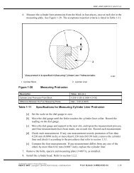
1. Gear Lash Adjustment Tool 4. Dial Indicator<br />
2. Adjustable Idler Gear Retaining Nut 5. Pedistal Idler Gear Hole<br />
3. Magnetic Base 6. Adjustable Idler Gear Retaining Nut<br />
Figure 1-331<br />
Camshaft Drive Gear-to-Adjustable Idler Gear Lash Measurement<br />
NOTE:<br />
Since <strong>the</strong> teeth of <strong>the</strong> camshaft drive <strong>gear</strong> are not accessible with <strong>the</strong> <strong>gear</strong> case cover<br />
installed, <strong>the</strong> <strong>lash</strong> is measured on <strong>the</strong> <strong>pedestal</strong> installed in <strong>the</strong> <strong>threaded</strong> hole, which is<br />
located exactly half-way between <strong>the</strong> center and edge of <strong>the</strong> camshaft drive <strong>gear</strong>. For<br />
this reason, <strong>the</strong> reading obtained will be exactly 1/2 of <strong>the</strong> actual <strong>gear</strong> <strong>lash</strong>.<br />
NOTE:<br />
For Series 60 engines equipped with <strong>the</strong> Compact Gear Train Assembly, <strong>the</strong> <strong>gear</strong> <strong>lash</strong><br />
measuring adaptor has a predetermined spot where <strong>the</strong> <strong>lash</strong> measurement must be<br />
taken. The measurement bar must be installed <strong>into</strong> <strong>the</strong> magnetic base correctly and <strong>the</strong><br />
dial indicator positioned between <strong>the</strong> marks at <strong>the</strong> end of <strong>the</strong> bar.<br />
[c] Mount a dial indicator adaptor and dial indicator. See Figure 1-331.<br />
All information subject to change without notice. (Rev. 06/03)<br />
6SE483 0303 Copyright © 2003 DETROIT DIESEL CORPORATION From Bulletin 5-60-03 1-407
1.21 GEAR TRAIN AND ENGINE TIMING<br />
[d]<br />
[e]<br />
[f]<br />
[g]<br />
For Series 60 engines equipped with <strong>the</strong> Compact Grear Train Assembly, mount <strong>the</strong><br />
dial indicator adaptor and dial indicator, onto <strong>the</strong> <strong>gear</strong> case cover. See Figure 1-331a.<br />
Adjust <strong>the</strong> stem of <strong>the</strong> dial indicator to rest on <strong>the</strong> flat of <strong>the</strong> <strong>pedestal</strong>.<br />
For Series 60 engines equipped with <strong>the</strong> Compact Gear Train Assembly, adjust <strong>the</strong><br />
stem of <strong>the</strong> dial indicator to rest on <strong>the</strong> flat of <strong>the</strong> bar, between <strong>the</strong> scribed marks on<br />
<strong>the</strong> end bar and at90 angle.<br />
If <strong>the</strong> adjustable idler <strong>gear</strong> has been removed, torque <strong>the</strong> three flanged nuts that retain<br />
<strong>the</strong> adjustable idler <strong>gear</strong> hub to <strong>the</strong> <strong>gear</strong> case to 57-67 N·m (42-49 lb·ft) to seat <strong>the</strong><br />
assembly before proceeding.<br />
1. Adjustable Idler Gear Retaining Nut 3. Dial Indicator<br />
2. Magnetic Base<br />
Figure 1-331a<br />
Compact Gear Train Gear Lash Measurement<br />
[h]<br />
[i]<br />
Loosen <strong>the</strong> three locknuts that retain <strong>the</strong> adjustable idler <strong>gear</strong> hub to <strong>the</strong> <strong>gear</strong> case<br />
until <strong>the</strong>y are hand tight.<br />
Insert <strong>the</strong> dowel portion of <strong>the</strong> <strong>gear</strong> <strong>lash</strong> adjusting tool, J <strong>35596</strong>, through <strong>the</strong> hole in<br />
<strong>the</strong> adjustable idler <strong>gear</strong> retaining plate and <strong>into</strong> <strong>the</strong> adjustable idler <strong>gear</strong> hub, using<br />
<strong>the</strong> bottom two adjustable idler <strong>gear</strong> cover bolt holes. See Figure 1-331.<br />
NOTE:<br />
For Series 60 engines equipped with <strong>the</strong> Compact Gear Train Assembly <strong>the</strong> tool J <strong>35596</strong><br />
has to be modified to fit <strong>the</strong> four bolt pattern of <strong>the</strong> idler <strong>gear</strong> cover. A simple modification<br />
to <strong>the</strong> mounting plate will allow it to be securely bolted to <strong>the</strong> cover.<br />
(Rev. 06/03)<br />
All information subject to change without notice.<br />
1-408 From Bulletin 5-60-03 6SE483 0303 Copyright © 2003 DETROIT DIESEL CORPORATION
SERIES 60 SERVICE MANUAL<br />
[j]<br />
Turn <strong>the</strong> adjusting screw of <strong>the</strong> tool in a clockwise direction to force <strong>the</strong> adjustable<br />
idler <strong>gear</strong> against <strong>the</strong> camshaft drive <strong>gear</strong>, until <strong>the</strong>re is zero <strong>lash</strong> between <strong>the</strong> two<br />
<strong>gear</strong>s. See Figure 1-332.<br />
Figure 1-332<br />
Adjustable Idler Gear-to-Camshaft Drive Gear Lash Adjustment<br />
[k]<br />
[l]<br />
Zero <strong>the</strong> dial indicator.<br />
Hold <strong>the</strong> adjustable idler <strong>gear</strong> by inserting a screwdriver through <strong>the</strong> hole provided<br />
in <strong>the</strong> <strong>gear</strong> case. Engage one of <strong>the</strong> adjustable idler <strong>gear</strong> teeth and apply pressure<br />
on <strong>the</strong> screwdriver to move <strong>the</strong> <strong>gear</strong> in a counterclockwise direction. This will<br />
prevent <strong>the</strong> <strong>gear</strong> from moving.<br />
All information subject to change without notice. (Rev. 06/03)<br />
6SE483 0303 Copyright © 2003 DETROIT DIESEL CORPORATION From Bulletin 5-60-03 1-409
1.21 GEAR TRAIN AND ENGINE TIMING<br />
Figure 1-332a<br />
Compact Gear Train Gear Lash Adjustment<br />
[m]<br />
[n]<br />
For Series 60 engines equipped with <strong>the</strong> Compact Gear Train Assembly, hold <strong>the</strong><br />
adjustable idler <strong>gear</strong> by inserting a screwdriver through <strong>the</strong> access hole provided in<br />
<strong>the</strong> <strong>gear</strong> case cover. Engage between two of <strong>the</strong> idler <strong>gear</strong> teeth and apply upward<br />
pressure on <strong>the</strong> screwdriver to move <strong>the</strong> <strong>gear</strong> in a counterclockwise direction. This<br />
will prevent <strong>the</strong> <strong>gear</strong> from moving. See Figure 1-332a.<br />
Attempt to turn <strong>the</strong> camshaft drive <strong>gear</strong>, and watch <strong>the</strong> dial indicator pointer.<br />
NOTE:<br />
If <strong>the</strong>re is zero <strong>lash</strong> between <strong>the</strong> two <strong>gear</strong>s, <strong>the</strong> dial indicator pointer will not move from<br />
zero.<br />
[o] Turn <strong>the</strong> adjusting screw of <strong>the</strong> <strong>gear</strong> <strong>lash</strong> adjusting tool, J <strong>35596</strong>, approximately 1-1/2<br />
turns or until <strong>the</strong> proper <strong>gear</strong> <strong>lash</strong> is obtained.<br />
(Rev. 06/03)<br />
All information subject to change without notice.<br />
1-410 From Bulletin 5-60-03 6SE483 0303 Copyright © 2003 DETROIT DIESEL CORPORATION
SERIES 60 SERVICE MANUAL<br />
[p]<br />
When checking <strong>gear</strong> <strong>lash</strong>, hold <strong>the</strong> adjustable idler <strong>gear</strong> stationary . Refer to step 8[l]<br />
as <strong>the</strong> first step and refer to step 8[n] as <strong>the</strong> final step, and rotate <strong>the</strong> camshaft drive<br />
<strong>gear</strong> with your right hand. See Figure 1-333<br />
Figure 1-333<br />
Checking Adjustable Idler Gear-to-Camshaft Drive Gear Lash<br />
NOTE:<br />
This note applies only to engines without <strong>the</strong> Compact Gear Train. Remember<br />
to multiply <strong>the</strong> reading obtained by two to get <strong>the</strong> actual <strong>lash</strong> measurement. The<br />
specification of <strong>gear</strong> <strong>lash</strong> is 0.051-0.229 mm (0.002 -0.009 in.) with a maximum of 0.305<br />
mm (0.012 in.) for used parts.<br />
[q]<br />
[r]<br />
[s]<br />
[t]<br />
[u]<br />
Check <strong>the</strong> <strong>gear</strong> <strong>lash</strong> with <strong>the</strong> <strong>pedestal</strong> at <strong>the</strong> 3, 6, 9 and 12 o’clock positions, exactly<br />
as previously performed.<br />
When <strong>the</strong> proper readings of 0.025-0.114 mm (0.001-0.0045 in.) are obtained at<br />
all four (4) positions, hold <strong>the</strong> idler <strong>gear</strong>. Refer to step 8[l] as <strong>the</strong> first step and<br />
refer to step 8[n] as <strong>the</strong> final step, and torque <strong>the</strong> top two adjustable idler <strong>gear</strong> flanged<br />
nuts to 57-67 N·m (42·49 lb·ft).<br />
For Series 60 engines equipped with Compact Gear Train Assembly, when <strong>the</strong> proper<br />
readings of 0.0508-0.2286 mm (0.002-0.009) are obtained at all four (4) positions,<br />
hold <strong>the</strong> idler <strong>gear</strong>. Refer to step 8[m]as <strong>the</strong> first step and refer to step 8[n]as <strong>the</strong> final<br />
step, and torque <strong>the</strong> three a djusta ble idle r <strong>gear</strong> f langed nuts to 103-113 N·m (75-83 lb·ft<br />
For Series 60 engines equipped with a Compact Gear Train Assembly procede with<br />
this step next, remove <strong>the</strong> <strong>gear</strong> <strong>lash</strong> adjusting tool from <strong>the</strong> <strong>gear</strong> case.<br />
Check <strong>the</strong> <strong>gear</strong> <strong>lash</strong> again as outlined above, with <strong>the</strong> flanged nuts torqued, to ensure<br />
that <strong>gear</strong> <strong>lash</strong> is still within limits. If not correct repeat <strong>the</strong> procedure.<br />
All information subject to change without notice. (Rev. 06/03)<br />
6S E483 0303 C opy rig h t © 200 3 D ET R O IT D I ES E L CO R P O R AT IO N F r om B ul le t in 5- 60 -0 3<br />
1- 4 10a
1.21 GEAR TRAIN AND ENGINE TIMING<br />
[v]<br />
[w]<br />
[x]<br />
[y]<br />
[z]<br />
If proper <strong>lash</strong> measurement cannot be obtained, replace <strong>gear</strong>(s) with new part(s).<br />
Refer to section 1.24.2, refer to section 1.25.2, refer to section 1.27.2 and<br />
refer to section 1.26.2.<br />
Remove <strong>the</strong> <strong>gear</strong> <strong>lash</strong> adjusting tool from <strong>the</strong> <strong>gear</strong> case.<br />
Torque <strong>the</strong> bottom adjustable idler <strong>gear</strong> flanged nut to 57-67 N·m (42-49 lb·ft) torque.<br />
Remove <strong>the</strong> dial indicator and <strong>pedestal</strong> from <strong>the</strong> <strong>gear</strong> case.<br />
Before installing <strong>the</strong> rocker arm shaft assemblies, check <strong>the</strong> torque on <strong>the</strong> end studs<br />
to ensure <strong>the</strong>y were not loosened at time of removal. The torque specification<br />
is 101-116 N·m (75-86 lb·ft).<br />
[aa] <strong>Install</strong> <strong>the</strong> rocker arm shaft assemblies to <strong>the</strong> cylinder head. Refer to section 1.3.3.<br />
[ab]<br />
[ac]<br />
[ad]<br />
Adjust <strong>the</strong> intake and exhaust valve clearances, and fuel injector heights.<br />
Refer to section 12.2.<br />
<strong>Install</strong> <strong>the</strong> valve rocker cover. Refer to section 1.6.8 for a one-piece valve rocker<br />
cover and refer to section 1.6.9 for two-piece and three-piece rocker covers.<br />
<strong>Install</strong> <strong>the</strong> camshaft drive <strong>gear</strong> access cover and <strong>the</strong> <strong>gear</strong> case cover.<br />
Refer to section 1.10.3.<br />
(Rev. 06/03)<br />
All information subject to change without notice.<br />
1- 4 10b F ro m B ul let in 5- 60- 03 6S E483 0303 C opy rig h t © 200 3 D ET R O IT D I ES E L CO R P O R AT IO N