2.4.6.1 Check Injector Tip Protrusion - ddcsn
2.4.6.1 Check Injector Tip Protrusion - ddcsn
2.4.6.1 Check Injector Tip Protrusion - ddcsn

Create successful ePaper yourself
Turn your PDF publications into a flip-book with our unique Google optimized e-Paper software.
SERIES 60 SERVICE MANUAL<br />
<strong>2.4.6.1</strong> <strong>Check</strong> <strong>Injector</strong> <strong>Tip</strong> <strong>Protrusion</strong><br />
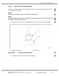
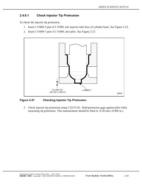
To check the injector tip protrusion:<br />
1. Insert J 33880-3 part of J 33880, into injector tube bore of cylinder head. See Figure 2-22.<br />
2. Insert J 33880-7 part of J 33880, into pilot. See Figure 2-27.<br />
Figure 2-27<br />
<strong>Check</strong>ing <strong>Injector</strong> <strong>Tip</strong> <strong>Protrusion</strong><br />
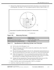
3. <strong>Check</strong> injector tip protrusion using J 22273-01. Hold protrusion gage against pilot while<br />
measuring tip protrusion. This measurement should be flush to -0.20 mm (-0.008 in.).<br />
All information subject to change without notice. (Rev. 01/04)<br />
6SE483 0303 Copyright © 2003 DETROIT DIESEL CORPORATION From Bulletin 16-60-03Rev. 2-45
2.4A N3 ELECTRONIC UNIT INJECTOR<br />
2.4A N3 ELECTRONIC UNIT INJECTOR<br />
Engine models built after December 1, 2003 will use the N3 Electronic Unit <strong>Injector</strong><br />
(EUI). See Figure 2-27a. The N3 injector is designed as an inline concept. The fuel metering<br />
unit or module is positioned under the plunger, so the overall envelope of the N3 is smaller than<br />
previous injectors. The N3 has an inwardly opening of solenoid valve which controls beginning<br />
of injection and end of injection. The solenoid valve closing point defines the beginning of<br />
injection (BOI) and the solenoid valve opening point defines the end of injection (EOI). Pressure<br />
is generated by the downward movement of the plunger in combination with the closed solenoid<br />
valve. Fuel quantity is metered by the length of time the solenoid valve remains closed. A<br />
magnetic core is incorporated into the module. The electrical leads from the core are brought to<br />
an external position on the injector through a modular two-pin connector socket.<br />
The advantages of the N3 injector are:<br />
Improved strength.<br />
Reduced external leakage potential.<br />
Compact design.<br />
Reduced weight.<br />
The amount of fuel injected and the beginning of injection timing is determined by the ECU.<br />
The ECU sends a command pulse which activites the injector solenoid. The N3 EUI performs<br />
four functions:<br />
Creates the high-fuel pressure required for efficient injection.<br />
Meters and injects the exact amount of fuel to handle the load.<br />
Atomizes the fuel for mixing with the air in the combustion chamber.<br />
Permits continous fuel flow for component cooling.<br />
Engine combustion is obtained by injecting, under pressure, a small quantity of accurately<br />
metered and finely atomized fuel oil into the cylinder. Metering and timing of the fuel is<br />
accomplished by the ECU which actuates the solenoid control valve to stop the free flow of fuel<br />
through the injector. When the solenoid control valve closes, fuel is trapped in the injector body<br />
and under the plunger. The continuous fuel flow through the injector prevents air pockets in the<br />
fuel system and cools those injector parts subjected to high combustion temperatures.<br />
(Rev. 01/04)<br />
All information subject to change without notice.<br />
2-46 From Bulletin 16-60-03Rev. 6SE483 0303 Copyright © 2003 DETROIT DIESEL CORPORATION
SERIES 60 SERVICE MANUAL<br />
1. <strong>Injector</strong> Follower 4. <strong>Injector</strong> Nut<br />
2. Plunger 5. <strong>Injector</strong> Spring Cage<br />
3. Module 6. Nozzle<br />
Figure 2-27a<br />
N3 Electronic Unit <strong>Injector</strong> Cross-Section<br />
All information subject to change without notice. (Rev. 01/04)<br />
6SE483 0303 Copyright © 2003 DETROIT DIESEL CORPORATION From Bulletin 16-60-03Rev. 2-46a
2.4A N3 ELECTRONIC UNIT INJECTOR<br />
Fuel enters the injector through the fuel inlet opening located around the injector<br />
body. See Figure 2-27b.<br />
Figure 2-27b<br />
Fuel <strong>Injector</strong> Body<br />
(Rev. 01/04)<br />
All information subject to change without notice.<br />
2-46b From Bulletin 16-60-03Rev. 6SE483 0303 Copyright © 2003 DETROIT DIESEL CORPORATION
SERIES 60 SERVICE MANUAL<br />
Outlet openings through which the excess fuel oil returns to the fuel return manifold and then<br />
back to the fuel tank, are located around the injector nut. See Figure 2-27c.<br />
Figure 2-27c<br />
N3 Electronic Unit <strong>Injector</strong><br />
All information subject to change without notice. (Rev. 01/04)<br />
6SE483 0303 Copyright © 2003 DETROIT DIESEL CORPORATION From Bulletin 16-60-03Rev. 2-46c
2.4A N3 ELECTRONIC UNIT INJECTOR<br />
After entering the nut cavity, the fuel passes through a drilled passage into the module and<br />
plunger area. See Figure 2-27a.<br />
The plunger operates up and down in the body bore of the injector. The motion of the injector<br />
rocker arm is transmitted to the plunger and follower that bears against the follower spring.<br />
As the piston moves approximately two-thirds of the way up in the cylinder on the compression<br />
stroke, the injector cam lobe begins to lift causing the injector rocker arm to push down on the<br />
follower and the plunger. Just before injection begins, the ECU sends an electronic pulse which<br />
turns on the injector solenoid. The energized solenoid creates a magnetic force which closes the<br />
control valve and traps fuel under the plunger and passages leading down to the needle valve. The<br />
fuel pressure increases as the plunger continues its downward stroke.<br />
This fuel pressure acts on the needle valve. When it creates a force high enough to overcome the<br />
valve spring force holding the needle on its seat, the needle valve moves up, allowing the high<br />
pressure fuel to spray into the combustion chamber. The high pressure of the fuel passing through<br />
the small holes in the nozzle creates a finely atomized spray for combustion within the cylinder.<br />
After the pulse width time has passed, the ECU turns off the current to the injector solenoid. The<br />
de-energized solenoid allows a spring to open the control valve, permitting the trapped fuel to<br />
spill down, dropping the pressure within the injector. When the pressure is low enough the<br />
needle valve closes and ends injection<br />
The beginning of injection and metering of the fuel in relation to the crankshaft position are<br />
controlled by the ECU. Injection begins soon after the control valve is closed. The valve closing<br />
point known as the injector response time is returned to the ECU. This information is used to<br />
monitor and adjust injection timing, thus removing injector-to-injector variation influences on<br />
timing. The amount of fuel injected depends on the pulse width stored in the calibration which<br />
determines how long the control valve remains closed; the larger the pulse width the longer the<br />
valve is closed and the more fuel is injected.<br />
When the injector rocker arm has completed its downward travel the injector follower spring<br />
returns it to the starting position. As the plunger moves up fuel enters the injector pumping cavity<br />
for another injection cycle. The constant circulation of fuel through the injector renews the fuel<br />
supply in the chamber and aids the cooling of the injector.<br />
(Rev. 01/04)<br />
All information subject to change without notice.<br />
2-46d From Bulletin 16-60-03Rev. 6SE483 0303 Copyright © 2003 DETROIT DIESEL CORPORATION
SERIES 60 SERVICE MANUAL<br />
2.4a.1<br />
Replacement of N3 Electronic Unit <strong>Injector</strong><br />
To determine if replacement is necessary perform the following procedure. See Figure 2-27d.<br />
NOTICE<br />
If the solenoid on N3 Electronic Unit <strong>Injector</strong> is faulty the injector<br />
must be replaced. The solenoid is not repairable.<br />
Figure 2-27d<br />
Flowchart for Replacement of N3 Electronic Unit <strong>Injector</strong><br />
2.4a.2<br />
Removal of N3 Elecronic Unit <strong>Injector</strong><br />
The following steps must be performed prior to removing an injector:<br />
1. Clean the valve rocker cover around its seat on the head, and in the attaching bolt recesses.<br />
[a] To remove the one-piece rocker cover, refer to section 1.6.2.<br />
All information subject to change without notice. (Rev. 01/04)<br />
6SE483 0303 Copyright © 2003 DETROIT DIESEL CORPORATION From Bulletin 16-60-03Rev. 2-46e
2.4A N3 ELECTRONIC UNIT INJECTOR<br />
[b] To remove the two-piecerocker cover, refer to section 1.6.3.<br />
[c] To remove the three-piece rocker cover, refer to section 1.6.5.<br />
To avoid injury from flying debris when using compressed<br />
air, wear adequate eye protection (face shield or safety<br />
goggles) and do not exceed 40 psi (276 kPa) air pressure.<br />
NOTICE:<br />
All the fuel must be removed from the cylinder head before<br />
removing an injector to prevent the fuel from entering the<br />
cylinder and causing hydrostatic lock or washdown. If the head<br />
is not thoroughly purged of fuel before an injector is removed,<br />
fuel remaining in the fuel manifold will drain into the cylinder<br />
filling the piston dome recess. It cannot drain from the dome<br />
and, if not removed, can cause hydrostatic lock and bend the<br />
connecting rod.<br />
NOTICE:<br />
Do not exceed 40 psi (276 kPa) when blowing compressed air<br />
into the cylinder head inlet fitting.<br />
2. Drain the cylinder head fuel gallery by removing the inlet and outlet lines from the fittings<br />
at the rear of the cylinder head. Blow low pressure compressed air into the inlet fitting for<br />
20 to 30 seconds or until all of the fuel is purged from the cylinder head. See Figure 2-27e.<br />
NOTE:<br />
Loosening the fuel line at the inlet fitting will allow fuel to flow faster. Carefully collect the<br />
drained fuel in an appropriate container.<br />
(Rev. 01/04)<br />
All information subject to change without notice.<br />
2-46f From Bulletin 16-60-03Rev. 6SE483 0303 Copyright © 2003 DETROIT DIESEL CORPORATION
SERIES 60 SERVICE MANUAL<br />
Figure 2-27e<br />
Cylinder Head Fuel Fitting Locations<br />
3. Remove the two rocker shaft through-bolts and one nut for each rocker shaft assembly,<br />
and lift the rocker shaft assembly off the engine. Refer to section 1.3.2.<br />
Remove the N3 injector as follows:<br />
NOTE:<br />
Do not pry on injector connector at anytime.<br />
1. Disengage the locking tang on the harness plug connector. Grasp the connector and gently<br />
pull it from the socket.<br />
2. Remove injector hold down bolt and washer.<br />
All information subject to change without notice. (Rev. 01/04)<br />
6SE483 0303 Copyright © 2003 DETROIT DIESEL CORPORATION From Bulletin 16-60-03Rev. 2-46g
2.4A N3 ELECTRONIC UNIT INJECTOR<br />
NOTICE:<br />
Extremecareshould be used when handling an N3 EUI to avoid<br />
costly damage by dropping or otherwise mishandling the N3 EUI.<br />
NOTICE<br />
TheN3EUImustberemovedfromthecylinderheadbyapplying<br />
forceonthebody surface as shown in Figure 2-27f. Removal<br />
force must not be applied to any other area on the N3 injector.<br />
Figure 2-27f<br />
N3 <strong>Injector</strong> Removal Surface<br />
(Rev. 01/04)<br />
All information subject to change without notice.<br />
2-46h From Bulletin 16-60-03Rev. 6SE483 0303 Copyright © 2003 DETROIT DIESEL CORPORATION
SERIES 60 SERVICE MANUAL<br />
3. Lift the injector from its seat in the cylinder head by inserting a pry bar under the hold<br />
down clamp and remove as a assembly both clamp and injector. See Figure 2-27g .<br />
Figure 2-27g<br />
Removal of the N3 <strong>Injector</strong><br />
NOTICE:<br />
Avoid wire brushing the spray holes to prevent damage.<br />
4. Cover the injector hole in the cylinder head to keep out foreign material. Remove carbon<br />
from the injector exterior in the area where the tip joins the nut, using wire buffing<br />
wheel, J 7944.<br />
2.4a.3<br />
Disassembly of N3 Electronic Unit <strong>Injector</strong><br />
On a Series 60 engine that uses the N3 EUI, only the injector seal rings and copper washer are<br />
servicable. The injector must not be disassembled.<br />
2.4a.4<br />
Installation of the N3 Electronic Unit <strong>Injector</strong><br />
Perform the following steps:<br />
1. If the fuel system is contaminated with coolant:<br />
[a] Drain the fuel tanks and refill with clean fuel. Refer to section 13.13.2.<br />
[b] Replace both filters with new, and clean the fuel/water separator, if<br />
equipped. Refer to section 2.8.2.<br />
[c] Inspect fuel injectors for damage and replace as required.<br />
All information subject to change without notice. (Rev. 01/04)<br />
6SE483 0303 Copyright © 2003 DETROIT DIESEL CORPORATION From Bulletin 16-60-03Rev. 2-46i
2.4A N3 ELECTRONIC UNIT INJECTOR<br />
2. If the coolant sysem is contaminated with fuel, flush and reverse flush the<br />
system. Refer to section 13.13.4.<br />
To avoid injury from flying debris when using compressed<br />
air, wear adequate eye protection (face shield or safety<br />
goggles) and do not exceed 40 psi (276 kPa) air pressure.<br />
NOTICE:<br />
Leftover fuel must be removed from the injector bore before<br />
injector installation. If fuel is trapped between the top of the<br />
injector hole tube and the lower injector O-ring seal, it may seep<br />
down to the injector hole tube seal ring, causing swelling and<br />
possable seal leakage.<br />
3. Using clean compressed air, blow out any fuel remaining in the injector bore.<br />
NOTICE:<br />
<strong>Injector</strong> O-ring seals and copper seals are considered one-use<br />
items and cannot be reused. Any time an injector is removed,<br />
all three injector O-ring seals and copper seal must be replaced<br />
with new parts. Failure to replace O-ring seals and copper seal<br />
can result in leakage.<br />
4. <strong>Check</strong> to make sure the injector bore is throughly clean.<br />
NOTE:<br />
The injector tube bore should be cleaned and inspected for damage before installation of<br />
the N3 Electronic Unit <strong>Injector</strong>. Refer to section 2.4b.1.1.<br />
5. Install new copper seal on injector, ensure contured side faces toward the injector.<br />
NOTE:<br />
All external O-rings must be lubricated prior to installation into the cylinder head.<br />
(Rev. 01/04)<br />
All information subject to change without notice.<br />
2-46j From Bulletin 16-60-03Rev. 6SE483 0303 Copyright © 2003 DETROIT DIESEL CORPORATION
SERIES 60 SERVICE MANUAL<br />
6. Apply a thin coat of clean fuel oil to the injector seal rings and install them in the injector<br />
nut ring grooves. Make sure the seals are properly seated see Figure 2-27h.<br />
Figure 2-27h<br />
N3 <strong>Injector</strong> Seal Rings<br />
All information subject to change without notice. (Rev. 01/04)<br />
6SE483 0303 Copyright © 2003 DETROIT DIESEL CORPORATION From Bulletin 16-60-03Rev. 2-46k
2.4A N3 ELECTRONIC UNIT INJECTOR<br />
7. Install the injector and hold down clamp as an assembly into its respective injector tube<br />
bore. Align the hold down clamp over the retaining stud, install the washer and bolt into<br />
injector clamp and torque to 55-65 N·m (40-48 lb·ft). See Figure 2-27i.<br />
1. <strong>Injector</strong> Clamp 4. N3 <strong>Injector</strong><br />
2. Bolt 5. N3 <strong>Injector</strong> Installed<br />
3. Washer<br />
Figure 2-27i<br />
N3 <strong>Injector</strong> and Related Parts<br />
(Rev. 01/04)<br />
All information subject to change without notice.<br />
2-46l From Bulletin 16-60-03Rev. 6SE483 0303 Copyright © 2003 DETROIT DIESEL CORPORATION
SERIES 60 SERVICE MANUAL<br />
8. Install the N3 EUI harness plug into the injector connector making sure the locking tang<br />
clicks into place. See Figure 2-27j.<br />
Figure 2-27j<br />
N3 <strong>Injector</strong> and Harness Connection<br />
9. Install the rocker arm shafts, with rocker arms in place. Refer to section 1.3.3.<br />
10. Adjust the intake and exhaust valve clearances and injector height. Refer to section 12.2.<br />
11. Install the inlet and outlet fuel lines to the fittings at the rear of the cylinder<br />
head. See Figure 2-6.<br />
12. On DDEC V engines, record the injector calibration code from the name plate with the<br />
proper cylinder location see Figure 2-27j.<br />
13. Install the valve rocker cover. Refer to section 1.6.7.<br />
14. For one-piece valve rocker cover, refer to section 1.6.8. For two-piece and three piece<br />
valve rocker cover, refer to section 1.6.9.<br />
15. Verify installation of N3 Electronic Unit <strong>Injector</strong>. Refer to section 11.8.<br />
All information subject to change without notice. (Rev. 01/04)<br />
6SE483 0303 Copyright © 2003 DETROIT DIESEL CORPORATION From Bulletin 16-60-03Rev. 2-46m
2.4B FUEL INJECTOR TUBE<br />
2.4B FUEL INJECTOR TUBE<br />
The bore in the cylinder head for the N3 EUI is directly through the cylinder head water jacket.<br />
To prevent coolant from contaminating the injector and still maintain maximum cooling of the<br />
injector, a stainless steel tube is screwed into the injector bore. The tube has a O-ring installed<br />
to create a water and gas-tight seal.<br />
NOTE:<br />
It is recommended that the injector tube be replaced with new a O-ring at the time of<br />
engine over haul. The injector tube is reusable.<br />
NOTE:<br />
Do not remove the injector tube for inspection unless a fault in the tube is suspected.<br />
2.4b.1<br />
Removal of the <strong>Injector</strong> Tube<br />
Perform the following steps to remove the injector tube:<br />
1. Remove Rocker Shaft assemblies. Refer to section 1.3.2.<br />
2. Remove N3 injector. Refer to section 2.4a.2.<br />
NOTICE:<br />
Engine coolant must be drained prior to injector tube removal.<br />
3. Dra in engine c oolant. Refer to section 13.13.4.<br />
NOTICE:<br />
Do not use excessive force on the injector tube during removal,<br />
cracking of the injector tube may occur requiring replacement.<br />
4. Install tool J 46904 into injector bore and align tool with slots in tube and turn counter<br />
clockwise to remove.<br />
2.4b.1.1<br />
Inspection of <strong>Injector</strong> Tube<br />
Inspect the injector tube as follows:<br />
1. Inspect injector tube for cracks or defects. If defective replace injector tube.<br />
2. Clean injector tube threads with a fine wire brush, being careful not to abrade the cylinder<br />
head to injector tube sealing surface.<br />
3. Clean the injector tube interior sealing surface, a chemical solvent maybe used for<br />
cleaning interior sealing surface.<br />
(Rev. 01/04)<br />
All information subject to change without notice.<br />
2-46n From Bulletin 16-60-03Rev. 6SE483 0303 Copyright © 2003 DETROIT DIESEL CORPORATION
SERIES 60 SERVICE MANUAL<br />
2.4b.2<br />
Installation of <strong>Injector</strong> Tube and Seal<br />
Perform the following steps for injector tube installation:<br />
1. Clean injector bore of debris.<br />
NOTE:<br />
Replace with new O-ring when injector tube is removed or replaced.<br />
2. Install O-ring in groove on injector tube, a small amount of silicone based O-ring<br />
lubrication will aid in the installation. See Figure 2-27k.<br />
Figure 2-27k<br />
<strong>Injector</strong> Tube and O-ring<br />
3. Coat the threads of injector tube with a high temperature nickel based antiseize lubricant.<br />
All information subject to change without notice. (Rev. 01/04)<br />
6SE483 0303 Copyright © 2003 DETROIT DIESEL CORPORATION From Bulletin 16-60-03Rev. 2-46o
2.4B FUEL INJECTOR TUBE<br />
4. Install the injector tube on tool J 46904. See Figure 2-27l.<br />
Figure 2-27l Installation of <strong>Injector</strong> Tube on Tool J 46904<br />
5. Using tool J 46904 install injector tube in injector bore. See Figure 2-27m.<br />
Figure 2-27m<br />
Installation of <strong>Injector</strong> Tube in Cylinder Head<br />
(Rev. 01/04)<br />
All information subject to change without notice.<br />
2-46p From Bulletin 16-60-03Rev. 6SE483 0303 Copyright © 2003 DETROIT DIESEL CORPORATION
SERIES 60 SERVICE MANUAL<br />
6. Torque injector tube to 35-45 N·m (26-33 lb·ft).<br />
7. Release torque approximately 180 degrees.<br />
8. Torque injector tube to 35-45 N·m (26-33 lb·ft) ensure the tip of the injector tube is flush<br />
or below the fire deck, the tube should not protrude.<br />
All information subject to change without notice. (Rev. 01/04)<br />
6SE483 0303 Copyright © 2003 DETROIT DIESEL CORPORATION From Bulletin 16-60-03Rev. 2-46q
2.5 FUEL PUMP WITH SEPARATE DRIVE SHAFT AND HUB<br />
2.5 FUEL PUMP WITH SEPARATE DRIVE SHAFT AND HUB<br />
The former fuel pump system consists of the following components:<br />
Barnes positive displacement type fuel pump; separate drive shaft<br />
Air compressor drive hub<br />
Gear train mounting adaptorThis pump has been replaced, effective July 1995, with an<br />
improved fuel pump. The pumps are similar, except the improved pump has a one-piece<br />
drive. These pump assemblies are completely interchangeable. Components are not<br />
interchangeable.<br />
(Rev. 01/04)<br />
All information subject to change without notice.<br />
2-46r From Bulletin 16-60-03Rev. 6SE483 0303 Copyright © 2003 DETROIT DIESEL CORPORATION