Common Rail Tester - diagtools ltd
Common Rail Tester - diagtools ltd
Common Rail Tester - diagtools ltd

You also want an ePaper? Increase the reach of your titles
YUMPU automatically turns print PDFs into web optimized ePapers that Google loves.
<strong>Common</strong> <strong>Rail</strong> <strong>Tester</strong><br />
FOREWARD<br />
This manual is intended for use by service technicians to help provide efficient and correct service on CRDi<br />
vehicles using <strong>Common</strong> <strong>Rail</strong> <strong>Tester</strong>.<br />
To ensure customer satisfaction with Nextech product, it is essential quick and accurate service operation<br />
as well as reasonable price.<br />
Consequently, it is important that the service personnel fully understand the contents of this manual, which<br />
should be kept within reach for future reference.<br />
All information in this manual including photographs, drawings, and specifications is current<br />
at the time of publication.<br />
Nextech reserves the right to make any changes to the design or to make additional improvements in this<br />
manual.<br />
No part of this manual hereon may be reproduced or used in any form of by any means – graphic,<br />
electronic, or mechanical, including photocopying, recording, taping, or information storage and retrieval<br />
systems – without written permission of the publisher.<br />
DEC ,2005, Printed in Korea<br />
1<br />
CONTENTS<br />
1. GENERAL<br />
2. COMPONENTS<br />
3. PARTS INDEX<br />
4. DIGNOSIS<br />
4-1. DIAGNOSIS PROCEDURE ACCORDING TO SYMPTOM<br />
4-2. LOW PRESSURE FUEL LINE TEST<br />
4-3. INJECTOR BACK LEAK TEST (STATIC)<br />
4-4. INJECTOR BACK LEAK TEST (DYNAMIC)<br />
4-5. HIGH PRESSURE PUMP TEST<br />
4-6. PRESSURE CONTROL VALVE TEST<br />
5. FUEL LINE FLUSHING<br />
6. DIAGNOSIS CHECK SHEET<br />
2
1. GENERAL<br />
This <strong>Tester</strong> has been developed to diagnose efficiently and accurately for diesel vehicles with<br />
common rail system.<br />
1-1. Criteria of diagnosis using Commom <strong>Rail</strong> <strong>Tester</strong><br />
Impossible to start engine or engine stall while driving<br />
※ It would be recommended performing Power Balance Test by Hi-Scan (for Bosch system) or<br />
by disconnecting injector's connecter one by one (for Delphi system),<br />
if vehicle has problem beside the above symptoms such as engine vibration or<br />
emission of black/white smoke while engine idle.<br />
The problem may be due to differences of the injected amount in each injector.<br />
1-2. Notice<br />
A CRDi system has been constructed using precision-made components.<br />
If an extremely small foreign particle enters the system during service, it may cause sticking or<br />
clogging of injectors.<br />
Therefore, be sure to eliminate any dust or contaminated deposits on or around the engine and<br />
fuel lines during service. 3<br />
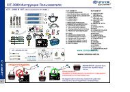
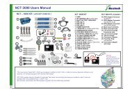
2. COMPONNENTS<br />
1<br />
2 3<br />
4 5<br />
M12mm<br />
8<br />
7<br />
9<br />
17<br />
11<br />
19<br />
18<br />
20<br />
21<br />
22 23<br />
1. Tool Case<br />
2. Regulator Valve<br />
3. Plug(for Delphi)<br />
4. Plug(for Bosch)<br />
5. Regulator Valve Adapter(for SM model)<br />
6. Flask & Holder<br />
7. Visible Tube<br />
8. Injector return hose adapter<br />
9. Injector return hose plug<br />
10. Clean Case<br />
11. Dust Cap<br />
12. High pressure gauge<br />
13. Adapter connector (for Delphi old)<br />
14. Adapter connector(for Delphi new)<br />
15. Adapter connector(for Bosch)<br />
16. Pressure Control Valve cable<br />
17. Vacuum Gauge<br />
18. Low pressure gauge<br />
19. Gauge connection tube<br />
20. Connection Adapter<br />
21. Connection adapter with hose<br />
22. Fuel Filter Plug<br />
23. User's Manual<br />
6<br />
12 13 14 15<br />
10<br />
16<br />
4
3. PARTS INDEX<br />
NO Part Name Part no. Quantity Figure<br />
<strong>Common</strong> <strong>Rail</strong> <strong>Tester</strong> CRT-1000 1SET<br />
1 Tool Case CRT-1010 1EA<br />
2 Regulator Valve CRT-1020 1SET<br />
3 Plug(for Delphi) M14mm CRT-1021 3EA<br />
4 Plug(for Bosch) M12mm CRT-1022 3EA<br />
5<br />
Regulator Valve Adapter<br />
(for SM Model))<br />
CRT-1023<br />
1EA<br />
6 Flask & Holder CRT-1030 1SET<br />
5<br />
3. PARTS INDEX<br />
NO Part Name Part no. Quantity Figure<br />
7 Visible Tube CRT-1031 4EA<br />
8<br />
Injector Return Hose<br />
Adapter<br />
CRT-1032<br />
4EA<br />
9 Injector Return Hose Plug CRT-1033 1EA<br />
10 Clean Case CRT-1034 1EA<br />
11 Dust Cap CRT-1035 8EA<br />
6
3. PARTS INDEX<br />
NO Part Name Part no. Quantity Figure<br />
12 High Pressure Gauge CRT-1040 1SET<br />
13<br />
Adapter Connector<br />
(for Delphi Old)<br />
CRT-1041<br />
1EA<br />
14<br />
Adapter Connector<br />
(for Delphi New)<br />
CRT-1042<br />
1EA<br />
15<br />
Adapter Connector<br />
(for Bosch)<br />
CRT-1043<br />
1EA<br />
16 Pressure Control Valve Cable CRT-1044 1SET<br />
7<br />
3. PARTS INDEX<br />
NO Part Name Part no. Quantity Figure<br />
17 Vacuum Gauge CRT-1050 1EA<br />
18 Pressure Gauge CRT-1051 1EA<br />
19 Gauge Connection Tube CRT-1052 1EA<br />
20 Connection Adapter CRT-1053 1EA<br />
21<br />
Connection Adapter With<br />
Hose<br />
CRT-1054<br />
1EA<br />
22 Fuel Filter Plug CRT-1055 1EA<br />
23 User's Manual CRT-1055 1EA<br />
8
4. DIAGNOSIS<br />
4-1. DIAGNOSIS PROCEDURE ACCORDING TO SYMPTOM<br />
1) When the engine is not able to start<br />
1 Low Pressure Line Test → 2 Injector Back Leak Test (Static Test) →<br />
3 High Pressure Line Test<br />
2) When the engine is able to start<br />
1 Low Pressure Line Test → 2 Injector Back Leak Test (Dynamic Test) →<br />
3 High Pressure Line Test<br />
4-2. LOW PRESSURE FUEL LINE TEST<br />
1) Remove fuel hose from fuel filter and connect low pressure gauge (CRT-1051) or<br />
vacumn gauge (CRT-1050) according to engine system as shown.<br />
* Additional parts needed: tube for gauge connection (CRT-1052),<br />
Connection adapter with hose (CRT-1054), connection adapter (CRT-1053)<br />
Fuel Filter Plug (CRT-1055)<br />
2) Start the engine and keep idle approxmately 5seconds, then turn of the engine.<br />
9<br />
4. DIAGNOSIS<br />
Internal suction pump type (Bosch Type Ⅰ)<br />
b<br />
b Vacuum Gauge<br />
c Test Tube Assay<br />
d Connection Adapter<br />
b<br />
Vacuum Gauge<br />
d<br />
c<br />
d<br />
c<br />
10
4. DIAGNOSIS<br />
a<br />
Electric pump type (Bosch Type Ⅱ)<br />
c<br />
a Low Pressure Gauge<br />
c Test Tube Assay<br />
d Connection Adapter<br />
e Connection Adapter with<br />
Hose<br />
e<br />
f Hose Clamp<br />
Pressure Gauge<br />
Pressure Gauge<br />
d<br />
f<br />
Fuel pump<br />
(Electric)<br />
11<br />
4. DIAGNOSIS<br />
Internal suction pump type (Delphi)<br />
b<br />
b<br />
b Vacuum Gauge<br />
c Test Tube Assay<br />
d Connection Adapter<br />
g Fuel Filter Plug<br />
d<br />
c<br />
g<br />
g<br />
12
4. DIAGNOSIS<br />
3) Read the fuel pressure or suction pressure indicated.<br />
4) Judgement<br />
Electric pump type (Bosch Type Ⅱ)<br />
CASE PRESSURE (bar) JUDGEMENT<br />
1 1.5~3 kg/cm2 System normal<br />
2 4~6 kg/cm2 Filter or fuel line clogging<br />
3 0~1.5 kg/cm2 Pump or fuel line leak<br />
Internal suction pump type (Bosch Type Ⅰ and Delphi)<br />
CASE VACUUM JUDGEMENT<br />
1 8~19 cmHg System normal (good condition)<br />
2 20~60 cmHg Filter or fuel line clogging (pump in good condition)<br />
3 0~7 cmHg Air leak in to the system or Suction pump damage<br />
13<br />
4. DIAGNOSIS<br />
4-3. INJECTOR BACK LEAK TEST (STATIC)<br />
1) Remove the return hose from each injector and Install injector return hose adapter (CRT-1032),<br />
visible tubes (CRT-1031) and connect the visible tube's end to the flasks (CRT-1030).<br />
2) Disconnect "A" point on the fuel return hose in below photograph and block the fuel return hose<br />
in the direction of the high pressure pump with injector return hose plug (CRT-1033).<br />
3) Connect the adapter connector (CRT-1041,CRT-1042,CRT-1043) to rail pressure sensor and<br />
connect high pressure gauge (CRT-1040) as shown.<br />
4) Disconnect the injector connectors to prevent its operating.<br />
"A"<br />
High-pressure Gauge<br />
Injector return<br />
hose plug<br />
Adapters for<br />
rail pressure<br />
sensor<br />
Injector return<br />
hose adapter<br />
14
4. DIAGNOSIS<br />
Delphi, Bosch TypeⅠ<br />
5) Remove the Inlet Metering Valve connector to allow fuel feeding to high pressure line.<br />
Bosch Type Ⅱ<br />
5) Disconnect the Pressure Control Valve connector and connect the pressure control valve cable<br />
(CRT-1044) to the Pressure Regulator Valve, and then connect pressure control valve cable<br />
(CRT-1044)'s lead to battery so that pressure control valve will block fuel return from rail.<br />
Bosch Type Ⅲ<br />
5) Perform No. 5) procedure both Bosch TypeⅠand Bosch Type Ⅱ so that fuel will be supplied to the high<br />
pressure line and pressure control valve will block fuel return from the rail.<br />
PCV<br />
IMV connector<br />
● Delphi, Bosch TypeⅠ,Bosch Type Ⅲ<br />
Pressure control<br />
valve cable<br />
● Bosch Type Ⅱ, Bosch Type Ⅲ<br />
※ Notice : Do not supply the battery power over<br />
5 minutes. It may cause to damage PCV.<br />
15<br />
4. DIAGNOSIS<br />
* Engine Type<br />
Delphi : J3(2.9L)<br />
Bosch TypeⅠ : D4CB(2.5A-ENG)<br />
Bosch Type Ⅱ : D3EA(1.5D-ENG), D4EA(2.0D-ENG),<br />
Bosch Type Ⅲ : D4FA(1.5U-ENG)<br />
6) Crank the engine once for 5 seconds.<br />
※ Do not exceed the 5seconds in any case.<br />
※ Cranking RPM must exceed 200 RPM.<br />
Sensor abnormalLow pressure Normal<br />
※ Perform the test under 30℃ with coolant temperature (If the fuel pressure test performed over<br />
30℃, the fuel pressure indicated may be diffrent accoding to fuel viscosity change.).<br />
7) Read the pressure from high pressure gauge (CRT-1040) and measure the amount of fuel contained<br />
at each visible tube (CRT-1031).<br />
8) Judgement<br />
CASE PRESSRUE(bar) INJECTOR BACK LEAK JUDGEMENT FACTOR TO BE CHECKED<br />
1<br />
1000~1800<br />
(above 1000)<br />
0~200mm<br />
(below 200)<br />
Normal<br />
2<br />
0~1000<br />
(below 1000)<br />
200~400<br />
(above 200)<br />
Faulty injector<br />
(excessive back leak)<br />
Replace injector if there is only<br />
excessive back leak (over 200mm).<br />
3<br />
0~1000<br />
(below 1000)<br />
0~200<br />
(below 200)<br />
HP Pump<br />
(Insufficient pressure)<br />
Conduct the high pressure pump<br />
test<br />
16
4. DIAGNOSIS<br />
Limit: 200mm<br />
Sensor abnormal Low pressure Normal<br />
4- 4. INJECTOR BACK LEAK TEST (DYNAMIC)<br />
1) Remove the return hose from each injector and Install injector return hose adapter (CRT-1032),<br />
visible tubes (CRT-1031), flasks (CRT-1030) and injector return hose plug (CRT-1033) referring to<br />
Injetor back leak test (STATIC) in previous page.<br />
2) Conduct the high pressure leak test refering to following explanation.<br />
BOSCH Type Ⅰ,Ⅱ,Ⅲ : D3EA(1.5D-ENG), D4EA(2.0D-ENG), D4FA(U-ENG), D4CB(2.5A-ENG)<br />
3) Start engine → 1minute at idle → accelerate engine up to 3000 rpm and keep the 3000rpm for<br />
30seconds →Stop Engine<br />
4) When the test is completed, measure the amount of fuel in each flask (CRT-1030).<br />
30sec / 3000rpm<br />
Start 1min<br />
sto<br />
17<br />
4. DIAGNOSIS<br />
DELPHI : J3 (2.9L)<br />
3) Connect the Hi-Scan and select the 'High Pressure Leak Test' mode.<br />
4) Conduct the 'High Pressure Leak Test' untill the Hi-Scan finish the test automatically.<br />
or manualy : Start engine → 2minutes at idle → 3 times acceleration →Stop Engine<br />
※One acceleration: Accelerate up to 3800rpm for 2 seconds and keep idle for 2 seconds.<br />
Start<br />
2min<br />
Idle<br />
acceleratio<br />
Stop<br />
18
4. DIAGNOSIS<br />
5) For the accuracy of the test, perform the test more than twice and select<br />
the largest amount as a measured value.<br />
※ The flasks (CRT-1030) should be empty before the 2nd test started.<br />
6) Judgement<br />
BOSCH Type Ⅰ,Ⅱ,Ⅲ<br />
Replace the injector which is shown more 3 times than the minimum value.<br />
● Example<br />
Injectors Quantity back leaked Results<br />
Normal condition<br />
#2 Injector abnormal<br />
Cylinder 1 30<br />
Cylinder 2 61 Faulty injector<br />
Cylinder 3 20 Minimum value<br />
Cylinder 4 30<br />
1 2 3 44<br />
1 2 3 4<br />
DELPHI<br />
Replace the injector which indicates exceeds 25cc.<br />
Service Limit 25cc<br />
1 2 3 4<br />
Abnormal<br />
injector<br />
19<br />
4. DIAGNOSIS<br />
4-5. HIGH PRESSURE PUMP TEST<br />
1) Clean the regulator valve (CRT-1020), regulator valve adaptor (CRT-1023) and plugs (CRT-1021<br />
or CRT-1022) with diesel fuel.<br />
2) Remove all 4 fuel injector pipes from the common rail and disconnect the rail pressure<br />
sensor's connector.<br />
3) Install the regulator valve (CRT-1020), plugs (CRT-1021 or CRT-1022), dust caps (CRT-1035),<br />
adapter connector (CRT-1041, CRT-1042,CRT-1043) and High pressure gauge (CRT-1040)<br />
to the common rail securely as shown.<br />
※ Use regulator valve adaptor (CRT-1023) for Santafe(SM) model.<br />
※ Be sure that the regulator valve (CRT-1020) and the plugs (CRT-1021 or CRT-1022) have<br />
installed securely so that there will not be any fuel leakage.<br />
Delphi, Bosch TypeⅠ<br />
4) Disconnect the IMV connector from the high pressure pump.<br />
Bosch Type Ⅱ<br />
4) Disconnect Pressure Control Valve connector and connect the pressure control valve cable<br />
(CRT-1044) to the Pressure Regulator Valve, and then connect pressure control valve cable<br />
(CRT-1044)'s lead to battery so that pressure control valve will block fuel return from rail.<br />
Bosch Type Ⅲ<br />
4) Perform No. 4) procedure both Bosch TypeⅠand Bosch Type Ⅱ so that fuel will be supplied to<br />
the high pressure line and pressure control valve will block fuel return from the rail.<br />
20
4. DIAGNOSIS<br />
Purpose of the test : Inspection for mechanical capability of the High<br />
pressure pump (Maximum pressure check)<br />
Method : Check the pumping capability of the high pressure pump by<br />
actuating pump after blocking rail's outlets using the plug and<br />
regulator.<br />
Plug : Blocking the rail circuit<br />
Regulator Valve : Preventing over pressure of high pressure line<br />
Regulator<br />
valve<br />
Regulator valve<br />
adapter for<br />
Santafe<br />
Adapters for<br />
rail pressure sensor<br />
21<br />
4. DIAGNOSIS<br />
5) Crank the engine for 5-6 seconds.<br />
For the accuracy of the test, perform the test twice and select the higher pressure one<br />
as a measured value.<br />
6) Judgement<br />
If the fuel pressure indicated on the gauge is within the range of specification,<br />
the high pressure pump is normal.<br />
But if not, check the below items before the High pressure pump replaced.<br />
a. Check the plug or regulator valve if it leaks.<br />
b. If fuel pressure is lower than specification, test it again when coolant temperature is<br />
below 30℃.<br />
The pump is in normal condition if the pressure restores to normal range.<br />
c. In case of the system in which pressure control valve implemented,<br />
check the valve condition & internal leak and replace them if necessary.<br />
* Refer to '4-6 pressure control valve test' procedure<br />
Specification of high pressure of common rail :<br />
BOSCH System : 1000~1500 bars<br />
DELPHI System : 1050~1600 bars<br />
If fuel pressure indicated on the gauge is lower than specification there may be a problem in<br />
the rail pressure sensor or its circuit even fuel flows out from the regulator valve (CRT-1020). 22
4. DIAGNOSIS<br />
4-6. PRESSURE CONTROL VALVE TEST<br />
1) Remove fuel return connector from PCV upper.<br />
2) Remove fuel return hose from PCV lower.<br />
3) Disconnect Pressure Control Valve connector and connect<br />
the pressure control valve cable (CRT-1044) to the<br />
Pressure Control Valve, and then connect the pressure<br />
control valve cable (CRT-1044)'s lead to battery so that<br />
pressure control valve will block fuel return from rail.<br />
4) Put fuel return pipes to flasks(CRT-1030).<br />
5) Crank the engine for 5 seconds.<br />
6) Check fuel return amount.<br />
※ Service Limit : Less than 10cc (Fuel pressure must over 1000 bars)<br />
Fuel return connector<br />
Fuel return<br />
PCV<br />
Return Hose<br />
Pressure control<br />
valve cable<br />
Leaked fuel<br />
Limit ( 10cc/5sec)<br />
23<br />
5. FUEL LINE FLUSHING<br />
1) Before connecting the fuel pipes to the engine, be sure<br />
Fuel pipe<br />
Air gun nozzle<br />
that all the pipe outlet surfaces, inner passages, and especially fuel pipe<br />
fitting nuts are clean.<br />
Clean using air gun if necessary.<br />
2) Assemble all fuel pipes except the fuel pipe fitting nuts of injector side.<br />
3) Temporarily tighten the fuel pipe fitting nuts to injectors by hand after<br />
aligning the nuts to the injectors.<br />
4) To prevent contamination on engine room, wrap up around the injector pipe<br />
using paper towel or shop rag as shown.<br />
Cleaning by air gun<br />
5) Crank the engine 2 to 3 times for 5 to 6 seconds to flow out the fuel contamination<br />
from injector connection area.<br />
6) Tighten the nuts with specified torque using special tool.<br />
7) Erase the DTC code by Hi-Scan.<br />
Special tool<br />
Loosen the nuts<br />
Tighten the nuts<br />
Paper towel<br />
Fuel with contaminations<br />
Injecto<br />
24
6. DIAGNOSIS CHECK SHEET<br />
Model : VIN : Milage :<br />
NO Test items<br />
Value measured Result<br />
1<br />
Low Pressure Fuel Line Test<br />
( ) Kg/cm2<br />
( ) CmHg<br />
(Good, Failure)<br />
<strong>Rail</strong> pressure ( ) bars (Good, Failure)<br />
# 1 Cylinder ( ) Cm (Good, Failure)<br />
Static<br />
Amount of<br />
fuel<br />
in visible tube<br />
# 2 Cylinder ( ) Cm (Good, Failure)<br />
# 3 Cylinder ( ) Cm (Good, Failure)<br />
2<br />
Injector Back<br />
Leak Test<br />
# 4 Cylinder ( ) Cm (Good, Failure)<br />
# 1 Cylinder ( ) Cm (Good, Failure)<br />
Dynamic<br />
Amount of<br />
fuel<br />
in visible tube<br />
# 2 Cylinder ( ) Cm (Good, Failure)<br />
# 3 Cylinder ( ) Cm (Good, Failure)<br />
# 4 Cylinder ( ) Cm (Good, Failure)<br />
3 Fuel Pressure Test<br />
( ) bars (Good, Failure)<br />
25<br />
Tool supplier : Nextech Co., Ltd.<br />
Contact Point : Mr. Alex Lim<br />
Tel : +82-2-3140-1489 or 1443<br />
Fax : +82-2-3140-1449<br />
E-mail : sales@nex-tek.com<br />
26
QUALITY ASSURANCE<br />
Name of products: Commom <strong>Rail</strong> <strong>Tester</strong><br />
We hereby certify that the above product is guaranteed by our quality assurance policy and<br />
procedures listed below.<br />
Subject of assurance: All components contained in the <strong>Common</strong> <strong>Rail</strong> <strong>Tester</strong> as supplied to all Nextech<br />
distributors and dealers by Nextech Co., Ltd.<br />
Parts Guarantee<br />
Guarantee Period<br />
: Quality and Durability of each component.<br />
:1 Years from the date of purchase.<br />
Nextech Co., Ltd.<br />
President:<br />
27<br />
Seoul Korea<br />
Printing: SEP. 2005<br />
Publication No.: OSTS-20050901-E<br />
Printed in Korea