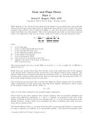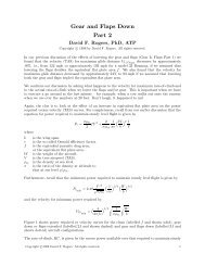
Flight Determination of Partial Span Flap Parasite ... - NAR Associates
Flight Determination of Partial Span Flap Parasite ... - NAR Associates
Flight Determination of Partial Span Flap Parasite ... - NAR Associates

Create successful ePaper yourself
Turn your PDF publications into a flip-book with our unique Google optimized e-Paper software.
<strong>Flight</strong> <strong>Determination</strong> <strong>of</strong> <strong>Partial</strong> <strong>Span</strong> <strong>Flap</strong><br />
<strong>Parasite</strong> Drag With <strong>Flap</strong> Deflection<br />
David F. Rogers ∗<br />
United States Naval Academy, Annapolis, Maryland 21402<br />
Nomenclature<br />
b = wing span.<br />
c = airfoil or wing chord.<br />
C l = Two dimensional section lift coefficient<br />
C Do =Dragcoefficient<br />
e = Oswald efficiency factor.<br />
f = aircraft equivalent parasite drag area.<br />
S = wing reference area.<br />
THP req = thrust horsepower required.<br />
THP req std<br />
= thrust horsepower required at standard weight and altitude.<br />
V = true airspeed.<br />
V std = standard airspeed.<br />
W = weight <strong>of</strong> the aircraft.<br />
W std = aircraft standard weight.<br />
δ f = flap deflection angle.<br />
ρ SL = density at sea level.<br />
σ = ratio <strong>of</strong> the density at altitude to that at sea level, ρ/ρ SL .<br />
Introduction<br />
Various lift enhancing devices are used to increase the operational speed range <strong>of</strong> aircraft,<br />
particularly at the low end near stall. Lower stall speeds decrease the landing distance.<br />
Fundamentally, there are only three techniques available for increasing the lift on an airfoil<br />
– camberline change, boundary layer control and area increase. Deflecting a trailing edge<br />
flap, drooping the leading edge <strong>of</strong> an airfoil or adding an external downward deflected<br />
leading edge slat are examples <strong>of</strong> devices that change the camber <strong>of</strong> the airfoil. Fixed<br />
leading edge slots, extensible leading edge slats and single or multiply slotted trailing edge<br />
flaps, as well as direct boundary layer blowing or suction, are examples <strong>of</strong> lift-enhancing<br />
devices that utilize boundary layer control. Fowler and multiple slotted trailing edge flaps<br />
and extensible leading edge slats are devices that depend on increasing area to enhance lift.<br />
Obviously, individual devices may use multiple methods for lift enhancement. Modern wing<br />
design typically incorporates both leading edge and trailing edge devices at the expense <strong>of</strong><br />
additional mechanical complexity.<br />
Typically, light general aviation aircraft <strong>of</strong> less than 6000 lbs depend on trailing edge<br />
flaps for lift enhancement. Full deflection <strong>of</strong> trailing edge flaps is used to increase the<br />
∗ Pr<strong>of</strong>essor Emeritus, Aerospace Engineering Department, 590 Holloway Road, Annapolis, Maryland 21402;<br />
dfr@nar-associates.com. Associate Fellow AIAA.<br />
Copyright c○2007-2009 David F. Rogers. All rights reserved. 1
approach and landing descent angles. Fully or partially deflected flaps may be used as<br />
speed brakes. Because small flap deflections result in proportionally greater increases in lift<br />
than in drag, partial flap extension may be used to decrease the take<strong>of</strong>f distance. <strong>Partial</strong><br />
flap extension may also be used to decrease the maneuvering turn radius. For multiengine<br />
aircraft, partial flap extension lift and drag characteristics are important for single engine<br />
climb performance. Typically, only partial span flaps are used because the trailing edge is<br />
also used for lateral control devices.<br />
A literature review revealed several early NACA technical reports, wartime reports<br />
and technical notes reporting wind tunnel experiments on NACA 230 mean line airfoils<br />
with slotted flaps, as well as a number <strong>of</strong> experiments on finite wings with full or partial<br />
span slotted flaps. The works <strong>of</strong> Wenzinger and Harris (Ref. 1) and House (Ref. 2) are<br />
representative <strong>of</strong> these efforts and particularly germaine to the present study.<br />
The experiments by Wenzinger and Harris compare and evaluate the characteristics <strong>of</strong><br />
an NACA 23012 airfoil with 0.2c split and plain flaps, along with 0.2667c external airfoil,<br />
Fowler and various single slotted flaps. They found that an optimum single slotted flap<br />
provided a superior maximum lift coefficient compared to split, plain and external airfoil<br />
flaps. However, the slot had to be carefully shaped and positioned to achieve optimal results.<br />
A Fowler flap provided a slightly higher maximum lift coefficient than the optimal single<br />
slotted flap but at the expense <strong>of</strong> additional complexity.<br />
House investigated the effects <strong>of</strong> center and tip located partial span flaps on finite wings<br />
<strong>of</strong> aspect ratio six. He concluded that center span flaps had higher values <strong>of</strong> maximum lift<br />
coefficient and that the values <strong>of</strong> C Lmax did not significantly change with an increase in flap<br />
span beyond 0.40b.<br />
The Aircraft<br />
The flight tests were conducted in an E33A Beech Bonanza. The aircraft had approximately<br />
600 hours on a recently installed Teledyne Continental Motors IO-520BB 285 BHP<br />
factory remanufactured six cylinder fuel injected engine. The aircraft has a fuel computer<br />
capable <strong>of</strong> measuring and displaying fuel flow and fuel remaining. The aircraft empty weight<br />
is 2142 lbs , including the weight <strong>of</strong> six gallons <strong>of</strong> unusable fuel and ten quarts <strong>of</strong> oil. The<br />
aircraft is equipped with a recently overhauled McCauley 3-blade propeller (3A32C76 hub<br />
with 82NB-2 blades) with a nominal diameter <strong>of</strong> 80 . The aircraft is fitted with a Century<br />
II autopilot and panel mounted IFR (Instrument <strong>Flight</strong> Rules) certified GPS avionics<br />
along with an S-TEC PSS60 altitude hold. This particular aircraft has the speed sweep<br />
windshield to reduce drag. Improved engine baffling for better engine cooling and reduced<br />
cooling drag has also been fitted. In addition, the Beechcraft “birdwing” antenna as well as<br />
the 10 ft belly ADF sense antenna have been removed to further reduce drag. The aircraft<br />
isshowninRogers(Ref.3).<br />
The Wing<br />
The aircraft wing span is 33.6 ft including wing tips (see Figure 1). The straight tapered<br />
wing has a taper ratio <strong>of</strong> 0.5. The quarter chord <strong>of</strong> the wing is unswept. The theoretical<br />
airfoil at the centerline <strong>of</strong> the aircraft is an NACA 23016.5 with a chord <strong>of</strong> 84 . The airfoil at<br />
the wing tip is an NACA 23012. The modified leading edge extension (LEX) at the aircraft<br />
centerline extends forward <strong>of</strong> the quarter chord by 37.6 , to yield a theoretical centerline<br />
Copyright c○2007-2009 David F. Rogers. All rights reserved. 2
chord <strong>of</strong> 100.6 . The leading edge <strong>of</strong> the LEX extends in a straight line from the leading<br />
edge <strong>of</strong> the theoretical centerline airfoil to intersect the leading edge <strong>of</strong> the straight tapered<br />
wing at station 47 to form a crank in the wing. There is a triangular spin strip at the crank<br />
<strong>of</strong> the wing. There is also a small 7.875 long triangular spin strip on the wing centered<br />
at wing station 70.4375. The wing has 3 ◦ <strong>of</strong> washout, varying linearly from the theoretical<br />
root section to the tip. The wing dihedral is 6 ◦ . The reference wing area is 181 ft 2 ,which<br />
yields a reference aspect ratio <strong>of</strong> 6.2.<br />
201.6<br />
47.0<br />
NACA 23012<br />
3.47<br />
42.0<br />
80.32<br />
Aileron hinge line<br />
Leading edge<br />
1/4 chord line<br />
Crank<br />
Fuselage side<br />
NACA 23016.5<br />
A/C centerline<br />
21.0<br />
84.0<br />
100.3<br />
4.77<br />
12.63 16.71<br />
15.1<br />
3.3<br />
<strong>Flap</strong> hinge line<br />
89.5<br />
20.0<br />
Figure 1. Wing schematic.<br />
The <strong>Flap</strong><br />
The single slotted flap extends from the fuselage sidewall outboard along the wing to<br />
station 109.3 (inches from the aircraft centerline), as shown in Figure 1. The flap chord at<br />
the inboard end is 20.0 and at the outboard end 15.1 . The individual flap span measured<br />
at the flap quarter chord is 87.2 . The planform area <strong>of</strong> an individual flap is 10.6ft 2 .<br />
The slot is well formed. At full flap deflection the trailing edge moves aft 2 from the<br />
stowed position. <strong>Flap</strong> deflection was measured at station 29 approximately 5 outboard <strong>of</strong><br />
the fuselage at the undeflected flap trailing edge. Both a manual jig and protractor and a<br />
digital inclinometer were used to measure the deflection. Maximum deflection was measured<br />
as 32 ◦ at this location.<br />
The <strong>Flight</strong> Tests<br />
The flight tests were conducted at a pressure altitude <strong>of</strong> 6000 ft . A box pattern was<br />
flown in order to acquire data for the horseshoe heading technique used to determine the<br />
true airspeed from the GPS ground speed (Ref. 4). Constant brake horsepower settings<br />
from 38% to 75% were used to set the airspeed for each data run and to remain below the<br />
Copyright c○2007-2009 David F. Rogers. All rights reserved. 3
maximum flap extension speed. The aircraft tachometer was calibrated against a stroboscopic<br />
tachometer and thereafter used to measure propeller RPM. The aircraft instrument<br />
was used to measure engine manifold pressure in order to determine power available. Mixture<br />
was set to correspond to best power (Ref. 5), i.e., approximately 100 ◦ rich <strong>of</strong> peak<br />
exhaust gas temperature. During the flight tests, aircraft weight varied from 3179 lbs to<br />
2669 lbs for the various flights. Outside air temperature (OAT) varied from 32 to 52 ◦ Ffor<br />
the various data runs. Typically the OAT remained nearly constant for each data run. Manifold<br />
pressure varied from approximately 18.2 Hg to 23.2 Hgin0.5to1 Hg increments,<br />
while propeller speed varied from approximately 1850 to 2500 RPM in approximately 100<br />
RPM increments. The clean configuration tests, i.e., gear and flaps retracted, were conducted<br />
with cowl flaps and all cabin vents closed. The gear down tests were conducted with<br />
cowl flaps open. Typically five or six data points were obtained for each flap setting during<br />
a single flight.<br />
Data Acquisition and Reduction<br />
The true airspeed was determined using the horseshoe heading technique as detailed by<br />
Rogers (Ref. 4) and the references therein. This technique has been shown to be as accurate,<br />
within less than ±1 kt, as a traditional trailing cone or Kiel tube (Ref. 6). Basically the<br />
flight test consists <strong>of</strong> flying three legs with headings ninety degrees apart while recording<br />
the GPS ground speed. Using these GPS ground speeds and headings and solving three<br />
algebraic equations in three unknowns yields the true airspeed, wind direction and wind<br />
speed.<br />
Aircraft weight was determined by subtracting the fuel used from the aircraft gross<br />
weight before engine start. Atmospheric density was determined from measured outside<br />
air temperature and the pressure altitude. Engine brake horsepower was determined from<br />
the manufacture’s engine charts (Ref. 5) for best power mixture using measured manifold<br />
pressure and engine RPM. The propeller efficiency was calculated from polynomial curves<br />
determined from the manufacture’s propeller map (Ref. 7). The results were reduced to a<br />
standard gross weight <strong>of</strong> 3300 lbs at sea level using true airspeed and the technique described<br />
in Appendix A <strong>of</strong> Rogers (Ref. 3). The results <strong>of</strong> these flight tests are shown in Figures 2–4.<br />
The Results<br />
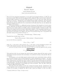
Recalling the classical thrust power required equation for an aircraft with a parabolic<br />
drag polar equipped with a reciprocating engine driving a propeller<br />
THP req = σρ SL<br />
2 fV 3 + 2 1 ( W<br />
σρ<br />
} {{ } SL πe b<br />
parasite<br />
) 2 1<br />
V<br />
} {{ }<br />
effective induced<br />
Multiplying by the true airspeed, V , yields<br />
THP req V = σρ SL<br />
2 fV 4 + 2 1 ( W ) 2<br />
= A + BV<br />
4<br />
(2)<br />
σρ SL πe b<br />
which is a linear relation in V 4 with<br />
A = 2 1 ( W ) 2<br />
and B = σρ SL<br />
σρ SL πe b<br />
2 f (3)<br />
Copyright c○2007-2009 David F. Rogers. All rights reserved. 4<br />
(1)
Hence, the aircraft equivalent parasite drag area † is given by the slope <strong>of</strong> the straight line.<br />
Specifically<br />
28<br />
.<br />
25 o , 7.670<br />
f = 2<br />
σρ SL<br />
B (4)<br />
<strong>Flap</strong> deflection δf , f<br />
THP reqstd TAS x 10 -6<br />
24<br />
20<br />
16<br />
32 o , 9.825<br />
o<br />
.<br />
o<br />
o<br />
o<br />
.<br />
.<br />
20 o , 5.669<br />
15 o , 4.677<br />
10 o , 3.636<br />
0 o , 3.125<br />
12<br />
8<br />
o<br />
E33A Bonanza<br />
Standard Sea Level<br />
.<br />
Gross Weight 3300 lbs<br />
0 1000 2000 3000 4000 5000<br />
TASstd<br />
4 x 10 -6<br />
Figure 2. Equivalent parasite drag area for various flap deflections.<br />
Figure 2 shows the data plotted as THP req std<br />
V against V 4 as suggested by Eq.(2). A<br />
linear least squares fit is also shown for each flap deflection. Clearly, the expected linear<br />
relation results. The increased slope for the aircraft with increasing flap deflection indicates<br />
increased parasite drag as expected. Table 1 shows the values for the slope, B, theR 2<br />
value and the value f obtained using Eq.(4). The results in Table 1 show that, as expected,<br />
increasing flap deflection increases the equivalent parasite drag area These are significant<br />
changes.<br />
The equivalent parasite drag area plotted against flap deflection is shown in Figure 3.<br />
The parabolic least squares fit to the data, also shown in Figure 3, clearly indicates that<br />
the equivalent parasite drag area varies parabolically with flap deflection.<br />
† The aircraft equivalent parasite drag area as used here is simply the classical parabolic drag polar constant<br />
term, i.e. the zero lift drag coefficient multiplied by the aircraft reference wing area.<br />
Copyright c○2007-2009 David F. Rogers. All rights reserved. 5
10<br />
8<br />
E33A Bonanza<br />
Standard Sea Level<br />
Gross Weight 3300 lbs<br />
<strong>Parasite</strong> drag area, f, (sq ft)<br />
6<br />
4<br />
2<br />
f = 0.0065δ 2 + 0.0812δ + 3.06<br />
R 2 f<br />
f<br />
= 0.994<br />
0<br />
0 5 10 15 20 25 30 35<br />
<strong>Flap</strong> deflection angle, δ f , (deg)<br />
Figure 3. Equivalent parasite drag area as a function <strong>of</strong> flap deflection angle, δ f .<br />
Table 1. Results for f, clean<br />
δ ◦ f B × 10 3 R 2 f(ft 2 ) ∆f(ft 2 )<br />
0 3.714 0.995 3.125 0.000<br />
10 4.321 0.991 3.636 0.511<br />
15 5.556 0.992 4.677 1.552<br />
20 6.737 0.998 5.669 2.544<br />
25 9.116 0.997 7.670 4.545<br />
32 11.676 0.996 9.825 6.700<br />
The parabolic variation <strong>of</strong> the equivalent parasite drag area with flap deflection suggests<br />
a linear variation with the square <strong>of</strong> the flap deflection. Figure 4 shows the equivalent<br />
parasite drag area for the flight test data plotted against the square <strong>of</strong> the flap deflection<br />
in radians, along with a linear least square fit to the data <strong>of</strong> Table 1.<br />
McCormick (Ref. 8 Table 4.2) gives the skin friction coefficient for a Model V-35 V-tail<br />
Bonanza as 0.0049. Eckalbar (Ref. 9) gives the wetted surface area based on an estimate by<br />
Stinson (Ref. 10) as 620 ft 2 for the V-35 and estimates that the wetted surface area <strong>of</strong> the<br />
conventional tailed Model E33A as 640 ft 2 . Using McCormick’s value for the skin friction<br />
coefficient and Eckalbar’s estimate for the wetted surface area yields an equivalent parasite<br />
drag area <strong>of</strong> 3.14 ft 2 , which agrees quite well with the current flight test result for δ f =0.<br />
A literature search revealed no similar flight test data for partial span partially deflected<br />
flaps. However, Wenziger and Harris (Ref. 1) present wind tunnel airfoil data for an NACA<br />
23012 airfoil equipped with a 0.2566 chord slotted flap, although they do not plot the data<br />
versus δf 2. Extracting the data from Wenzinger and Harris (Ref. 1, Figure 15) for C d 0<br />
at<br />
C l = 0 for flap deflections from zero to forty degrees and performing a linear least square<br />
Copyright c○2007-2009 David F. Rogers. All rights reserved. 6
fit, again yields a linear relation in the square <strong>of</strong> the flap deflection as shown in the inset<br />
in Figure 4. Data from Wenzinger and Harris for split, plain and Fowler flaps also yield a<br />
linear relation in the square <strong>of</strong> the flap deflection for similar flap deflection angles, although<br />
the slopes are, not surprisingly, different. This result suggests that two or three level flight<br />
performance tests with partially extended flaps will yield adequate data for estimating<br />
performance for modest flap deflections.<br />
0.3<br />
0.25<br />
0.2<br />
NACA 23012<br />
Airfoil TR-664<br />
Slotted flap 1b<br />
0.15<br />
Equivalent flap plate area ft 2<br />
13<br />
12<br />
11<br />
10<br />
9<br />
8<br />
7<br />
6<br />
5<br />
.<br />
4<br />
3<br />
0.1<br />
0.05<br />
f = 0.3234 δ 2 + 0.0272<br />
R 2 f<br />
= 0.9983<br />
0<br />
0 0.1 0.2 0.3 0.4 0.5 0.6 0.7<br />
+<br />
+<br />
f = 15.65 δ 2 + 7.880<br />
.<br />
.<br />
.<br />
R 2 f<br />
= 0.988<br />
.<br />
.<br />
f = 22.09 δ 2 + 3.125<br />
R 2 f<br />
= 0.994<br />
E33A Bonanza<br />
Standard Sea Level<br />
Gross Weight 3300 lbs<br />
0 0.05 0.1 0.15 0.20 0.25 0.30<br />
<strong>Flap</strong> deflection squared, δ 2<br />
f , radians 2<br />
Figure 4. Equivalent parasite drag area as a function <strong>of</strong> the square <strong>of</strong> the flap deflection angle, δ 2 f .<br />
Copyright c○2007-2009 David F. Rogers. All rights reserved. 7
Table 2. Results for f<br />
gear down cowl flaps open<br />
δ ◦ f B × 10 3 R 2 f(ft 2 ) ∆f(ft 2 )<br />
0 8.808 0.9897 7.593 4.286<br />
10 10.276 0.9711 8.646 5.521<br />
20 11.681 0.9995 9.829 6.522<br />
32 15.114 0.9932 12.717 9.592<br />
In order to test the suggestion above, four additional flight tests were conducted in<br />
the power approach configuration, i.e., gear down and cowl flaps open with various flap<br />
deflections. The results are shown in Table 2 and in Figure 4. The first flight test was<br />
conducted with gear down and a flap deflection <strong>of</strong> zero. The second flight test was conducted<br />
with gear down and a flap deflection <strong>of</strong> 32 ◦ . From these two results the equivalent parasite<br />
drag area for gear down and flap deflections <strong>of</strong> 10 ◦ and 20 ◦ were estimated as shown by<br />
the +s in Figure 4. <strong>Flight</strong> tests where then conducted in the power approach configuration<br />
with flap deflections <strong>of</strong> 10 ◦ and 20 ◦ . The results are shown by the squares in Figure 4. The<br />
flight test results are in good agreement with the estimates.<br />
Conclusions<br />
Level flight performance tests were conducted on a typical light general aviation single<br />
engine retractable aircraft to determine the equivalent parasite drag area <strong>of</strong> partially deflected<br />
partial span flaps. The equivalent parasite drag area in the gear up configuration<br />
increased by a factor <strong>of</strong> 1.16 for 10 ◦ and by a factor <strong>of</strong> 1.81 for 20 ◦ flap deflection angle. At<br />
a maximum deflection <strong>of</strong> 32 ◦ the aircraft equivalent parasite drag area increased by a factor<br />
<strong>of</strong> 3.14 compared to the aircraft value when the flaps were undeflected. Both a parabolic<br />
variation <strong>of</strong> the equivalent parasite drag area with flap deflection angle and a linear relation<br />
with the flap deflection angle squared were found. Additional flight tests in the gear down<br />
configuration confirmed the linear variation with flap deflection angle squared. Classical<br />
NACA wind tunnel data for an NACA 23012 airfoil equipped with a similar single slotted<br />
flap also resulted in both a parabolic variation <strong>of</strong> the equivalent parasite drag area with<br />
flap deflection angle and a linear relation with flap deflection angle squared. The results<br />
are expected to be similar for similar aircraft.<br />
References<br />
1. Wenzinger, C.J. and Harris, T.A., “Wind-tunnel Investigation <strong>of</strong> an N.A.C.A. 23012<br />
Airfoil with various arrangements <strong>of</strong> Slotted <strong>Flap</strong>s”, NACA Report 664, 1939.<br />
2. House, Rufus O., “The Effects <strong>of</strong> <strong>Partial</strong>-span Slotted <strong>Flap</strong>s on the Aerodynamic Characteristics<br />
<strong>of</strong> Rectangular and Tapered N.A.C.A. 23012 Wing.” NACA TN-719, 1939.<br />
3. Rogers, David F., “Comparative <strong>Flight</strong> Tests With and Without Tip Tanks”, AIAA J.<br />
<strong>of</strong> Aircraft, Vol. 44, No. 5, September–October 2007, pp. 1740–1744.<br />
4. Rogers, David F., “An Engineering <strong>Flight</strong> Test Course Emphasizing <strong>Flight</strong> Mechanics<br />
Concepts”, AIAA J. <strong>of</strong> Aircraft, Vol. 39, No. 1, January–February 2002, pp. 79–83.<br />
5. Teledyne Continental Motors, Aircraft Products Division, IO-520 Series, Operator’s<br />
Manual, Form No. X30041, September, 1980.<br />
Copyright c○2007-2009 David F. Rogers. All rights reserved. 8
6. Lewis, G., “A <strong>Flight</strong> Test Technique Using GPS for Position Error Correction Testing,”<br />
Cockpit, Quarterly <strong>of</strong> the Society <strong>of</strong> Experimental Test Pilots, Jan/Feb/March 1997,<br />
pp. 20–24.<br />
7. McCauley Accessory Division, The Cessna Aircraft Company, 3535 McCauley Drive,<br />
Vandalia, OH 45377.<br />
8. McCormick, B., Aerodynamics, Aeronautics and <strong>Flight</strong> Mechanics, John Wiley & Sons,<br />
New York, 1979.<br />
9. Eckalbar, J., Flying the Beech Bonanza, McCormick-Armstrong Co., Wichita, KS, 1986.<br />
10. Stinton, D., The Design <strong>of</strong> the Airplane, 2/e, AIAA, 2001.<br />
Copyright c○2007-2009 David F. Rogers. All rights reserved. 9