460984001C - UTCFS Global Security Products
460984001C - UTCFS Global Security Products
460984001C - UTCFS Global Security Products

You also want an ePaper? Increase the reach of your titles
YUMPU automatically turns print PDFs into web optimized ePapers that Google loves.
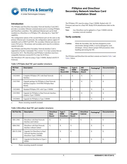
PXNplus and DirecDoor<br />
Secondary Network Interface Card<br />
Installation Sheet<br />
Introduction<br />
The PXNplus and DirecDoor Secondary Network Interface Card (NIC)<br />
provides a secondary Ethernet communications port to existing PXNplus<br />
and DirecDoor controllers. This additional Ethernet port can be field<br />
installed on a DirecDoor or a PXNplus CPU, allowing for a “dual NIC”<br />
capability.<br />
The configuration options of the second Ethernet port are the same as the<br />
primary Ethernet port. In particular, the configuration options support IT<br />
standards such as DHCP and NFS. The secondary Ethernet port does not<br />
source PoE power. The primary and secondary ports must be on distinct,<br />
separate networks.<br />
The PXNplus and DirecDoor Secondary Network Interface Card is<br />
supported on Facility Commander Wnx version 7.6 or later systems that are<br />
licensed for ACU. The DirecDoor and PXNplus Controllers must have<br />
compatible firmware (version R119 or later for FCWnx).<br />
The DirecDoor CPU must be using a Type-3 SIMM, flashed with R119<br />
Firmware.<br />
The PXNplus CPU must be using a Type-3 SIMM, flashed with 119<br />
Firmware and must be a Dual NIC Ready PCB (identification label on the<br />
board).<br />
Note:<br />
Any DirecDoor can be updated to a Type-3 SIMM with the<br />
secondary network installed.<br />
Verify contents<br />
Caution:<br />
While the Secondary NIC has been designed to resist<br />
electrostatic damage (ESD), it can be damaged by such<br />
discharges. Always observe proper ESD precautions when<br />
handling and storing the NIC.<br />
The PXNplus and DirecDoor kits and their contents are listed in Table 1 and<br />
Table 2 below.<br />
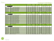
Table 1:PXNplus dual NIC part number structures<br />
Kit Part<br />
No.<br />
Description<br />
PXNplus<br />
Base<br />
Board-002<br />
Type-3<br />
SIMM<br />
PXNplus<br />
NIC<br />
Daughter<br />
Board<br />
Packaging a<br />
Documentation<br />
110216001 Complete PXNplus CPU with Dual Network<br />
Interface<br />
110217001 Upgrade package for PXNplus to Dual Network<br />
Interface (requires 110187002 PXNplus Base<br />
Board)<br />
X X X X X<br />
X X X X<br />
110218001 Standard PXNplus CPU with Type-3 SIMM X X X X<br />
110219001 Upgrade for PXNplus to Dual Network Interface<br />
(requires Type-3 SIMM)<br />
X X X<br />
110220001 Upgrade for PXNplus to Type-3 SIMM X X X<br />
a. Plastic mounting standoffs included<br />
Table 2:DirecDoor dual NIC part number structures<br />
Kit Part No. Description DirecDoor<br />
Base<br />
Board<br />
Type 3<br />
SIMM<br />
DirecDoor<br />
NIC<br />
Daughter<br />
Board<br />
DirecDoor<br />
Cabinet<br />
Packaging a<br />
Documentation<br />
DD1-2NIC<br />
DD0-2NIC<br />
DD-T3-2NIC<br />
DD-T3<br />
DirecDoor with Dual Network<br />
Interface and Cabinet<br />
DirecDoor with Dual Network<br />
Interface without Cabinet<br />
Upgrade For DirecDoor to Dual<br />
Network Interface (includes<br />
DirecDoor Type-3 SIMM)<br />
Upgrade for DirecDoor to Type-3<br />
SIMM<br />
X X X X X X<br />
X X X X X<br />
X X X X<br />
X X X<br />
a. Plastic mounting standoffs included<br />
1 <strong>460984001C</strong> ISS 07/24/12
Installation<br />
The PXNplus and DirecDoor Network Interface Card can be installed on a<br />
DirecDoor or a PXNplus CPU. The PXNplus PCB must be identified as<br />
“Dual NIC Ready.” See Figure 1.<br />
Note: Any DirecDoor can be updated to a Type-3 SIMM with the<br />
secondary network installed.<br />
Installing the NIC on a PXNplus CPU<br />
To install the NIC on a PXNplus CPU:<br />
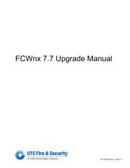
1. On the NIC, insert the plastic standoff into the hole adjacent to the<br />
RJ45 network connector J5 as shown in Figure 1 below.<br />
2. Remove the adhesive liner from the standoff, and then carefully line<br />
up and insert the connector pins on the bottom of the NIC with<br />
connector headers P1, P2, P3, and P4 on the PXNplus PCB.<br />
3. Make sure the adhesive back of the standoff is secured to the PXNplus<br />
PCB.<br />
4. Plug in the network cable to connector J5 on the NIC.<br />
Figure 1: PXNplus NIC Installation<br />
Installing the NIC on a DirecDoor CPU<br />
To install the NIC on a DirecDoor CPU:<br />
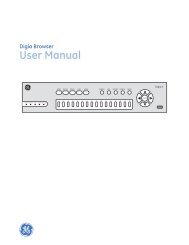
1. Remove, and then discard, the old plastic overlay from the DirecDoor<br />
PCB.<br />
2. On the NIC, insert the plastic standoff into the hole in front of the<br />
RJ45 network connector J5 as shown in Figure 2.<br />
3. Remove the adhesive liner from the standoff, and then carefully line<br />
up and insert the connector pins on the bottom of the NIC with<br />
connector headers P1, P2, P3, and P4 on the DirecDoor PCB.<br />
4. Make sure the adhesive back of the standoff is secured the DirecDoor<br />
PCB.<br />
5. Plug in the network cable to connector J5 on the NIC.<br />
6. Install the new plastic overlay on the DirecDoor PCB.<br />
7. If a Type-3 SIMM upgrade is required, remove the existing SIMM and<br />
install the new Type-3 SIMM.<br />
Setup<br />
Figure 2: DirecDoor Installation<br />
Perform the setup instructions in the following order:<br />
1. Configure the computer.<br />
2. Configure the NIC using the Integrated Configuration Tool (ICT).<br />
3. Configure the NIC in the Facility Commander Wnx (FCWnx)<br />
application.<br />
Configuring the computer<br />
Before you begin<br />
If there is a firewall on the computer you are using to access the Integrated<br />
Configuration Tool (ICT), you need to disable it in order to use the ICT.<br />
If your network is using a proxy, you need to disable the proxy or bypass it.<br />
First-time configuration<br />
By default, the controller's IP address is 192.168.6.6. To have your<br />
computer communicate with the controller, connect your computer to J1 on<br />
the PXNplus CPU board or J10 on the DirecDoor CPU board using a Cat5<br />
cable.<br />
Set the IP address to 192.168.6.5 or a similar valid IP address<br />
(192.168.6.x where x is any number between 1 and 254, except 6).<br />
Configuring the controller NIC using the ICT<br />
To configure the controller NIC using the Integrated Configuration Tool:<br />
1. Connect the computer to J1 on the PXNplus CPU board or J10 on the<br />
DirecDoor CPU board using a Cat5 cable.<br />
2. Power up the PXNplus or DirecDoor controller.<br />
3. Open your web browser, and then enter the IP address of the controller<br />
in the browser Address field.<br />
4. Enter your username and password on the password page. The default<br />
for both the username and password is install. We recommend<br />
that you change this default.<br />
5. The Integrated Configuration Tool main page opens as shown below.<br />
2 <strong>460984001C</strong> ISS 07/24/12
. Secondary Network tab<br />
Controller Information: Enter the Controller IP address. If<br />
required, enter the Gateway IP and Subnet IP addresses. Make<br />
sure that the secondary network controller IP address is different<br />
from the primary network controller IP address.<br />
6. On the Controller Configuration menu, click Host/Connection type,<br />
and then configure as follows.<br />
Host/Server Type: Select Facility Commander Wnx Licensed for<br />
ACU or Diamond / SapphirePro Systems<br />
Primary Connection Type: Select Ethernet<br />
7. Click Save.<br />
8. On the Controller Information menu, click Controller Information,<br />
and then configure as follows.<br />
Controller Address: (Example) Enter 1<br />
Host Service Port: Enter 6699<br />
Redundant Host Timeout: Enter 30<br />
11. Click Save.<br />
12. On the Administration menu, click Apply Changes, and then click<br />
Restart Application.<br />
Configuring the controller NIC in Facility<br />
Commander Wnx<br />
To configure the controller NIC in Facility Commander Wnx:<br />
1. In the Facility Commander Wnx application, Application Group<br />
pane, click <strong>Security</strong> Devices, and then click Controller.<br />
2. On the Controller Definition tab, Connection type, select<br />
Network + Network.<br />
3. On the Port Settings tab, in the Network Configuration area, enter the<br />
IP addresses for the Primary Network and Secondary Network.<br />
9. Click Save.<br />
10. On the Controller Parameters menu, click Network Configuration,<br />
and then configure as follows.<br />
Note: The secondary IP address must be on a different network<br />
(Example: primary address: 192.168.6.X and secondary address:<br />
192.168.7.X). For gateway and subnet information, contact your<br />
local IT administrator.<br />
a. Primary Network tab<br />
Enable Secondary: Check the Enable Secondary check box<br />
(this enables the Secondary Network tab).<br />
Controller Information: Enter the Controller IP address. If<br />
required, enter the Gateway IP and Subnet IP addresses.<br />
3 <strong>460984001C</strong> ISS 07/24/12
Regulatory Information<br />
Certification<br />
N4131<br />
Contacting Technical Support<br />
For assistance with this product, refer to this document and any other<br />
documentation provided. If you still have questions, you may contact<br />
technical support during normal business hours (Monday through Friday,<br />
excluding holidays, between 8 a.m. and 7 p.m. Eastern Time).<br />
FCC compliance<br />
Environmental<br />
class<br />
European Union<br />
directives<br />
This equipment has been tested and found to comply<br />
with the limits for a Class A digital device, pursuant to<br />
part 15 of the FCC Rules. These limits are designed to<br />
provide reasonable protection against harmful<br />
interference when the equipment is operated in a<br />
commercial environment. This equipment generates,<br />
uses, and can radiate radio frequency energy and, if not<br />
installed and used in accordance with the instruction<br />
manual, may cause harmful interference to radio<br />
communications.<br />
Indoor dry<br />
2002/96/EC (WEEE directive): <strong>Products</strong> marked with<br />
this symbol cannot be disposed of as unsorted<br />
municipal waste in the European Union. For proper<br />
recycling, return this product to your local supplier<br />
upon the purchase of equivalent new equipment, or<br />
dispose of it at designated collection points. For more<br />
information see: www.recyclethis.info.<br />
Region Telephone Fax<br />
North America 855 536 3573 561 998 6224<br />
Asia 65 6424 7932 65 6424 7978<br />
Australia 61 3 9239 1200 61 3 9239 1299<br />
Canada 800 267 6317 613 737 5517<br />
EMEA 48 58 326 22 40 48 58 326 22 41<br />
Latin America 503 589 8614 561 994 6572<br />
Email: rs-bctsupport@fs.utc.com<br />
Web site: www.utcfireandsecurity.com<br />
© 2012 UTC Fire & <strong>Security</strong>. All Rights Reserved.<br />
4 <strong>460984001C</strong> ISS 07/24/12