d7600_im - UTCFS Global Security Products
d7600_im - UTCFS Global Security Products
d7600_im - UTCFS Global Security Products

You also want an ePaper? Increase the reach of your titles
YUMPU automatically turns print PDFs into web optimized ePapers that Google loves.
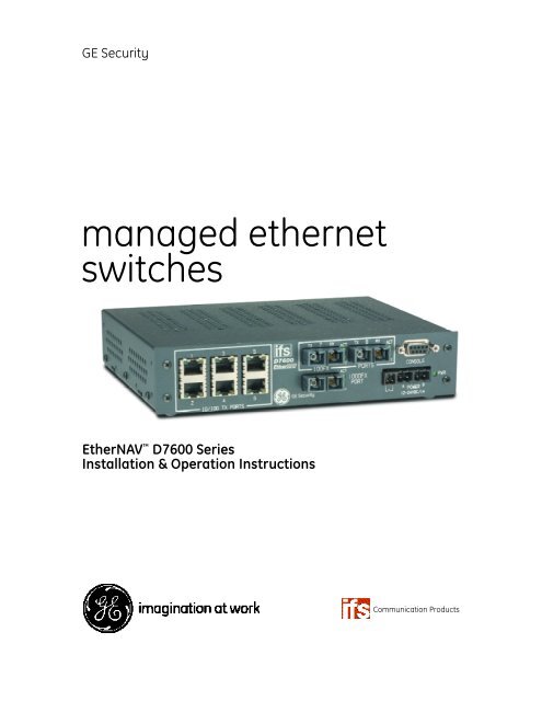
GE <strong>Security</strong><br />
managed ethernet<br />
switches<br />
EtherNAV D7600 Series<br />
Installation & Operation Instructions<br />
Communication <strong>Products</strong>
Manageable 8/9-Port Switch<br />
PREFACE<br />
This manual describes how to install and use the D7600 series EtherNav”<br />
Manageable 8/9-Port 10/100/1000 Base-TX (100/1000 Base-FX) Ethernet Switch.<br />
This switch integrates full wire speed switching technology with SNMP/RMON<br />
web-based management functions. The D7600 series brings a s<strong>im</strong>ple answer to<br />
today’s complicated networking environments.<br />
To get the most out of this manual, you should have an understanding of Ethernet<br />
networking concepts.<br />
In this manual, you will find:<br />
• Features on the Switch<br />
• Illustrative LED functions<br />
• Installation Instructions<br />
• Management Configuration<br />
• SNMP…<br />
• Specifications<br />
User’s Manual
Manageable 8/9-Port Switch<br />
INSTALLATION & OPERATION MANUAL / IFS D7600<br />
PREFACE<br />
TABLE OF CONTENTS<br />
PRODUCT OVERVIEW<br />
Package Contents............................................................................................................................................ 1<br />
Product Features............................................................................................................................ 1<br />
Basic Features................................................................................................................ 1<br />
Management Support................................................................................................ 2<br />
Front Panel Display....................................................................................................................... 3<br />
Physical Ports................................................................................................................................... 4<br />
Basic Functions............................................................................................................................... 5<br />
Unicast Switching......................................................................................................... 5<br />
Multicast Switching...................................................................................................... 7<br />
VLAN..................................................................................................................................................... 8<br />
Broadcast Containment............................................................................................ 9<br />
Multi-Based Mult<strong>im</strong>edia Applications.................................................................. 9<br />
Enhanced <strong>Security</strong>....................................................................................................... 9<br />
VLAN Membership........................................................................................................ 9<br />
VLAN Configuration..................................................................................................... 10<br />
Intra-VLAN Communication..................................................................................... 10<br />
Inter-VLAN Communication..................................................................................... 10<br />
GVRP...................................................................................................................................................... 10<br />
IGMP Snooping and IP Multicast Filtering........................................................................... 10<br />
Switch Management..................................................................................................................... 11<br />
INSTALLATION............................................................................................................................................. 12<br />
Selecting A Site For The Switch................................................................................................ 12<br />
Methods for Mounting the D7600........................................................................................... 12-15<br />
Connecting To Power.................................................................................................................... 16<br />
Power-On Self Test (POST)......................................................................................... 16<br />
Connecting To Your Network.................................................................................................... 17<br />
Cable Type & Length................................................................................................... 17<br />
SWITCH MANAGEMENT...................................................................................................................... 18<br />
Management Access Overview............................................................................................... 18-19<br />
Administration Console................................................................................................................ 20<br />
Direct Access................................................................................................................... 20<br />
Web Management......................................................................................................................... 21<br />
Netscape Navigator..................................................................................................... 21<br />
Internet Explorer............................................................................................................ 21<br />
User’s Manual
Manageable 8/9-Port Switch<br />
INSTALLATION & OPERATION MANUAL / IFS D7600<br />
SWITCH MANAGEMENT CONTINUED….<br />
SNMP-Based Network Management................................................................................... 22<br />
Protocols............................................................................................................................................. 22<br />
Management Architecture........................................................................................................ 22<br />
MENU-DRIVEN CONSOLE MANAGEMENT......................................................................... 23<br />
Logging On To The Switch......................................................................................................... 23<br />
At The Screen Prompt................................................................................................ 23<br />
Switch Management Screen..................................................................................................... 24<br />
Navigating Through The Console Interface...................................................... 25<br />
Performing Basic Management Activities.......................................................................... 25-31<br />
Alarm Configurations................................................................................................. 32<br />
Performing Advanced Management Activities................................................................. 33-62<br />
Sending and Receiving Files..................................................................................................... 63-64<br />
Logout................................................................................................................................................. 65<br />
Save Settings.................................................................................................................................... 65<br />
Restore Default Settings............................................................................................................. 65<br />
Reboot................................................................................................................................................. 65<br />
WEB-BASED BROWSER MANAGEMENT.............................................................................. 66<br />
Logging On To The Switch......................................................................................................... 66<br />
Understanding The Browser Interface................................................................................ 67<br />
Performing File Activities............................................................................................................ 68<br />
To Perform File Activities........................................................................................... 68<br />
Performing Basic Setup Activities.......................................................................................... 69<br />
To Perform Basic Setup Activities......................................................................... 69-73<br />
Performing Advanced Setup Activities................................................................................. 74<br />
To Perform Advanced Setup Activities................................................................ 74-86<br />
SNMP & RMON MANAGEMENT.................................................................................................... 87<br />
Overview............................................................................................................................................. 87<br />
SNMP Agent and MIB (RFC 1213)............................................................................................ 87<br />
RMON Groups Supported......................................................................................... 88<br />
Bridge Groups Supported......................................................................................... 89<br />
SPECIFICATIONS........................................................................................................................................ 90<br />
APPENDIX A – CONNECTOR PINOUTS.................................................................................. 91<br />
D7600 Front Panel Layouts........................................................................................................... 92-93<br />
User’s Manual
Manageable 8/9-Port Switch<br />
PRODUCT OVERVIEW<br />
Manageable 8/9-Port Switch<br />
100FX Optical Ports<br />
Console Port<br />
10/100TX Electrical Ports<br />
Front View (D7600-MM-E-CC shown)<br />
10/100/1000TX Port<br />
Power Ports<br />
Fiber Loss Alarm<br />
PACKAGE CONTENTS<br />
When you unpack the product package, you shall find the items listed below.<br />
• D7600 EtherNav” Management Switch<br />
• D7600 Quick Start Guide<br />
• External Power Adapter<br />
• CD ROM<br />
PRODUCT FEATURES<br />
Basic Features:<br />
- Provides up to nine (10/100/1000TX and/or 100/1000FX combination) ports<br />
- Mult<strong>im</strong>ode fiber using SC connectors up to 2 km; singlemode fiber using<br />
SC connectors up to 15 km for 100FX, 10km for 1000FX<br />
- Auto-negotiation for speed and duplicity on all TX ports<br />
- Store-and-Forward mechanism<br />
- Back-pressure and IEEE 802.3x compliant flow control<br />
- Supports 4K MAC addresses<br />
- Redundant power supply connections<br />
- Optional TX or FX 1000Mbps aggregation port<br />
- Optional contact closure for fiber loss alarm<br />
User’s Manual 1
Manageable 8/9-Port Switch<br />
PRODUCT FEATURES CONTINUED...<br />
Management Support:<br />
VLAN<br />
- 802.1Q tagged VLAN (up to 64 VLANs)<br />
- Quality of Service (QoS)<br />
Link Aggregation<br />
- Port-based Aggregation, up to four groups with a max<strong>im</strong>um<br />
of four ports each group<br />
- Load sharing based on source and destination MAC addresses<br />
Port-Mirroring<br />
- Port-mirroring provided through dedicated port, Port 1<br />
Internet Working Protocols:<br />
Bridging<br />
- 802.1D Spanning Tree<br />
- 802.1P/Q –GARP/GVRP<br />
IP Multicast<br />
- IP Multicast Packet Filtering<br />
Network Management Methods:<br />
- Console port access via RS-232 cable<br />
- Telnet remote access<br />
- SNMP Agent:<br />
• MIB-2 (RFC1213)<br />
• Bridge MIB (RFC1493)<br />
• RMON MIB (RFC1757)-statistics, history, alarm & events<br />
• VLAN MIB (802.1Q/RFC2674)<br />
• Private MIB<br />
- Web browser support based on HTTP server and CGI parser<br />
- TFTP/Web software-upgrade capability<br />
User’s Manual 2
Manageable 8/9-Port Switch<br />
FRONT PANEL DISPLAY<br />
(D7600-MM-E-CC Shown)<br />
10/100TX Port Status<br />
Optical Status 10/100/1000TX Port Status Power Indicator<br />
1. Power Indicator<br />
This LED comes on when the switch is properly connected to power.<br />
2. Optical Status LED’s (FX)<br />
The ACT LED’s come on when data is present.<br />
(LED will flash at the rate data is transferred).<br />
The LNK LED’s will be on for 100FX speed transmission.<br />
3. 10/100/1000TX Port Status LED’s<br />
The LED’s are located at each port, displaying status.<br />
Please refer to the Table for more details.<br />
User’s Manual 3
Manageable 8/9-Port Switch<br />
LED State Indication<br />
GREEN<br />
Steady<br />
A valid network connection established<br />
YELLOW<br />
Flashing<br />
Data transfer<br />
PHYSICAL PORTS<br />
This EtherNav” managed switch provides up to nine (10/100/1000TX and/or 100/1000FX<br />
combinations) ports:<br />
CONNECTIVITY<br />
- RJ-45 connectors<br />
- SC connector on fiber ports<br />
MODE SELECTION<br />
- 10BaseT full-duplex mode<br />
- 10BaseT half-duplex mode<br />
- 100BaseTX full-duplex mode<br />
- 100BaseTX half-duplex mode<br />
- 100BaseFX full-duplex mode<br />
- 100BaseFX half-duplex mode<br />
- 1000BaseTX full-duplex mode<br />
- 1000BaseTX half-duplex mode<br />
- 1000BaseFX full-duplex mode<br />
- 1000BaseFX half-duplex mode<br />
- Auto-sensing mode except 100FX<br />
User’s Manual 4
Manageable 8/9-Port Switch<br />
PLEASE NOTE:<br />
I. Half-duplex mode uses back pressure flow control to prevent the receiving<br />
buffer from being overrun by data from a source node.<br />
II. Full-duplex mode uses 802.3x flow control standard to prevent fast data traffic<br />
from overrunning slow data traffic.<br />
III. Auto-sensing mode is in use after auto-negotiating with the other end of the link.<br />
BASIC FUNCTIONS<br />
In general, the D7600 is responsible for switching both VLAN tagged and untagged frames<br />
from a receiving port to one or more transmitting ports. The switch performs multiple steps<br />
during the switching process:<br />
VLAN CLASSIFICATION<br />
LEARNING<br />
FILTERING<br />
AGING<br />
Below is additional information about tasks that the switch performs during unicast<br />
and multicast switching.<br />
UNICAST SWITCHING<br />
VLAN CLASSIFICATION<br />
When the switch receives a frame, it classifies the frame in one of two ways:<br />
- If the frame is untagged, the switch classifies the frame to an<br />
associated VLAN.<br />
- If the frame is tagged, the switch uses the tagged VLAN ID to identify the<br />
broadcasting domain of the frame.<br />
User’s Manual 5
PLEASE NOTE:<br />
Manageable 8/9-Port Switch<br />
I. Half-duplex mode uses back pressure flow control to prevent the receiving<br />
buffer from being overrun by data from a source node.<br />
II. Full-duplex mode uses 802.3x flow control standard to prevent fast data traffic<br />
from overrunning slow data traffic.<br />
III. Auto-sensing mode is in use after auto-negotiating with the other end of the link.<br />
LEARNING<br />
After VLAN classification, the switch checks the pair in the<br />
switching database (SDB) to see whether the pair is known.<br />
- If it is unknown, the switch inserts the into the SDB<br />
and learns the .<br />
- If it is known, the switch checks the for a mis<br />
matched port ID. If the port ID associated with the <br />
pair in the SDB is different than the receiving port, the switch modifies the port ID<br />
in the SDB and modifies its management database (MDB) accordingly.<br />
FILTERING<br />
After learning the address, the switch checks:<br />
- Whether the source port or destination port is in the forwarding state.<br />
- Whether the source MAC address or destination MAC address is to be filtered.<br />
- Whether the source port ID is the same as destination port ID.<br />
If any of these conditions are met, the switch drops the receiving.<br />
Otherwise, it continues with the forwarding process described below.<br />
FORWARDING<br />
During the forwarding process, the switch checks whether the pair is unknown.<br />
- If it is unknown, the switch floods the receiving frame to all ports in the VLAN,<br />
excluding the source port.<br />
- If it is known, the switch forwards the receiving frame to the port associated<br />
with the pair. At the same t<strong>im</strong>e, the switch<br />
ascertains the individual’s ports VLAN tagging and/or un-tagging configuration<br />
and corresponding VLAN ID render the appropriate frame tagging when the frame<br />
is ready to be transmitted.<br />
User’s Manual 6
Manageable 8/9-Port Switch<br />
MULTICAST SWITCHING<br />
For multicast switching, the D7600 checks whether the received frame is a BPDU. If a BPDU<br />
is received, the switch forwards the frame to the CPU for processing by the spanning tree<br />
protocol. Otherwise, the D7600 performs the following processes:<br />
VLAN CLASSIFICATION<br />
Same as for unicast switching.<br />
LEARNING<br />
Same as for unicast switching.<br />
FILTERING<br />
After learning the address, the switch checks:<br />
- Whether the source port or destination port is not in the following state.<br />
- Whether the source MAC address or destination MAC address is to be filtered.<br />
If any of these conditions are met, the switch drops the receiving.<br />
Otherwise, it continues with the forwarding process described below.<br />
FORWARDING<br />
The D7600 floods the received multicast frame to all ports that are in the forwarding<br />
state within the VLAN, excluding the source port. At the same t<strong>im</strong>e, the switch<br />
ascertains the individual ports VLAN tagging/untagging configuration and<br />
corresponding VLAN to render the appropriate frame tagging when the frame is<br />
ready to be transmitted.<br />
AGING<br />
The switch performs the aging process for the pair in the<br />
switching database. Once a pair is aged out, the SBD is modified.<br />
SPANNING TREE<br />
The D7600 supports one Spanning Tree per bridged network.<br />
User’s Manual 7
Manageable 8/9-Port Switch<br />
VLAN<br />
A virtual LAN (VLAN) is a network of computers or peripherals that behave as if they are<br />
connected to the same wire, even though they may actually be physically located<br />
in different locations of a LAN. VLANs are s<strong>im</strong>ilar to a group of end stations, perhaps on<br />
multiple physical LAN segments that are not inhibited by their physical location<br />
and can communicate as if they were on a common LAN.<br />
VLANs are configured through software rather than hardware, which makes the<br />
extremely flexible. One of the biggest advantages of VLANs is that when a peripheral<br />
is physically moved to another location, it can stay on the same VLAN without any<br />
hardware reconfiguration.<br />
Because VLANs are not l<strong>im</strong>ited by the hardware constraints that physically connect<br />
traditional LAN segments to a network, they can define a network into various logical<br />
configurations. For example, VLANs can define a network by function.<br />
In this setting, a system integrator might create one VLAN for mult<strong>im</strong>edia users<br />
and another for email users. VLANs can also define a network by location or type<br />
of service. For example, a location might have one VLAN for its cameras, another<br />
for it access control, and another for its roadside signs.<br />
VLANs can also be set up according to the organization structure within a company.<br />
For example, the company president might have his/her own VLAN, the executive<br />
staff might have a different VLAN, and the remaining employees might have yet another<br />
different VLAN.<br />
As these examples show, VLANs offer matchless flexibility. The following sections describe<br />
how deploying VLANs can benefit system integrators and reduce design costs.<br />
User’s Manual 8
BROADCAST CONTROL<br />
In traditional networks, traffic broadcasts to all network devices, whether they are the intended<br />
recipients or not. However, VLANs can be set up to contain only those devices that need to<br />
communicate with each other. As a result, VLANs considerably reduce network congestion.<br />
In addition, VLANs prevent broadcast storms from causing a network from crashing due<br />
to volumes of traffic.<br />
MULTICAST-BASED MULTIMEDIA APPLICATIONS<br />
Mult<strong>im</strong>edia applications, such as interactive training, video monitoring, and video/data<br />
transmissions, require large amounts of bandwidth. These applications are also extremely<br />
sensitive to variable delays, which are inevitable on a shared Ethernet network. By defining a<br />
VLAN based on the IP multicast address for all defined members on the VLAN, adequate<br />
bandwidth will be available for these applications, providing true mult<strong>im</strong>edia Ethernet.<br />
IMPROVED SECURITY<br />
Because VLANs are independent, only the devices within the same VLAN can<br />
communicate with each other. If a device in one VLAN wants to communicate with<br />
a device in another VLAN, the traffic must go through a router.<br />
VLAN MEMBERSHIP<br />
VLAN <strong>im</strong>plementation allows:<br />
- Up to 64 VLANs in one switch.<br />
- VLANs across multiple switches by using explicit or <strong>im</strong>plicit tagging and the<br />
GARP/GVRP protocol defined in IEEE802.1p and 802.1Q.<br />
- An end station’s network interface card belongs to multiple VLANs.<br />
-A switch port to be associated with multiple VLANs.<br />
Manageable 8/9-Port Switch<br />
DEFINITIONS OF VLAN MEMBERSHIP<br />
VLAN <strong>im</strong>plementation allows VLAN membership to be defined based on ports. Physical port<br />
numbers organizes port-based VLANs. For example, switch ports 1,2,4 and 6 can be grouped<br />
on VLAN, while server ports 3,5,7 and 8 can be on another VLAN. Broadcasts from servers<br />
within each group would only go to the members of its own VLAN. This ensures that broadcast<br />
storms cannot cause a network to crash due to volumes of traffic.<br />
VLAN MEMBERSHIP LEARNING<br />
Port-based VLAN is defined using a static binding between a VLAN and its associated ports.<br />
The switch’s forwarding decision is based on the destination MAC address and<br />
its associated port ID. Therefore, to make valid forwarding and flooding decisions, the switch<br />
learns the relationship of the MAC address to its related port…and thus to the VLAN…at runt<strong>im</strong>e.<br />
User’s Manual 9
Manageable 8/9-Port Switch<br />
REMOTE VLAN MEMBERSHIP<br />
Additionally to providing network management tools that allow network administrators to<br />
statically add and delete VLAN member ports, the switch also supports GVRP (GARP VLAN<br />
Registration Protocol). GVRP allows for dynamic registration of VLAN port members within<br />
switch and across multiple switches.<br />
Other than supporting dynamic updating of registration entries in a switch, GVRP is<br />
used to communicate VLAN registration information to other VLAN-aware switches,<br />
so that a VLAN member can cover a wide span of switches on a network.<br />
GVRP allows both VLAN-aware workstations and switches to issue and revoke VLAN<br />
memberships. VLAN-aware switches register a propagate VLAN membership to all<br />
ports that belong to the active topology of the VLAN.<br />
VLAN CONFIGURATION<br />
The switch provides a Local/Remote Management Console Interface for VLAN<br />
configuration and management. An SNMP-based VLAN MIB is also provided.<br />
INTRA-VLAN COMMUNICATION<br />
The switch supports intra-VLAN communication through hardware as described in<br />
"Basic Functions" section.<br />
INTER-VLAN COMMUNICATION<br />
The switch supports Inter-VLAN communication using CPU-based routing software.<br />
GVRP (GARP VLAN Registration Protocol)<br />
In addition to network management tools that allow network administrators to statically<br />
add and delete VLAN member ports, the routing switch supports GARP VLAN Registration<br />
Protocol (GVRP). GVRP supports dynamic registration of VLAN port members within a switch<br />
and across multiple switches.<br />
In addition to dynamically updating registration entries with a switch, GVRP is used to<br />
communicate VLAN registration information to other VLAN-aware switches, so that<br />
members of a VLAN can cover a wide span of switches on a network.<br />
GVRP allows both VLAN-aware workstations and switches to issue and revoke VLAN<br />
memberships. VLAN-aware switches register and propagate VLAN membership to all<br />
ports that are part of the active topology of the VLAN.<br />
IGMP SNOOPING AND IP MULTICAST FILTERING<br />
The Internet Group Management Protocol (IGMP) runs between hosts and their <strong>im</strong>mediately<br />
neighboring multicast routers. The protocol’s mechanisms allow a host to inform its local<br />
router that it wants to receive transmissions addressed to a specific multicast group.<br />
Routers periodically query the LAN to determine if known group members are still active.<br />
User’s Manual 10
IGMP Snooping & IP Multicast Filtering Continued...<br />
Manageable 8/9-Port Switch<br />
If there is more than one router on the LAN performing IP multicasting, one of the routers is<br />
elected ‘querier’ and assumes the reponsibility.<br />
Based on the group membership information learned from the IGMP, a router can<br />
determine which (if any) multicast traffic needs to be forwarded to each of its ‘leaf’<br />
sub-networks. Multicast routers use this information, along with a multicast routing<br />
protocol, to support IP multicasting across the Internet.<br />
Routing switches support IP Multicast Filtering by:<br />
- Passively snooping on the IGMP Query and IGMP Report packets transferred<br />
between IP Multicast Routers and IP Multicast host groups to learn about IP<br />
Multicast group members, and<br />
- Actively sending IGMP Query messages to solicit IP Multicast group members.<br />
The purpose of IP multicast filtering is to opt<strong>im</strong>ize a switched network’s performance, so<br />
multicast packets will only be forwarded to those ports containing multicast group hosts<br />
members and routers instead of flooding to all ports in the subnet (VLAN).<br />
Routing switches with IP multicast filtering/switching capability not only run passively<br />
monitor IGMP Query and Report messages, DVMRP Probe messages, PIM, and MOSPF Hello<br />
messages; they also actively send IGMP Query messages to learn locations of multicast<br />
routers and member hosts in multicast groups within each VLAN.<br />
Note, however, IGMP neither alters nor routes any IP multicast packets. Since IGMP<br />
is not concerned with the delivery of IP multicast packets across sub-networks, an<br />
external IP multicast router is needed if IP multicast packets have to be routed<br />
across different sub-networks.<br />
SWITCH MANAGEMENT<br />
Administration Console Via RS-232 Console Port:<br />
The switch provides an on board serial port, which allows the switch to be configured via a<br />
directly connected terminal or a Telnet session.<br />
Web-Based Browser Interface:<br />
The switch also boasts a point-and-click browser-based interface that lets users access full<br />
switch configuration and functionality from a Netscape or Internet Explorer browser.<br />
External SNMP-Based Network Management:<br />
The switch can also be configured via SNMP.<br />
For more information on switch management, please refer to the "Switch Management" section.<br />
User’s Manual 11
Manageable 8/9-Port Switch<br />
INSTALLATION<br />
This section gives step-by-step instructions about how to install<br />
the EtherNav” D7600 switch:<br />
Selecting a Site for the Switch<br />
As with any electric device, you should place the switch where it will not be subjected to<br />
temperatures, humidity, or electromagnetic interference above the rated specifications.<br />
The site you select should meet the following requirements:<br />
- The ambient temperature should be between –40 to 74 degrees Celsius.<br />
- The relative humidity should be less than 95 percent, non-condensing.<br />
- Surrounding electrical devices should not exceed the electromagnetic field<br />
(RFC) standards for EIC 801-3, Level 2 (3V/M) field strength.<br />
- Make sure that the switch receives adequate ventilation. Avoid blocking the<br />
ventilation holes on all sides of the switch.<br />
Methods for Mounting the D7600<br />
Several mounting configurations are available for the variety of applications for which this<br />
switch was designed. Each configuration is described as follows:<br />
Wall or Floor Mounting (-W Option)<br />
The brackets provided will require the removal and re-installation of the cover screws as<br />
shown below.<br />
Bracket<br />
(-W Option)<br />
Cover Screws<br />
Note: Insure that all screw are re-installed for adequate stability in mounting. 12<br />
User’s Manual
Manageable 8/9-Port Switch<br />
DIN Rail Back Mounting (-DB Option)<br />
The bracket provided will require the removal and re-installation of some cover screws as<br />
shown below.<br />
Bracket<br />
(-DB Option)<br />
Cover Screws<br />
DIN Rail Side Mounting (-DS Option)<br />
The bracket provided will require the removal and re-installation of one cover screw, the other<br />
screws are provided with the bracket as shown below.<br />
D7600 Unit<br />
(10/100 Port Side)<br />
Provided Mounting<br />
Screws<br />
Bracket<br />
(-DS Option)<br />
Note: Bracket is mounted on the Power<br />
Supply Side (Right Side) of the switch.<br />
Cover Screw<br />
User’s Manual 13
Manageable 8/9-Port Switch<br />
Rack Mounting Single Unit (-RS Option)<br />
The brackets provided have screws included for proper mounting as shown below.<br />
Mounting Screws<br />
4 Locations (Provided)<br />
Brackets (-RS Option)<br />
(Top View)<br />
(Front View)<br />
Note: All screws must be fastened and secured to insure adequate stability and strength.<br />
User’s Manual 14
Rack Mounting Dual Units (-RD Option)<br />
The brackets and braces provided have screws included for proper<br />
mounting as shown below.<br />
Manageable 8/9-Port Switch<br />
(Front View)<br />
Brackets (2 Provided)<br />
Brace (2 Provided )<br />
Mounting<br />
Screws<br />
Brace<br />
Locations<br />
(Bottom View)<br />
User’s Manual 15
Manageable 8/9-Port Switch<br />
CONNECTING TO POWER<br />
External Power<br />
Step One: Wire the supplied AC power adapter to the “A” receptacle plug<br />
at the front of the switch. — white stripe to pin 1 (+), black to pin 2 (-).<br />
Step Two: Attach the plug into a standard AC outlet with the appropriate AC voltage.<br />
Pr<strong>im</strong>ary “A” Power Connector<br />
Secondary “B” Power Connector<br />
To Pr<strong>im</strong>ary Wall Supply<br />
To Secondary Supply<br />
(D7600-MM-E-CC Shown))<br />
Note: The secondary supply must be equal to or less than the potential of the pr<strong>im</strong>ary supply.<br />
Power On Self Test (POST)<br />
The switch performs its Power-On Self Test (POST) when the power is applied to the switch.<br />
During the POST, the switch CPU will:<br />
- Perform a series of diagnostic procedures to make sure the<br />
basic system is functioning properly<br />
- Decompresses the main switching software runt<strong>im</strong>e <strong>im</strong>age from<br />
the flash ROM into the DRAM area<br />
User’s Manual 16
Manageable 8/9-Port Switch<br />
CONNECTING TO YOUR NETWORK<br />
Cable Type & Length<br />
Wire the supplied AC power adapter to the “A” receptacle plug<br />
at the front of the switch. — white stripe to pin 1 (+), black to pin 2 (-).<br />
Step Two: Attach the plug into a standard AC outlet with the appropriate AC voltage.<br />
It is necessary to follow the cable specifications below when connecting the switch to your<br />
network. Use appropriate cables that meet your speed and cabling requirements.<br />
Table 3: Cable Specifications<br />
Speed Connector Port Speed<br />
Half /Full Duplex<br />
Cable<br />
Max. Distance<br />
10BaseT RJ-45 10/20 Mbps 2-Pair UTP/STP 100 m<br />
Cat. 5, 5E, 6<br />
10BaseTX<br />
1000BaseTX<br />
RJ-45<br />
100/200 Mbps 2-Pair UTP/STP<br />
Cat. 5, 5E, 6<br />
100 m<br />
100BaseFX SC 100/200 Mbps MMF (50 or 62.5µm) 2 km<br />
-25dB Return<br />
Loss Min<strong>im</strong>um<br />
100BaseFX<br />
100BaseFX-HP<br />
100BaseFX-HP1<br />
SC<br />
100/200 Mbps SMF (9 or 10µm)<br />
-25dB Return<br />
Loss Min<strong>im</strong>um<br />
37 km<br />
54 km<br />
97 km<br />
1000BaseFX SC 500/1000 Mbps SMF (9 or 10µm) 28 km<br />
-25dB Return<br />
Loss Min<strong>im</strong>um<br />
Cabling:<br />
Step 1:<br />
Step 2:<br />
Step 3:<br />
Step 4:<br />
Step 5:<br />
First, ensure the power of the switch and end devices are turned off.<br />
NOTE: Always ensure that the power is off before any installation.<br />
Prepare cable with corresponding connectors for each type of port in use.<br />
Consult Table 3 in previous section for cabling requirements based on<br />
connectors and speed.<br />
Connect one end of the cable to the switch and the other end to a<br />
desired device.<br />
Once the connections between two end devices are made successfully,<br />
turn on the power and the switch is operational.<br />
User’s Manual 17
Manageable 8/9-Port Switch<br />
SWITCH MANAGEMENT<br />
This section explains the methods that you can use to configure management access to<br />
the switch. It describes the types of management applications and the communication<br />
and management protocols that deliver data between your management device<br />
(workstation or personal computer) and the system. It also contains information about<br />
port connection options.<br />
This section covers the following topics:<br />
• Management Access Overview<br />
• Key Concepts<br />
• Key Guidelines for Implementation<br />
• Administration Console / Telnet Access<br />
• Web Management Access<br />
• SNMP Access<br />
• Standards, Protocols, and Related Reading<br />
MANAGEMENT ACCESS OVERVIEW<br />
The EtherNav” D7600 switch gives you the flexibility to access and manage the switch<br />
using any or all of the following methods.<br />
The administration console and web browser interface support are embedded in the switch<br />
and are available for <strong>im</strong>mediate use.<br />
User’s Manual 18
Manageable 8/9-Port Switch<br />
Administration Console via RS-232 Console Port:<br />
Advantages:<br />
- No IP address or subnet needed<br />
- Text-based<br />
- HyperTerminal built into Windows 95/98/NT/2000<br />
operating systems<br />
Disadvantages:<br />
- Must be near switch<br />
- Inconvenient for remote users<br />
Web-Based Browser Interface:<br />
Advantages:<br />
- Ideal for configuring the switch remotely<br />
- Compatible with all popular browsers<br />
- Can be accessed from any location<br />
- Most visually appealing<br />
Disadvantages:<br />
- <strong>Security</strong> can be compromised (hackers need only know the IP address<br />
and subnet mask)<br />
- May encounter lag t<strong>im</strong>es on poor connections<br />
Telnet Interface:<br />
The connection is the same as Web-Based Browser Interface, but with Console<br />
Port Hyper Terminal type user interface.<br />
External SNMP-Based Network Management Application:<br />
Advantages:<br />
- Communicates with functions at the MIB level<br />
- Based on open standards<br />
Disadvantages:<br />
- Requires SNMP manager software<br />
- Least visually appealing of all three methods<br />
- Some settings require calculations<br />
- <strong>Security</strong> can be compromised (hackers need only know the community name)<br />
User’s Manual 19
Manageable 8/9-Port Switch<br />
ADMINISTRATION CONSOLE<br />
The administration console is an external, character-oriented, menu-driven user<br />
interface for performing system administration such as displaying statistics or<br />
changing option settings.<br />
Using this method, you can view the administration console from a terminal, personal<br />
computer, Apple Macintosh, or workstation connected to the switch’s console port.<br />
There are two ways to use this management method: direct access or mode Telnet access.<br />
The following sections describe these methods:<br />
DIRECT ACCESS<br />
Direct access to the administration console is achieved by directly connecting a terminal or<br />
a PC equipped with a terminal-emulation program (such as Hyper-Terminal) to the switch<br />
console port.<br />
When using the management method, configure the terminal-emulation program to use<br />
the following parameters (you can change these settings after login):<br />
[Default Parameters]<br />
115, 200bps<br />
8 Data Bits<br />
No Parity<br />
1 Stop Bit<br />
Flow Control None<br />
This management method is often preferred because you can remain connected and<br />
monitor the system during systems reboots. Also certain error messages are sent to the<br />
Console port regardless of the interface through which the associated action was initiated.<br />
A Macintosh or PC attachment can use any terminal-emulation program for connecting<br />
to the terminal serial port. A workstation attachment under UNIX can use an emulator<br />
such as TIP.<br />
Telnet ACCESS<br />
You can access the switch’s administration console from a PC or Macintosh using DOS<br />
window through network with IP address. The switch management program provides a<br />
CONSOLE PORT screen, accessible from the BASIC MANAGEMENT screen, that lets you<br />
configure parameters for remote access.<br />
User’s Manual 20
Manageable 8/9-Port Switch<br />
WEB MANAGEMENT<br />
The switch provides a browser interface that lets you configure and manage<br />
the switch remotely.<br />
After you set up your IP address for the switch, you can access the switch’s web<br />
interface applications directly in your web browser by entering the IP address of the<br />
switch. You can then use your web browser to list and manage switch configuration<br />
parameters from one central location, just as if you were directly connected to the<br />
switch’s console port.<br />
Web Management requires either Microsoft Internet Explorer 4.01 or later or Netscape<br />
Navigator 4.03 or later.<br />
• Netscape Navigator<br />
If you use Netscape Navigator 4.03 or 4.04, install the Netscape JDK 1.1 Patch.<br />
Download the patch from:<br />
http://help.netscape.com/filelib.html#smartupdate<br />
If you encounter problems accessing Help files when you use Netscape, clear the browser<br />
memory cache and disk cache, and restart the browser.<br />
• Internet Explorer<br />
If you use Internet Explorer, install the latest 4.01 Service Pack 1. This service pack makes<br />
Internet Explorer Year 2000 compliant and fixes other product-support issues. Download<br />
the 4.01 Service Pack 1 from the following location:<br />
http://www.microsoft.com/msdownload/iebuild/ie4sp1_win32/en/ie4sp1_win3<br />
If the above link is unavailable, download the service pack from<br />
the Microsoft home page:<br />
http://www.microsoft.com<br />
User’s Manual 21
Manageable 8/9-Port Switch<br />
SNMP-BASED NETWORK MANAGEMENT<br />
If you enable the SNMP function through the console port, you can use an external SNMPbased<br />
application to configure and manage the switch. This management method requires<br />
the SNMP agent on the switch and the SNMP Network Management Station to use the<br />
same community string. This management method, in fact, uses two community strings:<br />
the ‘get’ community string and the ‘set’ community string. If the SNMP Network management<br />
station only knows the ‘set’ community string, it can read and write to the MIBs.<br />
However, if it only knows the ‘get’ community string, it can only read MIBs. The default<br />
getting and setting community strings for the switch are public.<br />
PROTOCOLS<br />
The switch support the following protocols:<br />
- Virtual Terminal Protocols, such as Telnet<br />
A virtual terminal protocol is a software program, such as Telnet, that allows<br />
you to establish a management session from a Macintosh, a PC, or a UNIX<br />
workstation. Because Telnet runs over TCP/IP, you must have at least one IP<br />
address configured on the switch before you can establish access to it with a<br />
virtual terminal protocol.<br />
Note: Terminal emulation is different from a virtual terminal protocol in that you must<br />
connect a terminal directly to the console port.<br />
S<strong>im</strong>ple Network Management Protocol (SNMP)<br />
SNMP is the standard management protocol for multi-vendor IP networks. SNMP supports<br />
transaction-based queries that allow the protocol to format messages and to transmit<br />
information between reporting devices and data-collection programs. SNMP runs on top of<br />
the User Datagram Protocol (UDP), offering a connectionless-mode service.<br />
Management Architecture<br />
All of the management application modules use the same Messaging Application<br />
Programming Interface (MAPI). By unifying management methods with a single MAPI,<br />
configuration parameters set using one method (e.g. console port) are <strong>im</strong>mediately<br />
displayed as the other management methods (e.g. SNMP agent of web browser).<br />
The management architecture of the switch adheres to the IEEE open standard. This<br />
compliance assures customers that the switch is compatible with, and will interoperate<br />
with other solutions that adhere to the same open standard.<br />
User’s Manual 22
Manageable 8/9-Port Switch<br />
MENU-DRIVEN CONSOLE MANAGEMENT<br />
The switch provides a menu-driven console interface for configuration purposes.<br />
The switch can be configured either locally through its RS-232 port or remotely via<br />
a Telnet session.<br />
This section describes how to configure the switch using its menu-driven console.<br />
Logging On To The Switch<br />
At the screen prompt:<br />
Switch Console Login:<br />
Password:<br />
Login Name<br />
Enter the console interface factory default console name admin.<br />
Password<br />
Enter the factory default password (ethernav, press directly).<br />
Or enter a user-defined password if you followed the instructions later and<br />
changed the factory default password.<br />
Factory Default Password: ethernav, press directly.<br />
NOTE: Only one console and three Telnet users can log on to the switch<br />
concurrently. However, it is not recommended that multiple users modify<br />
the configuration at the same t<strong>im</strong>e.<br />
User’s Manual 23
Manageable 8/9-Port Switch<br />
SWITCH MANAGEMENT SCREEN<br />
Basic Management<br />
Refer to performing basic management activities.<br />
Advanced Management<br />
Refer to performing advanced management activities.<br />
Logout<br />
Highlight this option and press to log out.<br />
Save Settings<br />
Highlight this option and press to save the current settings and remain in the<br />
configuration program.<br />
Restore Default Settings<br />
Highlight this option and press to restore the factory default settings.<br />
Reboot<br />
Highlight this option and press to reboot.<br />
User’s Manual 24
Manageable 8/9-Port Switch<br />
Navigating Through the Console Interface<br />
The console interface consists of a series of menu boxes. Each menu box has several<br />
options, which are listed vertically. Move the highlight to select an option as you wish,<br />
press the key to activate that option.<br />
Press this key….<br />
Up Arrow or “K”<br />
Down Arrow or “J”<br />
Tab<br />
Enter<br />
Esc<br />
To<br />
Move the highlight one line up in a menu box<br />
Move the highlight one line down in a menu box<br />
Move the highlight between screens<br />
Select the highlighted option<br />
Move to a previous menu<br />
NOTE: Remember to release the key if you press or <br />
and cannot move the highlight on the screen.<br />
PERFORMING BASIC MANAGEMENT ACTIVITIES<br />
Basic management activities consist of General, LAN Port, and Console Port tasks.<br />
To Perform Basic Management Activities<br />
Step 1: Highlight [Basic Management] from [Switch Management] screen and press<br />
. The [Basic Management] screens appears:<br />
User’s Manual 25
Step 2:<br />
Highlight a desired option and press . Or press to EXIT.<br />
Manageable 8/9-Port Switch<br />
NOTE: The changes will be effective after you press the , but will not be saved until you<br />
select the Save Setting function.<br />
GENERAL MANAGEMENT CONFIGURATIONS<br />
Step 1:<br />
Highlight General from [Basic Management] screen and press .<br />
User’s Manual 26
Manageable 8/9-Port Switch<br />
Step 2: System Name<br />
System Name is highlighted. Press if you want to change it.<br />
Step 3: Location<br />
Move to highlight Location and press if you want to change it.<br />
Step 4: admin Password<br />
Move to highlight Admin Password and press If you want to change it.<br />
Step 5: guest Password<br />
Move to highlight guest Password and press if you want to change it.<br />
Step 6: Statistics Collection<br />
Move to highlight Statistics Collection and press If you want to change it,<br />
Disabled or Enabled.<br />
Step 7: Reboot-on-Error<br />
Move to highlight Reboot-On-Error and press If you want to change it,<br />
Disabled or Enabled.<br />
Step 8: Remote Telnet Login<br />
Move to highlight Remote Telnet Login and press if you want to change it,<br />
Disabled or Enabled.<br />
Step 9: Remote HTTP Login<br />
Move to highlight Remote Http Login and press if you want to change it,<br />
Disabled or Enabled.<br />
Step 10:<br />
Press to return to [Basic Management] screen when complete.<br />
User’s Manual 27
Manageable 8/9-Port Switch<br />
LAN Port Configurations<br />
Step 1:<br />
Highlight LAN Port from [Basic Management] screen, and press .<br />
Step 2: Speed & Flow Control<br />
Speed & Flow Control is highlighted. Press if you want to set speed or flow<br />
control on port.<br />
Step 3:<br />
Highlight All Ports and press to configure at one t<strong>im</strong>e.<br />
Or move to highlight each port and press to configure individually.<br />
User’s Manual 28
Step 4:<br />
Port Setting Options screen appears. Highlight Speed & Flow Control,<br />
and press .<br />
Manageable 8/9-Port Switch<br />
Step 5: Line Speed<br />
For Line Speed, move to highlight a desired setting from Speed Options,<br />
and press .<br />
Note: In the Speed Options, HD denotes half-duplex and FD denotes full-duplex.<br />
Step 6:<br />
Press to previous screen. Highlight Flow Control, and press .<br />
Step 7: Flow Control<br />
For Flow Control, move to highlight a desired setting from Flow Cntl Options,<br />
and press .<br />
User’s Manual 29
Manageable 8/9-Port Switch<br />
Step 8:<br />
Press to a previous screen as shown in Step 3.<br />
Step 9: Admin. Control<br />
Highlight All Ports and press to configure at one t<strong>im</strong>e.<br />
Or move to highlight each port and press to configure individually.<br />
Step 10:<br />
For Admin Control, move to highlight Up or Down from Admin Status Options.<br />
Step 11:<br />
The port is set as Admin Down to stop TX/RX transmission. To allow transmission on the<br />
port, move to highlight Up from the options in Step 10.<br />
Step 12: Physical Port Address<br />
Press to a previous screen as shown in Step 1.<br />
Step 13:<br />
Move to highlight Physical Address to view physical port address.<br />
Step 14: Return to Basic Management<br />
Press to return to [Basic Management] screen when completed.<br />
User’s Manual 30
Manageable 8/9-Port Switch<br />
Console Port Configurations<br />
Step 1:<br />
Move to highlight Console Port from [Basic Management] screen.<br />
Step 2: Baud Rate<br />
Baud Rate is highlighted. Press if you want to change the current<br />
console baud rate.<br />
Step 3: Flow Control<br />
Press to return to [Basic Management] screen when completed.<br />
Step 4: Modem Control<br />
Step 5: Modem Setup String<br />
Not Supported.<br />
Step 6: Return to Basic Management<br />
Press to return to [Basic Management] screen when completed.<br />
User’s Manual 31
Alarm Configurations<br />
Manageable 8/9-Port Switch<br />
Step 1:<br />
Move to highlight Alarm from [Basic Management] screen.<br />
Step 2:<br />
Set optical ports Loss of Signal.<br />
Step 3:<br />
Highlight desired function.<br />
User’s Manual 32
PERFORMING ADVANCED MANAGEMENT ACTIVITIES<br />
Manageable 8/9-Port Switch<br />
Advanced management activities consist of L2 Switching Database/ IP Networking/<br />
Bridging/ Static Filtering/ Spanning Tree/ SNMP/ Other Protocols/ Port Trunking/<br />
Port Mirroring/ File Transfer.<br />
To Perform Advanced Management Activities<br />
Step 1:<br />
Highlight [Advanced Management] from Switch Management screen, and press .<br />
The [Advanced Management] screen appears:<br />
Step 2:<br />
Move to highlight a desired option and press . Or press to exit.<br />
L2 Switching DataBase<br />
View and change VLAN, MAC address, IP multicast group, and port perspectives.<br />
IP Networking<br />
View and change IP settings and ping settings.<br />
Bridging<br />
View and change aging period for MAC address and flood l<strong>im</strong>it for all ports.<br />
Static Filtering<br />
View/add/delete/search all source/destination MAC addresses to be filtered.<br />
Rapid Spanning Tree<br />
View and change spanning tree configurations, ports states, path costs, and port priorities.<br />
SNMP<br />
View and change the SNMP configuration.<br />
Other Protocols<br />
View and change GVRP and IGMP settings.<br />
Link Aggregation<br />
Assign a range of ports to trunking groups.<br />
Port Mirroring<br />
Mirror one port to Port 1.<br />
QoS Set Up<br />
File Transfer<br />
Send files using the TFTP or Kermit protocol.<br />
User’s Manual 33
Manageable 8/9-Port Switch<br />
L2 Switching DataBase<br />
Step 1: VLAN Perspective<br />
Highlight L2 Switching Database from [Advanced Management] screen,<br />
and press .<br />
Step 2:<br />
The VLAN Perspective is highlighted. Press to view VLAN info of the default VLAN<br />
or if you want to obtain a VLAN perspective instead of the default VLAN.<br />
Note: Default VLAN:<br />
The IEEE802.1Q standard defines VLAN ID #1 as the default VLAN.<br />
The default VLAN includes all the ports as the factory default.<br />
Step 3: Create VLAN<br />
Press on keypad to enter New VLAN Settings.<br />
Enter new VLAN ID and VLAN name.<br />
Note: "Remote" is appended to the VLAN ID automatically if the VLAN is learned<br />
from a remote switch.<br />
User’s Manual 34
Manageable 8/9-Port Switch<br />
Step 4:<br />
Press and the following screen appears. Press to add new switch ports to the<br />
newly created VLAN.<br />
Step 5:<br />
Move to highlight a suitable option from Port Options and press ,<br />
e.g. Untagged Ports.<br />
Step 6:<br />
From Select Untagged Ports, press to select All Ports or move to highlight each<br />
port individually and press . S<strong>im</strong>ilar procedure when you select Tagged Ports and<br />
Forbidden Ports in Step 5.<br />
Note: If you added untagged ports and want to now add tagged ports or forbidden<br />
ports, or vice versa, repeat Step 5 and Step 6.<br />
User’s Manual 35
Manageable 8/9-Port Switch<br />
Step 7:<br />
Press to a previous screen as shown in Step 2.<br />
Step 8: Delete VLAN<br />
Highlight a VLAN ID and press to delete it.<br />
Note: The default VLAN cannot be deleted.<br />
IP Multicast Group Perspective<br />
Step 1:<br />
Move to highlight IP Multicast Group Perspective from L2 Switching Database screen, and<br />
press .<br />
Step 2:<br />
Move to highlight an address to view information associated with this IP<br />
multicast group.<br />
User’s Manual 36
Manageable 8/9-Port Switch<br />
MAC Address Perspective<br />
Step 1:<br />
Move to highlight MAC Address Perspective from L2 Switching Database screen,<br />
and press .<br />
Step 2:<br />
Enter a MAC address to view characteristics information, corresponding VLAN’s,<br />
and corresponding ports in the switching database.<br />
Port Perspective<br />
Step 1:<br />
Move to highlight Port Perspective from L2 Switching Database screen,<br />
and press . You can view VLAN activities and RMON statistics here.<br />
User’s Manual 37
Manageable 8/9-Port Switch<br />
Step 2: Per Port VLAN Activities<br />
Per Port VLAN Activities is highlighted. Press .<br />
Step 3:<br />
Move to highlight a port and press . Example: select Port 1 to view<br />
corresponding VLAN Activities.<br />
Step 4:<br />
View or search by MAC address individually.<br />
Step 5:<br />
Press to return to a previous screen as shown in Step 1.<br />
User’s Manual 38
Manageable 8/9-Port Switch<br />
Step 6: Per Port Statistics<br />
Move to highlight Per Port Statistics and press .<br />
Step 7:<br />
Move to highlight a port and press . Example: select Port 1 to view corresponding<br />
VLAN Activities. Press [R] to reset counter for this port.<br />
User’s Manual 39
Manageable 8/9-Port Switch<br />
Step 8: Per Port MAC Unit<br />
Move to highlight Per Port Priority and press .<br />
Step 9:<br />
Move to highlight a port and press . Example: select Port 1 to view<br />
corresponding priority level.<br />
User’s Manual 40
Manageable 8/9-Port Switch<br />
IP Networking<br />
Step 1:<br />
Move to highlight IP Networking from [Advanced Management]<br />
screen, and press .<br />
Step 2: IP & RIP Settings<br />
Highlight IP & RIP Settings from IP Networking, and press .<br />
Step 3:<br />
The screen shows a list of VLAN IDs, IP addresses, subnet masks, proxy ARPs, and RIPs<br />
currently defined.<br />
User’s Manual 41
Manageable 8/9-Port Switch<br />
Step 4:<br />
Move to highlight the row that contains the parameters you want to change,<br />
and press .<br />
ARP Table<br />
Step 1:<br />
Highlight ARP Table from IP Networking, and press .<br />
Routing Table<br />
Step 1:<br />
Highlight Routing Table from IP Networking, and press .<br />
User’s Manual 42
DHCP Gateway<br />
Step 1:<br />
Highlight DHCP Gateway from IP Networking, and press .<br />
Manageable 8/9-Port Switch<br />
Step 2:<br />
Select VLAN, and press .<br />
Step 3:<br />
Highlight DHCP Gateway for Enabling or Disabling function.<br />
Ping Settings<br />
Step 1:<br />
Move to highlight Ping from IP Networking, and press .<br />
User’s Manual 43
Manageable 8/9-Port Switch<br />
Step 2: Host<br />
Move to highlight Host, and press .<br />
Step 3:<br />
Enter 4 dec<strong>im</strong>al bytes (dot separated) as the IP address to ping.<br />
Step 4: Count<br />
Move to highlight Count, and press .<br />
Step 5:<br />
Specify a packet count number from 1 to 999, or type 0 for an infinite packet count,<br />
and press .<br />
Step 6: Size (bytes)<br />
Move to highlight Size, and press .<br />
Step 7:<br />
Specify a packet size from 0-1500, and press .<br />
Step 8: T<strong>im</strong>eout (sec)<br />
Move to highlight T<strong>im</strong>eout, and press .<br />
Step 9:<br />
Specify a t<strong>im</strong>eout value from 1-999, and press .<br />
Step 10:<br />
Press to start to ping when completed with the ping parameters.<br />
User’s Manual 44
Manageable 8/9-Port Switch<br />
Bridging<br />
Step 1:<br />
Move to highlight Bridging from [Advanced Management] screen, and press .<br />
Step 2: Aging T<strong>im</strong>e<br />
Move to highlight Aging T<strong>im</strong>e, and press . Enter a dec<strong>im</strong>al number as bridge<br />
aging period in seconds or, enter 0 for no aging.<br />
Step 3: Flood L<strong>im</strong>its for all Ports<br />
Move to highlight Flood L<strong>im</strong>it for All Ports, and press . Enter a dec<strong>im</strong>al<br />
number as flood l<strong>im</strong>it in packets per second or, enter 0 for no l<strong>im</strong>it.<br />
Static Filtering<br />
Step 1:<br />
Move to highlight Static Filtering from [Advanced Management] screen,<br />
and press .<br />
User’s Manual 45
Manageable 8/9-Port Switch<br />
Step 2: Source/Destination MAC Address Out-Filters<br />
Move to highlight Source MAC Addresses or Destination MAC Addresses for static filtering,<br />
and press .<br />
Source Filter<br />
Destination Filter<br />
MAC Address in Filters<br />
Step 3:<br />
Move to highlight MAC Address Filters from Static Filtering, and press .<br />
User’s Manual 46
Manageable 8/9-Port Switch<br />
MAC Address in Filters<br />
Step 4: Add/Delete/Search<br />
Press [+] on keypad to add a specific MAC address to be filtered. Press [-] to delete a specific MAC<br />
address from being filtered. Press [S] to search through current list of MAC addresses in the static<br />
filtering database. The static filtering database max<strong>im</strong>um capacity is 64.<br />
Caution:<br />
* No precautionary message appears before you delete a specific MAC<br />
address from being filtered.<br />
* Be sure you want to delete it before doing so.<br />
User’s Manual 47
Manageable 8/9-Port Switch<br />
Rapid Spanning Tree Functions<br />
Step 1:<br />
Move to highlight Rapid Spanning Tree from [Advanced Management] screen, and press .<br />
Step 2: Spanning Tree Configurations<br />
Move to highlight Spanning Tree Configurations if you want to change Spanning Tree Protocol<br />
Configurations.<br />
Step 3: Spanning Tree Protocol<br />
Press to enter Spanning Tree Options. Decide to have it Disabled or Enabled.<br />
Step 4: Bridge Priority<br />
Move to highlight Bridge Priority, and press . Type a dec<strong>im</strong>al number for the bridge<br />
priority and press .<br />
Step 5: Hello T<strong>im</strong>e (sec)<br />
Move to highlight Hello T<strong>im</strong>e, and press . Type a dec<strong>im</strong>al number for the hello t<strong>im</strong>e, and<br />
press .<br />
User’s Manual 48
Manageable 8/9-Port Switch<br />
Step 6: Max Age (sec)<br />
Move to highlight Max Age, and press . Type a dec<strong>im</strong>al number for the max age.<br />
Step 7: Forward Delay (sec)<br />
Move to highlight Forward Delay, and press . Type a dec<strong>im</strong>al number for the<br />
forward delay.<br />
Spanning Tree Port States<br />
Step 1:<br />
Move to highlight Spanning Tree Port States if you want to change per port administration status,<br />
and press .<br />
Step 2:<br />
Move to highlight a port if you want to change its administration status, and press .<br />
Disabled (Link Down) denotes Admin Status Up without a link. Forwarding denotes<br />
Admin Status Up with a link. Admin Status Down denotes no TX/RX transmission allowed.<br />
Admin Status Up denotes TX/RX transmission allowed.<br />
Spanning Tree Path Costs<br />
Step 1:<br />
Move to highlight Spanning Tree Path Costs if you want to change the path cost,<br />
and press .<br />
User’s Manual 49
Manageable 8/9-Port Switch<br />
Spanning Tree Port Priorities<br />
Step 1:<br />
Move to highlight Spanning Tree Port Priorities if you want to change the priority level per port,<br />
and press .<br />
Step 2:<br />
Move to highlight All Ports or each port individually, and press . For new priority value,<br />
type a dec<strong>im</strong>al number from 0-255, and press . A low value gives the port a greater<br />
likelihood of becoming a Root port.<br />
Protocol Migration<br />
User’s Manual 50
Manageable 8/9-Port Switch<br />
Edge Port<br />
Point-to-Point Link<br />
SNMP Functions<br />
Step 1:<br />
Move to highlight SNMP from [Advanced Management] screen, and press .<br />
Step 2: SNMP Options<br />
Move to highlight SNMP, and press . Decide to have it Disabled or Enabled.<br />
User’s Manual 51
Manageable 8/9-Port Switch<br />
Step 3: Get Community Name<br />
Move to highlight Get Community Name, and press .<br />
Enter text and press .<br />
Step 4: Set Community Name<br />
Move to highlight Set Community Name, and press . Enter text and press .<br />
Step 5: Trap Community Name<br />
Move to highlight Trap Community Name 1 and press . Enter text and press .<br />
Repeat to specify up to three more trap community names.<br />
Step 6: Trap Host IP Address<br />
Move to highlight Trap Host 1 IP Address, and press . Type an IP address for trap host 1<br />
and press . Repeat to specify up to two more trap host IP addresses.<br />
Step 7: Cold Start Trap<br />
Move to highlight Cold Start Trap, and press . Decide to have it Disabled or Enabled.<br />
Step 8: Warm Start Trap<br />
Move to highlight Warm Start Trap, and press . Decide to have it Disabled or Enabled.<br />
Step 9: Link Down Trap<br />
Move to highlight Link Down Trap, and press . Decide to have it Disabled or Enabled.<br />
Step 10: Link Up Trap<br />
Move to highlight Link Up Trap, and press . Decide to have it Disabled or Enabled.<br />
Step 11: Authentication Failure Trap<br />
Move to highlight Authentication Failure Trap, and press .<br />
Decide to have it Disabled or Enabled.<br />
Step 12: Rising Alarm Trap<br />
Move to highlight Rising Alarm Trap, and press .<br />
Decide to have it Disabled or Enabled.<br />
Step 13: Falling Alarm Trap<br />
Move to highlight Falling Alarm Trap, and press .<br />
Decide to have it Disabled or Enabled.<br />
Step 14: Topology Change Trap<br />
Move to highlight Topology Change Trap, and press .<br />
Decide to have it Disabled or Enabled.<br />
User’s Manual 52
Manageable 8/9-Port Switch<br />
Other Protocols<br />
Step 1:<br />
Move to highlight Other Protocols from [Advanced Management] screen, and press .<br />
Step 2: GVRP<br />
Move to highlight GVRP, and press . Decide to have it Disabled or Enabled.<br />
Step 3: IGMP<br />
Move to highlight IGMP, and press . Decide to have it Disabled or set in either Passive or<br />
Active mode.<br />
Link Aggregation<br />
Step 1:<br />
Move to highlight Link Aggregation from [Advanced Management] screen,<br />
and press .<br />
User’s Manual 53
Manageable 8/9-Port Switch<br />
Aggregation Port Status<br />
Step 2:<br />
Move to highlight Aggregation Port Status, and press .<br />
Step 3:<br />
Select Actor or Partner for the Port selected.<br />
User’s Manual 54
Manageable 8/9-Port Switch<br />
Actor Screen<br />
Partner Screen<br />
Aggregation Port Settings<br />
Step 4:<br />
Move to highlight Aggregation Port Settings, and press .<br />
User’s Manual 55
Manageable 8/9-Port Switch<br />
Aggregation Port Settings<br />
Step 5:<br />
Select desired Port.<br />
Aggregation Port Statistics<br />
Step 6:<br />
Move to highlight Aggregation Port Statistics, and press .<br />
Step 7:<br />
Select desired Port.<br />
User’s Manual 56
Manageable 8/9-Port Switch<br />
Fast Link Aggregation<br />
Step 8:<br />
Move to highlight Fast Link Aggregation, and press .<br />
IEEE802.3 Aggregation<br />
Step 9:<br />
Move to highlight IEEE802.3 Aggregation, and press .<br />
Step 10:<br />
Select desired Aggregator.<br />
User’s Manual 57
Manageable 8/9-Port Switch<br />
Port Mirroring<br />
Step 1:<br />
Move to highlight Port Mirroring from [Advanced Management] screen, and press .<br />
You can mirror one port to Port 1.<br />
Step 2:<br />
Press to enter Port Mirroring Options.<br />
Step 3: Mirror From<br />
Press to enter Mirror From Options, listing the ports that can be mirrored from.<br />
User’s Manual 58
Step 4:<br />
Move to highlight the port you want to mirror from and press .<br />
Manageable 8/9-Port Switch<br />
Step 5: Mirror Mode<br />
Move to select Mirror Mode. From Mode Options, decide whether the port to be mirrored<br />
from will be receiving or transmitting.<br />
Step 6:<br />
Press when completed.<br />
Quality of Service (QoS)<br />
Step 1:<br />
Move to highlight QoS Setup from [Advanced Management] screen, and press .<br />
<strong>Global</strong> Setting<br />
Step 2:<br />
Move to highlight <strong>Global</strong> Setting, and press .<br />
User’s Manual 59
Manageable 8/9-Port Switch<br />
Logical Port<br />
Step 3:<br />
Move to highlight Logical Port, and press .<br />
Step 4:<br />
Move to highlight User Defined Port.<br />
Step 5:<br />
Select Port to be Defined.<br />
Step 6:<br />
Move to highlight Well-Known Port.<br />
User’s Manual 60
Manageable 8/9-Port Switch<br />
Step 7:<br />
Select Port to be Defined.<br />
Step 8: Move to highlight Range Port.<br />
VLAN<br />
Step 1: Move to highlight VLAN from QoS Setup, and press .<br />
Step 2: Assign desired port to a VLAN.<br />
ToS<br />
Step 1: Move to highlight ToS from QoS Setup, and press .<br />
Step 2: Highlight desired port to be set.<br />
User’s Manual 61
Manageable 8/9-Port Switch<br />
Tx Queue Setting<br />
Step 1: Move to highlight Tx Queue Setting from QoS Setup, and press .<br />
Step 2: Set Queue for optional Port 9.<br />
Fixed Priority<br />
Step 1: Move to highlight Fixed Priority from QoS Setup, and press .<br />
Step 2: Select desired Port.<br />
Rate Control<br />
Step 1: Move to highlight Rate Control from QoS Setup, and press .<br />
User’s Manual 62
Manageable 8/9-Port Switch<br />
SENDING AND RECEIVING FILES<br />
The TFTP protocol is used to download upgraded software to the switch.<br />
A VLAN with the proper IP address and routing path to the TFTP server must be configured<br />
for the switch to access the specified TFTP server.<br />
Step 1:<br />
Move to highlight File Transfer from [Advanced Management] screen, and press .<br />
Step 2: Receive File Via TFTP<br />
Move to highlight Receive File Via TFTP and press .<br />
Step 3:<br />
If the default File Name is not the one you intend to receive, press .<br />
Type the name of the file you intend to receive and press .<br />
Step 4:<br />
Move to highlight IP Address and press .<br />
Type the IP address from where the file will be obtained.<br />
User’s Manual 63
Manageable 8/9-Port Switch<br />
Step 5:<br />
Press when completed.<br />
Step 6:<br />
A dialog box appears to ask if you want to transfer file now. Highlight [Yes] and<br />
press to start file transfer, or move to highlight [No] and press to deny it.<br />
Press to exit.<br />
Step 7: Send File Via TFTP<br />
Move to highlight Send File Via TFTP, and press .<br />
Step 8:<br />
If the default File Type is not the one you intend to send, press .<br />
Select the file type you intend to send and press .<br />
Step 9:<br />
Repeat Step 4-6.<br />
User’s Manual 64
Manageable 8/9-Port Switch<br />
Logout<br />
To log out, highlight Logout from [Switch Management] screen, and press .<br />
Please remember to save settings you have changed before you log out.<br />
Save Settings<br />
To save the current settings and remain in the configuration program, highlight Save Settings from<br />
[Switch Management], and press .<br />
Restore Default Settings<br />
To restore the factory default settings, highlight Restore Default Settings from<br />
[Switch Management], and press .<br />
The switch will be rebooted after confirming as to restore the default settings.<br />
Reboot<br />
To reboot the switch, highlight Reboot from [Switch Management], and press .<br />
User’s Manual 65
Manageable 8/9-Port Switch<br />
WEB-BASED BROWSER MANAGEMENT<br />
The EtherNav” D7600 switch provides a web-based browser interface for configuring and managing<br />
the switch. This interface allows you to access the switch using a preferred web browser.<br />
This section describes how to configure the switch using its web-based browser interface.<br />
LOGGING ON TO THE SWITCH<br />
Switch IP Address<br />
In your web browser, specify the IP address of the switch.<br />
Login ID<br />
Enter the factory default login ID: admin.<br />
Password<br />
Enter the factory default password (ethernav, click ).<br />
User’s Manual 66
Manageable 8/9-Port Switch<br />
UNDERSTANDING THE BROWSER INTERFACE<br />
The web browser interface provides three point-and-click buttons at the upper field of the screen<br />
for configuring and managing the D7600.<br />
The Basic Setup/General parameters appear at the lower field of the screen. These parameters<br />
can also be displayed by clicking Basic Setup button and select General in sub-menu.<br />
File<br />
Save settings configured in the browser interface / download upgraded software via TFTP /<br />
reboot the switch / logout of the browser interface.<br />
Basic Setup<br />
Perform general, LAN port, and console port activities.<br />
Advanced Setup<br />
Perform MAC address management / IP networking / per port statistics / port priority / bridging /<br />
static MAC filters / IP multicast group / VLAN perspective / spanning tree perspective /<br />
SNMP / other protocols / port trunking / port mirroring.<br />
User’s Manual 67
Manageable 8/9-Port Switch<br />
PERFORMING FILE ACTIVITIES<br />
To Perform File Activities:<br />
Click the [File] button at the upper field of the main display, the menu options appear.<br />
Step 1: Saving Setting<br />
Click Saving Setting to save your configuration settings.<br />
Step 2:<br />
When you click it, a message asks "Are you sure you want to save setting ",<br />
click OK to save it or Cancel to abort it.<br />
Step 1: Receive File Via TFTP<br />
Click Receive File Via TFTP on the [File] display.<br />
Note: The TFTP protocol is used to download upgraded software to the switch.<br />
A VLAN with the proper IP address and routing path to the TFTP server must be<br />
configured for the switch to access the specified TFTP server.<br />
Step 2:<br />
For File Name, type the name of the file you intend to receive.<br />
Step 3:<br />
For IP Address, type the IP address from where the file will be obtained.<br />
Step 4:<br />
Click Receive Now.<br />
User’s Manual 68
Manageable 8/9-Port Switch<br />
Step 1: Reboot<br />
Click Reboot on the [File] display.<br />
Step 2:<br />
When you click it, a message asks "Are you sure you want to save setting",<br />
click OK to save it or Cancel to abort it.<br />
Step 1: Logout<br />
Click Logout on the [File] display.<br />
Step 2:<br />
When you click it, a message asks "Are you sure you want to save setting",<br />
click OK to save it or Cancel to abort it.<br />
PERFORMING BASIC SETUP ACTIVITIES<br />
To perform Basic Setup Activities:<br />
Click the [Basic Setup] button at the upper field of the main display, the menu options appear.<br />
Step 1: General Management Configuration<br />
Click General and the screen shows’ the Basic Setup/General parameters. The screen here is the<br />
same when you first access the switch browser interface.<br />
User’s Manual 69
Step 2: System Name<br />
Click in System Name text box on the field of Basic Setup/General.<br />
Manageable 8/9-Port Switch<br />
Step 3:<br />
Type a system name if it is blank, or replace the current system name with a new one.<br />
Step 4: Location<br />
Click in Location text box on the field of Basic Setup/General.<br />
Step 5:<br />
Type a location name if it is blank, or replace the current location name with a new one.<br />
Step 6: Statistic Collection<br />
To enable or disable statistics collection at the switch, click the appropriate option from<br />
Statistic Collection drop-down menu.<br />
Step 7: Reboot-On-Error<br />
To allow or prevent the switch from rebooting when a fatal error is detected, click the<br />
appropriate option from Reboot-On-Error drop-down menu.<br />
Step 8: Remote Telnet Login<br />
To enable or disable access to the switch management program via Telnet, click the<br />
appropriate option from Remote Telnet Login drop-down menu.<br />
Step 9:<br />
Click Update Setting. A confirmation window appears.<br />
LAN Port Configuration<br />
Step 1:<br />
To access the LAN configuration parameters, click Basic Setup button first and then point<br />
to LAN Port and click a suitable option.<br />
User’s Manual 70
Step 2: Port Status<br />
Click Port Status to view the line speed and flow control for all ports.<br />
Manageable 8/9-Port Switch<br />
Note: The information displayed automatically updates every 15 seconds, without requiring<br />
you to refresh the window.<br />
Step 3: Port Setting<br />
Click Port Setting to access the configuration information for all ports.<br />
Step 4:<br />
In the Port column, click the port you want to configure. E.g. click Port 1.<br />
User’s Manual 71
Manageable 8/9-Port Switch<br />
Step 5:<br />
Click the drop-down menu under Admin Setting, decide to disable or enable it.<br />
Note:<br />
Disable - places the port in DOWN state.<br />
In this state, packets cannot be switches to and from the port.<br />
Enable: places the port in UP state.<br />
In this state, packets can be switched to and from the port.<br />
Step 6:<br />
Click the drop-down menu under Speed/Duplex Options if you want to change<br />
the line speed and duplex settings.<br />
Note:<br />
Auto: allows the switch to automatically ascertain the line speed and duplex mode. All the other<br />
selections force the port to use a specific line speed and duplex mode. ‘HD’ denotes half-duplex<br />
mode; FD denotes full-duplex mode.<br />
Step 7:<br />
Click the drop-down menu under Flow Control Options if you want to configure the flow<br />
control for this port.<br />
Note:<br />
Auto: allows the switch to automatically decide whether or not to use flow control.<br />
Disable: turns off flow control at all t<strong>im</strong>es.<br />
Enable: turns on flow control at all t<strong>im</strong>es.<br />
Step 8:<br />
Click Update Setting when completed. A confirmation window appears.<br />
Note:<br />
For your convenience, click the LED’s on the <strong>im</strong>age of the switch and view its<br />
current speed, duplex, and link activity.<br />
User’s Manual 72
Manageable 8/9-Port Switch<br />
Console Port Configuration<br />
Step 1:<br />
To access the console port configuration parameters, click Basic Setup button first<br />
and then click Console Port.<br />
Step 2: Baud Rate<br />
Click an appropriate speed from Baud Rate drop-down menu on the field of<br />
Basic Setup/Console Port Configuration.<br />
Note:<br />
Auto: allows the switch to Auto-baud between 9600bps and 115,200bps<br />
All the other selections force a specific console baud rate.<br />
Step 3: Flow Control<br />
Click a flow control method from Flow Control drop-down menu.<br />
Step 4: Modem Control<br />
Step 5: Modem Setup String Flag<br />
Step 6: Modem Setup String<br />
Step 7:<br />
Click Update Setting when completed. A confirmation window appears.<br />
User’s Manual 73
Manageable 8/9-Port Switch<br />
PERFORMING ADVANCED SETUP ACTIVITIES<br />
To Perform Advanced Setup Activities:<br />
Click the [Advanced Setup] button at the upper field of the main display,<br />
the menu options appear.<br />
MAC Address Management<br />
Step 1:<br />
From the Advanced Setup menu, point to MAC Address Management to view VLANs and their<br />
associated MAC addresses.<br />
Step 2: Per VLAN View<br />
Click Per VLAN View first and click on the port that you want to view.<br />
Close the VLAN Activities window when finished viewing.<br />
User’s Manual 74
Manageable 8/9-Port Switch<br />
Step 3: Per Port View<br />
Click Per Port View first and click on the port that you want to view.<br />
Close the Per Port VLAN Activities window when finished viewing.<br />
Step 4: Individual MAC View<br />
From the Advanced Setup menu as shown in Step 1, point to<br />
MAC Address Management. Click Individual MAC View.<br />
Step 5:<br />
Click in the Enter MAC Address text box and type the MAC address that you want to view.<br />
Then click on the Get Information button.<br />
Step 6:<br />
Close the Individual MAC View window when finished viewing.<br />
IP Networking<br />
To access the IP networking parameters, click the Advanced Setup button,<br />
and Point to IP Networking from the selection menu.<br />
User’s Manual 75
Manageable 8/9-Port Switch<br />
Step 1: IP & RIP Settings<br />
Click IP & RIP Settings to access IP and RIP settings.<br />
A list of VLAN Ids appears, along with their corresponding IP address and subnet mask.<br />
Step 2:<br />
In the VLAN ID column, click a VLAN ID whose settings you want to view and/or change.<br />
Step 3:<br />
To change the IP Address, click in the text box and type a new address.<br />
Alternatively, you can use the Delete IP button to delete the IP address.<br />
Caution:<br />
* No precautionary message appears before you delete the IP<br />
address.<br />
* Be sure you want to delete it before doing so.<br />
* The IP address is not deleted until you click Update Setting.<br />
Step 4:<br />
To change the IP Subnet Mask, click in the text box and type a new address.<br />
Step 5:<br />
To change the Frame Type, click a value from the drop-down list.<br />
Step 6:<br />
To change the BOOTP selection, click a value from the drop-down list.<br />
Step 7:<br />
To change the Proxy ARP selection, click a value from the drop-down list.<br />
Step 8:<br />
To change the RIP Setting, click a value from the drop-down list.<br />
Step 9:<br />
Specify whether you want to broadcast, multicast, or neither from the drop-down list.<br />
Step 10:<br />
Specify whether you want to advertise routes.<br />
Step 11:<br />
Specify whether you want to advertise the default route.<br />
Step 12:<br />
Specify whether you want to accept RIP V1/V2 updates.<br />
Step 13:<br />
Specify whether you want to accept default route updates.<br />
Click to close the confirmation window.<br />
User’s Manual 76
Manageable 8/9-Port Switch<br />
Step 14:<br />
Specify whether split horizon is to be used.<br />
Step 15:<br />
Specify whether poisoned reverse is to be used.<br />
Step 16:<br />
Specify whether the switch is to send triggered responses.<br />
Step 17:<br />
When you finished with these selections, click Update Setting.<br />
A confirmation window appears. Click to close the confirmation window.<br />
Per Port Statistics<br />
Step 1:<br />
To access per port statistics, click the Advanced Setup button, and then click Per Port Statistics<br />
from the selection menu.<br />
Step 2:<br />
Click a port to view statistic data.<br />
Step 3:<br />
Click Update Setting when completed.<br />
Port Priority<br />
Step 1:<br />
To access port priority, click the Advanced Setup button, and then click Port Priority<br />
from the selection menu.<br />
Step 2:<br />
Click a port to change the priority level.<br />
Step 3:<br />
Click the drop-down list for setting a proper priority level.<br />
Step 4:<br />
Click Update Setting when completed.<br />
Bridging<br />
Step 1:<br />
To access bridging parameters, click the Advanced Setup button, and then click Bridging<br />
from the selection menu.<br />
User’s Manual 77
Manageable 8/9-Port Switch<br />
Step 2: Aging Options<br />
Click the drop-down list for Disabled (No Aging) or Set Aging T<strong>im</strong>e.<br />
Step 3: Aging T<strong>im</strong>e<br />
Click the text box and type a dec<strong>im</strong>al number as bridge aging period in seconds.<br />
Step 4: Flood L<strong>im</strong>it<br />
Click the drop-down list for No Flooding, Controlled Flooding, Unl<strong>im</strong>ited Flooding.<br />
Step 5: Flood L<strong>im</strong>it for All Ports<br />
Click the text box and type a dec<strong>im</strong>al number as flood l<strong>im</strong>it in packets per second.<br />
Static MAC Filter<br />
To access the static MAC filter parameters, click the Advanced Setup button, and point to Static<br />
MAC Filter in the selection menu.<br />
Step 1: Source MAC Address Filter<br />
Click Source MAC Address Filters.<br />
Step 2:<br />
Click Add MAC Addr button to add a source MAC address for static filtering.<br />
User’s Manual 78
Manageable 8/9-Port Switch<br />
Step 3:<br />
The Static Source MAC Filter window appears. Click in the Source MAC Address Filter text box<br />
and type a unique MAC source address you want to add. Then click the Add button.<br />
Step 4:<br />
A confirmation window appears. Close the confirmation window.<br />
Step 5:<br />
If you no longer need a source MAC address, click Delete MAC Addr<br />
button to delete it in Step 2.<br />
Step 6:<br />
The Delete Source MAC Address window appears. Click the Select a MAC Address drop-down list<br />
and select the source MAC address you want to delete. Then click the Delete button.<br />
Step 7:<br />
A confirmation window appears. Close the confirmation window.<br />
Step 1: Destination MAC Address<br />
Click the Advanced Setup button, and point to Static MAC Filter in the selection menu.<br />
Click Destination MAC Address.<br />
Step 2:<br />
Click Add MAC Addr button to add a destination MAC address for static filtering.<br />
Refer to Step 2~4 in Source MAC Address section for s<strong>im</strong>ilar procedure.<br />
Step 3:<br />
Click Delete MAC Addr button to delete a destination MAC address for static filtering.<br />
Refer to Step 5~7 in Source MAC Address section for s<strong>im</strong>ilar procedure.<br />
IP Multicast Group<br />
To view the IP multicast group addresses, click the Advanced Setup button, and click IP Multicast<br />
Group in the selection menu. The information is read-only.<br />
VLAN Perspective<br />
To view the VLAN configuration information, click the Advanced Setup button, and point to VLAN<br />
Perspective in the selection menu.<br />
User’s Manual 79
Manageable 8/9-Port Switch<br />
IP Multicast Group<br />
To view the IP multicast group addresses, click the Advanced Setup button, and click IP Multicast<br />
Group in the selection menu. The information is read-only.<br />
VLAN Perspective<br />
To view the VLAN configuration information, click the Advanced Setup button, and point to VLAN<br />
Perspective in the selection menu.<br />
Step 1: VLAN Configuration<br />
Click VLAN Configuration.<br />
Step 2:<br />
Click on a VLAN ID whose VLAN configuration you want to change.<br />
Step 3:<br />
The VLAN Information window appears. Click to assign switch ports to VLAN ID 1. For each<br />
switch, the port options include Tagged Ports, Untagged Ports, or Forbidden Ports.<br />
Step 4:<br />
Click to close the VLAN Information window.<br />
Step 5: Add a VLAN Entry<br />
Click on the Add VLAN button to create a new VLAN.<br />
User’s Manual 80
Manageable 8/9-Port Switch<br />
IP Multicast Group<br />
To view the IP multicast group addresses, click the Advanced Setup button, and click IP Multicast<br />
Group in the selection menu. The information is read-only.<br />
VLAN Perspective<br />
To view the VLAN configuration information, click the Advanced Setup button, and point to VLAN<br />
Perspective in the selection menu.<br />
Step 6:<br />
The Add a VLAN Entry window appears.<br />
Step 7:<br />
Click in the VLAN ID text box and specify a new VLAN ID number.<br />
Step 8:<br />
Click in the VLAN Name text box and type a name for this newly created VLAN.<br />
Step 9:<br />
Click to assign switch ports to this VLAN. For each switch, the port options include<br />
Tagged Ports, Untagged Ports, or Forbidden Ports.<br />
Step 10:<br />
Click Add Now button.<br />
Step 11: Delete a VLAN Entry<br />
Click on the Delete VLAN button to delete a VLAN. VLAN ID 1 is the default VLAN and<br />
cannot be deleted.<br />
Step 12:<br />
The Delete a VLAN Entry window appears.<br />
Step 13:<br />
Click the drop-down menu to select a VLAN ID, which you want to delete.<br />
Step 14:<br />
Click the Delete button.<br />
Caution:<br />
* No precautionary message appears before you delete a<br />
VLAN.<br />
* Be sure you want to delete it before doing so.<br />
User’s Manual 81
Manageable 8/9-Port Switch<br />
Link Aggregation<br />
To view the spanning tree perspective parameters, click the Advanced Setup button,<br />
and point to Link Aggregation in the selection menu.<br />
Step 1: Aggregation Port Status<br />
To view and/or change the Aggregation configurations, click Port Link Aggregation<br />
from the above screen.<br />
Step 2:<br />
For Link Aggregation, specify whether you want to have it Disabled or Enabled by clicking<br />
the drop-down list.<br />
Step 3:<br />
For Bridge Priority, click in the text box and type a dec<strong>im</strong>al number between 0 and 65535.<br />
Step 4:<br />
For Hello T<strong>im</strong>e, click in the text box and type a dec<strong>im</strong>al number between 0 and 10.<br />
Step 5:<br />
For Max Age, click in the text box and type a dec<strong>im</strong>al number between 6 and 40.<br />
Step 6:<br />
For Forward Delay, click in the text box and type a dec<strong>im</strong>al number between 4 and 30.<br />
User’s Manual 82
Manageable 8/9-Port Switch<br />
Step 7:<br />
Click Update Setting. A confirmation window appears. Close the confirmation window.<br />
Step 1: Port Setting<br />
To view and/or change the Spanning Tree configurations by port, click the<br />
Advanced Setup button, point to Link Aggregation in the selection menu, and click Aggregation<br />
Port Settings.<br />
Step 2:<br />
In the Port column, click the port whose Aggregation information you want to view.<br />
Step 3:<br />
For Port Priority, click in the text box and type a dec<strong>im</strong>al number between 0 and 255.<br />
A low value gives the port a greater likelihood of becoming a Root port.<br />
Step 4:<br />
For Path Cost, click in the text box and type a dec<strong>im</strong>al number as a new path cost value.<br />
Step 5:<br />
For Port Status, specify whether the port is up or down by clicking the drop-down list.<br />
Step 6:<br />
Click Update Setting. A confirmation window appears. Close the confirmation window.<br />
User’s Manual 83
Manageable 8/9-Port Switch<br />
SNMP<br />
To view and/or change all SNMP-related information, click the Advanced Setup button, and<br />
click SNMP in the selection menu. The SNMP Configurations window appears.<br />
As shown below, the factory-default SNMP value is enabled and the factory-default<br />
Community Name value is public.<br />
Step 1: SNMP<br />
For SNMP, specify whether it is Disabled or Enabled by clicking the drop-down list.<br />
Step 2: Get Community Name<br />
For Get Community Name, click in the text box and type a get community name.<br />
Step 3: Set Community Name<br />
For Set Community Name, click in the text box and type a set community name.<br />
Step 4: Trap Community Name<br />
For each Trap Community Name, click in the text box and type a trap community name.<br />
Step 5: Trap Host IP Address<br />
For each Trap Host IP Address, click in the text box and type a IP address for trap host 1~4.<br />
Step 6: Cold Start Trap<br />
For Cold Start Trap, specify whether it is Disabled or Enabled by clicking the drop-down list.<br />
Step 7: Warm Start Trap<br />
For Warm Start Trap, specify whether it is Disabled or Enabled by clicking the drop-down list.<br />
Step 8: Link Down Trap<br />
For Link Down Trap, specify whether it is Disabled or Enabled by clicking the drop-down list.<br />
User’s Manual 84
Manageable 8/9-Port Switch<br />
Step 9: Link Up Trap<br />
For Link Up Trap, specify whether it is Disabled or Enabled by clicking the drop-down list.<br />
Step 10: Authentication Failure Trap<br />
For Authentication Failure Trap, specify whether it is Disabled or Enabled by clicking the<br />
drop-down list.<br />
Step 11: Rising Alarm Trap<br />
For Rising Alarm Trap, specify whether it is Disabled or Enabled by clicking the drop-down list.<br />
Step 12: Falling Alarm Trap<br />
For Falling Alarm Trap, specify whether it is Disabled or Enabled by clicking the drop-down list.<br />
Step 13: Topology Alarm Trap<br />
For Topology Alarm Trap, specify whether it is Disabled or Enabled by clicking the drop-down list.<br />
Step 14: Update Setting<br />
Click Update Setting when completed. A confirmation window appears.<br />
Close the confirmation window.<br />
Other Protocols<br />
To enable or disable the GVRP and/or IGMP protocols, click the Advanced Setup button,<br />
and click Other Protocols in the selection menu.<br />
Step 1: GVRP<br />
For GVRP, specify whether it is Disabled or Enabled by clicking the drop-down list.<br />
Step 2: IGMP<br />
For IGMP, specify whether it is disabled or Passive or Active by clicking the drop-down list.<br />
Step 3: Update Setting<br />
Click Update Setting when completed. A confirmation window appears.<br />
Close the confirmation window.<br />
User’s Manual 85
Manageable 8/9-Port Switch<br />
Port Mirroring<br />
To use the switch’s mirroring capability to mirror one port to Port 1, click the Advanced Setup<br />
button, and click Port Mirroring in the selection menu. Click Port 1 in the Mirror To column.<br />
Step 1: Mirror From<br />
In the Mirror From column, select a "mirror from" port by clicking the drop-down list.<br />
Data traffic from this port will mirror to Port 1.<br />
Step 2: Mirror Mode<br />
In the Mirror Mode column, specify whether the "mirrored from" port will be receiving<br />
or transmitting data by clicking the drop-down list.<br />
Step 3: Update Setting<br />
Click Update Setting when completed. A confirmation window appears.<br />
Close the confirmation window.<br />
User’s Manual 86
Manageable 8/9-Port Switch<br />
SNMP & RMON MANAGEMENT<br />
This section describes the switch’s S<strong>im</strong>ple Network Management Protocol (SNMP) and<br />
Remote Monitoring (RMON) capabilities.<br />
OVERVIEW<br />
RMON is an abbreviation for the Remote Monitoring MIB (Management Information Base).<br />
RMON is a system defined by the Internet Engineering Task Force (IETF)<br />
document RFC 1757, which defines how networks can be monitored remotely.<br />
RMONs typically consist of two components: an RMON probe and a management<br />
workstation:<br />
- The RMON probe is an intelligent device or software agent that continually<br />
collects statistics about a LAN segment or VLAN. The RMON probe transfers<br />
the collected data to a management workstation on request or when a<br />
pre-defined threshold is reached.<br />
- The management workstation collects the statistics that the RMON probe<br />
gathers. The workstation can reside on the same network as the probe, or it<br />
can have an in-band or out-of-band connection to the probe.<br />
The switch provides RMON capabilities that allow network administrators to set<br />
parameters and view statistical counters defined in MIB-II, Bridge MIB, and RMON MIB.<br />
RMON activities are performed at a Network Management Station running an SNMP<br />
network management application with graphical user interface.<br />
SNMP AGENT AND MIB-2 (RFC 1213)<br />
The SNMP Agent running on the switch manager CPU is responsible for:<br />
- Retrieving MIB counters from various layers of software modules according to the<br />
SNMP GET/GET NEXT frame messages.<br />
- Setting MIB variables according to the SNMP SET frame message.<br />
- Generating an SNMP TRAP frame message to the Network Management Station if the<br />
threshold of a certain MIB counter is reached or if other trap conditions (such as the<br />
following) are met:<br />
User’s Manual 87
Manageable 8/9-Port Switch<br />
Warm start<br />
Cold start<br />
Link up<br />
Link down<br />
Authentication failure<br />
Rising alarm<br />
Falling alarm<br />
Topology alarm<br />
MIB-2 defines a set of manageable objects in various layers of the TCP/IP protocol suites. MIB-2<br />
covers all manageable objects from layer 1 to layer 4 and, as a result, is the major SNMP MIB<br />
supported by all vendors in the networking industry. The switch supports a complete<br />
<strong>im</strong>plementation of SNMP Agent and MIB-2.<br />
RMON MIB (RFC 1757) AND BRIDGE MIB (RFC 1493)<br />
The switch provides hardware-based RMON counters in the switch chipset. The switch manager<br />
CPU polls these counters periodically to collect the statistics in a format that complies with the<br />
RMON MIB definition.<br />
RMON Groups Supported<br />
The switch supports the following RMON MIB groups defined in RFC 1757:<br />
- RMON Statistics Group – maintains utilization and error statistics for the<br />
switch port being monitored.<br />
- RMON History Group – gathers and stores periodic statistical samples<br />
from the previous Statistics Group.<br />
- RMON Alarm Group – allows a network administrator to define alarm thresholds for<br />
any MIB variable. An alarm can be associated with Low Threshold, High Threshold,<br />
or both. A trigger can trigger an alarm when the value of a specific MIB variable exceeds<br />
a threshold, falls below a threshold, or exceeds or falls below a threshold.<br />
RMON Event Group – allows a network administrator to define actions based on alarms. SNMP<br />
Traps are generated when RMON Alarms are triggered. The action taken in the Network<br />
Management Station depends on the specific network management application.<br />
User’s Manual 88
Manageable 8/9-Port Switch<br />
Bridge Groups Supported<br />
The switch supports the following four groups of Bridge MIB (RFC 1493):<br />
- The dot1dBase Group – a mandatory group that contains the objects applicable to<br />
all types of bridges.<br />
- The dot1dStp Group – contains objects that denote the bridge’s state with respect to the<br />
Spanning Tree Protocol. If a node does not <strong>im</strong>plement the Spanning Tree Protocol, this group<br />
will not be <strong>im</strong>plemented. This group is applicable to any transparent only, source route, or<br />
SRT bridge that <strong>im</strong>plements the Spanning Tree Protocol.<br />
- The dot1dTp Group – contains objects that describe the entity’s transparent bridging status.<br />
This group is applicable to transparent operation only and SRT bridges.<br />
- The dot1dStatic Group – contains objects that describe the entity’s destination-address<br />
filtering status. This group is applicable to any type of bridge which performs destinationaddress<br />
filtering.<br />
User’s Manual 89
Manageable 8/9-Port Switch<br />
SPECIFICATIONS<br />
Manageable<br />
8/9-Port Switch<br />
Applicable Standards<br />
Switching Method<br />
Forwarding Rate<br />
10BaseT:<br />
100BaseTX:<br />
1000BaseTX:<br />
Performance<br />
Cable<br />
110BaseT:<br />
100/1000BaseTX:<br />
100/1000BaseFX:<br />
LED Indicators<br />
D<strong>im</strong>ensions<br />
Net Weight<br />
Power Input<br />
Power Consumption<br />
Operating Temperature<br />
Storage Temperature<br />
Humidity<br />
Emissions<br />
10/100/1000BaseT/TX auto-negotiating ports<br />
with RJ-45 connectors and 100/1000BaseFX<br />
fiber ports combination<br />
IEEE 802.3 10BaseT<br />
IEEE 802.3u, ab 100/1000BaseTX/FX<br />
Store-and-Forward<br />
10 / 20Mbps half / full-duplex<br />
100 / 200Mbps half / full-duplex<br />
1000/2000Mbps half/ full-duplex<br />
148,80pps for 10Mbps<br />
148,800pps for 100Mbps<br />
1,488,000pps for 1000Mbps<br />
2-pair UTP/STP Cat. 5, 5E, 6<br />
2-pair UTP/STP Cat. 5E Both up to 100m (328ft)<br />
MMF (50 or 62.5_m), SMF (9 or10_m)<br />
Per unit – Power status<br />
Per port – LNK (Link) /ACT (Activity)<br />
FDX/COL<br />
W 8.5 in _ D 7.5 in _ H 1.75 in<br />
4.5 lbs. Approx.<br />
External power adapter 12-24V DC; 1A<br />
12W max.<br />
-40°C to 74° C<br />
-40°C to 85° C<br />
0%-95% non-condensing<br />
FCC part 15 Class A, NEMA TS2, UL,<br />
CE Mark Class A<br />
User’s Manual 90
Manageable 8/9-Port Switch<br />
APPENDIX A - CONNECTOR PINOUTS<br />
Pin arrangement of RJ-45 connectors:<br />
8<br />
1<br />
The following table lists the pin out of 10/100/1000BaseT/TX ports.<br />
Pin Regular Ports Uplink Port<br />
1<br />
Input Receive Data + Output Transmit Data +<br />
2<br />
3<br />
Input Receive Data - Output Transmit Data -<br />
Output Transmit Data + Input Receive Data +<br />
4<br />
NC<br />
NC<br />
5 NC NC<br />
6 Output Transmit Data - Input Receive Data -<br />
7 NC NC<br />
8 NC NC<br />
User’s Manual 91
Manageable 8/9-Port Switch<br />
D7600 SERIES FRONT PANEL LAYOUT<br />
D7600-EE-X-CC<br />
D7600-MM-X-CC, D7600-MS-X-CC, D7600-SS-X-CC<br />
D7600-EE-E-CC<br />
D7600-MM-E-CC, D7600-MS-E-CC, D7600-SS-E-CC<br />
User’s Manual 92
Manageable 8/9-Port Switch<br />
D7600 SERIES FRONT PANEL LAYOUT (con’t)<br />
D7600-EE-S-CC<br />
D7600-MM-S-CC, D7600-MS-S-CC, D7600-SS-S-CC<br />
www.GE<strong>Security</strong>.com<br />
NORTH AMERICA<br />
USA and CANADA<br />
GE <strong>Security</strong><br />
IFS Fiber Optic <strong>Products</strong><br />
16 Commerce Road<br />
Newtown, CT 06470<br />
Tel: 203-426-1180<br />
Fax: 203-426-3326<br />
ifssales@ge.com<br />
EUROPE, MIDDLE EAST,<br />
and AFRICA<br />
GE <strong>Security</strong><br />
Fiber Communications<br />
Unit 7 Cliffe Park<br />
Bruntcliffe Road<br />
Morley, Leeds, UK<br />
Tel: +44 113 238 1668<br />
Fax: +44 113 253 8121<br />
derek.scott1@ge.com<br />
LATIN AMERICA<br />
MEXICO, CENTRAL<br />
and SOUTH AMERICA<br />
IFS/Crockett International<br />
4407 Bee Caves Road<br />
Suite 422<br />
Austin, TX 78746<br />
Tel: 512-477-8787<br />
Fax: 512-477-8555<br />
sales@crockettint.com<br />
ASIA PACIFIC<br />
IFS/Crockett International<br />
Asia Pacific Pte., Ltd.<br />
3791 Jalan Bukit Merah<br />
#09-12/13/14/15<br />
e-Centre @ Redhill<br />
Singapore 408726<br />
Tel: +65 6235 2661<br />
Fax: +65 6235 2369<br />
ifs@crockettint.com<br />
As a company of innovation, GE <strong>Security</strong> reserves the right to change product specifications without notice.<br />
For the latest product specifications visit GE <strong>Security</strong> online at www.GE<strong>Security</strong>.com or contact your GE Sales Representative.<br />
Released 04-NOVEMBER-05<br />
Copyright © 2005, GE <strong>Security</strong> Inc. All rights reserved.<br />
User’s Manual 93