NX208E Smoke Loop Expander - UTCFS Global Security Products
NX208E Smoke Loop Expander - UTCFS Global Security Products
NX208E Smoke Loop Expander - UTCFS Global Security Products

Create successful ePaper yourself
Turn your PDF publications into a flip-book with our unique Google optimized e-Paper software.
NX-208E Two-Wire <strong>Smoke</strong> <strong>Loop</strong> <strong>Expander</strong><br />
Installation and Startup<br />
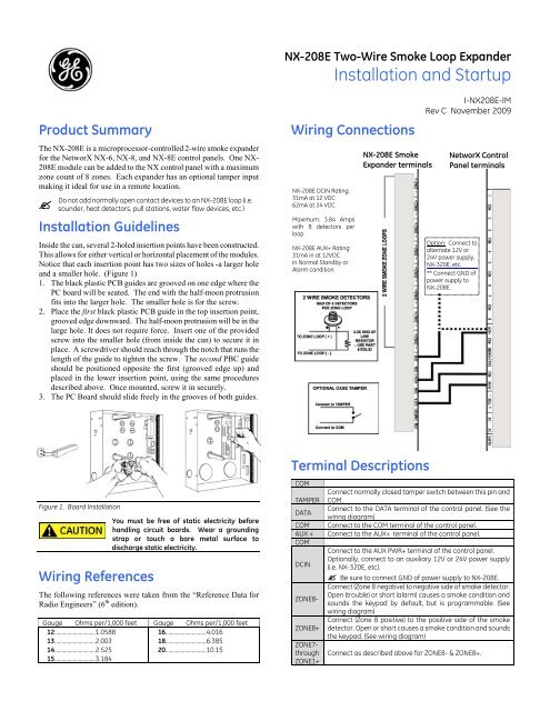
Product Summary<br />
The NX-208E is a microprocessor-controlled 2-wire smoke expander<br />
for the NetworX NX-6, NX-8, and NX-8E control panels. One NX-<br />
208E module can be added to the NX control panel with a maximum<br />
zone count of 8 zones. Each expander has an optional tamper input<br />
making it ideal for use in a remote location.<br />
<br />
Installation Guidelines<br />
Do not add normally open contact devices to an NX-208E loop (i.e.<br />
sounder, heat detectors, pull stations, water flow devices, etc.)<br />
Inside the can, several 2-holed insertion points have been constructed.<br />
This allows for either vertical or horizontal placement of the modules.<br />
Notice that each insertion point has two sizes of holes -a larger hole<br />
and a smaller hole. (Figure 1)<br />
1. The black plastic PCB guides are grooved on one edge where the<br />
PC board will be seated. The end with the half-moon protrusion<br />
fits into the larger hole. The smaller hole is for the screw.<br />
2. Place the first black plastic PCB guide in the top insertion point,<br />
grooved edge downward. The half-moon protrusion will be in the<br />
large hole. It does not require force. Insert one of the provided<br />
screw into the smaller hole (from inside the can) to secure it in<br />
place. A screwdriver should reach through the notch that runs the<br />
length of the guide to tighten the screw. The second PBC guide<br />
should be positioned opposite the first (grooved edge up) and<br />
placed in the lower insertion point, using the same procedures<br />
described above. Once mounted, screw it in securely.<br />
3. The PC Board should slide freely in the grooves of both guides.<br />
Wiring Connections<br />
NX-208E DCIN Rating:<br />
31mA at 12 VDC<br />
62mA at 24 VDC<br />
Maximum: 3.84 Amps<br />
with 8 detectors per<br />
loop<br />
NX-208E AUX+ Rating:<br />
31mA in at 12VDC<br />
in Normal Standby or<br />
Alarm condition<br />
NX-208E <strong>Smoke</strong><br />
<strong>Expander</strong> terminals<br />
I-<strong>NX208E</strong>-IM<br />
Rev C November 2009<br />
NetworX Control<br />
Panel terminals<br />
Option: Connect to<br />
alternate 12V or<br />
24V power supply,<br />
NX-320E, etc.<br />
** Connect GND of<br />
power supply to<br />
NX-208E.<br />
Figure 1. Board Installation<br />
Wiring References<br />
You must be free of static electricity before<br />
handling circuit boards. Wear a grounding<br />
strap or touch a bare metal surface to<br />
discharge static electricity.<br />
The following references were taken from the “Reference Data for<br />
Radio Engineers” (6 th edition).<br />
Gauge Ohms per/1,000 feet Gauge Ohms per/1,000 feet<br />
12.............................1.0588<br />
13.............................2.003<br />
14.............................2.525<br />
16.............................4.016<br />
18.............................6.385<br />
20.............................10.15<br />
15.............................3.184<br />
Terminal Descriptions<br />
COM<br />
TAMPER<br />
DATA<br />
COM<br />
AUX +<br />
COM<br />
DCIN<br />
ZONE8-<br />
ZONE8+<br />
ZONE7-<br />
through<br />
ZONE1+<br />
Connect normally closed tamper switch between this pin and<br />
COM.<br />
Connect to the DATA terminal of the control panel. (See the<br />
wiring diagram)<br />
Connect to the COM terminal of the control panel.<br />
Connect to the AUX+ terminal of the control panel.<br />
Connect to the AUX PWR+ terminal of the control panel.<br />
Optionally, connect to an auxiliary 12V or 24V power supply<br />
(i.e. NX-320E, etc).<br />
Be sure to connect GND of power supply to NX-208E.<br />
Connect (Zone 8 negative) to negative side of smoke detector.<br />
Open (trouble) or short (alarm) causes a smoke condition and<br />
sounds the keypad by default, but is programmable. (See<br />
wiring diagram)<br />
Connect (Zone 8 positive) to the positive side of the smoke<br />
detector. Open or short causes a smoke condition and sounds<br />
the keypad. (See wiring diagram)<br />
Connect as described above for ZONE8- & ZONE8+.
2<br />
NX-208E Two-Wire <strong>Smoke</strong> <strong>Loop</strong><br />
Installation Instructions<br />
Enrolling The Module<br />
The NetworX control panels have the ability to automatically find and<br />
store in memory the presence of all keypads, zone expanders, wireless<br />
receivers and any other module connected to the data terminal. This<br />
allows these modules to be supervised by the control panel.<br />
To enroll the modules, enter the Program Mode of the control panel<br />
(refer to the installation manual for the specific control panel). When<br />
the Program Mode is exited, it will automatically enroll the devices.<br />
The enrolling process takes about 12 seconds, during which time the<br />
“Service” LED will illuminate. User codes will not be accepted<br />
during the enrolling process. Once a module is enrolled, if it is not<br />
detected by the control panel the “Service” LED will illuminate.<br />
Module Address<br />
This 2-wire smoke module has a fixed address of 95. When<br />
programming the expander module, enter the Program Mode and<br />
select the device address as 95. (Refer to "Programming Mode"<br />
section for further details.)<br />
Programming Mode<br />
1. To enter the program mode, press []-[8]. All of the function<br />
key LEDs will begin to flash.<br />
2. Enter the "Go To Program" code (factory default is [9]-[7]-[1]-<br />
[3]). If the code was valid, the Service LED will flash, and the<br />
function LEDs will illuminate steady, indicating the device to<br />
program should be entered.<br />
3. Press [9]-[5]-[#] for the fixed address of the 2-wire smoke<br />
module. The Armed LED will illuminate while it is waiting for<br />
a programming location to be entered.<br />
4. Enter the desired programming location. The Armed LED will<br />
begin to flash while a programming location is being entered.<br />
5. Press [#]. If this is a valid location, the Armed LED will<br />
extinguish, the Ready LED will illuminate, and the binary data<br />
for the first segment of this location will be shown on the zone<br />
LEDS.<br />
6. To change the data, enter the data followed by []. The data<br />
will be entered, and the location will automatically increment to<br />
the next segment. The data for that segment will be displayed.<br />
This procedure is repeated until the last segment is reached.<br />
Pressing the [#] key will exit from this location. To review the<br />
data, repeat the above procedure, pressing the [] key without<br />
entering data first. Each time the [] key is pressed the next<br />
segment is displayed.<br />
Programming data is always one of two types of data. The first type is<br />
numerical, and can take on values from 0-255 or 0-15 depending on<br />
the segment size. The second type is a feature selection type. Feature<br />
selection data is used to turn features on or off.<br />
LCD Keypad Users: All steps required for programming are the<br />
same as the aforementioned LED keypad. The LCD keypad display<br />
will prompt you for the data required. While in the programming<br />
mode, and not in a location, the number in parenthesis is the location<br />
you were previously changing. For example, if the display reads<br />
"Enter location, then # (5)", it is reminding you that location 5 was<br />
the last location you programmed. In feature selection data, the<br />
numbers of the enabled features will be displayed. However, the<br />
features not enabled will display a hyphen (-).<br />
Programming Location Guide<br />
The programming for all zone information is performed in the<br />
NetworX control panels. For instructions on accessing and<br />
programming the control panel as well as changing the characteristics<br />
of a configuration group, refer to the installation manual for the<br />
corresponding control panel.<br />
LOCATION 0 - ENABLING THE ZONES (LOOPS)<br />
(1 segment, feature selection data) Location 0 is used to enable /<br />
disable the zone(s). Factory default = all zones disabled.<br />
1 = Zone 1<br />
2 = Zone 2<br />
3 = Zone 3<br />
4 = Zone 4<br />
5 = Zone 5<br />
6 = Zone 6<br />
LOCATION 1 - SETTING THE ZONE BANK DURING<br />
COMMUNICATION<br />
7 = Zone 7<br />
8 = Zone 8<br />
(1 segment, numerical data) Location 1 is used to select the bank<br />
used by zones 1-192 during communication. A zone may reside in<br />
any one of the 24 banks.<br />
<br />
If you enter [1] through [23], then zones 1-8 in location 0 become<br />
the corresponding zones as shown in the following chart.<br />
Example: Entering [9] in Location 1 causes zone 1 to become zone<br />
73, and zone 8 becomes 80. Factory default = 1 (Zones 9-16)<br />
0 = Zones 1 - 8 8 = Zones 65 - 72 16 = Zones 129 – 136<br />
1 = Zones 9 - 16 9 = Zones 73 – 80 17 = Zones 137 - 144<br />
2 = Zones 17 - 24 10 = Zones 81 – 88 18 = Zones 145 – 152<br />
3 = Zones 25 - 32 11 = Zones 89 - 96 19 = Zones 153 – 160<br />
4 = Zones 33 - 40 12 = Zones 97 - 104 20 = Zones 161 - 168<br />
5 = Zones 41 - 48 13 = Zones 105 - 112 21 = Zones 169 - 176<br />
6 = Zones 49 - 56 14 = Zones 113 - 120 22 = Zones 177 - 184<br />
7 = Zones 57 - 64 15 = Zones 121 - 128 23 = Zones 185 - 192<br />
LOCATION 2<br />
SPECIAL FLAGS<br />
(1 segment, feature selection data) Location 2 is used to select<br />
special flags for communication. Factory default = all flags disabled.<br />
<br />
Seg 1 - 24V Configuration requires a total of four 12V, 17AH<br />
batteries – Connect 2 batteries in parallel, and connect the other 2<br />
batteries in parallel. Then connect those two sets in series.<br />
1 = enables the 24 V power supply option (see Note)<br />
2 = disables the temporal<br />
3 = enables temporal regardless of panel programming<br />
4 = enables tamper<br />
5 = disables voltage reversal (not perform voltage reversal functions<br />
when in alarm; used in con-junction with smokes that have<br />
sounders)<br />
Compatible <strong>Smoke</strong> Detector List<br />
• S09A Compatible Devices<br />
429AT, 521B/BXT (SW1 ON), 521NB/NBXT<br />
• S10A Compatible Devices<br />
521NB,521NBXT,521NCSXT, 429C, 429CT, 521B/BXT<br />
(SW1 OFF), 711U/UT, 721U/UT<br />
• S11A Compatible Devices<br />
429CRT,429CST, 521CRXT, 521NCRXT, 521NCSRXT,<br />
731U
NX-208E Two-Wire <strong>Smoke</strong> <strong>Loop</strong><br />
Installation Instructions<br />
3<br />
Programming Worksheet<br />
Loc Description Default Your Data<br />
0 ZONE ENABLE (1 segment) 0 (disabled) _ _ _ _ _ _ _ _<br />
1 = Zone 1<br />
2 = Zone 2<br />
3 = Zone 3<br />
4 = Zone 4<br />
5 = Zone 5<br />
6 = Zone 6<br />
7 = Zone 7<br />
8 = Zone 8<br />
1 BANK SELECTION (1 segment) 1 __<br />
0 = Zones 1 - 8 12 = Zones 97 - 104<br />
1 = Zones 9 - 16 13 = Zones 105 - 112<br />
2 = Zones 17 - 24 14 = Zones 113 - 120<br />
3 = Zones 25 - 32 15 = Zones 121 - 128<br />
4 = Zones 33 - 40 16 = Zones 129 – 136<br />
5 = Zones 41 - 48 17 = Zones 137 - 144<br />
6 = Zones 49 - 56 18 = Zones 145 – 152<br />
7 = Zones 57 - 64 19 = Zones 153 – 160<br />
8 = Zones 65 - 72 20 = Zones 161 - 168<br />
9 = Zones 73 – 80 21 = Zones 169 - 176<br />
10 = Zones 81 – 88 22 = Zones 177 - 184<br />
11 = Zones 89 - 96 23 = Zones 185 - 192<br />
2 SPECIAL FLAGS (1 segment) 0 (disabled)<br />
1 = 24 Volt Power Supply <br />
2 = Disable temporal<br />
3 = Temporal regardless<br />
4 = Enable tamper<br />
5 = Disable voltage reversal<br />
Loc 2, Seg 1 - 24V Configuration requires a total of four 12V, 17AH batteries –<br />
Connect 2 batteries in parallel, and connect the other 2 batteries in parallel. Then<br />
connect those two sets in series.<br />
Underwriters Laboratories<br />
UL609 Local Grade A Mercantile, Police Station Connect with Basic<br />
Line <strong>Security</strong> (* requires #NX-003-C enclosure)<br />
UL985 Household Fire Warning Systems & Units<br />
UL1023 Household Burglary Alarm Systems & Units<br />
UL1610 Central Station Burglar Alarm Unit<br />
Canada / ULC<br />
S303 Local Burglar Alarm Units and Systems<br />
S545 Standard for Residential Fire Warning System Control Units<br />
Specifications<br />
OPERATING POWER<br />
AUXILIARY POWER<br />
CURRENT DRAW<br />
DCIN CURRENT DRAW<br />
AUX+ RATING<br />
LOOP RESISTANCE<br />
LOOP RESPONSE<br />
OPERATING TEMPERATURE<br />
DIMENSIONS<br />
SHIPPING WEIGHT<br />
Ordering Information<br />
PART #<br />
NX-208E<br />
EOL33<br />
12VDC Supplied from NetworX models:<br />
NX-6, NX-8, NX-8E, or NX-320E<br />
IMPORTANT: Supplied power from external<br />
supplies must be UL listed for Fire or<br />
Burglary.<br />
Supplied from NetworX models:<br />
NX-6, NX-8, NX-8E, or NX-320E; Current<br />
limited to 100mA<br />
30mA<br />
31mA maximum @ 12VDC<br />
62mA maximum @ 24VDC<br />
3.84 Amps MAX (with 8 detectors per loop)<br />
13mA @ 12VDC in Normal Standby<br />
53mA @ 12VDC in Alarm<br />
12 Volt <strong>Loop</strong> = 20 Ohms Maximum<br />
24 Volt <strong>Loop</strong> = 50 Ohms Maximum<br />
180mS<br />
32 to 120 degrees F<br />
9.5" Wide<br />
3.5" High<br />
1.0" Deep<br />
2 lbs.<br />
DESCRIPTION<br />
Two Wire <strong>Smoke</strong> <strong>Loop</strong> <strong>Expander</strong><br />
3.3K End-of-Line Resistor device<br />
Other available NetworX modules:<br />
NX-216E 16 Zone <strong>Expander</strong> Module<br />
NX-320E Smart Power Supply and Buss Extender<br />
NX-507E Seven Relay Module<br />
Toll-free: 888.437.3287<br />
Outside the toll-free area:<br />
Technical Support<br />
(U.S. including Alaska, Hawaii, Puerto Rico, and Canada<br />
Contact your local dealer<br />
www.gesecurity.com